Embed Size (px)
Citation preview
CampusDesign Summary
August 2014 Series
Table of Contents
Table of ContentsPreface ........................................................................................................................................1
Introduction .................................................................................................................................2
Campus Wired LAN Design Summary ..........................................................................................3Hierarchical Design Model .......................................................................................................... 3Access Layer .............................................................................................................................. 5
Access-Layer Platforms ......................................................................................................... 5Distribution Layer ........................................................................................................................ 6
Two-Tier Design ..................................................................................................................... 6Three-Tier Design................................................................................................................... 8Distribution-Layer Platforms ................................................................................................... 9
Core Layer .................................................................................................................................. 9Core Layer Platforms ............................................................................................................ 10
Quality of Service (QoS) ........................................................................................................... 10
Additional Wired LAN Designs ...................................................................................................12Device Management Using Cisco Secure ACS ..........................................................................12Cisco Network Analysis Module .................................................................................................12
Services Block Distribution Switch Design .............................................................................13Service Block Appliance Design ............................................................................................13Data Center Appliance Design ...............................................................................................13Remote Site Design ...............................................................................................................14Real-Time and Historical Application Monitoring ....................................................................14Application and Service Delivery with Application Performance Intelligence ..........................14Simplified Problem Detection and Resolution ........................................................................14Cisco Prime NAM Data Sources and Export Capabilities .......................................................14
Cisco Prime Infrastructure ......................................................................................................... 15Device Work Center ............................................................................................................. 16Configuration Templates and Tasks ...................................................................................... 16Alarms, Events, and Syslog Messages ................................................................................. 16Reporting.............................................................................................................................. 16CleanAir Support ...................................................................................................................17Network Analysis Module Support.........................................................................................17
Table of Contents
Campus Wireless LAN Design Summary ....................................................................................18Cisco Wireless LAN Controllers ................................................................................................ 20Cisco Lightweight Access Points .............................................................................................. 21Wireless Design Models ........................................................................................................... 22
Local-Mode Design Model .................................................................................................. 22Cisco FlexConnect Design Model ......................................................................................... 23
High Availability ......................................................................................................................... 25Multicast Support ...................................................................................................................... 25Band Select .............................................................................................................................. 26ClientLink .................................................................................................................................. 27802.11ac Bandwidth Performance ............................................................................................. 29802.11ac Channel Planning ....................................................................................................... 29Guest Wireless ......................................................................................................................... 31
Additional Wireless LAN Designs ...............................................................................................33Campus Wireless CleanAir ....................................................................................................... 33
Cisco CleanAir Technology ................................................................................................... 33Cisco Prime Infrastructure with Cisco CleanAir Technology .................................................. 33
Cisco OfficeExtend ................................................................................................................... 34Cisco Wireless LAN Controllers ........................................................................................... 34Cisco OfficeExtend Access Points ....................................................................................... 35Design Models ..................................................................................................................... 35
Preface August 2014 Series1
PrefaceCisco Validated Designs (CVDs) present systems that are based on common use cases or engineering priorities. CVDs incorporate a broad set of technologies, features, and applications that address customer needs. They incorporate a broad set of technologies, features, and applications to address customer needs. Cisco engineers have comprehensively tested and documented each CVD in order to ensure faster, more reliable, and fully predictable deployment.
This design summary provides information about the use cases covered in a series or set of related CVD guides and summarizes the Cisco products and technologies that solve the challenges presented by the use cases.
CVD Foundation SeriesThis CVD Foundation guide is a part of the August 2014 Series. As Cisco develops a CVD Foundation series, the guides themselves are tested together, in the same network lab. This approach assures that the guides in a series are fully compatible with one another. Each series describes a lab-validated, complete system.
The CVD Foundation series incorporates wired and wireless LAN, WAN, data center, security, and network management technologies. Using the CVD Foundation simplifies system integration, allowing you to select solutions that solve an organization’s problems—without worrying about the technical complexity.
To ensure the compatibility of designs in the CVD Foundation, you should use guides that belong to the same release. For the most recent CVD Foundation guides, please visit the CVD Foundation web site.
Comments and QuestionsIf you would like to comment on a guide or ask questions, please use the feedback form.
Introduction August 2014 Series2
IntroductionThere is a tendency to discount the network as just simple plumbing, to think that all you have to consider is the size and the length of the pipes or the speeds and feeds of the links, and to dismiss the rest as unimportant. Just as the plumbing in a large stadium or high rise has to be designed for scale, purpose, redundancy, protection from tampering or denial of operation, and the capacity to handle peak loads, the network requires similar consideration. As users depend on the network to access the majority of the information they need to do their jobs and to transport their voice or video with reliability, the network must be able to provide resilient, intelligent transport.
Even with the large amount of bandwidth available to LAN backbones, there are performance-sensitive applications affected by jitter, delay, and packet loss. It is the function of the network foundation to provide an efficient, fault-tolerant transport that can differentiate application traffic to make intelligent load-sharing decisions when the network is temporarily congested. Whether a user’s network access is wired or wireless, at the headquarters or at a remote site, the network must provide intelligent prioritization and queuing of traffic along the most efficient route possible.
Cisco Validated Designs for Campus incorporate both wired and wireless connectivity for a complete network access solution. This document explains:
• The design of the campus wired LAN foundation.
• How the wireless LAN extends secure network access for your mobile workforce.
• How the wireless LAN can provide guest access for contractors and visitors to your facilities.
All CVD guides referenced in this design summary are available at:
www.cisco.com/go/cvd/campus
Campus Wired LAN Design Summary August 2014 Series3
Campus Wired LAN Design Summary
The LAN is the networking infrastructure that provides access to network communication services and resources for end users and devices spread over a single floor or building. A campus network is created by interconnecting a group of LANs that are spread over a small geographic area. Campus network design concepts are inclusive small networks that use a single LAN switch up to very large networks with thousands of connections.
The Campus Wired LAN Technology Design Guide enables communications between devices in a building or group of buildings, as well as interconnection to the WAN and Internet edge modules at the network core.
Specifically, this design provides a network foundation and services that enable:
• Tiered LAN connectivity
• Wired network access for employees
• IP Multicast for efficient data distribution
• Wired infrastructure ready for multimedia services
Hierarchical Design ModelThe Campus Wired LAN Technology Design Guide uses a hierarchical design model to break the design up into modular groups or layers. Breaking the design up into layers allows each layer to implement specific functions, which simplifies the network design and therefore the deployment and management of the network.
Modularity in network design allows you to create design elements that can be replicated throughout the network. Replication provides an easy way to scale the network as well as a consistent deployment method.
In flat or meshed network architectures, changes tend to affect a large number of systems. Hierarchical design helps constrain operational changes to a subset of the network, which makes it easy to manage as well as improve resiliency. Modular structuring of the network into small, easy-to-understand elements also facilitates resiliency via improved fault isolation.
A hierarchical LAN design includes the following three layers:
• Access layer—Provides endpoints and users direct access to the network
• Distribution layer—Aggregates access layers and provides connectivity to services
• Core layer—Provides connectivity between distribution layers for large LAN environments
Campus Wired LAN Design Summary August 2014 Series4
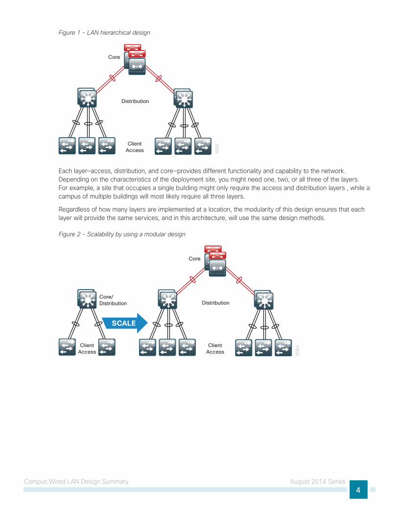
Figure 1 - LAN hierarchical design
10
02Client
Access
Distribution
Core
Each layer—access, distribution, and core—provides different functionality and capability to the network. Depending on the characteristics of the deployment site, you might need one, two, or all three of the layers. For example, a site that occupies a single building might only require the access and distribution layers , while a campus of multiple buildings will most likely require all three layers.
Regardless of how many layers are implemented at a location, the modularity of this design ensures that each layer will provide the same services, and in this architecture, will use the same design methods.
Figure 2 - Scalability by using a modular design
20
84Client
Access
Distribution
Core
Core/Distribution
SCALE
ClientAccess
Campus Wired LAN Design Summary August 2014 Series5
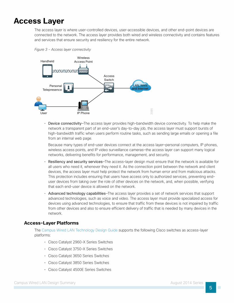
Access LayerThe access layer is where user-controlled devices, user-accessible devices, and other end-point devices are connected to the network. The access layer provides both wired and wireless connectivity and contains features and services that ensure security and resiliency for the entire network.
Figure 3 - Access layer connectivity
20
85
AccessSwitch
WirelessAccess Point
PersonalTelepresence
Handheld
IP PhoneUser
LAN, WANand Internet
• Device connectivity—The access layer provides high-bandwidth device connectivity. To help make the network a transparent part of an end-user’s day-to-day job, the access layer must support bursts of high-bandwidth traffic when users perform routine tasks, such as sending large emails or opening a file from an internal web page.
Because many types of end-user devices connect at the access layer—personal computers, IP phones, wireless access points, and IP video surveillance cameras—the access layer can support many logical networks, delivering benefits for performance, management, and security.
• Resiliency and security services—The access-layer design must ensure that the network is available for all users who need it, whenever they need it. As the connection point between the network and client devices, the access layer must help protect the network from human error and from malicious attacks. This protection includes ensuring that users have access only to authorized services, preventing end-user devices from taking over the role of other devices on the network, and, when possible, verifying that each end-user device is allowed on the network.
• Advanced technology capabilities—The access layer provides a set of network services that support advanced technologies, such as voice and video. The access layer must provide specialized access for devices using advanced technologies, to ensure that traffic from these devices is not impaired by traffic from other devices and also to ensure efficient delivery of traffic that is needed by many devices in the network.
Access-Layer PlatformsThe Campus Wired LAN Technology Design Guide supports the following Cisco switches as access-layer platforms:
• Cisco Catalyst 2960-X Series Switches
• Cisco Catalyst 3750-X Series Switches
• Cisco Catalyst 3650 Series Switches
• Cisco Catalyst 3850 Series Switches
• Cisco Catalyst 4500E Series Switches
Campus Wired LAN Design Summary August 2014 Series6
Distribution LayerThe distribution layer supports many important services. In a network where connectivity needs to traverse the LAN end-to-end, whether between different access layer devices or from an access layer device to the WAN, the distribution layer facilitates this connectivity.
• Scalability—At any site with more than two or three access-layer devices, it is impractical to interconnect all access switches. The distribution layer serves as an aggregation point for multiple access-layer switches.
The distribution layer can lower operating costs by making the network more efficient, by requiring less memory, by creating fault domains that compartmentalize failures or network changes, and by processing resources for devices elsewhere in the network. The distribution layer also increases network availability by containing failures to smaller domains.
• Reduce complexity and increase resiliency—Campus Wired LAN Technology Design Guide uses a simplified distribution layer, in which a distribution-layer node consists of a single logical entity that can be implemented using a pair of physically separate switches operating as one device or using a physical stack of switches operating as one device. Resiliency is provided by physically redundant components like power supplies, supervisors, and modules, as well as Stateful Switchover to redundant logical control planes.
This approach reduces complexity of configuring and operating the distribution layer because fewer protocols are required. Little or no tuning is needed to provide near-second or sub-second convergence around failures or disruptions.
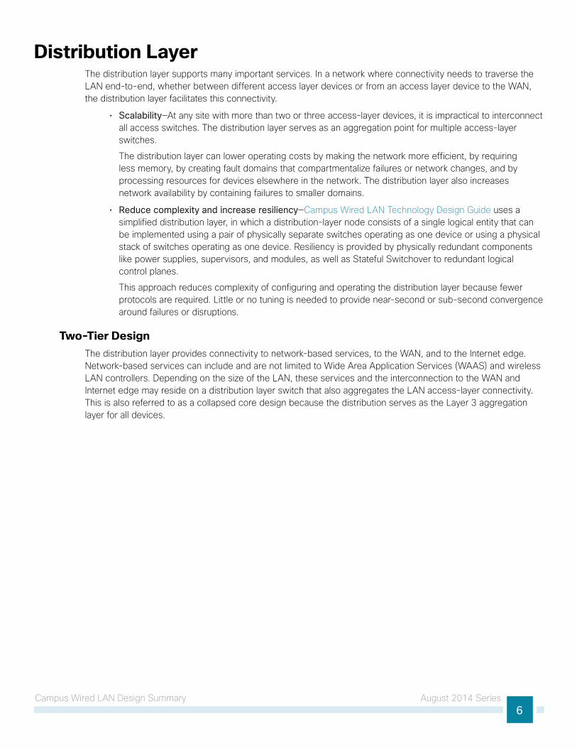
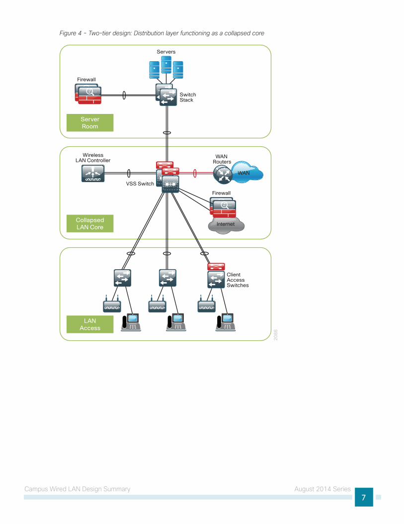
Two-Tier DesignThe distribution layer provides connectivity to network-based services, to the WAN, and to the Internet edge. Network-based services can include and are not limited to Wide Area Application Services (WAAS) and wireless LAN controllers. Depending on the size of the LAN, these services and the interconnection to the WAN and Internet edge may reside on a distribution layer switch that also aggregates the LAN access-layer connectivity. This is also referred to as a collapsed core design because the distribution serves as the Layer 3 aggregation layer for all devices.
Campus Wired LAN Design Summary August 2014 Series7
Figure 4 - Two-tier design: Distribution layer functioning as a collapsed core
20
86
LANAccess
CollapsedLAN Core
ServerRoom
ClientAccessSwitches
VSS Switch
SwitchStack
WirelessLAN Controller
Servers
Firewall
WAN
WAN Routers
Internet
Firewall
Campus Wired LAN Design Summary August 2014 Series8
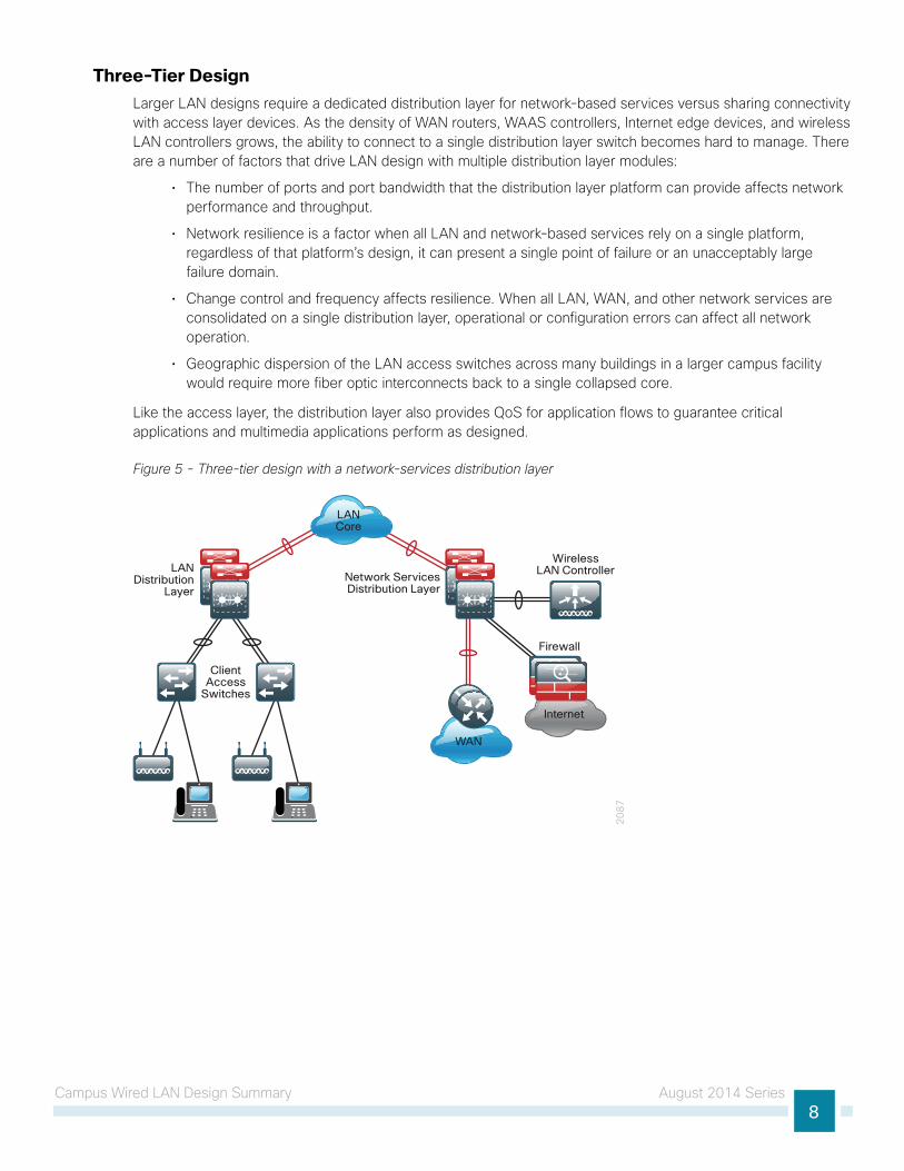
Three-Tier DesignLarger LAN designs require a dedicated distribution layer for network-based services versus sharing connectivity with access layer devices. As the density of WAN routers, WAAS controllers, Internet edge devices, and wireless LAN controllers grows, the ability to connect to a single distribution layer switch becomes hard to manage. There are a number of factors that drive LAN design with multiple distribution layer modules:
• The number of ports and port bandwidth that the distribution layer platform can provide affects network performance and throughput.
• Network resilience is a factor when all LAN and network-based services rely on a single platform, regardless of that platform’s design, it can present a single point of failure or an unacceptably large failure domain.
• Change control and frequency affects resilience. When all LAN, WAN, and other network services are consolidated on a single distribution layer, operational or configuration errors can affect all network operation.
• Geographic dispersion of the LAN access switches across many buildings in a larger campus facility would require more fiber optic interconnects back to a single collapsed core.
Like the access layer, the distribution layer also provides QoS for application flows to guarantee critical applications and multimedia applications perform as designed.
Figure 5 - Three-tier design with a network-services distribution layer
WAN
20
87
LANDistribution
Layer
ClientAccess
Switches
LANCore
Internet
Network ServicesDistribution Layer
WirelessLAN Controller
Firewall
Campus Wired LAN Design Summary August 2014 Series9
Distribution-Layer PlatformsThe Campus Wired LAN Technology Design Guide supports the following Cisco switches as distribution-layer platforms:
• Cisco Catalyst 6807-XL Series Switches with Supervisor Engine 2T
• Cisco Catalyst 6500 Series Switches with Supervisor Engine 2T
• Cisco Catalyst 6880-X Series Switches
• Cisco Catalyst 4500-X Series Switches
• Cisco Catalyst 4500E Series Switches
• Cisco Catalyst 3850 Series Switches
• Cisco Catalyst 3750-X Series Switches
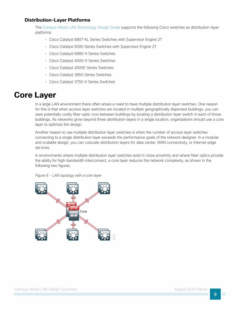
Core LayerIn a large LAN environment there often arises a need to have multiple distribution layer switches. One reason for this is that when access layer switches are located in multiple geographically dispersed buildings, you can save potentially costly fiber-optic runs between buildings by locating a distribution layer switch in each of those buildings. As networks grow beyond three distribution layers in a single location, organizations should use a core layer to optimize the design.
Another reason to use multiple distribution layer switches is when the number of access layer switches connecting to a single distribution layer exceeds the performance goals of the network designer. In a modular and scalable design, you can colocate distribution layers for data center, WAN connectivity, or Internet edge services.
In environments where multiple distribution layer switches exist in close proximity and where fiber optics provide the ability for high-bandwidth interconnect, a core layer reduces the network complexity, as shown in the following two figures.
Figure 6 - LAN topology with a core layer
20
88
Core
Campus Wired LAN Design Summary August 2014 Series10
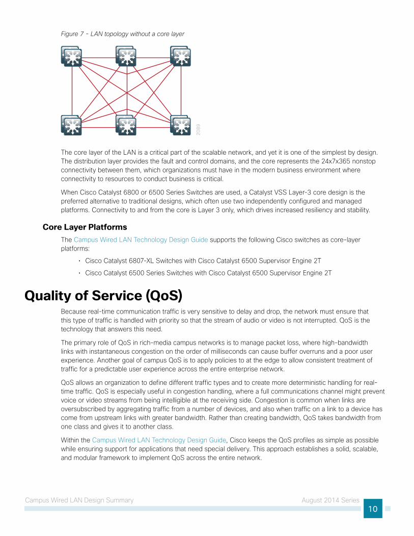
Figure 7 - LAN topology without a core layer
20
89
The core layer of the LAN is a critical part of the scalable network, and yet it is one of the simplest by design. The distribution layer provides the fault and control domains, and the core represents the 24x7x365 nonstop connectivity between them, which organizations must have in the modern business environment where connectivity to resources to conduct business is critical.
When Cisco Catalyst 6800 or 6500 Series Switches are used, a Catalyst VSS Layer-3 core design is the preferred alternative to traditional designs, which often use two independently configured and managed platforms. Connectivity to and from the core is Layer 3 only, which drives increased resiliency and stability.
Core Layer PlatformsThe Campus Wired LAN Technology Design Guide supports the following Cisco switches as core-layer platforms:
• Cisco Catalyst 6807-XL Switches with Cisco Catalyst 6500 Supervisor Engine 2T
• Cisco Catalyst 6500 Series Switches with Cisco Catalyst 6500 Supervisor Engine 2T
Quality of Service (QoS)Because real-time communication traffic is very sensitive to delay and drop, the network must ensure that this type of traffic is handled with priority so that the stream of audio or video is not interrupted. QoS is the technology that answers this need.
The primary role of QoS in rich-media campus networks is to manage packet loss, where high-bandwidth links with instantaneous congestion on the order of milliseconds can cause buffer overruns and a poor user experience. Another goal of campus QoS is to apply policies to at the edge to allow consistent treatment of traffic for a predictable user experience across the entire enterprise network.
QoS allows an organization to define different traffic types and to create more deterministic handling for real-time traffic. QoS is especially useful in congestion handling, where a full communications channel might prevent voice or video streams from being intelligible at the receiving side. Congestion is common when links are oversubscribed by aggregating traffic from a number of devices, and also when traffic on a link to a device has come from upstream links with greater bandwidth. Rather than creating bandwidth, QoS takes bandwidth from one class and gives it to another class.
Within the Campus Wired LAN Technology Design Guide, Cisco keeps the QoS profiles as simple as possible while ensuring support for applications that need special delivery. This approach establishes a solid, scalable, and modular framework to implement QoS across the entire network.

Campus Wired LAN Design Summary August 2014 Series11
The primary goals of implementing QoS within the network are:
• Expedited delivery service of communications for supported, real-time applications.
• Business continuance for business-critical applications.
• Fairness among all other applications when congestion occurs.
• Deprioritized background applications and non-business entertainment-oriented applications so that these do not delay interactive or business-critical applications.
• A trusted edge around the network to guarantee that users cannot inject their own arbitrary priority values and to allow the organization to trust marked traffic throughout the network.
To accomplish these goals, the design implements QoS across the network as follows:
• Establish a limited number of traffic classes (that is, one to eight classes) within the network that need special handling (for example, real-time voice, real-time video, high-priority data, interactive traffic, batch traffic, and default classes).
• Classify applications into the traffic classes.
• Apply special handling to the traffic classes to achieve intended network behavior.
Additional Wired LAN Designs August 2014 Series12
Additional Wired LAN DesignsValidated in the Campus Wired LAN Technology Design Guide environment, several other CVD guides are available, with a focus on the management and monitoring of a campus network.
Device Management Using Cisco Secure ACSWithout a centralized access and identity policy enforcement point, it’s difficult to ensure the reliability of a network as the number of network devices and administrators increases.
Cisco Secure Access Control System (ACS) operates as a centralized authentication, authorization, and accounting (AAA — pronounced “triple A”) server that combines user authentication, user and administrator access control, and policy control in a single solution. Cisco Secure ACS uses a rule-based policy model, which allows for security policies that grant access privileges based on many different attributes and conditions in addition to a user’s identity.
The capabilities of Cisco Secure ACS coupled with an AAA configuration on the network devices reduce the administrative issues that surround having static local account information on each device. Cisco Secure ACS can provide centralized control of authentication, which allows the organization to quickly grant or revoke access for a user on any network device.
Rule-based mapping of users to identity groups can be based on information available in an external directory or an identity store such as Microsoft Active Directory. Network devices can be categorized in multiple device groups, which can function as a hierarchy based on attributes such as location, manufacturer, or role in the network. The combination of identity and device groups allows you to easily create authorization rules that define which network administrators can authenticate against which devices.
These same authorization rules allow for privilege-level authorization, which can be used to give limited access to the commands on a device. For example, a rule can give network administrators full access to all commands or limit helpdesk users to monitoring commands.
The Device Management Using Cisco Secure ACS Technology Design Guide is available at www.cisco.com/go/cvd/campus
Cisco Network Analysis ModuleBusinesses rely on enterprise applications to help ensure efficient operations and gain competitive advantage. At the same time, IT is challenged with managing application delivery in an environment that is dynamic and distributed. Because of new business demands, comprehensive application and network-visibility is business critical for achieving increased operational efficiency and successful management of the overall end-user experience.
You can use Cisco Prime Network Analysis Module (NAM) to maintain and improve operational efficiency. Cisco Prime NAM includes essential features that allow you to analyze and troubleshoot application performance and voice, capture packets continuously, and see pre- and post- WAN optimization.
Additional Wired LAN Designs August 2014 Series13
Cisco Prime NAM, part of the overall Cisco Prime solution, is a product that:
• Provides advanced network instrumentation on the user-services layer in order to support data, voice, and video services.
• Allows network administrators, managers, and engineers to gain visibility into the user-services layer with a simple workflow approach—from monitoring overall network health to analyzing a variety of detailed metrics and troubleshooting with packet-level details.
• Supports network-services layers such as application optimization.
• Offers a versatile combination of real-time traffic analysis, historical analysis, packet capture capabilities, and the ability to measure user-perceived delays across the WAN.
• Provides a uniform instrumentation layer that collects data from a variety of sources, and then analyzes and presents the information. This information is available through an onboard web-based graphical user interface, and you can also export it to third-party applications.
The Network Analysis Module Technology Design Guide provides several design options for deployment of Cisco NAM in your campus network.
Services Block Distribution Switch DesignThe Cisco Catalyst 6500 Series Network Analysis Module (NAM-3) is deployed in the Cisco Catalyst 6500 Series switch found in services block distribution in the campus. NAM-3 takes advantage of backplane integration by simplifying manageability, lowering total cost of ownership, reducing network footprint, and reducing rack space. Cisco NAM-3 monitors traffic on the Cisco Catalyst 6807-XL or 6500 switches via two internal 10-Gigabit data ports.
The services block distribution switch design uses Cisco NAM-3 for the following:
• Voice and video quality at the campus
• Traffic utilization and application performance between campus to data center and campus to remote site
• Packet capture for troubleshooting
• URL monitoring for web filtering policies, quality of service (QoS) for enforcement of QoS policies
• Application and host analysis, such as all traffic on an interface or in a VLAN
Service Block Appliance DesignIn this design, the Cisco Prime NAM 2320 appliance is deployed in the services block distribution connected to Cisco Catalyst 6807-XL or 6500 series switches. Cisco Prime NAM 2320 has the flexibility to connect to any platform (including Catalyst and Nexus series platforms) that supports SPAN/RSPAN/ERSPAN for local switch visibility. The Cisco Prime NAM 2320 appliance monitors traffic on the switches via two 10-Gigabit data port interfaces.
Data Center Appliance DesignThe data center appliance design uses Cisco Prime NAM 2320 for the following:
• Traffic utilization and application performance between data center to campus and data center to remote site
• WAN optimization analysis and troubleshooting
• Packet capture for troubleshooting
• QoS for enforcement of QoS policies
• Application and host analysis, such as all traffic on an interface or in a VLAN
Additional Wired LAN Designs August 2014 Series14
Remote Site DesignCisco Prime NAM on Cisco Services Ready Engine (SRE) 710 or 910 series as part of ISR G2 is deployed in the remote site, which helps you monitor, measure, and report on the network’s health at the remote-site level.
The remote site design uses Cisco Prime NAM SRE for the following:
• Voice and video quality at the remote site
• Traffic utilization and application performance between remote site to data center, remote site to campus, and remote site to remote site
• Packet capture for troubleshooting
• URL monitoring for web filtering policies, QoS for enforcement of QoS policies
• Application and host analysis, such as all traffic on an interface or in a VLAN
Real-Time and Historical Application MonitoringCisco Prime NAM monitors traffic in real-time and provides a variety of analytics. It delivers on-demand historical analysis from the data collected. This category of monitoring includes application recognition, analysis of top conversations, hosts, protocols, differentiated services code points, and VLANs.
Application and Service Delivery with Application Performance IntelligenceIn order to accurately assess the end-user experience, Cisco Prime NAM delivers comprehensive application performance intelligence (API) measurements. It analyzes TCP-based client/server requests and acknowledgements in order to provide transaction-aware response-time statistics, such as client delay, server delay, network delay, transaction times, and connection status. This data can help you isolate application problems to the network or to the server. It can also help you quickly diagnose the root cause of the delay and thus resolve the problem while minimizing end-user impact.
API can assist busy IT staff in troubleshooting application performance problems, analyzing and trending application behavior, identifying application consolidation opportunities, defining and helping ensure service levels, and performing pre- and post-deployment monitoring of application optimization and acceleration services.
Simplified Problem Detection and ResolutionWith Cisco Prime NAM, you can set thresholds and alarms on various network parameters—such as increased utilization, severe application response delays, and voice quality degradation—and be alerted to potential problems. When one or more alarms are triggered, Cisco Prime NAM can send an email alert, generate a syslog or SNMP trap, and automatically capture and decode the relevant traffic to help resolve the problem. Using a browser, the administrator can manually perform captures and view decodes through the Traffic Analyzer GUI while the data is still being captured. The capture and decode capability of the Cisco Prime NAM provides depth and insight into data analysis by using trigger-based captures, filters, decodes, a capture analysis, and error-scan toolset in order to quickly pinpoint and resolve problem areas.
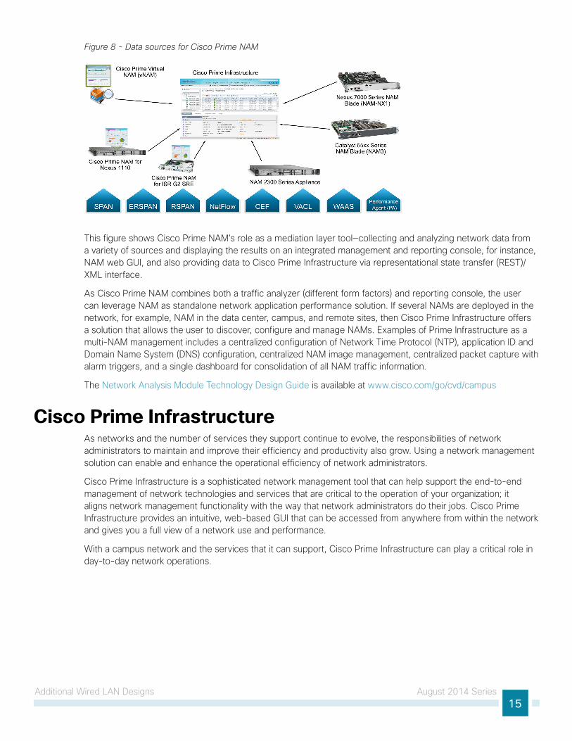
Cisco Prime NAM Data Sources and Export CapabilitiesIn the context of Cisco Prime NAM, a data source refers to a source of traffic for which the entire stream, or summaries of data from that stream, is sent to Cisco Prime NAM for monitoring. Cisco Prime NAM can monitor a variety of data sources and compute appropriate metrics. The following figure provides a snapshot of all possible sources of data, and also the various export mechanisms supported by Cisco Prime NAM.
Additional Wired LAN Designs August 2014 Series15
Figure 8 - Data sources for Cisco Prime NAM
This figure shows Cisco Prime NAM’s role as a mediation layer tool—collecting and analyzing network data from a variety of sources and displaying the results on an integrated management and reporting console, for instance, NAM web GUI, and also providing data to Cisco Prime Infrastructure via representational state transfer (REST)/XML interface.
As Cisco Prime NAM combines both a traffic analyzer (different form factors) and reporting console, the user can leverage NAM as standalone network application performance solution. If several NAMs are deployed in the network, for example, NAM in the data center, campus, and remote sites, then Cisco Prime Infrastructure offers a solution that allows the user to discover, configure and manage NAMs. Examples of Prime Infrastructure as a multi-NAM management includes a centralized configuration of Network Time Protocol (NTP), application ID and Domain Name System (DNS) configuration, centralized NAM image management, centralized packet capture with alarm triggers, and a single dashboard for consolidation of all NAM traffic information.
The Network Analysis Module Technology Design Guide is available at www.cisco.com/go/cvd/campus
Cisco Prime InfrastructureAs networks and the number of services they support continue to evolve, the responsibilities of network administrators to maintain and improve their efficiency and productivity also grow. Using a network management solution can enable and enhance the operational efficiency of network administrators.
Cisco Prime Infrastructure is a sophisticated network management tool that can help support the end-to-end management of network technologies and services that are critical to the operation of your organization; it aligns network management functionality with the way that network administrators do their jobs. Cisco Prime Infrastructure provides an intuitive, web-based GUI that can be accessed from anywhere from within the network and gives you a full view of a network use and performance.
With a campus network and the services that it can support, Cisco Prime Infrastructure can play a critical role in day-to-day network operations.
Additional Wired LAN Designs August 2014 Series16
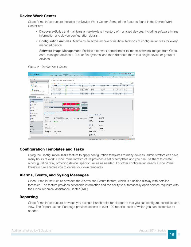
Device Work CenterCisco Prime Infrastructure includes the Device Work Center. Some of the features found in the Device Work Center are:
• Discovery—Builds and maintains an up-to-date inventory of managed devices, including software image information and device configuration details.
• Configuration Archives—Maintains an active archive of multiple iterations of configuration files for every managed device.
• Software Image Management—Enables a network administrator to import software images from Cisco.com, managed devices, URLs, or file systems, and then distribute them to a single device or group of devices.
Figure 9 - Device Work Center
Configuration Templates and TasksUsing the Configuration Tasks feature to apply configuration templates to many devices, administrators can save many hours of work. Cisco Prime Infrastructure provides a set of templates and you can use them to create a configuration task, providing device-specific values as needed. For other configuration needs, Cisco Prime Infrastructure enables you to define your own templates.
Alarms, Events, and Syslog MessagesCisco Prime Infrastructure provides the Alarms and Events feature, which is a unified display with detailed forensics. The feature provides actionable information and the ability to automatically open service requests with the Cisco Technical Assistance Center (TAC).
ReportingCisco Prime Infrastructure provides you a single launch point for all reports that you can configure, schedule, and view. The Report Launch Pad page provides access to over 100 reports, each of which you can customize as needed.

Additional Wired LAN Designs August 2014 Series17
CleanAir SupportCisco Prime Infrastructure supports the management of CleanAir enabled wireless access points, enabling administrators to see interference events. For more information about CleanAir, see the Campus Wireless CleanAir section.
Network Analysis Module SupportCisco Prime Infrastructure supports management and reporting for Cisco Network Analysis Module products. For more information about Cisco NAM, see the Cisco Network Analysis Module section.
Campus Wireless LAN Design Summary August 2014 Series18
Campus Wireless LAN Design Summary
The Campus Wireless LAN Technology Design Guide provides ubiquitous data and voice connectivity for employees and provides wireless Internet access for guests. Regardless of their location within the organization—on large campuses or at remote sites—wireless users have the same experience when connecting to voice, video, and data services.
The benefits of the Campus Wireless LAN Technology Design Guide include:
• Productivity gains through secure, location-independent network access—Measurable productivity improvements and communication.
• Additional network flexibility—Hard-to-wire locations connected wirelessly, without costly construction.
• Cost-effective deployment—Adoption of virtualized technologies within the overall wireless architecture.
• Easy to manage and operate—From a single pane of glass, centralized control of a distributed wireless environment.
• Plug-and-play deployment—Automatic provisioning when an access point is connected to the supporting wired network.
• Resilient, fault-tolerant design—Reliable wireless connectivity in mission-critical environments, including complete RF-spectrum management.
• Support for wireless users—Bring-your-own-device (BYOD) design models.
• Efficient transmission of multicast traffic—Support for many group communication applications, such as video and push-to-talk.
Campus Wireless LAN Design Summary August 2014 Series19
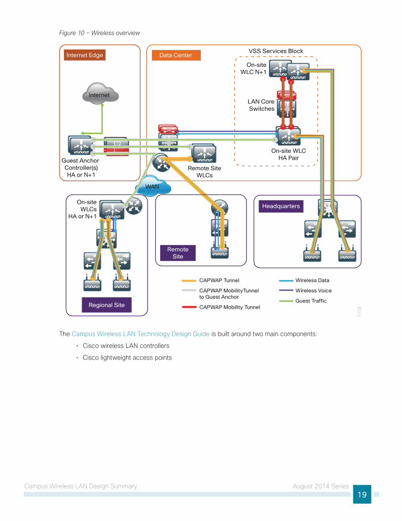
Figure 10 - Wireless overview
VSS Services Block
On-site WLCHA Pair
On-siteWLC N+1
WAN
RemoteSite
LAN CoreSwitches
11
78Regional Site
Internet Edge Data Center
Headquarters
Internet
Remote SiteWLCs
On-siteWLCs
HA or N+1
Guest Anchor Controller(s)HA or N+1
CAPWAP Tunnel
CAPWAP MobilityTunnel to Guest Anchor
CAPWAP Mobility Tunnel
Wireless Data
Wireless Voice
Guest Traffic
The Campus Wireless LAN Technology Design Guide is built around two main components:
• Cisco wireless LAN controllers
• Cisco lightweight access points
Campus Wireless LAN Design Summary August 2014 Series20
Cisco Wireless LAN ControllersThe Campus Wireless LAN Technology Design Guide is a controller-based wireless design, which simplifies network management by using Cisco wireless LAN controllers (WLCs) to centralize the configuration and control of wireless access points. This approach allows the wireless LAN (WLAN) to operate as an intelligent information network and to support advanced services. The following are some of the benefits of the controller-based design:
• Lower operational expenses—Enables zero-touch configurations for lightweight access points; easy design of channel and power settings and real-time management, including identifying any RF holes in order to optimize the RF environment; seamless mobility across the various access points within the mobility group; and a holistic view of the network, supporting decisions about scale, security, and overall operations.
• Improved return on investment—Enables virtualized instances of the wireless LAN controller, reducing the total cost of ownership by leveraging their investment in virtualization.
• Easier way to scale with optimal design—Enables the network to scale well, by supporting a local-mode design for campus environments and Cisco FlexConnect design for lean remote sites.
• High availability stateful switchover—Enables non-disruptive connectivity to wireless client devices during a wireless LAN controller failure.
Cisco wireless LAN controllers are responsible for system-wide WLAN functions, such as security policies, intrusion prevention, RF management, quality of service (QoS), and mobility. They work in conjunction with Cisco lightweight access points to support business-critical wireless applications. From voice and data services to location tracking, Cisco wireless LAN controllers provide the control, scalability, security, and reliability that network managers need to build secure, scalable wireless networks.
Although a standalone controller can support lightweight access points across multiple floors and buildings simultaneously, you should deploy controllers in pairs for resiliency. There are many different ways to configure controller resiliency; the simplest is to use a primary/secondary model where all the access points at the site prefer to join the primary controller and only join the secondary controller during a failure event.
The following controllers are included in the Campus Wireless LAN Technology Design Guide:
• Cisco 2500 Series Wireless LAN Controller
• Cisco 5500 Series Wireless LAN Controller
• Cisco Wireless Services Module 2 (WiSM2)
• Cisco 5760 Series Wireless LAN Controller
• Cisco Virtual Wireless LAN Controller
• Cisco Flex 7500 Series Cloud Controller
Because software license flexibility allows you to add additional access points as business requirements change, you can choose the controller that will support your needs long-term, but you purchase incremental access-point licenses only when you need them.
Campus Wireless LAN Design Summary August 2014 Series21
Cisco Lightweight Access PointsIn the Cisco Unified Wireless Network architecture, access points are lightweight. This means they cannot act independently of a wireless LAN controller. As the access point communicates with the wireless LAN controller, it downloads its configuration and synchronize its software or firmware image.
Cisco lightweight access points work in conjunction with a Cisco wireless LAN controller to connect wireless devices to the LAN while supporting simultaneous data-forwarding and air-monitoring functions. The Campus Wireless LAN Technology Design Guide is based on Cisco Generation 2 wireless access points, which offer robust wireless coverage with up to nine times the throughput of 802.11a/b/g networks. The following access points are included in the Campus Wireless LAN Technology Design Guide:
• Cisco Aironet 1600 Series Access Points
• Cisco Aironet 2600 Series Access Points
• Cisco Aironet 3600 Series Access Points
• Cisco Aironet 3700 Series Access Points
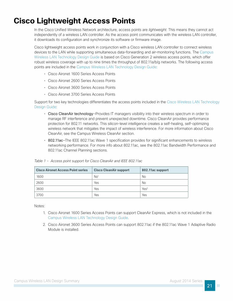
Support for two key technologies differentiates the access points included in the Cisco Wireless LAN Technology Design Guide:
• Cisco CleanAir technology—Provides IT managers visibility into their wireless spectrum in order to manage RF interference and prevent unexpected downtime. Cisco CleanAir provides performance protection for 802.11 networks. This silicon-level intelligence creates a self-healing, self-optimizing wireless network that mitigates the impact of wireless interference. For more information about Cisco CleanAir, see the Campus Wireless CleanAir section.
• 802.11ac—The IEEE 802.11ac Wave 1 specification provides for significant enhancements to wireless networking performance. For more info about 802.11ac, see the 802.11ac Bandwidth Performance and 802.11ac Channel Planning sections.
Table 1 - Access point support for Cisco CleanAir and IEEE 802.11ac
Cisco Aironet Access Point series Cisco CleanAir support 802.11ac support
1600 No1 No
2600 Yes No
3600 Yes Yes2
3700 Yes Yes
Notes:
1. Cisco Aironet 1600 Series Access Points can support CleanAir Express, which is not included in the Campus Wireless LAN Technology Design Guide.
2. Cisco Aironet 3600 Series Access Points can support 802.11ac if the 802.11ac Wave 1 Adaptive Radio Module is installed.
Campus Wireless LAN Design Summary August 2014 Series22
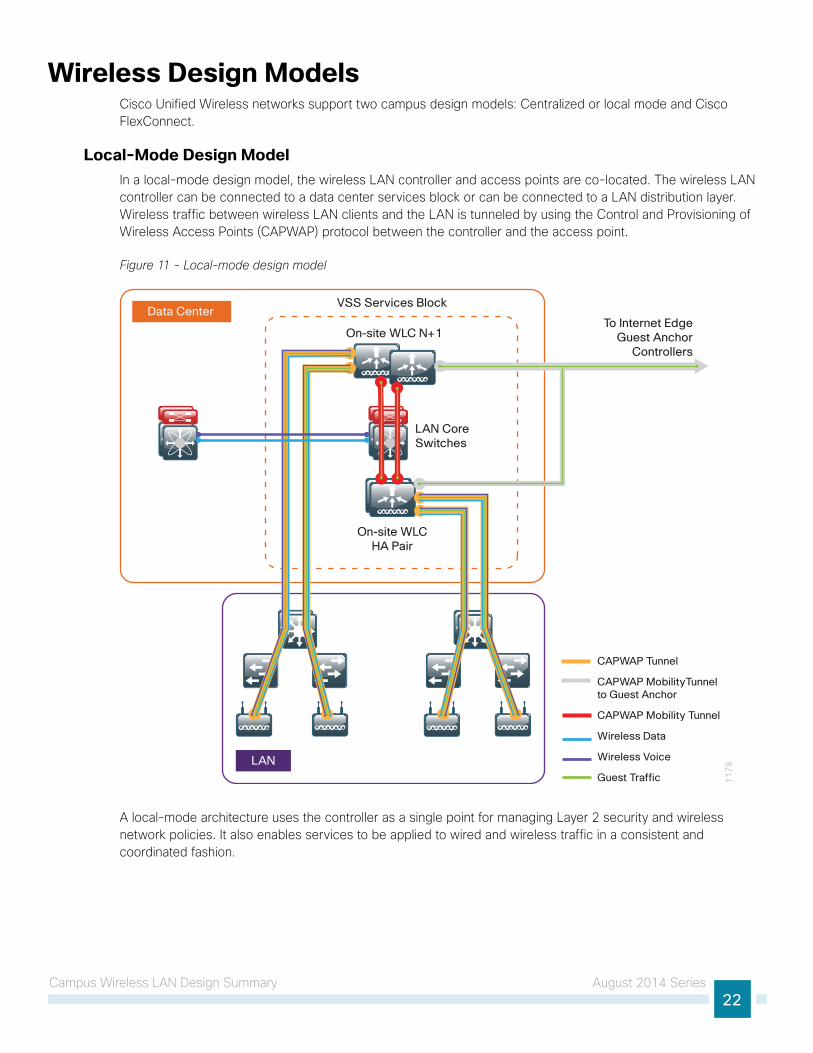
Wireless Design ModelsCisco Unified Wireless networks support two campus design models: Centralized or local mode and Cisco FlexConnect.
Local-Mode Design Model In a local-mode design model, the wireless LAN controller and access points are co-located. The wireless LAN controller can be connected to a data center services block or can be connected to a LAN distribution layer. Wireless traffic between wireless LAN clients and the LAN is tunneled by using the Control and Provisioning of Wireless Access Points (CAPWAP) protocol between the controller and the access point.
Figure 11 - Local-mode design model
11
79LAN
VSS Services Block
On-site WLC N+1
LAN CoreSwitches
Data Center
On-site WLCHA Pair
To Internet EdgeGuest Anchor
Controllers
CAPWAP Tunnel
CAPWAP MobilityTunnel to Guest Anchor
CAPWAP Mobility Tunnel
Wireless Data
Wireless Voice
Guest Traffic
A local-mode architecture uses the controller as a single point for managing Layer 2 security and wireless network policies. It also enables services to be applied to wired and wireless traffic in a consistent and coordinated fashion.
Campus Wireless LAN Design Summary August 2014 Series23
In addition to providing the traditional benefits of a Cisco Unified Wireless Network approach, the local-mode design model meets the following customer demands:
• Seamless mobility—Enables fast roaming across the campus, so that users remain connected to their session even while walking between various floors or adjacent buildings with changing subnets
• Ability to support rich media—Enhances robustness of voice with Call Admission Control (CAC) and multicast with Cisco VideoStream technology.
• Centralized policy—Enables intelligent inspection through the use of firewalls, as well as application inspection, network access control, policy enforcement, and accurate traffic classification.
If any of the following are true at a site, you should deploy a controller locally at the site:
• The site has a data center.
• The site has a LAN distribution layer.
• The site has more than 50 access points.
• The site has a WAN latency greater than 100 ms round-trip to a proposed shared controller.
In a deployment with these characteristics, use a Cisco 2500, 5500, WiSM2 or 5700 Series Wireless LAN Controller. For resiliency, the Campus Wireless LAN Technology Design Guide uses two or more wireless LAN controllers for the campus. Additional wireless LAN controllers can be added in order to provide additional capacity and resiliency to this design.
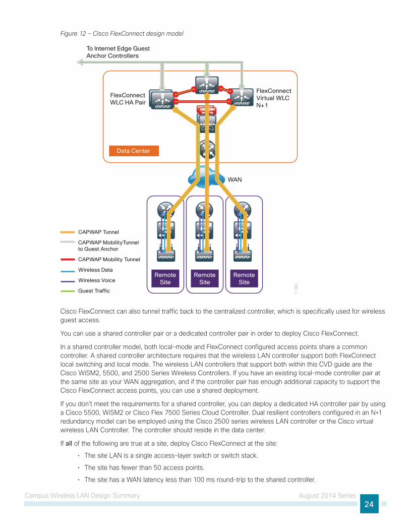
Cisco FlexConnect Design ModelCisco FlexConnect is a wireless solution for remote-site deployments. It enables organizations to configure and control remote-site access points from the headquarters through the WAN, without deploying a controller in each remote site. The Cisco FlexConnect access point can switch client data traffic out its local wired interface and can use 802.1Q trunking in order to segment multiple WLANs. The trunk’s native VLAN is used for all CAPWAP communication between the access point and the controller. This mode of operation is referred to as FlexConnect local switching and is the mode of operation described in this guide.
Campus Wireless LAN Design Summary August 2014 Series24
Figure 12 - Cisco FlexConnect design model
11
80
WAN
RemoteSite
RemoteSite
RemoteSite
FlexConnectWLC HA Pair
FlexConnectVirtual WLCN+1
Data Center
To Internet Edge GuestAnchor Controllers
CAPWAP Tunnel
CAPWAP MobilityTunnel to Guest Anchor
CAPWAP Mobility Tunnel
Wireless Data
Wireless Voice
Guest Traffic
Cisco FlexConnect can also tunnel traffic back to the centralized controller, which is specifically used for wireless guest access.
You can use a shared controller pair or a dedicated controller pair in order to deploy Cisco FlexConnect.
In a shared controller model, both local-mode and FlexConnect configured access points share a common controller. A shared controller architecture requires that the wireless LAN controller support both FlexConnect local switching and local mode. The wireless LAN controllers that support both within this CVD guide are the Cisco WiSM2, 5500, and 2500 Series Wireless Controllers. If you have an existing local-mode controller pair at the same site as your WAN aggregation, and if the controller pair has enough additional capacity to support the Cisco FlexConnect access points, you can use a shared deployment.
If you don’t meet the requirements for a shared controller, you can deploy a dedicated HA controller pair by using a Cisco 5500, WiSM2 or Cisco Flex 7500 Series Cloud Controller. Dual resilient controllers configured in an N+1 redundancy model can be employed using the Cisco 2500 series wireless LAN controller or the Cisco virtual wireless LAN Controller. The controller should reside in the data center.
If all of the following are true at a site, deploy Cisco FlexConnect at the site:
• The site LAN is a single access-layer switch or switch stack.
• The site has fewer than 50 access points.
• The site has a WAN latency less than 100 ms round-trip to the shared controller.
Campus Wireless LAN Design Summary August 2014 Series25
High AvailabilityAs mobility continues to increase its influence in all aspects of our personal and professional lives, availability continues to be a top concern. The Campus Wireless LAN Technology Design Guide supports high availability through the use of resilient controllers within a common mobility group.
Cisco AireOS supports access-point Stateful Switchover and client Stateful Switchover . These two features are collectively referred to as high availability SSO (HA SSO). By using the cost-effective HA-SSO licensing model, Cisco wireless deployments can improve the availability of the wireless network with controller recovery times in the sub-second range during a wireless LAN controller disruption. In addition, HA SSO allows the resilient wireless LAN controller to be cost-effectively licensed as a standby resilient controller with its access-point license count automatically inherited from its paired primary wireless LAN controller. This is accomplished by purchasing a standby resilient controller using the HA SKU available for the Cisco 5500, 7500 and WiSM2 Series wireless LAN controllers. Support for HA SSO within the WiSM2 controller family requires that both WiSM2 wireless LAN controllers are deployed in one of the following ways:
• Within a Cisco Catalyst 6807-XL or 6500 Series Switch pair configured for VSS operation.
• Within the same Cisco Catalyst 6807-XL or 6500 Series Switch chassis.
• Within a different Cisco Catalyst 6807-XL or 6500 Series Switch chassis when the Layer 2 redundancy VLAN is extended.
The configuration and software upgrades of the primary wireless LAN controller are automatically synchronized to the resilient standby wireless LAN controller.
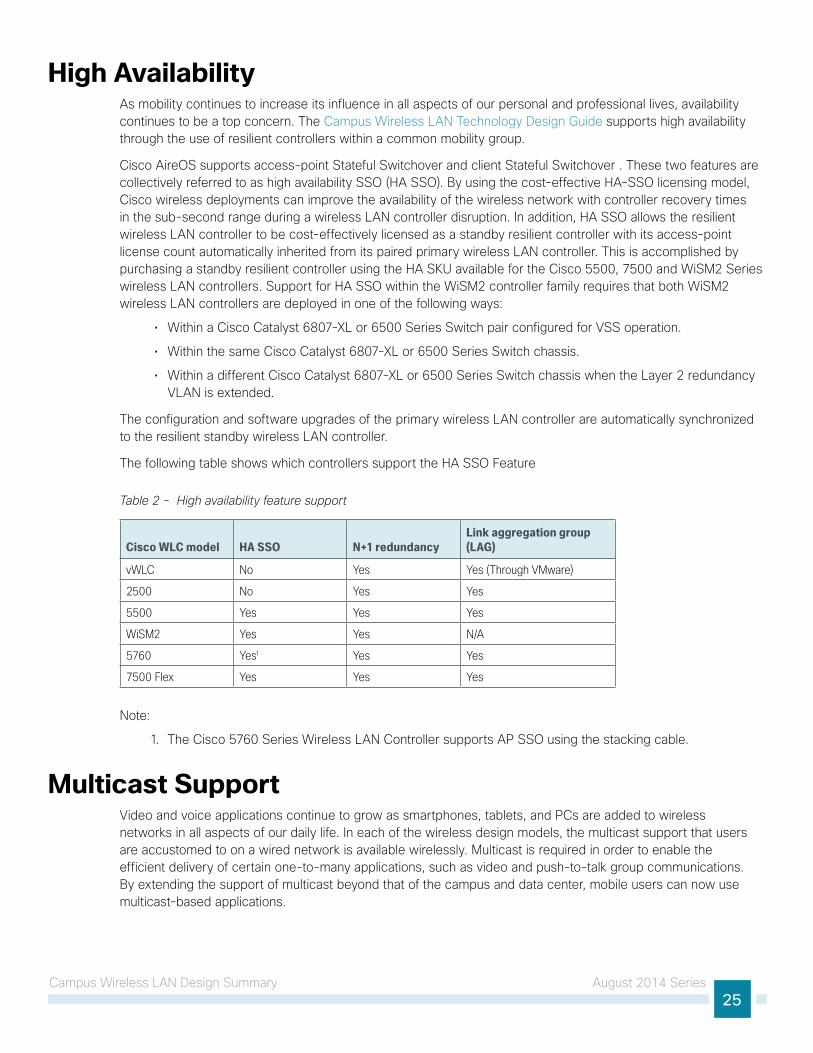
The following table shows which controllers support the HA SSO Feature
Table 2 - High availability feature support
Cisco WLC model HA SSO N+1 redundancyLink aggregation group (LAG)
vWLC No Yes Yes (Through VMware)
2500 No Yes Yes
5500 Yes Yes Yes
WiSM2 Yes Yes N/A
5760 Yes1 Yes Yes
7500 Flex Yes Yes Yes
Note:
1. The Cisco 5760 Series Wireless LAN Controller supports AP SSO using the stacking cable.
Multicast SupportVideo and voice applications continue to grow as smartphones, tablets, and PCs are added to wireless networks in all aspects of our daily life. In each of the wireless design models, the multicast support that users are accustomed to on a wired network is available wirelessly. Multicast is required in order to enable the efficient delivery of certain one-to-many applications, such as video and push-to-talk group communications. By extending the support of multicast beyond that of the campus and data center, mobile users can now use multicast-based applications.

Campus Wireless LAN Design Summary August 2014 Series26
The Campus Wireless LAN Technology Design Guide supports multicast transmission for the onsite controller through the use of multicast-multicast mode, which uses a multicast IP address in order to more efficiently communicate multicast streams to access points that have wireless users subscribing to a particular multicast group. Multicast-multicast mode is supported on in this CVD using the Cisco 2500, 5500, WiSM2 and 5760 Series Wireless LAN Controllers.
Remote sites that use the Cisco Flex 7500 Series Cloud Controller or Cisco vWLC using Cisco FlexConnect in local switching mode can also benefit from the use of multicast-based applications. Multicast in remote sites leverage the underlying WAN and LAN support of multicast traffic. When combined with access points in FlexConnect mode using local switching, subscribers to multicast streams are serviced directly over the WAN or LAN network with no additional overhead being placed on the wireless LAN controller.
Band SelectOver time with the advent of consumer devices operating in the 2.4-GHz industrial, scientific and medical band, the level of noise resulting in interference in this band has grown considerably. Likewise, many of the wireless devices available today are dual band and can operate in either the 2.4-GHz or 5-GHz band.
With critical business-class devices, it would be advantageous to influence these devices to utilize the 5-GHz band with the objective of much lower interference and therefore a better user experience.
When dual-band wireless devices look for an access point, they often first send a probe request on the 2.4-GHz band and then send out a probe request on the 5-GHz band a few milliseconds later. Because the 2.4-GHz probe response is typically received first, many devices connect using the 2.4-GHz band even though a 5-GHz access point is available.
Band Select delays the probe response to the 2.4-GHz probe by a few hundred milliseconds, allowing the access point to determine if the wireless device is a dual-band device. A dual-band wireless device is detected when a 2.4-GHz and 5-GHz probe is received from the same device. By delaying the 2.4-GHz probe response and providing the 5-GHz probe response prior to the 2.4-GHz probe response, it is possible to influence the wireless client to connect to the preferred 5-GHz band.
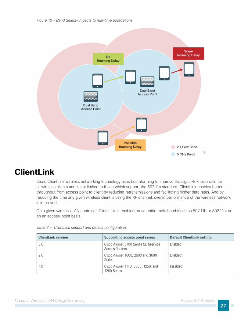
Band Select for voice and video devices is not recommended because it introduces delay in responding to probe requests in the 2.4-GHz band. For real-time streaming devices that are moving from a 5-GHz area into a 2.4-GHz covered area, or clients that are roaming between 2.4-GHz access points, this delay could result in momentary disruption of connectivity. With data-only traffic flows, this delay is negligible and generally does not impact application access.
Campus Wireless LAN Design Summary August 2014 Series27
Figure 13 - Band Select—Impacts to real-time applications
Dual BandAccess Point
Dual BandAccess Point
2.4 GHz Band
5 GHz Band 11
81
Possible Roaming Delay
Some Roaming DelayNo
Roaming Delay
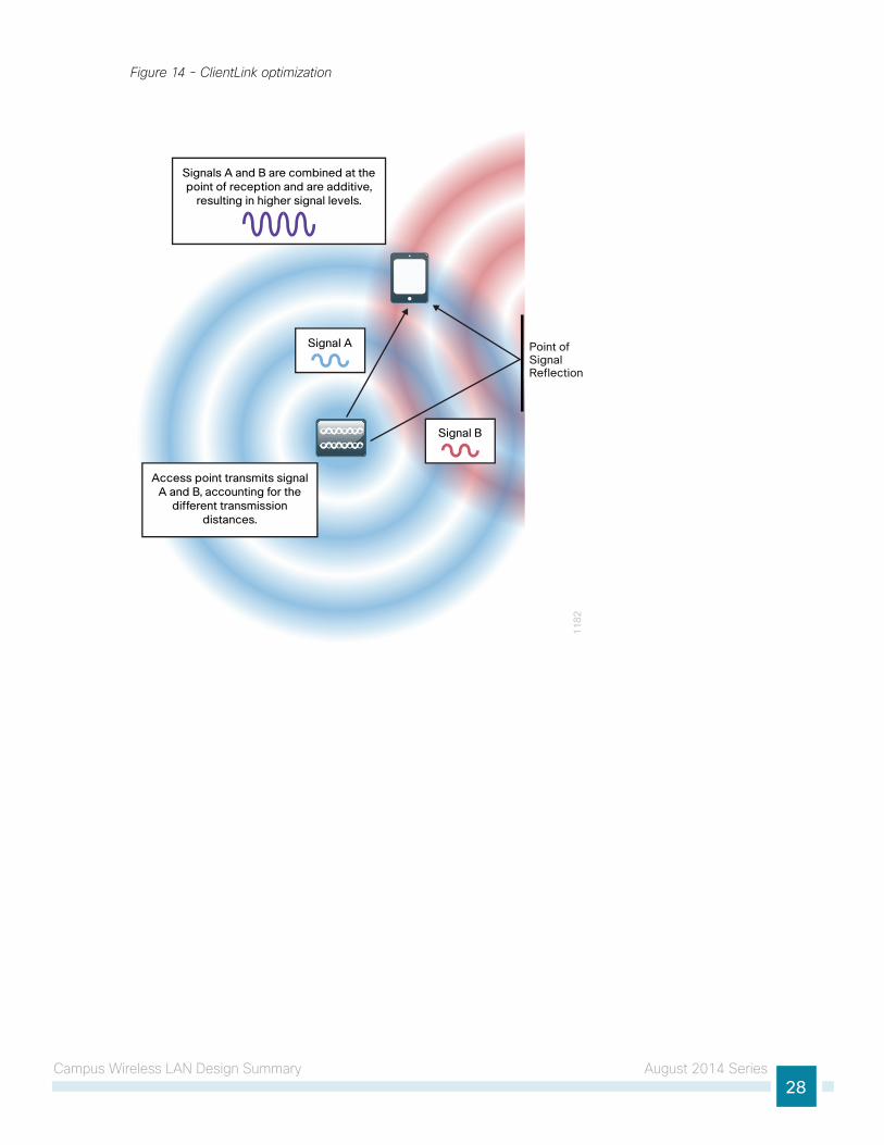
ClientLinkCisco ClientLink wireless networking technology uses beamforming to improve the signal-to-noise ratio for all wireless clients and is not limited to those which support the 802.11n standard. ClientLink enables better throughput from access point to client by reducing retransmissions and facilitating higher data rates. And by reducing the time any given wireless client is using the RF channel, overall performance of the wireless network is improved.
On a given wireless LAN controller, ClientLink is enabled on an entire radio band (such as 802.11b or 802.11a) or on an access-point basis.
Table 3 - ClientLink support and default configuration
ClientLink version Supporting access point series Default ClientLink setting
3.0 Cisco Aironet 3700 Series Multiservice Access Routers
Enabled
2.0 Cisco Aironet 1600, 2600 and 3600 Series
Enabled
1.0 Cisco Aironet 1140, 3500, 1250, and 1260 Series
Disabled
Campus Wireless LAN Design Summary August 2014 Series28
Figure 14 - ClientLink optimization
11
82
Point of Signal Reflection
Signal B
Signals A and B are combined at the point of reception and are additive,
resulting in higher signal levels.
Signal A
Access point transmits signal A and B, accounting for the
different transmission distances.

Campus Wireless LAN Design Summary August 2014 Series29
802.11ac Bandwidth PerformanceThere has been no other time in the evolution of Wi-Fi based wireless technology that has seen such significant performance improvements than with the introduction of 802.11ac. Beginning in 1997 the original 802.11 standard yielded a theoretical physical layer (PHY) performance of 2 Mbps. Today, with the introduction of 802.11ac Wave 1 with 3 Spatial Streams (3SS), the theoretical maximum PHY performance jumps to 1.3 Gbps.
Table 4 - 802.11ac Bandwidth performance
Year Technology Theoretical PHY performance Expected user performance
1997 802.11 2 Mbps 1 Mbps
1999 802.11b 11 Mbps 6 Mbps
1999 802.11a 54 Mbps 25 Mbps
2003 802.11g 54 Mbps 25 Mbps
2003 802.11a/g 54 Mbps 13-25 Mbps
2007 802.11n 450 Mbps w/ 3SS 180-220 Mbps
2013 802.11ac Wave 1 1.3Gbps w/ 3SS up to 750 Mbps
Future 802.11ac Wave 2 2.4-3.5 Gbps To be determined
Actual wireless performance is a function of a number of variables, such as distance, wireless adapter, and the overall RF environment. Additionally, adjacent mixed cells using 802.11a can result in longer channel usage due to lower transmit speed. When 40 MHz bonded adjacent 802.11a/n is deployed with misaligned primary channel, the benefits of the Clear Carrier Assessment mechanism are not realized.
The 802.11ac Wave 1 specification includes a number of technologies, as detailed in the following, which are responsible for this significant performance improvement.
• 802.11ac is implemented only in the quieter and less crowded 5 GHz band.
• 802.11ac employs a 256 Quadrature Amplitude Modulation (QAM), allowing 8 bits per symbol and a fourfold increase in performance. In simplest terms, QAM is a modulation technique that uses waveform phase and amplitude to encode data. With 256 QAM, there are 256 symbols, resulting in higher throughput.
• 802.11ac expands channel widths, to allow widths of 20, 40, and 80 MHz in Wave 1; and widths of 20, 40, 80, 80+80, and 160 MHz in Wave 2.
• Beamforming, enhanced in 802.11ac Wave 1 and included in Cisco ClientLink wireless networking technology, allows the access point to beam steer or direct a concentration of signals at the receiver that combine to increase the quality and signal level at the receiver. In Wave 2, multi-user beamforming allows a single access point to transmit to 4 wireless clients at the same time and on the same frequency, allowing each client to have its own dedicated spatial stream.
802.11ac Channel PlanningChannel assignment when using Radio Resource Management (RRM) and Dynamic Channel Assignment (DCA) is simpler then it was in the early days of 802.11. Even so, there are some things to consider before making the decision to bond channels. While the Campus Wireless LAN Technology Design Guide assumes a greenfield deployment, network administrators of existing wireless environments may want to move more cautiously and ensure that channel-planning considerations are addressed.

Campus Wireless LAN Design Summary August 2014 Series30
If your environment is limited to the standard 20-MHz-wide channels, Cisco recommends a phased approach for switching to 80-MHz-wide channels. The initial step is to enable a Dynamic Frequency Selection (DFS) channel set. Using DFS channels requires that the access point scans for the use of radar. If radar is detected, the access point moves to another channel or reduces the transmit power. DFS channels enable a wider range of RF spectrum, subject to your regulatory domain. This in turn enables greater channel-bonding choices by DCA.
With DFS channels enabled, four 80-MHz channels and eight 40-MHz channels are available in the U.S.
Table 5 - Worldwide 5GHz channel availability
Number of channels available U.S. EU China India Japan Russia
20MHz channels 18 16 5 13 19 16
40MHz channels 8 8 2 6 9 8
80MHz channels 4 4 1 3 4 4
With the advent of 80MHz-wide channels in 802.11ac Wave 1, and the upcoming 160MHz wide channels in Wave 2, there are some considerations regarding channel planning. The number of 20 MHz channels in the 5 GHz band is plentiful, but this can quickly change as 80 MHz and 160 MHz (Wave 2) are deployed within the enterprise. Figure 15 explains the effects of 40 MHz and 80 MHz channel selections.
Figure 15 - Channel usage in the U.S.
11
83
20 MHz
40MHz
80 MHz
160MHz
5250MHz
Available
Not Yet Available
To Become Available
Special OOBE Must Be Met
14
91
53
15
71
61
16
51
69
17
31
77
18
1
36
40
44
48
52
56
60
64
68
72
76
80
84
88
92
96
10
01
04
10
81
12
11
61
20
12
41
28
13
21
36
14
01
44
Channel #
5350MHz
5470MHz
5725MHz
5825MHz
5925MHz
UNII-1 UNII-2 UNII-2 Extended UNII-3
With RRM, Transmit Power Control (TPC), and DCA, the process of channel selection can be both automated and optimized.
Campus Wireless LAN Design Summary August 2014 Series31
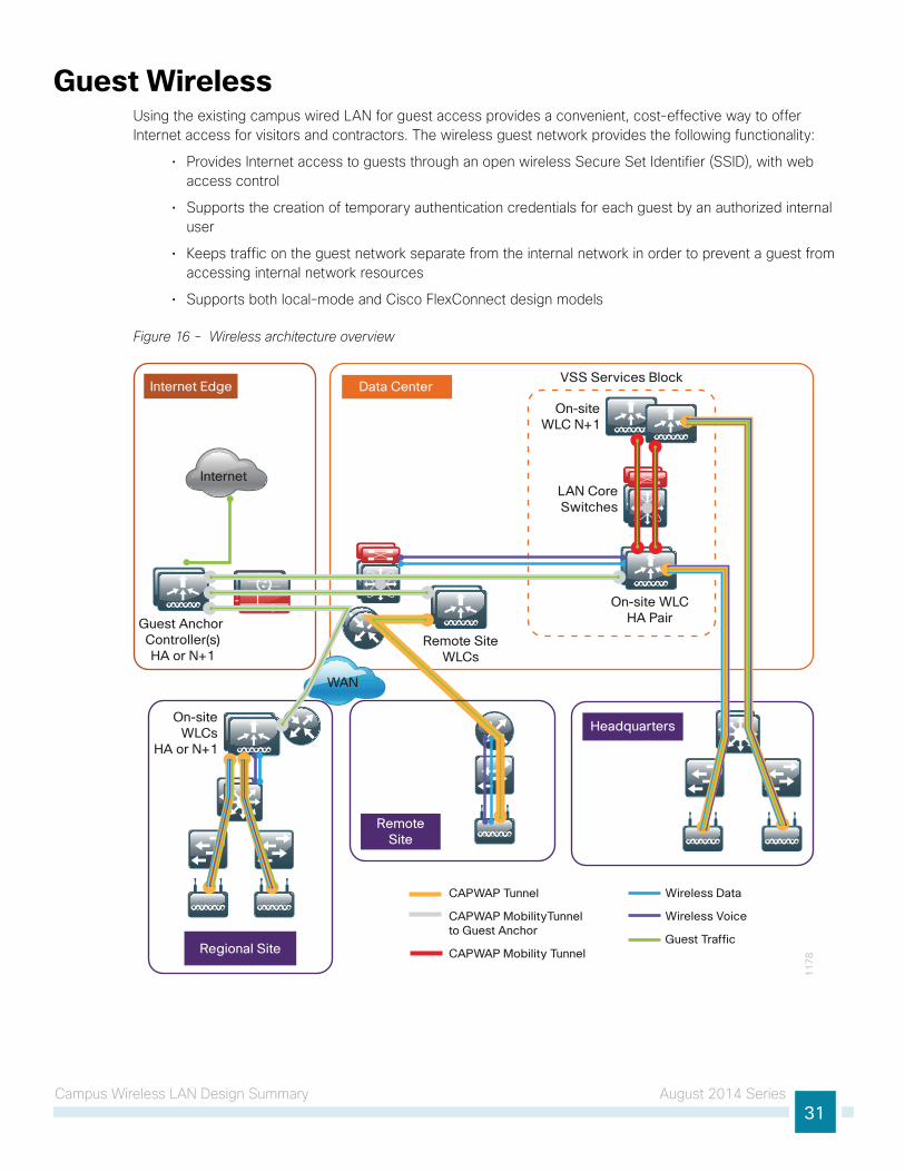
Guest WirelessUsing the existing campus wired LAN for guest access provides a convenient, cost-effective way to offer Internet access for visitors and contractors. The wireless guest network provides the following functionality:
• Provides Internet access to guests through an open wireless Secure Set Identifier (SSID), with web access control
• Supports the creation of temporary authentication credentials for each guest by an authorized internal user
• Keeps traffic on the guest network separate from the internal network in order to prevent a guest from accessing internal network resources
• Supports both local-mode and Cisco FlexConnect design models
Figure 16 - Wireless architecture overview
VSS Services Block
On-site WLCHA Pair
On-siteWLC N+1
WAN
RemoteSite
LAN CoreSwitches
11
78Regional Site
Internet Edge Data Center
Headquarters
Internet
Remote SiteWLCs
On-siteWLCs
HA or N+1
Guest Anchor Controller(s)HA or N+1
CAPWAP Tunnel
CAPWAP MobilityTunnel to Guest Anchor
CAPWAP Mobility Tunnel
Wireless Data
Wireless Voice
Guest Traffic

Campus Wireless LAN Design Summary August 2014 Series32
Both shared controller and dedicated controller pair deployment models within the Internet edge demilitarized zone (DMZ) are supported for wireless guest services within this CVD guide.
If you have a single controller pair for the entire organization and that controller pair is connected to the same distribution switch as the Internet edge firewall, you can use a shared deployment.
In a shared deployment, a VLAN is created on the distribution switch in order to logically connect guest traffic from the wireless LAN controllers to the DMZ. The DMZ Guest VLAN will not have an associated Layer 3 interface or switch virtual interface. As such, each wireless client on the guest network will use the Internet edge firewall as their default gateway.
If you don’t meet the requirements for a shared deployment, you can use Cisco 5500 or Cisco 2500 Series Wireless LAN Controllers in order to deploy a dedicated guest controller. The controller is directly connected the Internet edge DMZ, and guest traffic from every other controller in the organization is tunneled to this controller. Other controllers such as Cisco WiSM2 and Cisco 5760 Series Wireless LAN Controllers can provide guest anchoring services as described, but most organizations will use other wireless LAN controller models and therefore these deployment models are not covered in this guide.
In both the shared and dedicated guest wireless design models, the Internet edge firewall restricts access from the guest network. The guest network is only able to reach the Internet and the internal DHCP and DNS servers.
This guide covers the use of the Cisco 5760 Series Wireless LAN Controller as an onsite centralized campus wireless LAN controller. The Cisco 5760 Unified Access Wireless LAN Controller can be deployed in a number of different models. With the introduction of Converged Access, a number of new features such as Mobility Controller (MC), Mobility Agent (MA), and Mobility Oracle (MO) have also been introduced.
The deployment model used in this CVD guide for the Cisco 5760 Series Wireless LAN Controller is similar to that of Cisco AireOS, namely Cisco Unified Wireless Network (CUWN). In the CUWN architecture, controllers maintain both the MC and MA functions on the controller. Future versions will begin to separate these functions in order to provide additional scaling capabilities. This approach is consistent with many deployments of the Cisco 5760 Series Wireless LAN Controller with the intention of moving the MA onto Cisco Catalyst 3850/3650 Series Switches as the access layer switches are upgraded.
Additional Wireless LAN Designs August 2014 Series33
Additional Wireless LAN DesignsValidated in the Campus Wireless LAN Technology Design Guide environment, the Campus Wireless CleanAir Technology Design Guide helps mitigate RF interference in your wireless LAN while the Cisco OfficeExtend Technology Design Guide helps enable teleworker success.
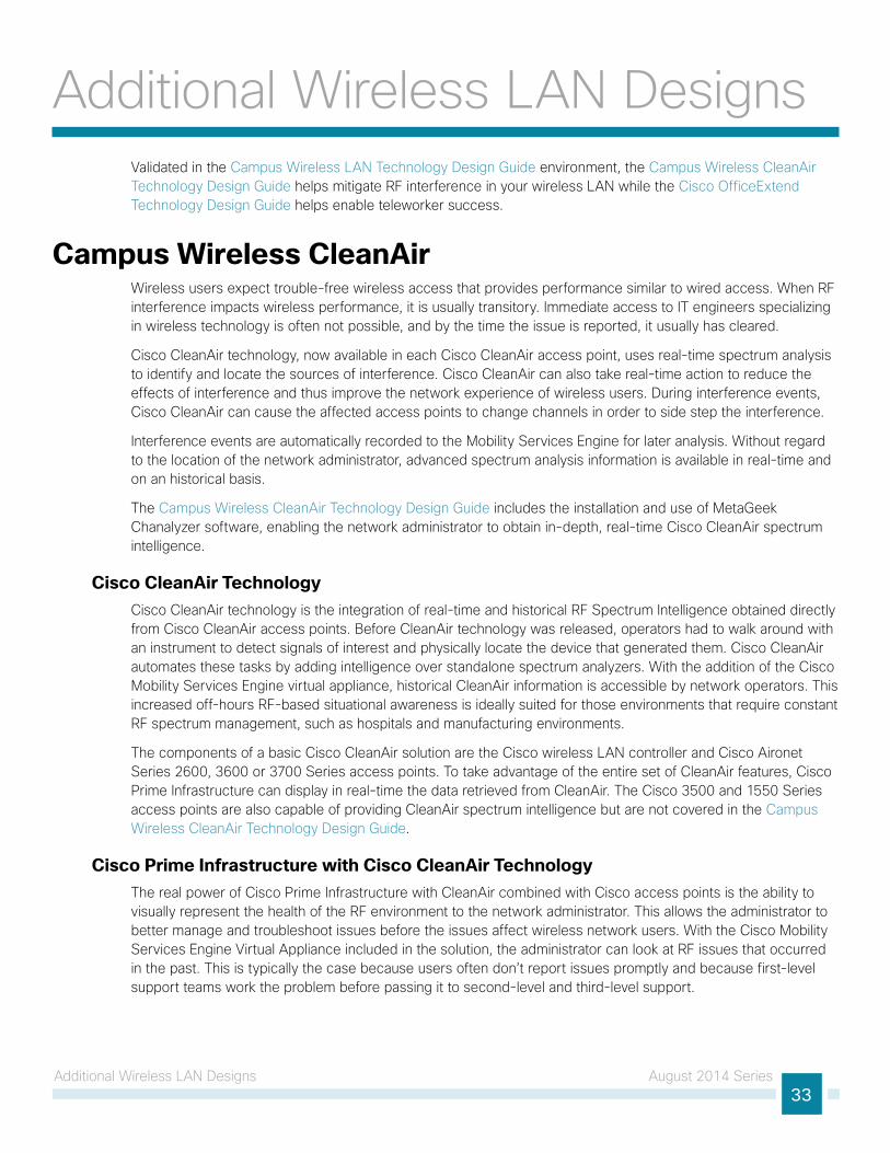
Campus Wireless CleanAirWireless users expect trouble-free wireless access that provides performance similar to wired access. When RF interference impacts wireless performance, it is usually transitory. Immediate access to IT engineers specializing in wireless technology is often not possible, and by the time the issue is reported, it usually has cleared.
Cisco CleanAir technology, now available in each Cisco CleanAir access point, uses real-time spectrum analysis to identify and locate the sources of interference. Cisco CleanAir can also take real-time action to reduce the effects of interference and thus improve the network experience of wireless users. During interference events, Cisco CleanAir can cause the affected access points to change channels in order to side step the interference.
Interference events are automatically recorded to the Mobility Services Engine for later analysis. Without regard to the location of the network administrator, advanced spectrum analysis information is available in real-time and on an historical basis.
The Campus Wireless CleanAir Technology Design Guide includes the installation and use of MetaGeek Chanalyzer software, enabling the network administrator to obtain in-depth, real-time Cisco CleanAir spectrum intelligence.
Cisco CleanAir TechnologyCisco CleanAir technology is the integration of real-time and historical RF Spectrum Intelligence obtained directly from Cisco CleanAir access points. Before CleanAir technology was released, operators had to walk around with an instrument to detect signals of interest and physically locate the device that generated them. Cisco CleanAir automates these tasks by adding intelligence over standalone spectrum analyzers. With the addition of the Cisco Mobility Services Engine virtual appliance, historical CleanAir information is accessible by network operators. This increased off-hours RF-based situational awareness is ideally suited for those environments that require constant RF spectrum management, such as hospitals and manufacturing environments.
The components of a basic Cisco CleanAir solution are the Cisco wireless LAN controller and Cisco Aironet Series 2600, 3600 or 3700 Series access points. To take advantage of the entire set of CleanAir features, Cisco Prime Infrastructure can display in real-time the data retrieved from CleanAir. The Cisco 3500 and 1550 Series access points are also capable of providing CleanAir spectrum intelligence but are not covered in the Campus Wireless CleanAir Technology Design Guide.
Cisco Prime Infrastructure with Cisco CleanAir TechnologyThe real power of Cisco Prime Infrastructure with CleanAir combined with Cisco access points is the ability to visually represent the health of the RF environment to the network administrator. This allows the administrator to better manage and troubleshoot issues before the issues affect wireless network users. With the Cisco Mobility Services Engine Virtual Appliance included in the solution, the administrator can look at RF issues that occurred in the past. This is typically the case because users often don’t report issues promptly and because first-level support teams work the problem before passing it to second-level and third-level support.

Additional Wireless LAN Designs August 2014 Series34
Cisco Prime Infrastructure with Cisco CleanAir technology allows network administrators to see how well their wireless network is performing, remotely troubleshoot client connectivity, manage wireless network resources, analyze interference devices, and more. For more information about Cisco Prime Infrastructure, see the Cisco Prime Infrastructure section.
The Campus Wireless CleanAir Technology Design Guide is available at www.cisco.com/go/cvd/campus
Cisco OfficeExtendFor the home-based teleworker, it is critical that access to business services be reliable and consistent, providing an experience that is comparable to being on campus. But on the commonly used 2.4-GHz wireless band, residential and urban environments have many potential sources of congestion, such as cordless handsets, smartphones, tablets, and baby monitors. To support users whose technical skills vary widely, a teleworker solution must provide a streamlined and simplified way to implement devices that allow for secure access to the corporate environment.
IT operations have a different set of challenges when it comes to implementing a teleworking solution, including properly securing, maintaining, and managing the teleworker environment from a centralized location. Because operational expenses are a constant consideration, IT must implement a cost-effective solution that protects an organization’s investment without sacrificing quality or functionality.
The Cisco OfficeExtend Technology Design Guide satisfies the ease-of-use, quality-of-experience, and operational-cost requirements. The Cisco OfficeExtend solution is built around two main components:
• Cisco 2500 Series or Cisco 5500 Series Wireless LAN Controller
• Cisco Aironet 600 Series OfficeExtend Access Point
Cisco Wireless LAN ControllersCisco wireless LAN controllers work in conjunction with Cisco OfficeExtend Access Points to support business-critical wireless applications for teleworkers. Cisco wireless LAN controllers provide the control, scalability, security, and reliability that network managers need to build a secure, scalable teleworker environment.
A standalone controller can support up to 500 Cisco OfficeExtend sites. For a resilient solution, Cisco recommends deploying controllers in pairs.
The following controllers are included in Cisco OfficeExtend Technology Design Guide:
• Cisco 2500 Series Wireless LAN Controller
• Cisco 5500 Series Wireless LAN Controller
Because software license flexibility allows you to add additional access points as business requirements change, you can choose the controller that will support your needs long-term, but only pay for what you need, when you need it.
To allow users to connect their endpoint devices to either the organization’s on-site wireless network or their at-home teleworking wireless networks without reconfiguration, the Cisco OfficeExtend Technology Design Guide uses the same wireless SSIDs at teleworkers’ homes as those that support data and voice inside the organization.
Additional Wireless LAN Designs August 2014 Series35
Cisco OfficeExtend Access PointsThe Cisco Aironet 600 Series OfficeExtend Access Point is lightweight, meaning it cannot act independently of a wireless LAN controller. To offer remote WLAN connectivity using the same profile as at the corporate office, the access point validates all traffic against centralized security policies. By using wireless LAN controllers for the centralization of policies, Cisco OfficeExtend minimizes the management overhead associated with home-based firewalls. Communications between the access point and the wireless LAN controller are secured by a Datagram Transport Layer Security (DTLS) connection.
Cisco OfficeExtend delivers full 802.11n wireless performance and avoids congestion caused by residential devices because it operates simultaneously in the 2.4-GHz and the 5-GHz radio frequency bands. The access point also provides wired Ethernet connectivity in addition to wireless. The Cisco OfficeExtend Access Point provides wired and wireless segmentation of home and corporate traffic, which allows for home device connectivity without introducing security risks to corporate policy.
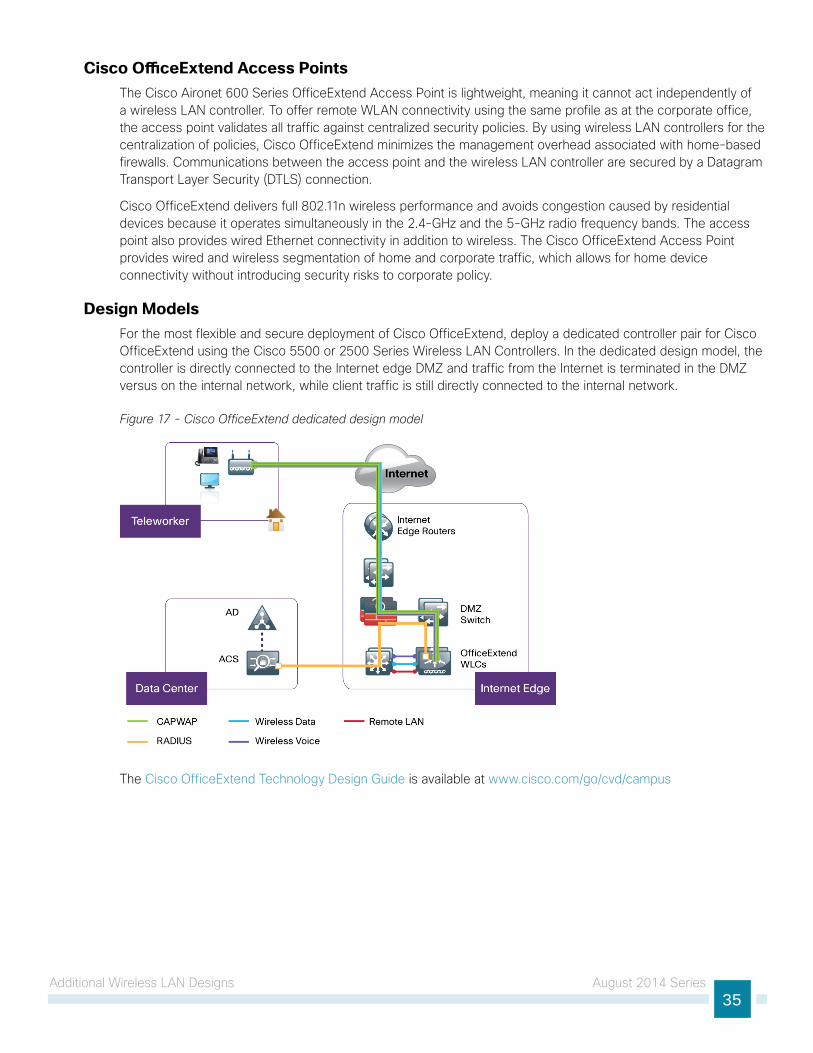
Design ModelsFor the most flexible and secure deployment of Cisco OfficeExtend, deploy a dedicated controller pair for Cisco OfficeExtend using the Cisco 5500 or 2500 Series Wireless LAN Controllers. In the dedicated design model, the controller is directly connected to the Internet edge DMZ and traffic from the Internet is terminated in the DMZ versus on the internal network, while client traffic is still directly connected to the internal network.
Figure 17 - Cisco OfficeExtend dedicated design model
The Cisco OfficeExtend Technology Design Guide is available at www.cisco.com/go/cvd/campus
Americas HeadquartersCisco Systems, Inc.San Jose, CA
Asia Pacific HeadquartersCisco Systems (USA) Pte. Ltd.Singapore
Europe HeadquartersCisco Systems International BV Amsterdam,The Netherlands
Cisco has more than 200 offices worldwide. Addresses, phone numbers, and fax numbers are listed on the Cisco Website at www.cisco.com/go/offices.
ALL DESIGNS, SPECIFICATIONS, STATEMENTS, INFORMATION, AND RECOMMENDATIONS (COLLECTIVELY, “DESIGNS”) IN THIS MANUAL ARE PRESENTED “AS IS,” WITH ALL FAULTS. CISCO AND ITS SUPPLIERS DISCLAIM ALL WARRANTIES, INCLUDING, WITHOUT LIMITATION, THE WARRANTY OF MERCHANTABILITY, FITNESS FOR A PARTICULAR PURPOSE AND NONINFRINGEMENT OR ARISING FROM A COURSE OF DEALING, USAGE, OR TRADE PRACTICE. IN NO EVENT SHALL CISCO OR ITS SUPPLIERS BE LIABLE FOR ANY INDIRECT, SPECIAL, CONSEQUENTIAL, OR INCIDENTAL DAMAGES, INCLUDING, WITHOUT LIMITATION, LOST PROFITS OR LOSS OR DAMAGE TO DATA ARISING OUT OF THE USE OR INABILITY TO USE THE DESIGNS, EVEN IF CISCO OR ITS SUPPLIERS HAVE BEEN ADVISED OF THE POSSIBILITY OF SUCH DAMAGES. THE DESIGNS ARE SUBJECT TO CHANGE WITHOUT NOTICE. USERS ARE SOLELY RESPONSIBLE FOR THEIR APPLICATION OF THE DESIGNS. THE DESIGNS DO NOT CONSTITUTE THE TECHNICAL OR OTHER PROFESSIONAL ADVICE OF CISCO, ITS SUPPLIERS OR PARTNERS. USERS SHOULD CONSULT THEIR OWN TECHNICAL ADVISORS BEFORE IMPLEMENTING THE DESIGNS. RESULTS MAY VARY DEPENDING ON FACTORS NOT TESTED BY CISCO.
Any Internet Protocol (IP) addresses used in this document are not intended to be actual addresses. Any examples, command display output, and figures included in the document are shown for illustrative purposes only. Any use of actual IP addresses in illustrative content is unintentional and coincidental.
© 2014 Cisco Systems, Inc. All rights reserved.
Cisco and the Cisco logo are trademarks or registered trademarks of Cisco and/or its affiliates in the U.S. and other countries. To view a list of Cisco trademarks, go to this URL: www.cisco.com/go/trademarks. Third-party trademarks mentioned are the property of their respective owners. The use of the word partner does not imply a partnership relationship between Cisco and any other company. (1110R)
Please use the feedback form to send comments and suggestions about this guide.
Feedback
B-0000225-1 08/14