Embed Size (px)
Citation preview
Camera Models and Parameters
We will discuss camera geometry in more detail.Particularly, we will outline what parameters are importantwithin the model. These parameters are important to severalkey computer vision tasks and must be computed(calibrated) using approaches we will discuss in laterlectures.
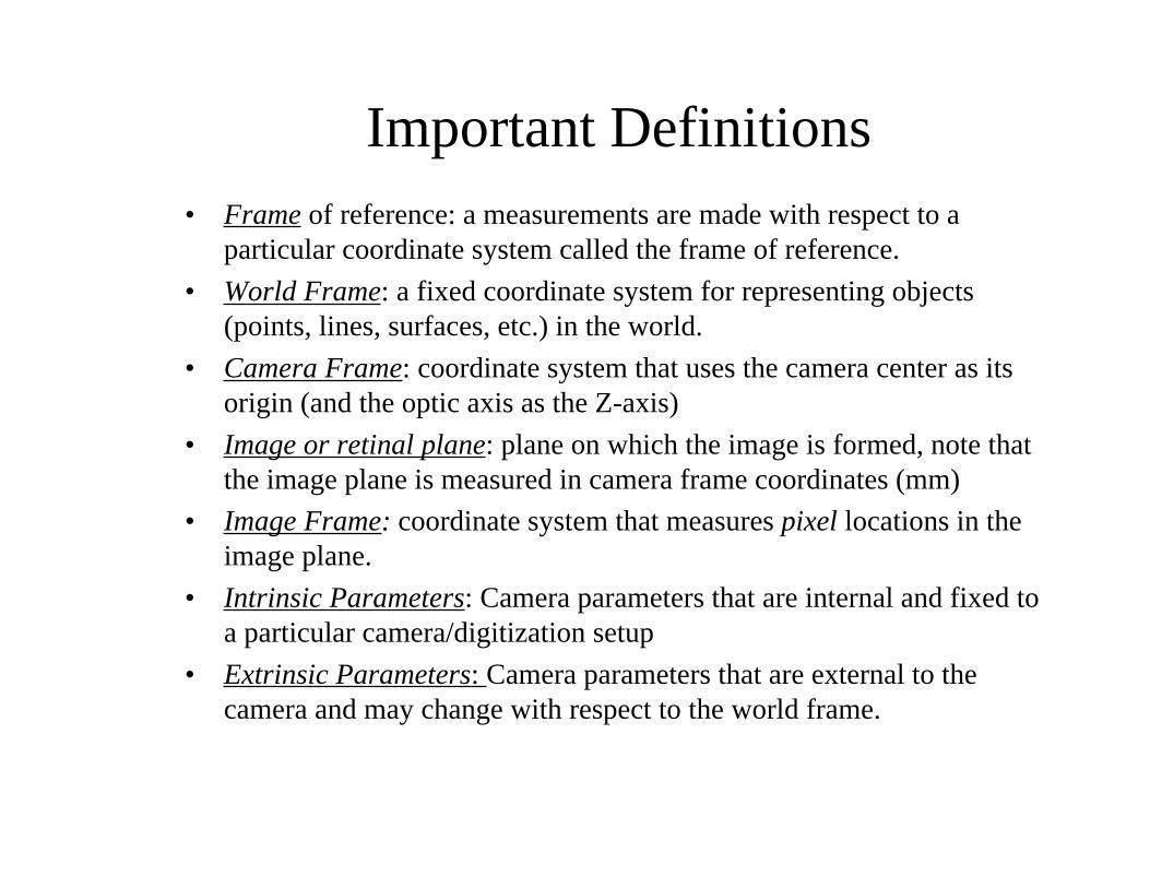
Important Definitions• Frame of reference: a measurements are made with respect to a
particular coordinate system called the frame of reference.
• World Frame: a fixed coordinate system for representing objects(points, lines, surfaces, etc.) in the world.
• Camera Frame: coordinate system that uses the camera center as itsorigin (and the optic axis as the Z-axis)
• Image or retinal plane: plane on which the image is formed, note thatthe image plane is measured in camera frame coordinates (mm)
• Image Frame: coordinate system that measures pixel locations in theimage plane.
• Intrinsic Parameters: Camera parameters that are internal and fixed toa particular camera/digitization setup
• Extrinsic Parameters: Camera parameters that are external to thecamera and may change with respect to the world frame.
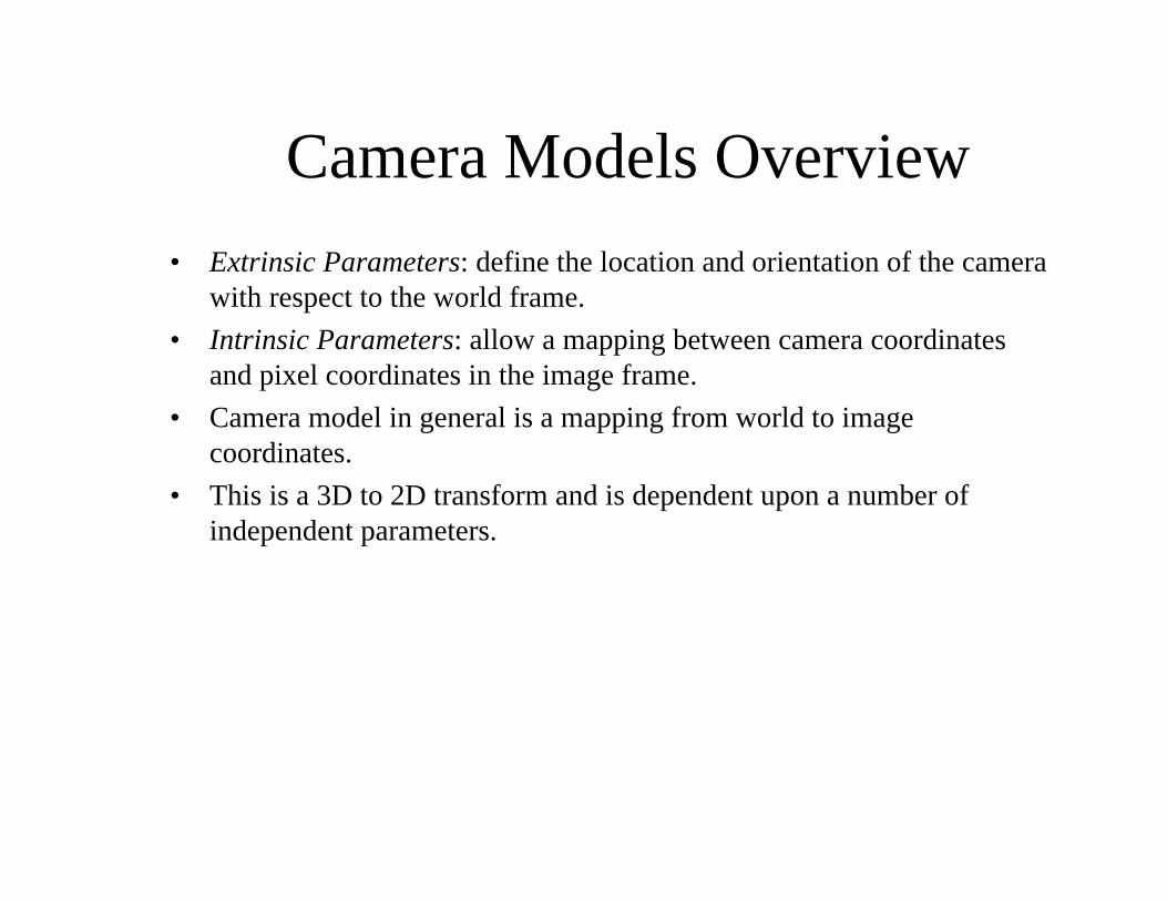
Camera Models Overview
• Extrinsic Parameters: define the location and orientation of the camerawith respect to the world frame.
• Intrinsic Parameters: allow a mapping between camera coordinatesand pixel coordinates in the image frame.
• Camera model in general is a mapping from world to imagecoordinates.
• This is a 3D to 2D transform and is dependent upon a number ofindependent parameters.
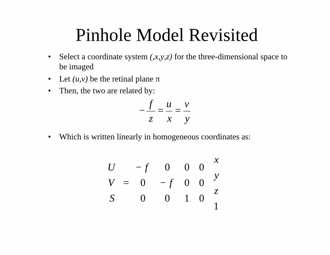
Pinhole Model Revisited• Select a coordinate system (,x,y,z) for the three-dimensional space to
be imaged
• Let (u,v) be the retinal plane π• Then, the two are related by:
y
v
x
u
z
f==−
• Which is written linearly in homogeneous coordinates as:
−
−=
10100
000
000
z
y
x
f
f
S
V
U
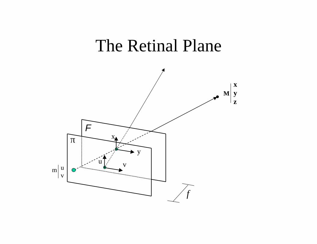
The Retinal Plane
Mxyz
vuy
xπF
m uv
f
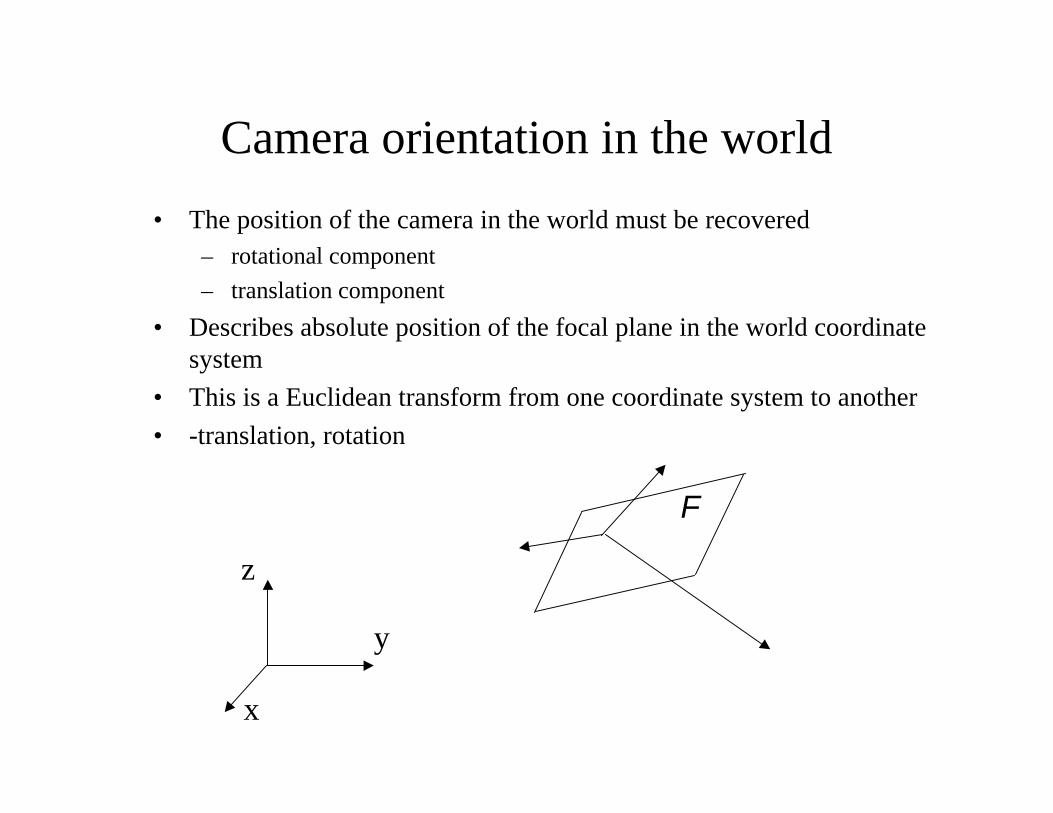
Camera orientation in the world
• The position of the camera in the world must be recovered– rotational component
– translation component
• Describes absolute position of the focal plane in the world coordinatesystem
• This is a Euclidean transform from one coordinate system to another
• -translation, rotation
F
x
y
z
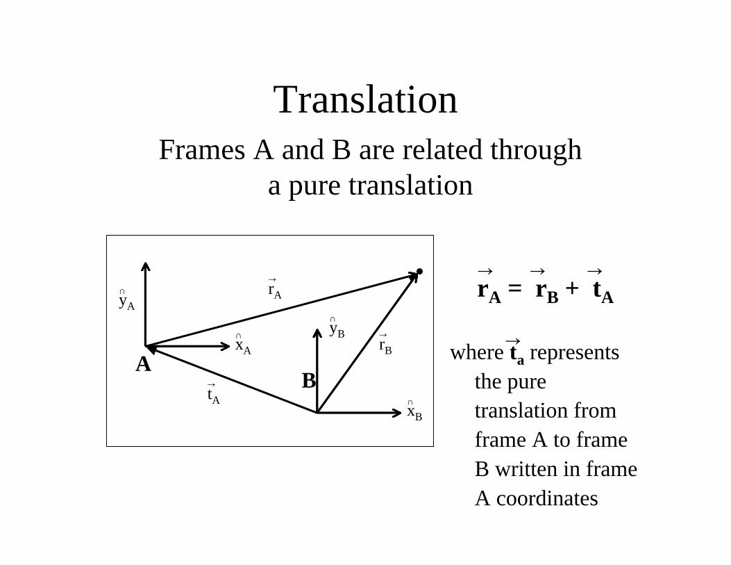
Translation
rA = rB + tA
where ta representsthe puretranslation fromframe A to frameB written in frameA coordinates
AB
∩yA
∩xA
∩yB
∩xB
ÕtA
ÕrA
ÕrB
Frames A and B are related througha pure translation
Õ Õ Õ
Õ
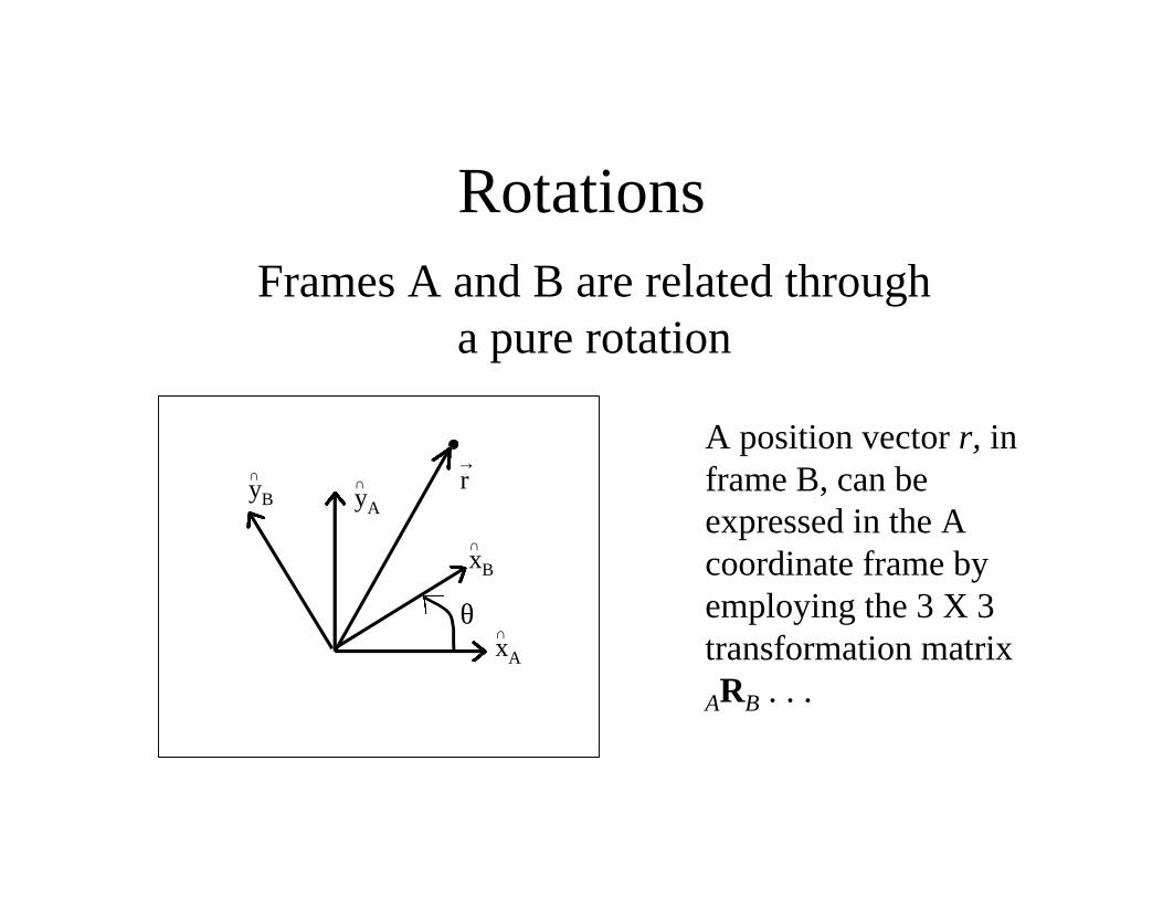
RotationsFrames A and B are related through
a pure rotation
∩yA
∩yB
∩xA
∩xB
Õr
θ
A position vector r, inframe B, can beexpressed in the Acoordinate frame byemploying the 3 X 3transformation matrix
ARB . . .
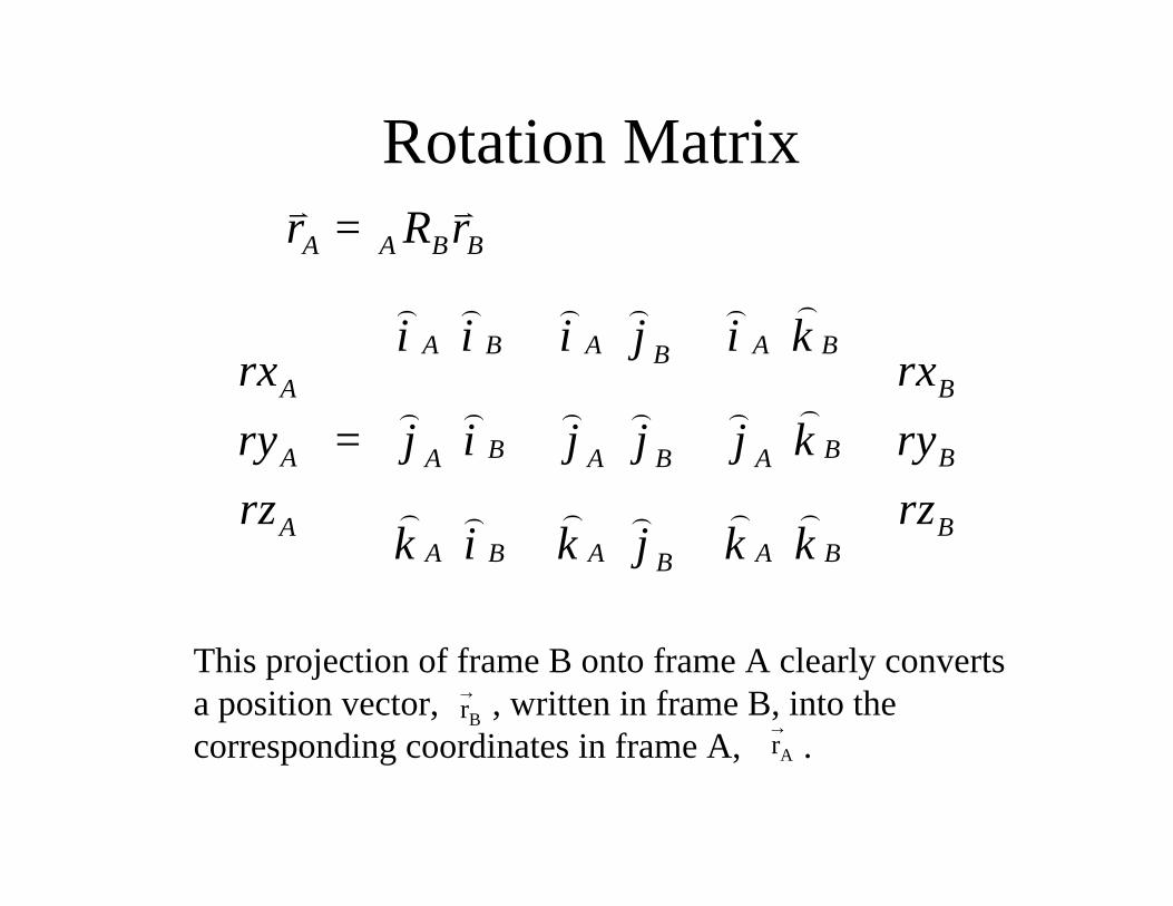
Rotation Matrix
This projection of frame B onto frame A clearly convertsa position vector, , written in frame B, into thecorresponding coordinates in frame A, .
ÕrB
ÕrA
A A B B
A B A A BBA B
B BA BA A B A
A BA B A A BB
r R r
i i i j i krx rx
ry j i j j j k ry
rz rzk i k j k k
=
⋅ ⋅ ⋅ = ⋅ ⋅ ⋅ ⋅ ⋅ ⋅
v v
)) ) ) ) )
)) ) ) ) )
) ) ) )) )
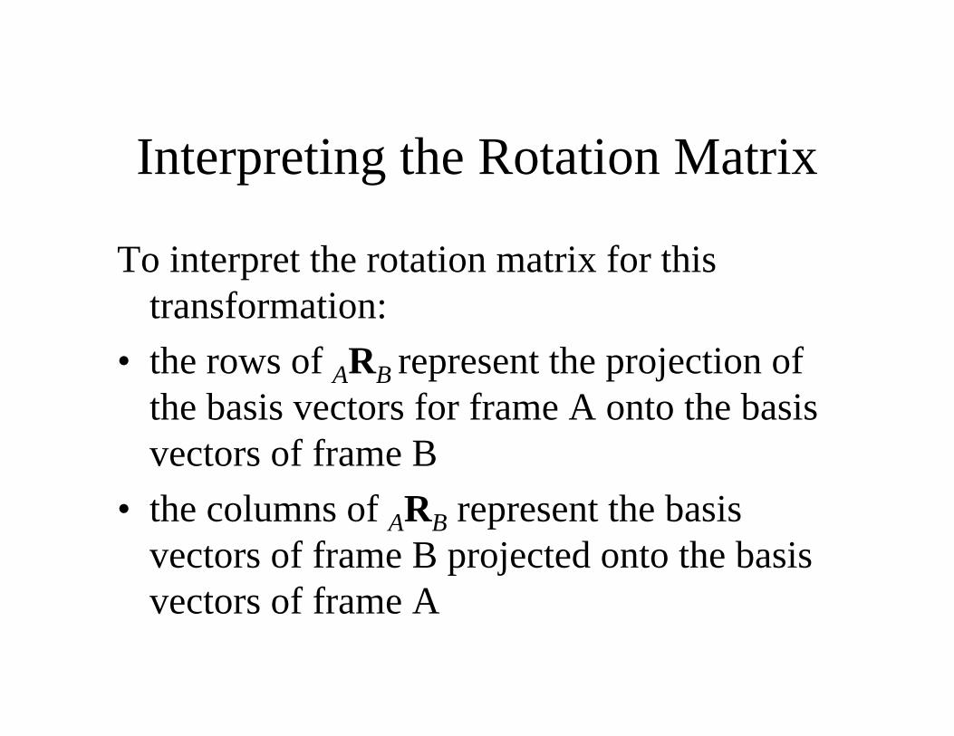
Interpreting the Rotation Matrix
To interpret the rotation matrix for thistransformation:
• the rows of ARB represent the projection ofthe basis vectors for frame A onto the basisvectors of frame B
• the columns of ARB represent the basisvectors of frame B projected onto the basisvectors of frame A
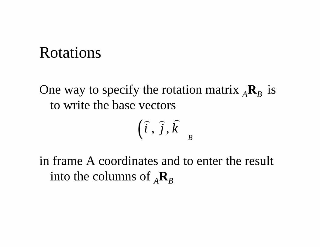
Rotations
One way to specify the rotation matrix ARB isto write the base vectors
in frame A coordinates and to enter the resultinto the columns of ARB
( ), ,B
i j k)) )
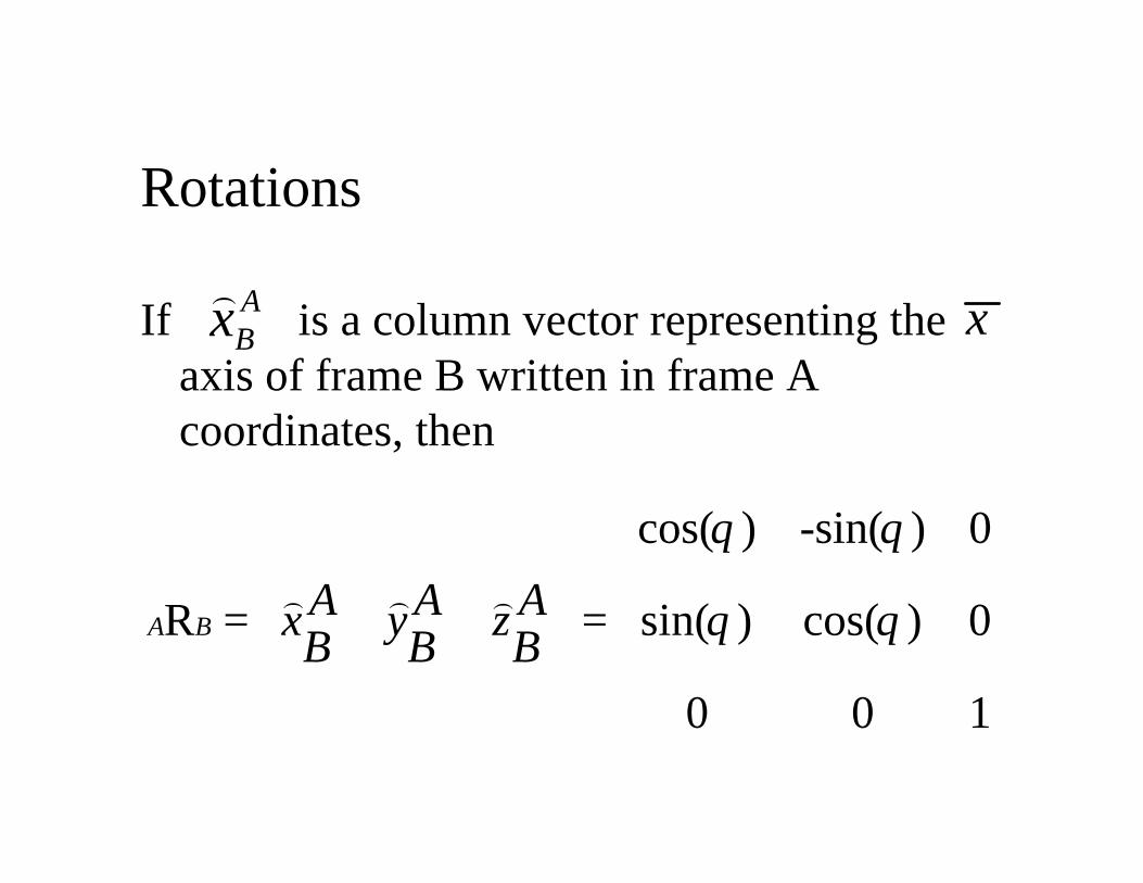
If is a column vector representing theaxis of frame B written in frame Acoordinates, then
ABx
)x
cos( ) -sin( ) 0
R sin( ) cos( ) 0
0 0 1
A BA A Ax y zB B B
θ θ
θ θ
= =
) ) )
Rotations
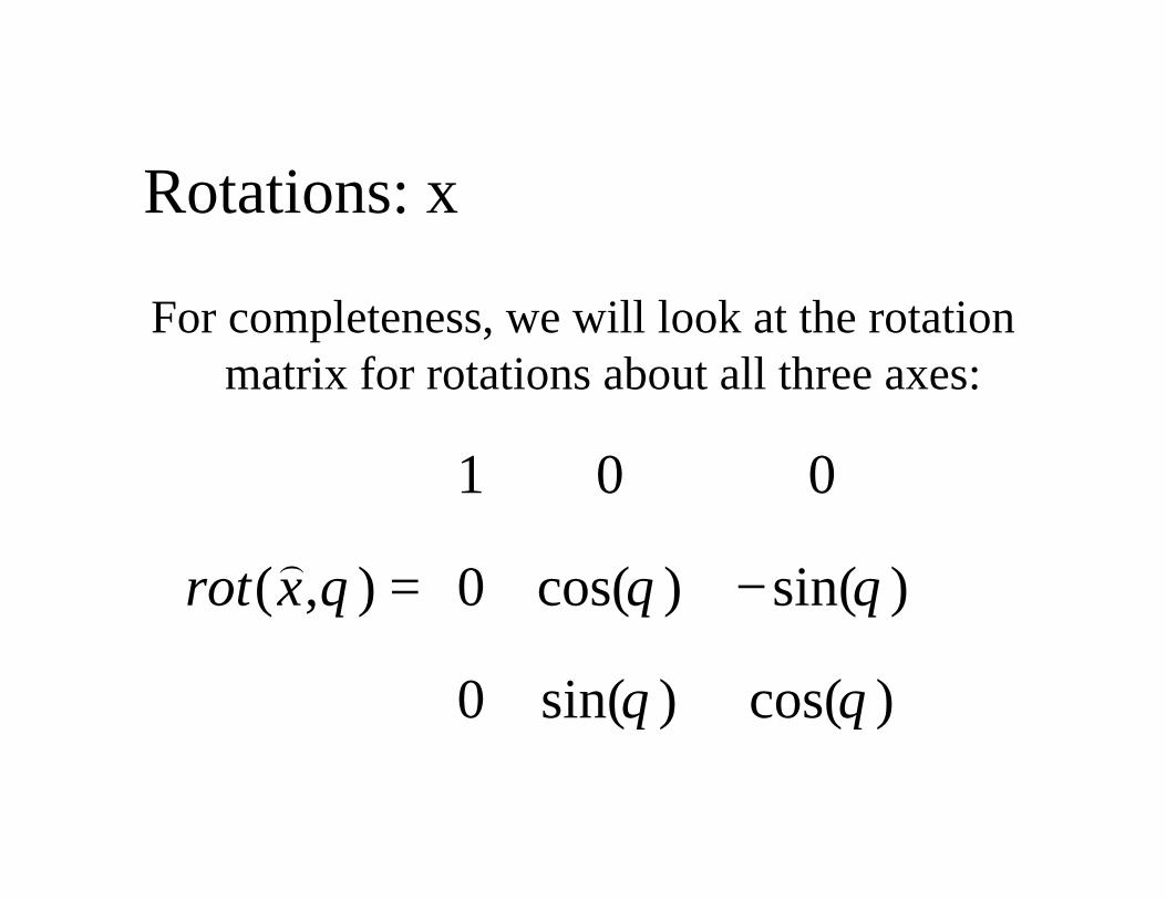
Rotations: x
For completeness, we will look at the rotationmatrix for rotations about all three axes:
1 0 0
( , ) 0 cos( ) sin( )
0 sin( ) cos( )
rot x θ θ θ
θ θ
= −
)
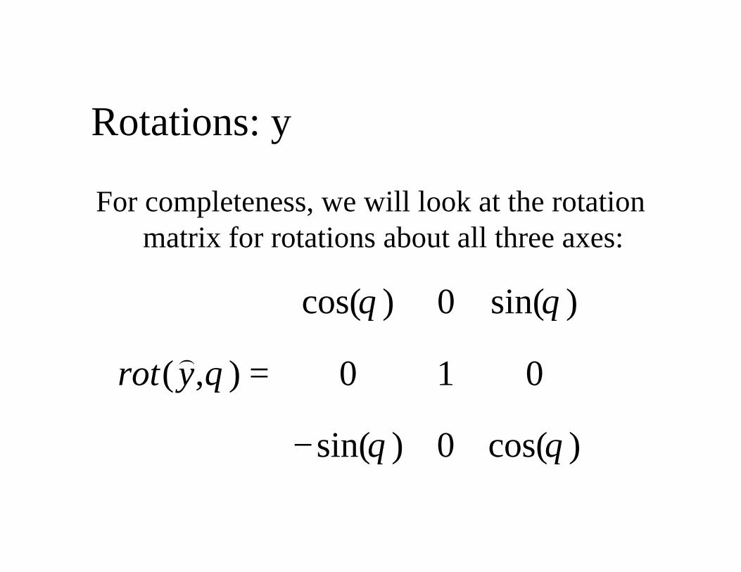
Rotations: y
For completeness, we will look at the rotationmatrix for rotations about all three axes:
cos( ) 0 sin( )
( , ) 0 1 0
sin( ) 0 cos( )
rot y
θ θ
θ
θ θ
= −
)
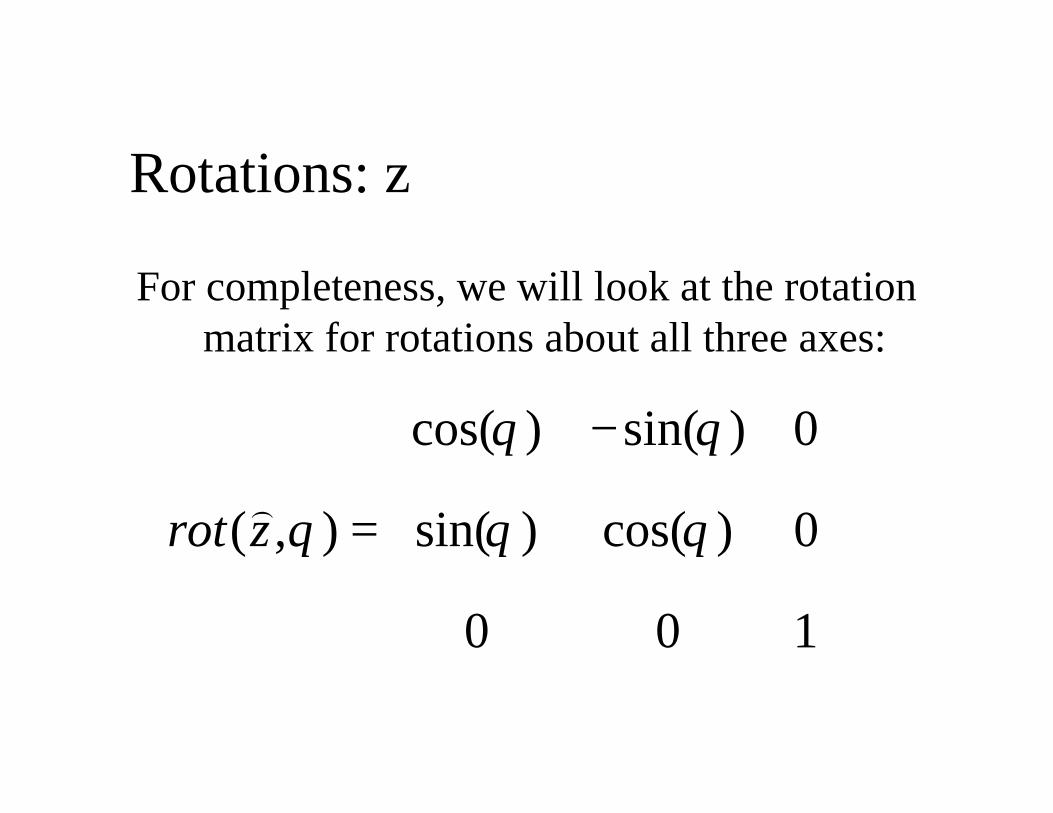
Rotations: z
For completeness, we will look at the rotationmatrix for rotations about all three axes:
cos( ) sin( ) 0
( , ) sin( ) cos( ) 0
0 0 1
rot z
θ θ
θ θ θ
− =
)
Extrinsic Parameters
• Recall the fundamental equations of perspective projection– assumed the orientation of the camera and world frame known
– this is actually a difficult problem known as extrinsic pose problem
– using only image information recover the relative position andorientation of the camera and world frames
• This transformation is typically defined by:– 3-D translation vector T=[x,y,z]T
• defines relative positions of each frame
– 3x3 rotation matrix, R• rotates corresponding axes of each frame into each other
• R is orthogonal: (RTR = RRT =I)
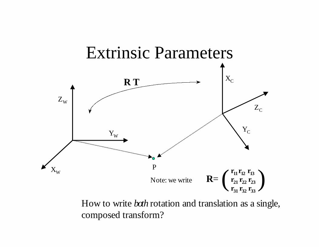
Extrinsic Parameters
R T
PXW
YW
ZWZC
XC
YC
Note: we write R=r11 r12 r13r21 r22 r23r31 r32 r33
( )How to write both rotation and translation as a single,composed transform?
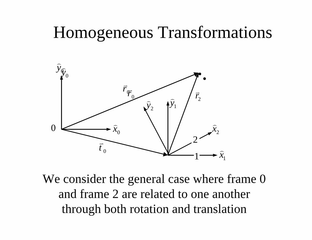
We consider the general case where frame 0and frame 2 are related to one anotherthrough both rotation and translation
0y)
0x)
0rv
0tv
1x)
2x)
1y)
2y) 2r
v
1
20
Homogeneous Transformations
0y)
0rv
Homogeneous Transformations
The homogeneous transform is amechanism for expressing this form of
compound transformation
0y)
0x)
0rv
0tv
1x)
2x)
1y)
2y) 2r
v
1
20
Homogeneous Transforms
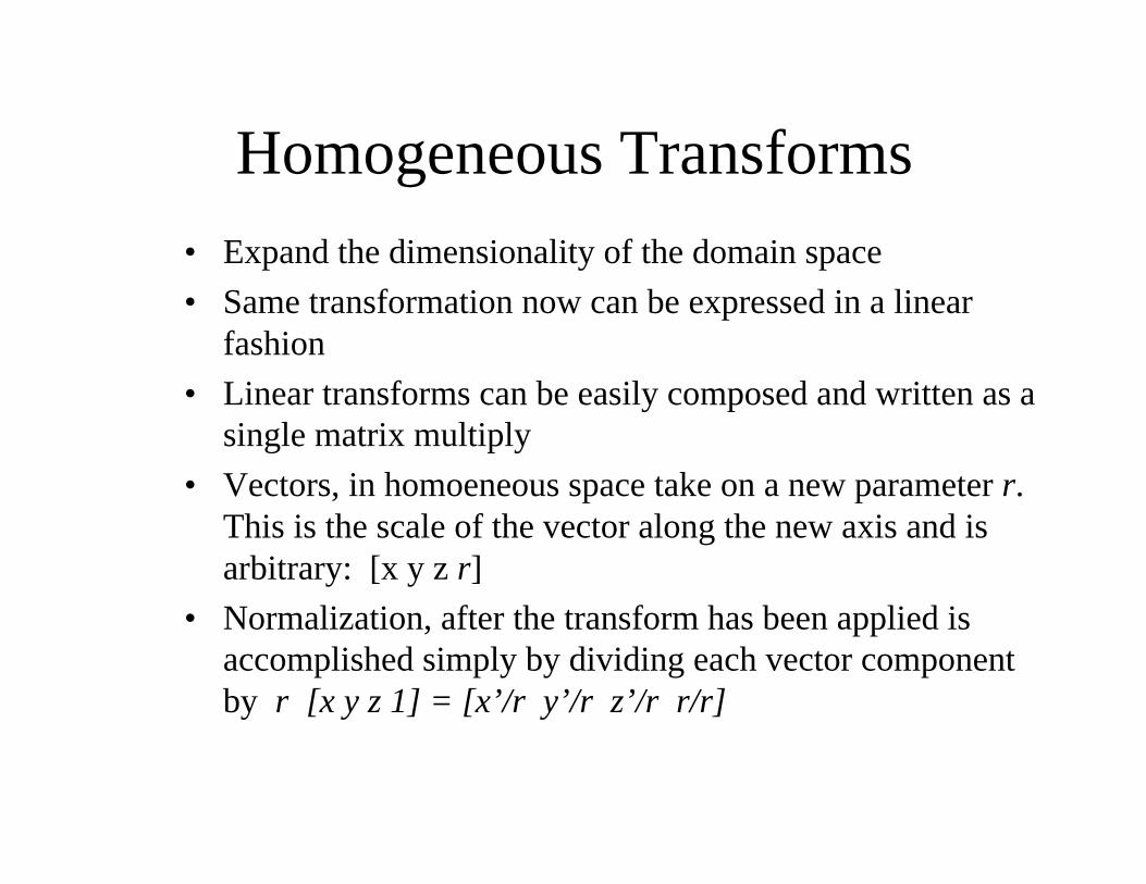
• Expand the dimensionality of the domain space
• Same transformation now can be expressed in a linearfashion
• Linear transforms can be easily composed and written as asingle matrix multiply
• Vectors, in homoeneous space take on a new parameter r.This is the scale of the vector along the new axis and isarbitrary: [x y z r]
• Normalization, after the transform has been applied isaccomplished simply by dividing each vector componentby r [x y z 1] = [x’/r y’/r z’/r r/r]
Homogeneous Transformations
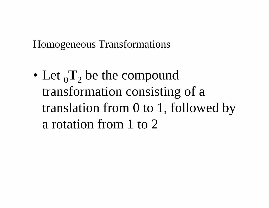
• Let 0T2 be the compoundtransformation consisting of atranslation from 0 to 1, followed bya rotation from 1 to 2
Homogeneous Transformations
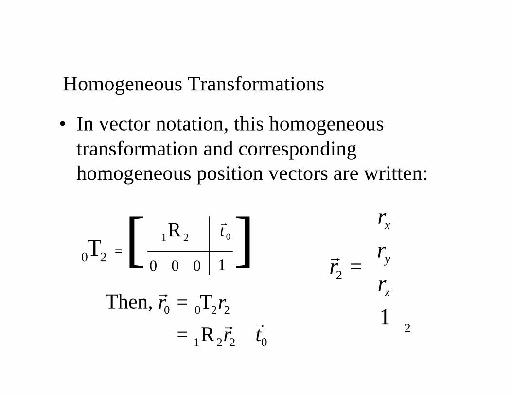
• In vector notation, this homogeneoustransformation and correspondinghomogeneous position vectors are written:
0 2T =1 2R
0 0 0
0tr
1[ ]
2
21
x
y
z
r
rr
r
=
r
0 0 2 2
1 2 2 0
T
R
r r
r t
=
= +
r
rrThen,
Composing Transformations
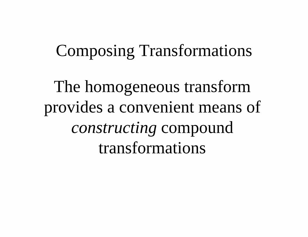
The homogeneous transformprovides a convenient means of
constructing compoundtransformations
Composing Transformations
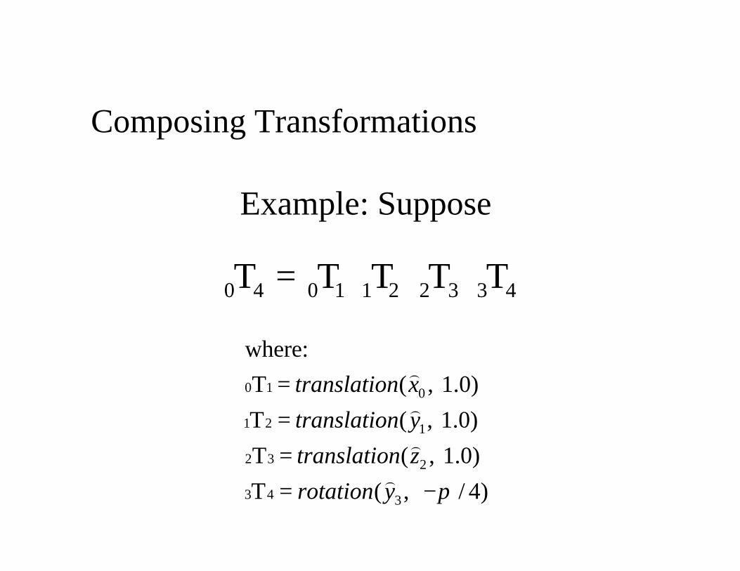
Example: Suppose
0 1 0
1 2 1
2 3 2
3 4 3
where:
T ( , 1.0)
T ( , 1.0)
T ( , 1.0)
T ( , / 4)
translation x
translation y
translation z
rotation y π
==== −
)
)
)
)
0 4 0 1 1 2 2 3 3 4T T T T T=
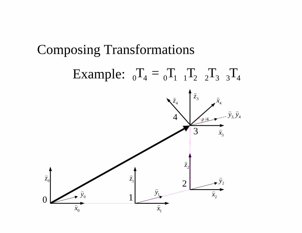
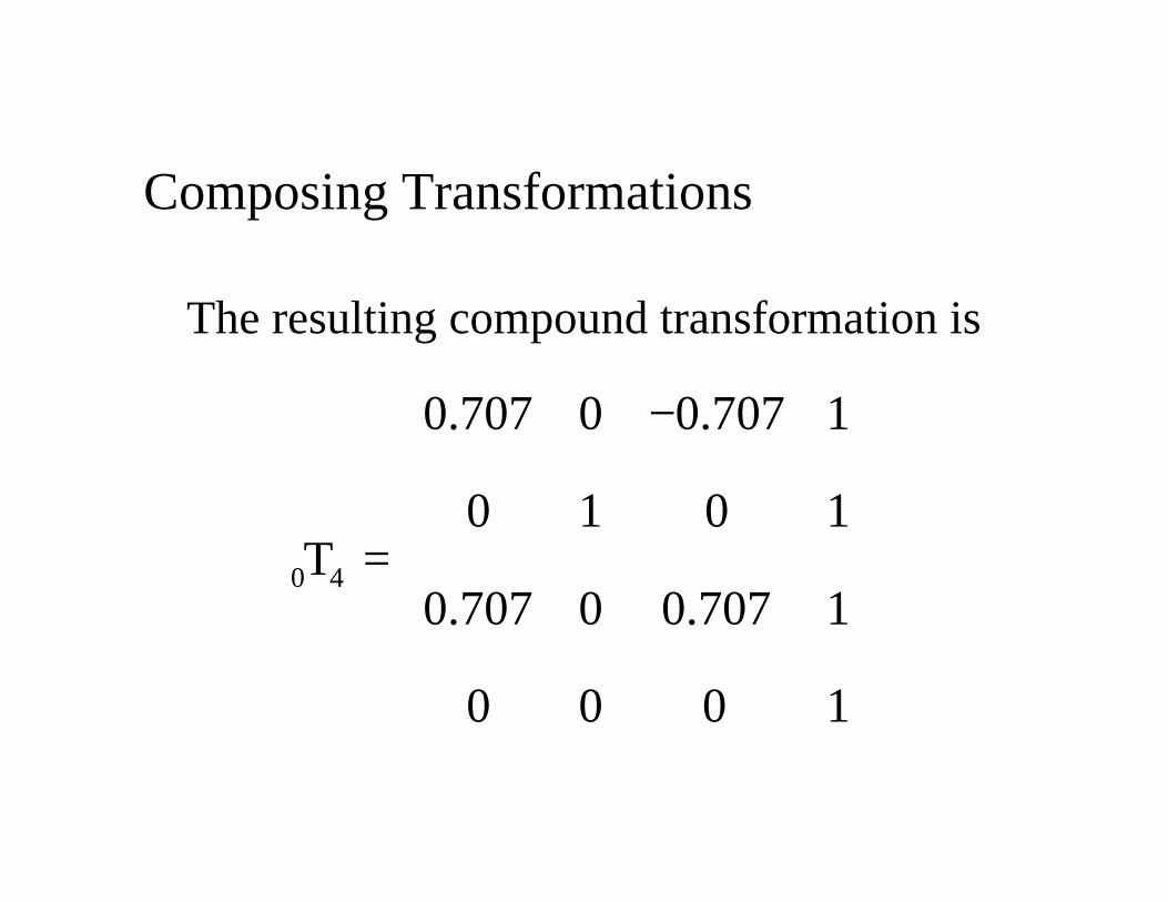
Composing Transformations
Example: 0 4 0 1 1 2 2 3 3 4T T T T T=
0x)
0 y)
0z)
1x)
1y)
1z)
2x)
2y)
2z)
3x)
3, 4y y) )
3z)
4x)
4z)
4
3
2
10
/4π
The resulting compound transformation is
Composing Transformations
0 4
0.707 0 0.707 1
0 1 0 1T
0.707 0 0.707 1
0 0 0 1
− =
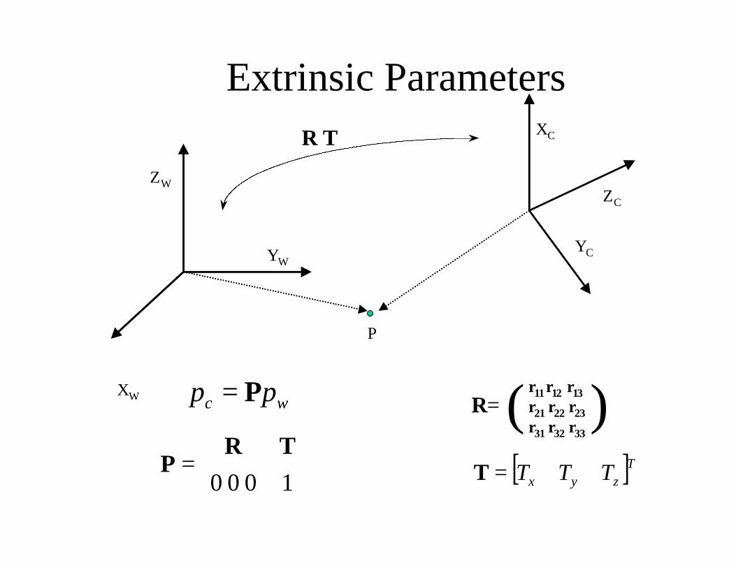
Extrinsic ParametersR T
P
XW
YW
ZWZC
XC
YC
R=r11 r12 r13r21 r22 r23r31 r32 r33
( )wc pp P=
=
1000
TRP [ ]Tzyx TTT=T
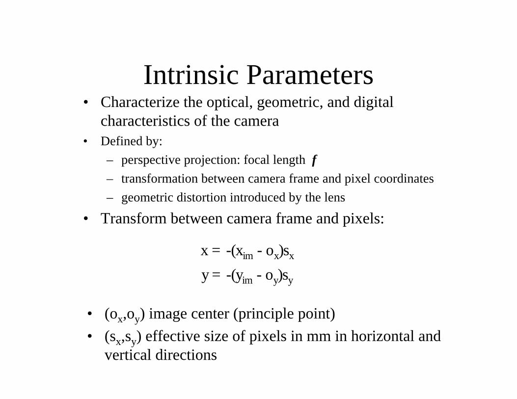
Intrinsic Parameters• Characterize the optical, geometric, and digital
characteristics of the camera• Defined by:
– perspective projection: focal length f
– transformation between camera frame and pixel coordinates
– geometric distortion introduced by the lens
• Transform between camera frame and pixels:
x = -(xim - ox)sx
y = -(yim - oy)sy
• (ox,oy) image center (principle point)
• (sx,sy) effective size of pixels in mm in horizontal andvertical directions
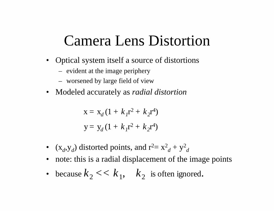
Camera Lens Distortion• Optical system itself a source of distortions
– evident at the image periphery
– worsened by large field of view
• Modeled accurately as radial distortion
x = xd (1 + k1r2 + k2r4)
y = yd (1 + k1r2 + k2r4)
• (xd,yd) distorted points, and r2= x2d + y2
d
• note: this is a radial displacement of the image points
• because k2 << k1, k2 is often ignored.
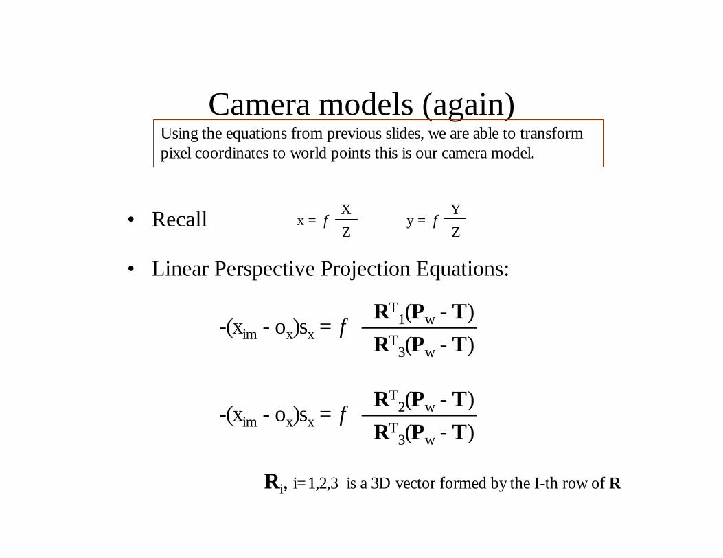
Camera models (again)
• Recall
Using the equations from previous slides, we are able to transformpixel coordinates to world points this is our camera model.
-(xim - ox)sx = fRT
1(Pw - T)
RT3(Pw - T)
-(xim - ox)sx = fRT
2(Pw - T)
RT3(Pw - T)
Ri, i=1,2,3 is a 3D vector formed by the I-th row of R
x = f y = f X
Z
Y
Z
• Linear Perspective Projection Equations:
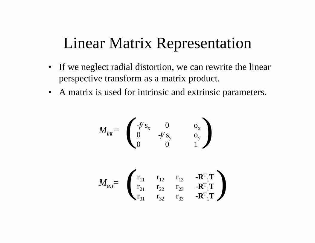
Linear Matrix Representation• If we neglect radial distortion, we can rewrite the linear
perspective transform as a matrix product.
• A matrix is used for intrinsic and extrinsic parameters.
Mext=
Mint = -f/sx 0 ox
0 -f/sy oy
0 0 1( )
r11 r12 r13 -RT1T
r21 r22 r23 -RT1T
r31 r32 r33 -RT1T
( )
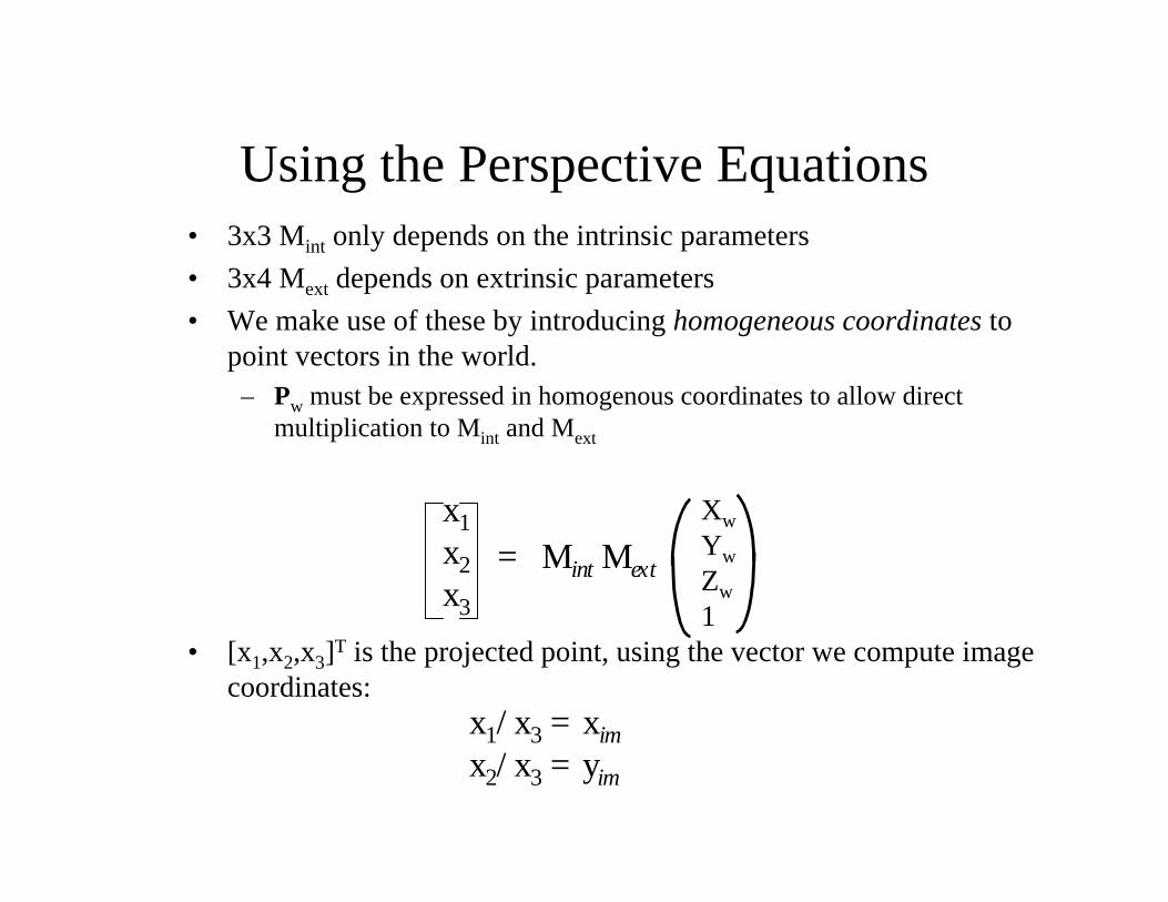
Using the Perspective Equations• 3x3 Mint only depends on the intrinsic parameters
• 3x4 Mext depends on extrinsic parameters
• We make use of these by introducing homogeneous coordinates topoint vectors in the world.
– Pw must be expressed in homogenous coordinates to allow directmultiplication to Mint and Mext
x1
x2x3
= Mint Mext
Xw
Yw
Zw
1• [x1,x2,x3]T is the projected point, using the vector we compute image
coordinates:x1/x3 = xim
x2/x3 = yim
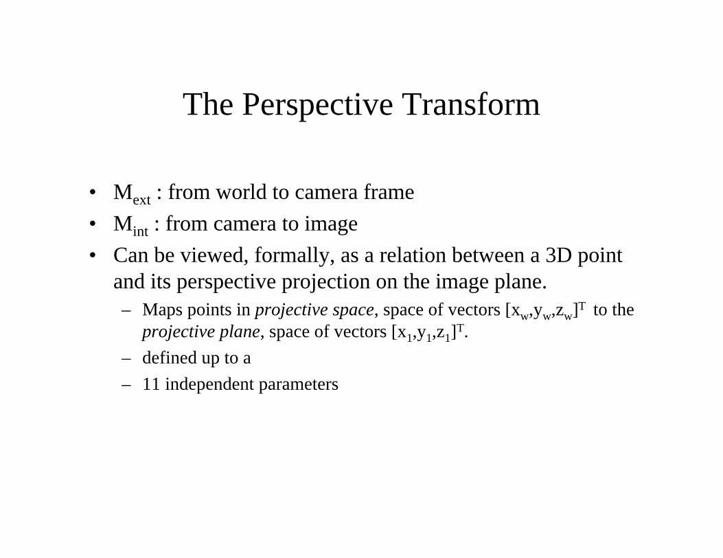
The Perspective Transform
• Mext : from world to camera frame
• Mint : from camera to image
• Can be viewed, formally, as a relation between a 3D pointand its perspective projection on the image plane.– Maps points in projective space, space of vectors [xw,yw,zw]T to the
projective plane, space of vectors [x1,y1,z1]T.
– defined up to a
– 11 independent parameters
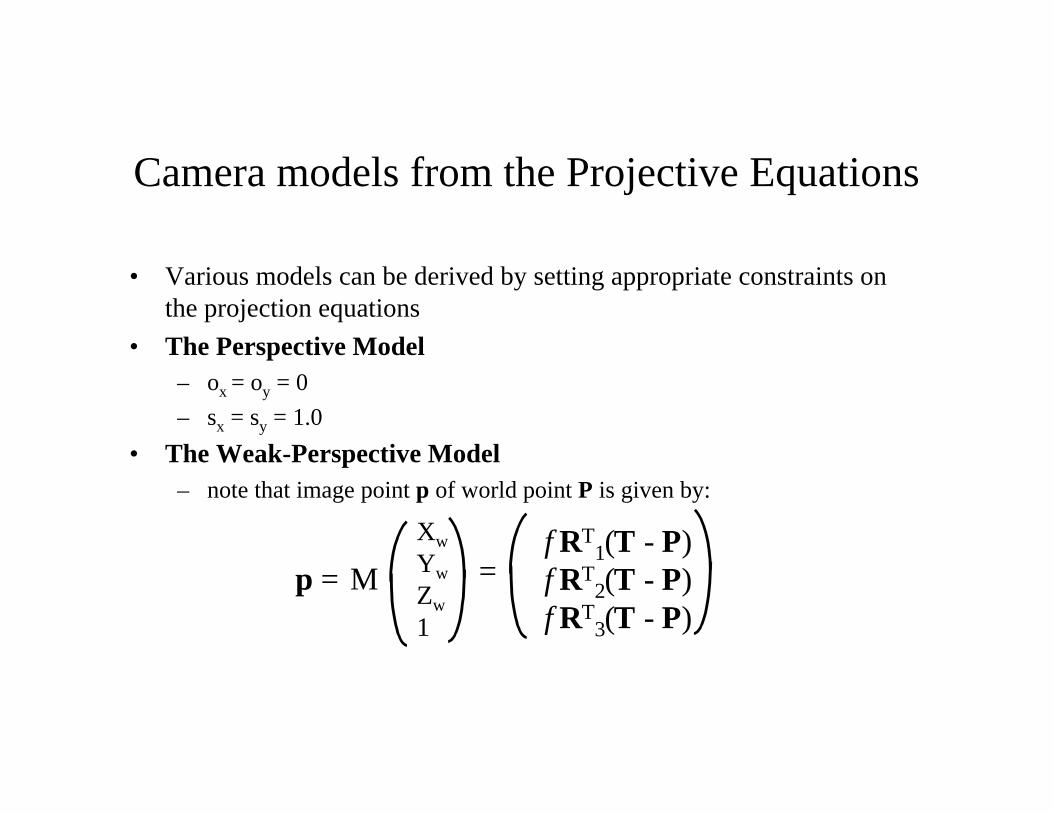
Camera models from the Projective Equations
• Various models can be derived by setting appropriate constraints onthe projection equations
• The Perspective Model– ox = oy = 0
– sx = sy = 1.0
• The Weak-Perspective Model– note that image point p of world point P is given by:
p = M
Xw
Yw
Zw
1
=f RT
1(T - P)f RT
2(T - P)f RT
3(T - P)
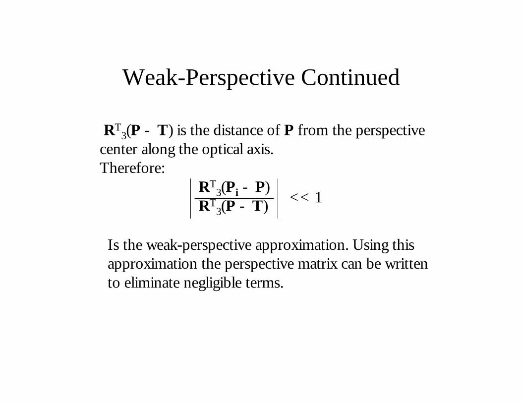
Weak-Perspective Continued
RT3(P - T) is the distance of P from the perspective
center along the optical axis.Therefore:
RT3(Pi - P)
RT3(P - T) << 1
Is the weak-perspective approximation. Using this approximation the perspective matrix can be writtento eliminate negligible terms.