Embed Size (px)
Citation preview
1
1
Calibration Plan for the Ocean Color Instrument (OCI) Engineering Test Unit
Gerhard Meister, PACE Instrument Scientist, NASA Code 616
Coauthors:William B. Cook, NASA Code 551Joseph J. Knuble, NASA Code 592Eric T. Gorman, NASA Code 592
P. Jeremy Werdell, NASA Code 616
SPIE Remote Sensing 2019Sensors, Systems, and Next-Generation Satellites XXIII
Strasbourg, France, September 12, 20191
2
OCI calibration overview
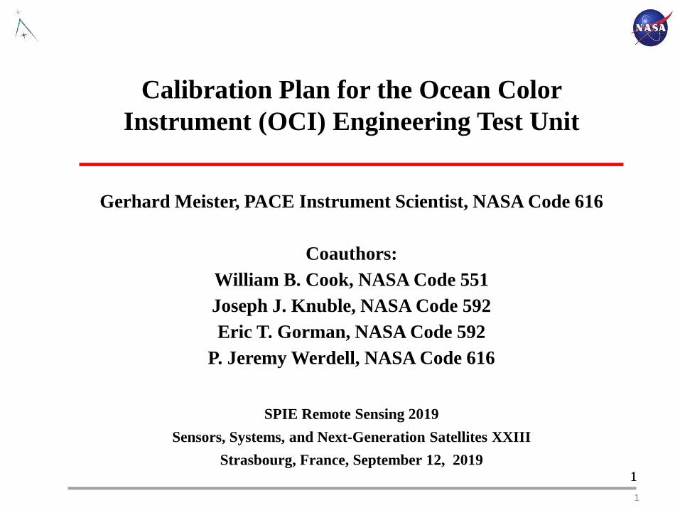
• The basic product measured by OCI is the top-of atmosphere (TOA) radiance at different wavelengths
• Three types of calibration/characterization are necessary for ocean color processing:- Prelaunch calibration/characterization (absolute/spectral calibration and image artifacts)- On-orbit calibration (solar diffuser and lunar measurements)- Vicarious calibration (in-situ measurements of water-leaving radiance)
PACE Error Budget Peer Review; June 2017
3
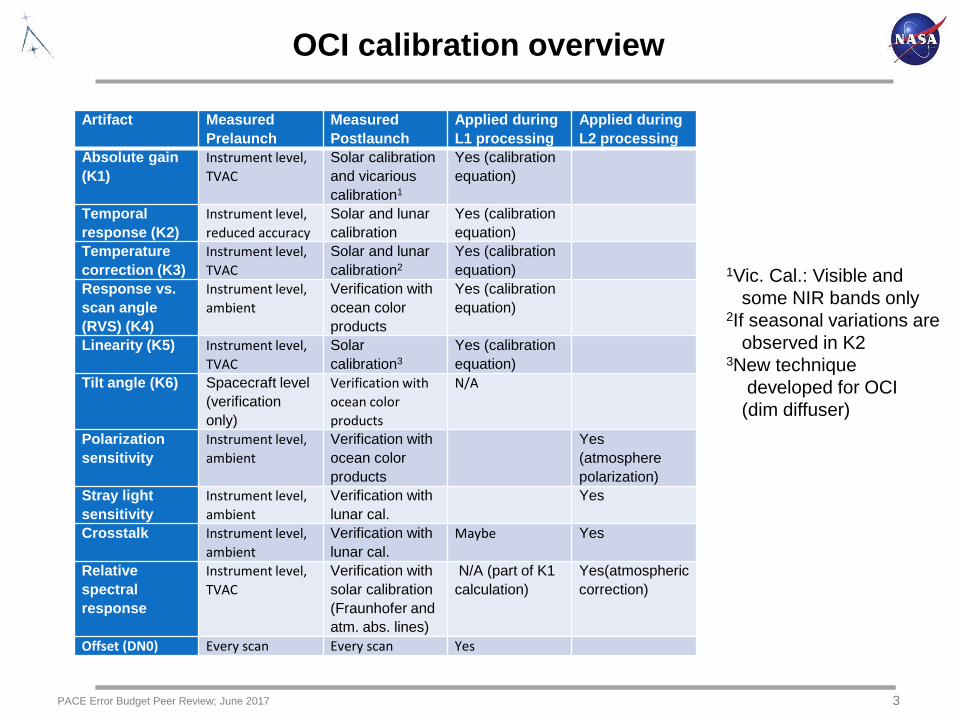
OCI calibration overview
PACE Error Budget Peer Review; June 2017
Artifact Measured Prelaunch
Measured Postlaunch
Applied during L1 processing
Applied during L2 processing
Absolute gain (K1)
Instrument level, TVAC
Solar calibration and vicarious calibration1
Yes (calibration equation)
Temporal response (K2)
Instrument level, reduced accuracy
Solar and lunar calibration
Yes (calibration equation)
Temperature correction (K3)
Instrument level, TVAC
Solar and lunar calibration2
Yes (calibration equation)
Response vs. scan angle (RVS) (K4)
Instrument level, ambient
Verification with ocean color products
Yes (calibration equation)
Linearity (K5) Instrument level, TVAC
Solar calibration3
Yes (calibration equation)
Tilt angle (K6) Spacecraft level (verification only)
Verification with ocean color products
N/A
Polarization sensitivity
Instrument level, ambient
Verification with ocean color products
Yes (atmosphere polarization)
Stray light sensitivity
Instrument level, ambient
Verification with lunar cal.
Yes
Crosstalk Instrument level, ambient
Verification with lunar cal.
Maybe Yes
Relative spectral response
Instrument level, TVAC
Verification with solar calibration (Fraunhofer and atm. abs. lines)
N/A (part of K1 calculation)
Yes(atmospheric correction)
Offset (DN0) Every scan Every scan Yes
1Vic. Cal.: Visible and some NIR bands only
2If seasonal variations are observed in K2
3New technique developed for OCI
(dim diffuser)
4
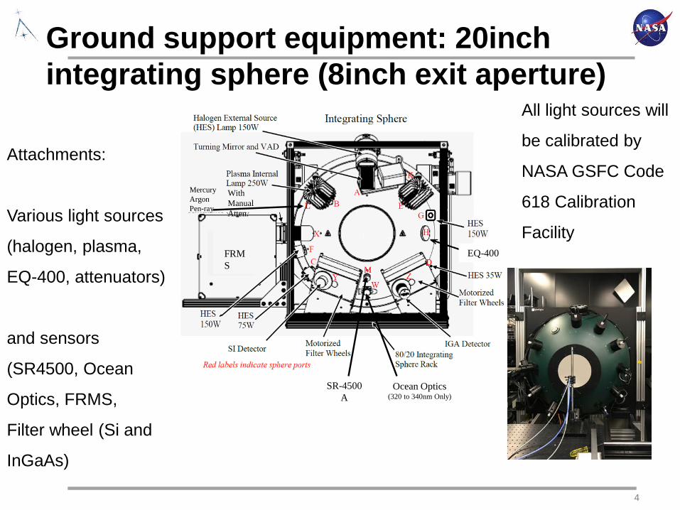
SR-4500 A
FRMS
With Manual Atten.
EQ-400
Ocean Optics(320 to 340nm Only)
Mercury Argon Pen-ray
Ground support equipment: 20inch integrating sphere (8inch exit aperture)
Attachments:
Various light sources
(halogen, plasma,
EQ-400, attenuators)
and sensors
(SR4500, Ocean
Optics, FRMS,
Filter wheel (Si and
InGaAs)
All light sources will
be calibrated by
NASA GSFC Code
618 Calibration
Facility
5
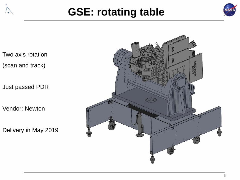
GSE: rotating table
Two axis rotation
(scan and track)
Just passed PDR
Vendor: Newton
Delivery in May 2019
6
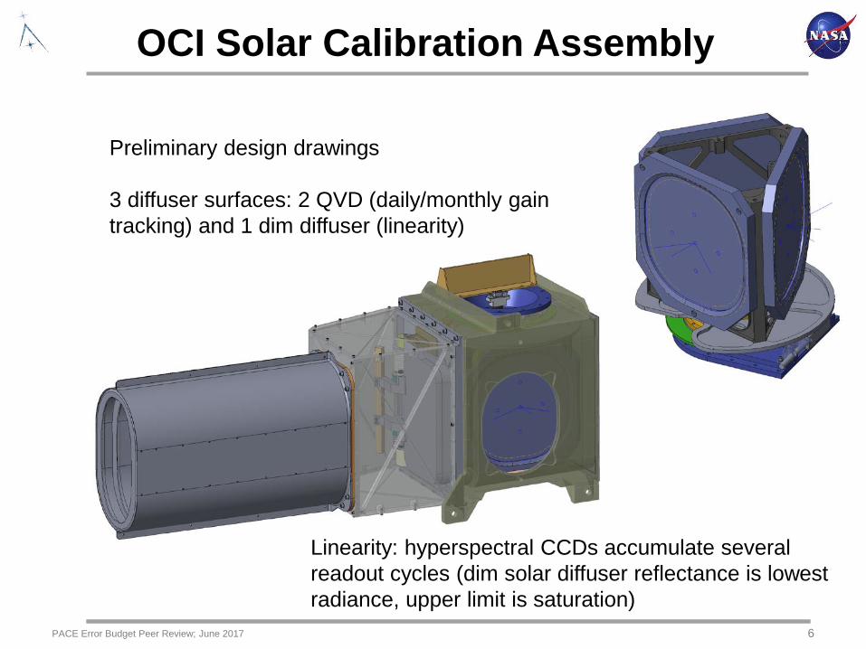
OCI Solar Calibration Assembly
PACE Error Budget Peer Review; June 2017
Preliminary design drawings
3 diffuser surfaces: 2 QVD (daily/monthly gain tracking) and 1 dim diffuser (linearity)
Linearity: hyperspectral CCDs accumulate several readout cycles (dim solar diffuser reflectance is lowest radiance, upper limit is saturation)
7
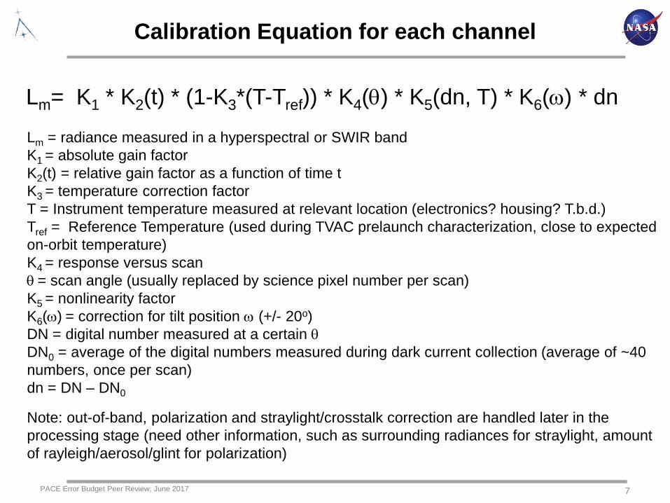
Calibration Equation for each channel
PACE Error Budget Peer Review; June 2017
Lm= K1 * K2(t) * (1-K3*(T-Tref)) * K4(θ) * K5(dn, T) * K6(ω) * dn
Lm = radiance measured in a hyperspectral or SWIR bandK1 = absolute gain factor K2(t) = relative gain factor as a function of time t K3 = temperature correction factorT = Instrument temperature measured at relevant location (electronics? housing? T.b.d.)Tref = Reference Temperature (used during TVAC prelaunch characterization, close to expected on-orbit temperature)K4 = response versus scan θ = scan angle (usually replaced by science pixel number per scan)K5 = nonlinearity factorK6(ω) = correction for tilt position ω (+/- 20o)DN = digital number measured at a certain θDN0 = average of the digital numbers measured during dark current collection (average of ~40 numbers, once per scan) dn = DN – DN0
Note: out-of-band, polarization and straylight/crosstalk correction are handled later in the processing stage (need other information, such as surrounding radiances for straylight, amount of rayleigh/aerosol/glint for polarization)

8
Absolute calibration K1: 3 uncertainties
•K1 is a single number per band and mirror side, with units
[radiance/dn]
•Prelaunch: GLAMR will provide absolute calibration, better
than 0.5% accuracy
•Initial on-orbit calibration: solar diffuser will provide absolute
calibration with <2% uncertainty
•Vicarious calibration will provide absolute calibration for most
bands with 0.1% uncertainty after sufficient number of
matchups have been acquired
PACE Error Budget Peer Review; June 2017
Lm= K1 * K2(t) * (1-K3*(T-Tref)) * K4(θ) * K5(dn, T) * K6(ω) * dn
9
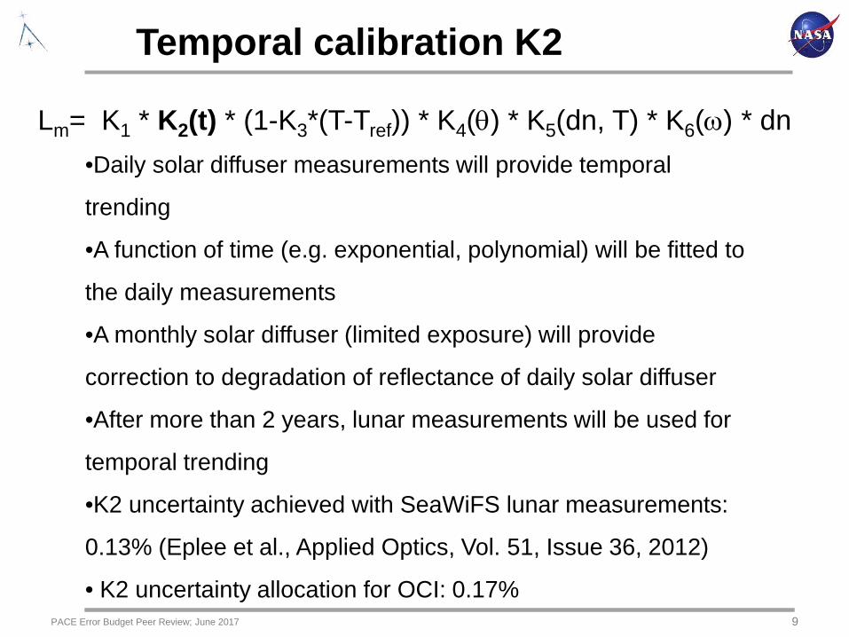
Temporal calibration K2
•Daily solar diffuser measurements will provide temporal
trending
•A function of time (e.g. exponential, polynomial) will be fitted to
the daily measurements
•A monthly solar diffuser (limited exposure) will provide
correction to degradation of reflectance of daily solar diffuser
•After more than 2 years, lunar measurements will be used for
temporal trending
•K2 uncertainty achieved with SeaWiFS lunar measurements:
0.13% (Eplee et al., Applied Optics, Vol. 51, Issue 36, 2012)
• K2 uncertainty allocation for OCI: 0.17%PACE Error Budget Peer Review; June 2017
Lm= K1 * K2(t) * (1-K3*(T-Tref)) * K4(θ) * K5(dn, T) * K6(ω) * dn
10
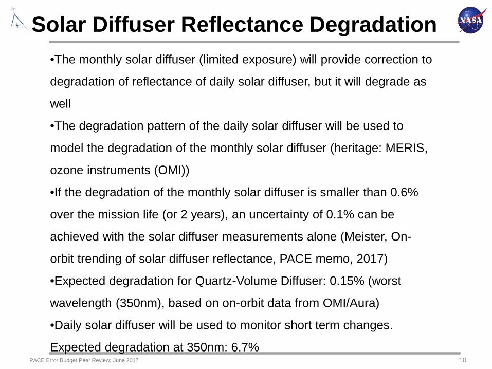
Solar Diffuser Reflectance Degradation •The monthly solar diffuser (limited exposure) will provide correction to
degradation of reflectance of daily solar diffuser, but it will degrade as
well
•The degradation pattern of the daily solar diffuser will be used to
model the degradation of the monthly solar diffuser (heritage: MERIS,
ozone instruments (OMI))
•If the degradation of the monthly solar diffuser is smaller than 0.6%
over the mission life (or 2 years), an uncertainty of 0.1% can be
achieved with the solar diffuser measurements alone (Meister, On-
orbit trending of solar diffuser reflectance, PACE memo, 2017)
•Expected degradation for Quartz-Volume Diffuser: 0.15% (worst
wavelength (350nm), based on on-orbit data from OMI/Aura)
•Daily solar diffuser will be used to monitor short term changes.
Expected degradation at 350nm: 6.7%PACE Error Budget Peer Review; June 2017

11PACE Error Budget Peer Review; June 2017
Lunar calibration background:• Stable exo-atmospheric radiometric source with light levels comparable to
TOA Earth observations.• Moon used as reference by SeaWiFS, MODIS (2), and VIIRS.• Observations require geometric correction for instrument-Moon and Sun-
Moon distances, phase angle, libration angles.• Frequency of observation: Twice per month (before and after full phase)
over a limited range of phase angles (7deg +/- 0.5deg).• Limitations:
• Will require image oversampling correction.• Inherent scatter in observations (1-2%).• Multi-year time series required to identify radiometric trends.
Geometric corrections: • Complication: Heterogeneous albedo distribution over the lunar surface• Corrections provided by USGS ROLO Lunar Photometric Model• ROLO Model used as reference by most Earth-observing instruments
Lunar Calibration

12
Summary
• OCI will start a rigorous calibration program in June
2019 with the ETU (Flight Unit: summer 2020)
• Goal is to minimize uncertainties due to image artifacts
described here in order to achieve overall radiometric
uncertainty of 0.5% (excluding absolute calibration)
• OCI will provide excellent temporal stability over
mission life time (2 solar diffusers, lunar
measurements twice a month)
• Linearity will be verified on-orbit with dim solar diffuser
(new approach)PACE Error Budget Peer Review; June 2017