Embed Size (px)
Citation preview
cc:
LW ::c t-
� :::z:: <
en � :::z:: LW :IE ..... cc: :::::::> en ice ..... :IE
CALIBRATION OF EQUIPMENT IN THE LOW AND
MEDIUM RADIO-FREQUENCY RANGES, IN SMALL
STEPS OF FR EQUENCY
IN TH IS ISSUE
HOUCTIT IT GRlEFS TO ;rENERAL R 010 6
MAI TEN\ 'CE ' ITH THE TROB T 8
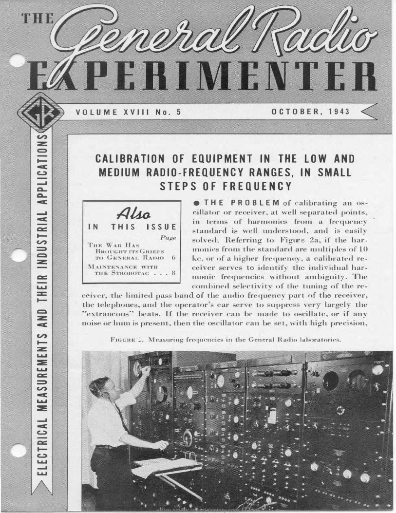
e T H E P R 0 B L E M I alibrating an cillator or re ei er, at weU eparated points, in terms of harmonics from a frequcnc
tandard i well un ·er tood, and i a i L olved. R ferring to Figur 2a, i( the har-
1nonics from the standard are muhiples of 10 k , or of a higher freq uenc r, a calibrated re-
1ver r e t id n ti{ th indi idual har-m nic frequencie without ambiguit . The combined selectivit_ of the tuning of th re
cei r, the limite a ban f th audio freqn ncy art of th rec i r, th� telephone , and the operator ar ser e to uppr' ver larg l the "extraneou ' beats. If the recei er can be made to oscillate, or if any noise or hum is pr s n t, th nth o cillator can be set, with high precision,
Fie RE • Mea uring frequcn ie in the Gen ral Radio lahoratoric .
www.americanradiohistory.com
GENERAL RADIO EXPERIMENTER 2
4
V)
FRE.QU!:.NCY STANDARD
R-f OSCILLATOR
FRE.QVE.NCY STANDARD
R·F OSCIL.LAT�
TUNE.O RECEIVER
UtlTUNE.O OE.T<.CtOR
b
L.-P PILH'.R
to zero beat with the tandard harmoni
frequen ie by adjusting it so that the
"flutter" heard on the audio heat tone,
or background noi e, is brought to a ery
low fr quen y. II now it is nece sar to alibrate ·the
o cillator jn smaller tep of frequ ncy
than 0 kc, and harmonics of a lower
fundam ntal frequency, such as 1 k ,
are u ed, a very onfusing series of h at tones is heard in the telephones. Thi i
brought about hecaus the principal
receiver outpu no longer consists of ·the
Leal bet'\. een the oscillator and a single tandard frequenc harmoni . When
u ing a 1-kc harmonic eries, and with the o cillator se-t near zero heat again t one harmonic, beats bet een the o cil
lator and standard are pas ed by the
receiv r for everal harmonics both
above and below th one to whi h the
o cilia or i adju ted.
� 3 u >u 0 ...I
QIL-��_L_�����+�"'-��""-��-""-��� fo /-Kc sr.a. HAli"H<>Nu�s n.f ,., n-1'
OSCILLATOR FRE..OUE.NCY -KC
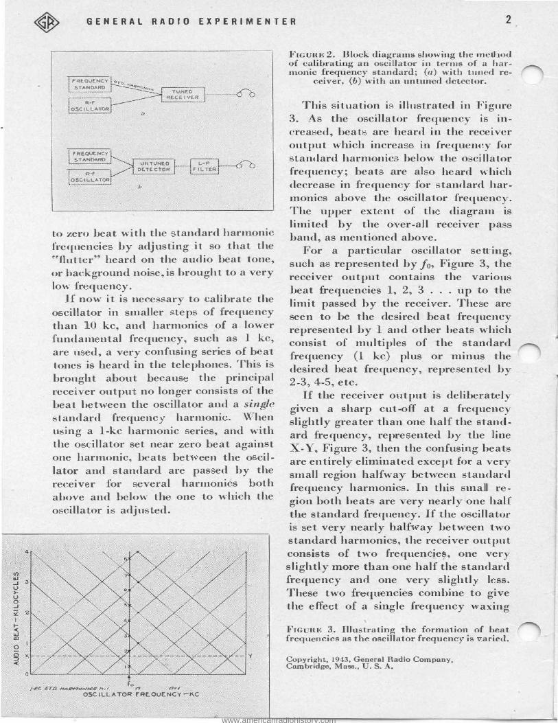
FIGURE 2. Block diagrams showing the mctl od of cal ibrati u,,... an oscillator in terms of a harmonic freq m�'ncy standard; (a) with tuned re-
ceiv r, (b) with an untuncd detect.or.
This ituation i illus·trated in Figure 3. As the oscilla-tor frequency is increa ed, beat are heard in the receiver output ' l ·ch increa in frequency for
tandard harmonic below the o ill a tor frequency; beat are al h ard w hich decrease in frequen y for tandard harmonics above the o cillator frequenc . The upper ext nt of th diagram is limited by the o er-all recei er pa band, as mentioned above.
For a particular oscillator sett ing, su h a represented by f o, Figure 3, the receiver output ontain.s the variou beat frequencies 1, 2, 3 . . . up to the limit passed by th recei er. The e ar
een to be the de ired heat frequenc represented by 1 and other beat whi h consist of multiples of the standard frequency (1 kc) plus or minus th desired beat frequ ncy, repre ented b 2-3, 4-5, etc.
If the recei er output is deliberate! given a sharp cut-off at a frequenc
lightly greater than one half the s-tanclard fr quency, repre ented b the line
-Y, Figure 3, then the confusing beat are entirel elim.inat d except for a ver ·
small region halfwa betw n tandard frequency harmonic . In thi :mall r -
gion both beat are ery nearl one half the standard frequency. If ·the o cilla or is
-et very nearly half ay between ·t o
standard harmonics, the receiver output consists of two :frequen ies, one ver slightly more than one half the standard frequency and one very slightl 1 ss. These two fr qu ci s combine to give ·the effe t of a · gle frequency " axing
FrG RE 3. Illu trati�g the form.atio.11; of 1!eat frequ ncies as the oscillator frequ enc 1s aned.
Copyright, 1943, General Radio Company, Cambridge, Mass., . S. •
www.americanradiohistory.com
3
and waning in inten ity at a rate equal t.o the difference in· frequency. If the oscillator is set so tha-t the waxing and waning takes place ery lo"\ ly, or t.he ��flutter" is brought to a very low frequency, then the oscillator i adjusted wiLh considerable precision to a frequency just halfway between two
Landard harmonic frequencies. For many purposes it i desirable to
a oid the need of tuning a receiver to ucce iv tandard frequency harmon
i s, when an oscillator i being calibrated. An untuned detec-tor can be u ed, as hown in Figure 2b, if separate mean are used for identifying key poin ls on t.he oscillator calibraLion. T avoid confusing beat , a low-pa s filter, wiLh a ut-off frequency slight]y ov r one haH Lhe tan ard fr qu n y, shoul d be used.
Becau e no radio fr qu n y ele -tivi t is pro i<led, a new eries of e Lraneous b at frequenci will be h ard in t.he d tector out.put, if the o cillaLor oulput contains harmonics. Th e b at ar form d a foJlow : while fundamenLal frequency of the o illator being
alibra Led i hanged from one standard :ft_·equency harmoni , n, to he next higher, n + 1, t.he second harmonic of
I
Ci ..i d) r z ::>
• z \,) z .3 0 f ct ([
:I: 4 Dll 0 ...
I fs/a
I I
-fs/4 I I I
{ 5 � ..l I) �
I I fsj5 I '2.fs/s
I I I
OCTOBER, 1943
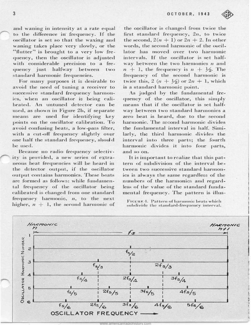
the o cillator i hang d from twice the fir t standard frequency, 2n, to twi the e ond, 2(n + 1) or 2n + 2. In other words, the second harmonic of the o cillator has moved over t' o harmonic inter als. If the oscilla-tor i et halfway between the two harmonic n and n + 1, the freque_nc i n + ,72. The frequen of the se ond harmonic is twice t.his, 2 (n + ,72) or 2n + , whi h is a standard harmoni point. _
As judged b the fundamental frequency of the oscillator, this imply means that if -Lhe oscillator is t half· way between two tandard harmonics a zero beat is heard, due to the econd harm ni . The ond harmonic divides -the fundamental interval in half. 11n1-larl , th third harmonic divide the inter al into three part ; the £ ur h harmonic divid s it into :four parts, and o on.
It i important to r alize that thi pattern of subdivi ion of the int r al b -tween two ucce i e standard harmonics i always the same regardle of -the numb r of the harmoni and regardles of Lhe value of the standard funda-
ntal fre u n y. The pattern is illus-
Fie ne: 4. Pa1-t rn of harrnoni beat which 1.:d->di ide th tandard-frequenc inter al.
.s
I .
fo/z t
..
I I I 2-f�/a I I I I I .2fsj4 I .3f's/4 I I I I I I 3fs/5 I 4f".s/5 I I
• I I
-
0 6 fs/<O 2fs/6 3f.sj6 OSCILLATOR FREQUENCY ----t-
l
www.americanradiohistory.com
l 0: 0 I--< ...I ..J u a I/) 0
GENERAL RADIO EXPERIMENTER 4
FRE..QUE.NCY STANDARD
OSCILLATOR
CRO
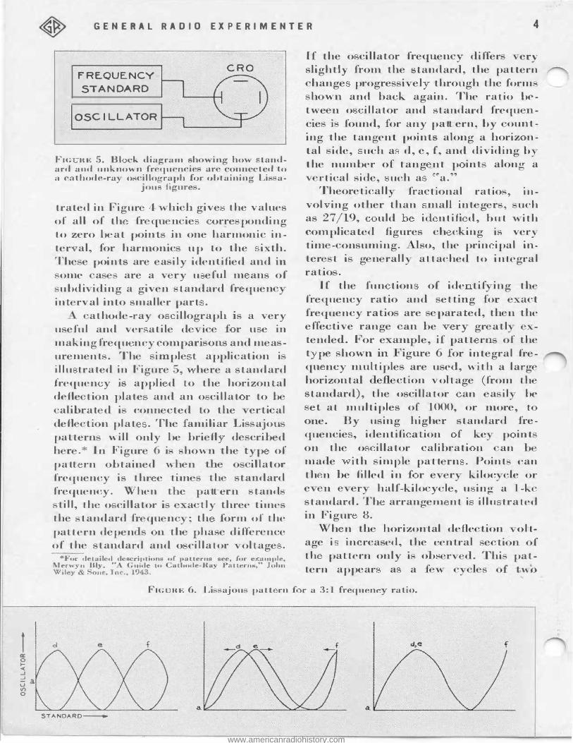
Frc RE 5. BJ ck diagram sh wing how -tandard an<l unknown fr qucncie arc connected lo a cathode-ra o,;cillorrraph £01· obLainin"' Lis a-. fi
t:> JOUS igure .
trated in Figur 4 hi h give the values of all of ·th fr qu n ie orre ponding Lo zero beat point ju one harmonic inter al, for harmonic up to the ixth. 'I he e points are ea ily identified and in , ome a are a v ry u eful m ans of
ubdi iding a given tandard fr quen int rval into smaller part .
athode-ray o illograph is a very useful and ver atile d i :£ r u e in making frequ ncy compari on.s and mea -urement . Th imple t app1ication i iJlu trated in Figure 5, "" here a standard Jrequen y is appli d to the horizontal defle ti n plate and an o cillat r to b
alihrat d i conn cted to the erti al defl ti n plat . The familiar Li a1ou pattern will only be briefl d crihed h r . * In Figure 6 i hown the typ of patt i·n btained wh n ·h illator frequency is thr e Li1n th sta1 dar l frequency. When the pall ern tand
ti11, the o cillator i , a tly three ti1nes the tandard I-i.· qu nc ; th forin of the pa llern de pen n th phase difference of the standard and o cillator oltage .
*For deLail d d s riplion of 1 allerna see, for e ample, Merwy11 Bly. " Guide to atbode-Ra J aLLerns" John \\'.iley & . om·, Jnc., 1943.
'
If the o cillator frequency differ · ery slightly from the standard, the pattern
.hange progre i el through the form h wn and back again. The ratio be
twe n o iJJator and standard frequ I -c1e i found, for any patt ern, by ount-1ng the ·tangent points along a horiz n tal ide, uch a d, e, £, and dividing b the num.ber of tang nt p int alono- a
rtical side, uch a �a." Theoreticall fractional ratios, in.
vol ing other than mall int g r , uch as 27 /19, uld id ntifi d, but " ith complicated figures ch eking is very tim - onsuming. so, the prin ipal inter t i g n rail attached to in Lcgral ralio .
If the fun tion of ide tif in.g ti frequency ratio and euing for e. act frequency ra tio are para ed, th n the effective range an be ry gr atl tended. For e am le, if patt rn. of the t pe hown. in. igure for integral frequ n.cy multiple are used, with a larg horizontal defl c tion · ohage (from Lh standard), the oscillator an a il be
et a t multiples of 1000, or more, t one. By using higher s t andard frequencie , identifi a tion f ke p inl on the o illator calibrati n. an made ith im1 le patt rn . Point can ·th n he filled in :£ r e r kiloc le or e n r half-kilo y ·le, u ing a 1-k standard. Th arrangern nt i illu Lrated in Figur 8.
Wh n th horizontal defte Lion oltage i in rcased, the central th paUern only 1 obs tern appear a a fi
f e ti I Thi pat
f WO
Fie HE 6. Li ajou pau i·n f r a 3:1 frequen y ratio.
d e f d,e f
STANDARD-
www.americanradiohistory.com
5 OCTOBER, 1943
R-F OSCILLATOR D ETE..C"TOR L-P
ANO
� FAMPLIF I ER FILTER
� IOKC � � L-P II) IKC FILTER u � Q
L-P � .. 100 "J
�· FILTER
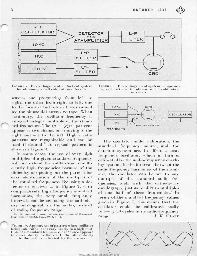
Fie RE 7. Block diagram.of a�dio
_heat
for obtaining small cal1brat1on inter ITI
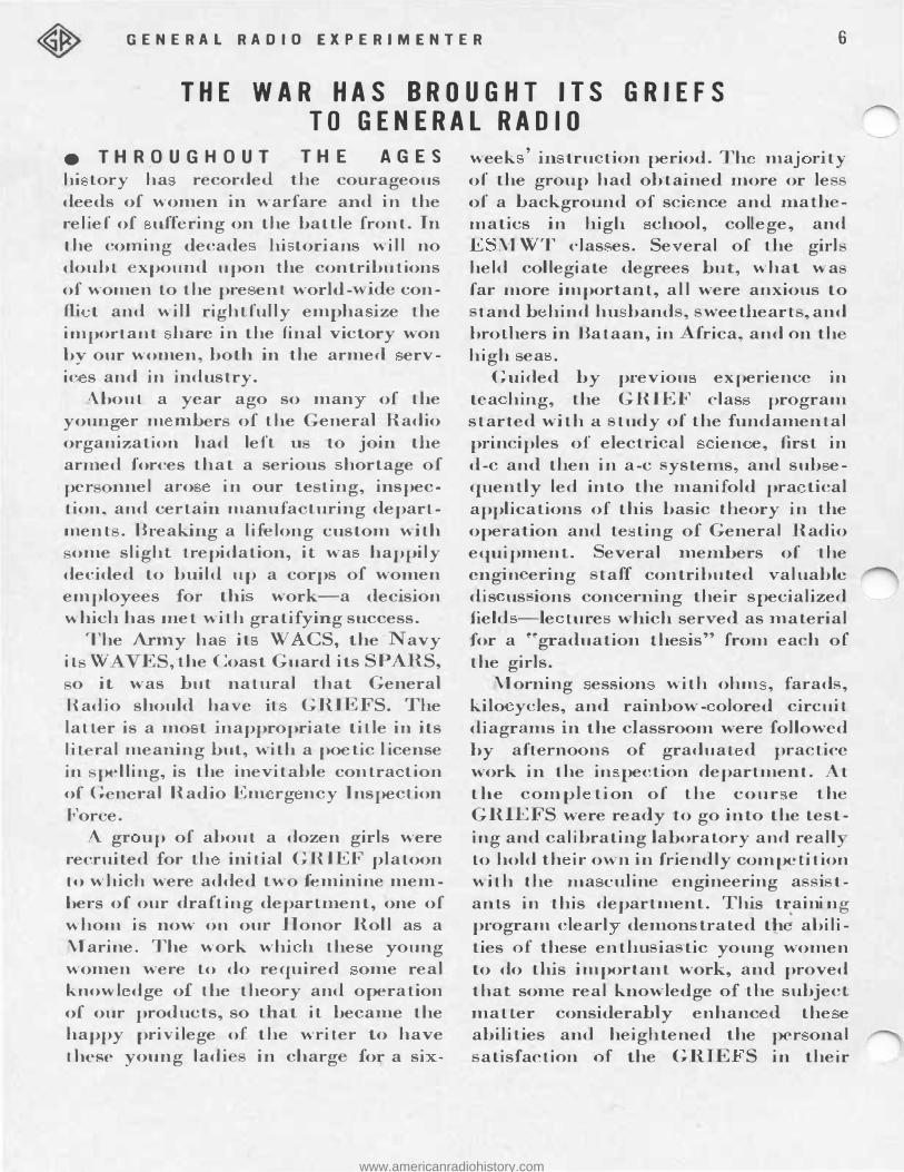
a e , ne progre ing from I f t t o right, ·the oth r from r ight to I ft, due t th forw ard and r turn tra au d by the inu oidal weep ol tag . Wh n
Lationar , the oscill a-tor frequenc i an e act integral m ul t ipl e of ·th ·tandard frequ nc . Th (n + }'2) :l pa ttern app ar a two chain , one moving ·to the right and one to the left. H i gher ratio pa tl rn are recognizabl and an be u d i ( desired.* t pi al p a· tern i
ho n in Figure 9. In om ca e , the u e of ry hicrh
multiple of a gi en tan ard frequen w lll not extend the alibra tion ·to ufficientl hi gh frequencies b cause of the diffi uh of opening out the pa·ttern for
a id ntification of th multiples of t h tan ard frequen . B u ing a detector or recei er a in F i gur 7, wi Lh co1nparati el hi gh frequ nc tandard harm nic , the er mall frequen in Ler a] can be et u ing ·the athod -ra o cillograph in ·t he audio, in. tcacl of radio, frequ nc range.
*F. R. tans 1, Journal of ·the ln.,titution of Electrical Engineer (Briti.-h), June, 1943. p. 73.
FIG RE9. ppearanceofpat·Ler:n.when _scillator
b ino- calibrated is set vet· n arly "to a hig multiple
0of a standat·d frequc�c . On "tra appear
Lo rn e slowl to the ngh·L; the othet· slow] t Lh left as ind ic at ed h ·Lbe arrows.
CRO
, I J
mg RE 8. Bl k dia.,.rmn of s ', L 1n for pr a -
out pal:t t·n to ob lain mall alihration intc-r als.
SOKC
IOKC OSCILLATOR
IKC
STANDARD
Th i l i al r 1HHler calibrat ion, the tandard frequ n our , and th
cl t tor ·t m ar , in ef-£ ct a b al frcquenc o cil l ator, w hi h in turn i calibrated b "the audio-fr quen he k-1 ng sLe m. In th inter - al b t\. en th radio-frequen harmoni f th tandard the o cil lator an be et to an muJLjpJe of th tandard audio fre-qu n , and, ' ith the ca·thode-ra
il l graph, ju t a r adil to multipl f on h alf of Lh fr qu n i
term of tl}e tandard frequ n gi - en ju Figm· 7, thi o il l ator ould b to er 50 c le n1 i l range . LAPP
www.americanradiohistory.com
GENERAL RADIO EXPERIMENTER 6
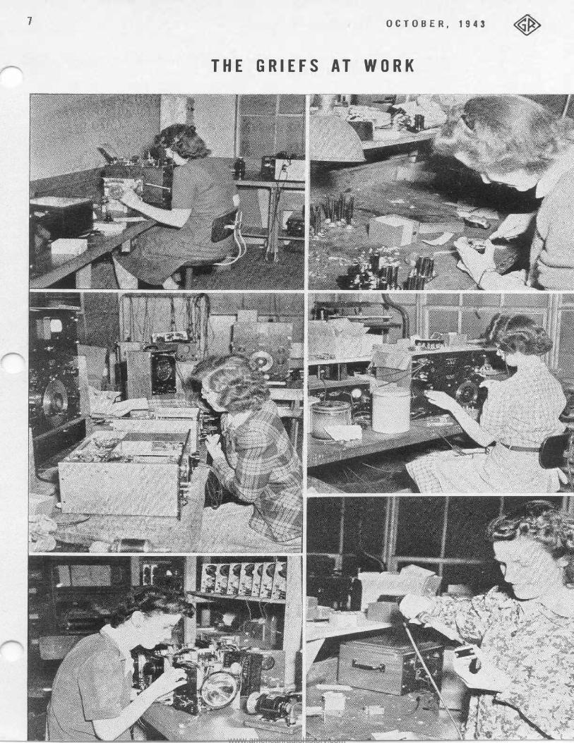
THE WAR HAS BROUGHT ITS GRIEFS TO GENERAL RADIO
e THROUGH OU T THE AGES hi tory ha recorded the courageous deeds of women in warfare and in the relief of uffering on the battle front. In Lhe coming decade hi torians will no doubl xpou:nd upon the contributions of women to the pre ent world- vide confli t and will righlfully empha ize the important hare in t;he final vict;ory won by our women, both in the armed ervic s and in industry.
Ahoul a year ago so man of Lhe young r m m.h r of the eneral Radio organizatjon had left u to join the armed forces that a serious hortage of per 1mel aro in our te ting, inspecLion, and certain manufa turing department . Breaking a lifelong custom with
ome slight trepidation, it wa happily decided to build up a corps of women employees for thi work-a decision which has met wiLh gratifying success.
The Army ha it: W CS, the avy i l W E , the Coast Guard its PARS,
o it was but natural that General Raillo should have it GRI 'FS. The latter is a mo t inappropriale title in its 1 it ral meaning but, with a poetic l icense in pelling, is ·Lhe inevitable contra tion of G n ral Radio Em rg ncy Inspeclion For e.
A gr up of about a dozen girls were recruited for th initial GRIEF platoon to which were added ·two feminine members of our draft ing deparl1nent, one of whom is now on our Honor Roll a a Marine. The work whi h these young women were to do required ome real know] dge of the theory and operation of our products, so that it became the happy privilege of the writer to have these young ladi in charg for a si -
week ' in tru tion period. Th maj rity of the group had obtained more or le of a background of sci nee and math -matics in high chool, college, and E MWT clas es. Se eral of the girl held collegiate degrees but, what wa far more important, all were anxious to
t:and b hind hu band , weetheart , and brolhers in Bataan, in frica, and on th high sea .
Guided by prev1ou experience in tea hing, the GRIEF clas program started with a tudy of the fundamental principles of electri al ien e, first in d-c and then in a-c ystems, and sub equently led into the manifold pra tical applications of this basic theory in the operation and te ting of General Radio equipment. everal members of ·Lhe engin ering taff contributed valuable dis us ions concerning t:heir specialized fie)d -le ·tures which served as material for a H graduation the is'' from each of the girls.
Morning ession with ohm , farad , kilo ycles, and rainbow- olored circuit diagrams in the classroom were followed by afternoons of gradua-t d praclice work in the in pection department. At the com pl ti on of the cour e t:h GRIEFS were ready to go into the testing and calibrating laboratory and reall to hold th ir own in fri ndly compeli-tion with the ma culin engineering a si tan. ts in this department. This tr.aini ng program clearl demon trated th abilities of these enthu ia tic young women to do this important work, and proved that some real knowledge of ·the subject mauer considerably enhanc d the e abilities and heightened the per onal
atisfaction of the GRIE S in their
www.americanradiohistory.com
G E N ERA L RA DI O EXPER IMENT ER 8
w rk and a mpli h1nent . Se eral ( the girl had the ambition to upplement a full da in the l abor a tor with further evening cour u1 mathc1nati and radio.
most happy c pri t de corps ha developed between the GRIEFS and the heretofore lord ly males, a demon-
trated in lun htiro poker game , in certain acti itie of that legendary fello"\ ' ith a ho' and arro"\ ., and in nu1n rou other ' ay .
ince the first group of GRIEF added pulchritude to preci ion in th e Gen ral Radio laboratorie , Unde Sam ha mad further d mand upon our
ma culjne staff and to date fou ·pl atoon of GRIEF have u c i ely joined our per onnel ·to comp nsat for ou1· e paneling llonor Roll. Certain of the
oung ladie ha e found their taJe l and inclination m re adapted to manufacturing ·than tote ting and in p tion act1VJt1 , s -rhat they are now dojng a irrand job in the con truction of precision mica capacitors and a mul titu<le of other con1ponent parts.
War brings its suffering and OJ.Tow ·to a nation, but to eneral Radio it ha introduced a er sp ial and enjo able form of G RIE .
-FioR TIO W. L M :'l
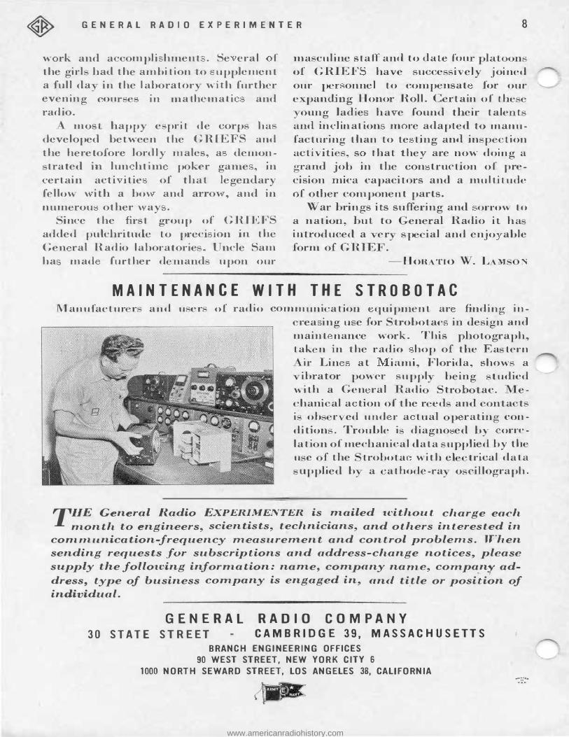
MAINTENANCE W ITH THE STROBOTAC Manufactur r and u er of radio communi ·ation quipm.ent ar findjug in
rea ing u e for 1xobotac in design and
maiu-t nance work. This phot graph, tak n in t,he radio hop of the Ea tern
i:r Lin at iami, Florida, show a ibrator power suppl · b eing t udied
with a Gen ral Radi tr b ac. e-'hani al a tion of the r ed and onta t
i ob r ed und r a tual p ra·ting con
dition . Trouble i d iagno ed by orrelati n of mechanical data u pplie d by th u c f the trobota with el trical data
upplied b a ·athode-ra o cillograph.
THE General Radio EXPERIMENTER is mailed without charge each
month to engineers, scientists, technicians, and others interested in
comrrtunication-frequency rrteasurenl.ent and control problenis. When
sending requests for subscriptions and address-change notices, please
supply the following information: name, company name, cornpanr ad
dress, type of business corrtpany is engaged in, and title or position of
individual.
GENERAL RADIO COMPANY
30 STATE STREET CAMBRIDGE 39, MASSACH USETTS BRANCH ENGI NEERING O FFI CES
90 W EST STREET, NEW YORK CITY 6 1000 NORTH S EWARD STREET, LO S ANGELES 38, CALIFORNIA
www.americanradiohistory.com