Embed Size (px)
Citation preview
CALEFFIDISCAL ® air and dirt separator
546 series 01123/16 NA
Function
Air and dirt separators are used to continuously remove the air and debris contained in the hydronic circuits of heating and cooling systems. The air discharge of these devices is very high. They are capable of automatically removing all of the air present in the system down to the microbubble level. The DISCALDIRT® air and dirt separator also removes any solid impurities in the system. The impurities collect at the bottom of the device and can be flushed through the integal drain shut-off valve. The circulation of fully de-aerated and cleaned water enables the equipment to operate under optimum conditions, free from noise, corrosion, or mechanical damage.
Insulation shells are available separately for field installation on the brass DISCALDIRT®.
Replaces 01123/15 NAISO 9001 No. 0003
ACCREDITED
ISO 9001 FM 21654
Product range
54609 series DISCALDIRT® air and dirt separator in brass..............................................................................................connections 1", 1-¼" sweat
546016A DISCALDIRT® air and dirt separator in brass...................................................................................................connection 1" NPT male
546 series DISCALDIRT® air and dirt separator in steel.........................................................................................connections 2"-6" ANSI flanged
NA546 series DISCALDIRT® air and dirt separator in steel, ASME & CRN.........................................................connections 2-½" to 14" ANSI flanged
NA546050T DISCALDIRT® air and dirt separator in steel, ASME & CRN......................................................................connections 2" NPT threaded
Technical specifications
Brass body air and dirt separators
Materials - body: brass - dirt separation chamber: brass - air vent body: brass - internal element: glass reinforced nylon, PA66GF30 - air vent float: PP - air vent float guide pin: stainless steel - air vent float linkages: stainless steel - spring: stainless steel - seals: EPDM - bottom drain shut-off valve: brass
PerformanceSuitable fluids: water, glycol solutionMax. percentage of glycol: 50%Max. working pressure: 150 psi (10 bar)Temperature range: 32–250°F (0–120°C)Air separation efficiency: 100% removal to microbubble levelParticle separation capacity: to 5 µm (0.2 mil)
Connections - main: 1", 1-¼" sweat; 1" NPT male - drain shut-off valve: ¾" garden hose (GHT)
Steel body air and dirt separators
Materials - body: epoxy resin painted steel - air vent body: brass - mesh internal element: stainless steel - air vent float: PP - air vent float guide pin: stainless steel - air vent float linkages: stainless steel - spring: stainless steel - seals: EPDM - bottom drain shut-off valve: brass - side drain shut-off valve: brass PerformanceSuitable fluids: water, glycol solutionMax. percentage of glycol: 50%Max. working pressure: 150 psi (10 bar)Temperature range (vessel): 32–270°F (0–132°C)Air separation efficiency: 100% removal to microbubble levelParticle separation capacity: to 5 µm (0.2 mil)
Connections - flanged: 2½"–14" ANSI B16.5 150 CLASS RF - threaded: 2" NPT male - bottom drain valve: sizes 2 – 6 inch: 1" NPT female sizes 8 - 14 inch: 2" NPT female - side drain shut-off valve: ¾" GHT -Agency approvalNA546 series designed and built in accordance with Section VIII, Division 1 of the ASME Boiler and Pressure Vessel Code and tagged, registered with the National Board of Boiler and Pressure Vessel Inspectors, stamped for 150 psi (10 bar) working pressure, with ASME U stamp, CRN registered. 14" is CRN pending, consult Caleffi.
BC
A
E
F
D
A
BC
F
DE
F
AD
E
BG
3855
2
H
C
3 1/8 ”
A
BC
F
DE
F
A
DE
BG
3855
2
H
C
3 1/8 ”
B
F
G
AD
E
3855
2
H
C
J
3 1/8 ”3 1/
8”
NA546050TM
NA546M
CC
F
AD
E
BG
3855
2
H
C
3 1/8”
A
BC
F
DE
F
A
DE
BG
3855
2
H
C
3 1/8”
B
F
G
AD
E
3855
2
H
C
J
3 1/8”3 1/
8”
NA546050TM
NA546_M
F
AD
E
BG
3855
2
H
C
3 1/8 ”
ABC
F
DE
F
A
DE
BG
3855
2
H
C
3 1/8 ”
B
F
G
AD
E
3855
2
H
C
J
3 1/8 ”3 1/
8”
NA546050TM
NA546M
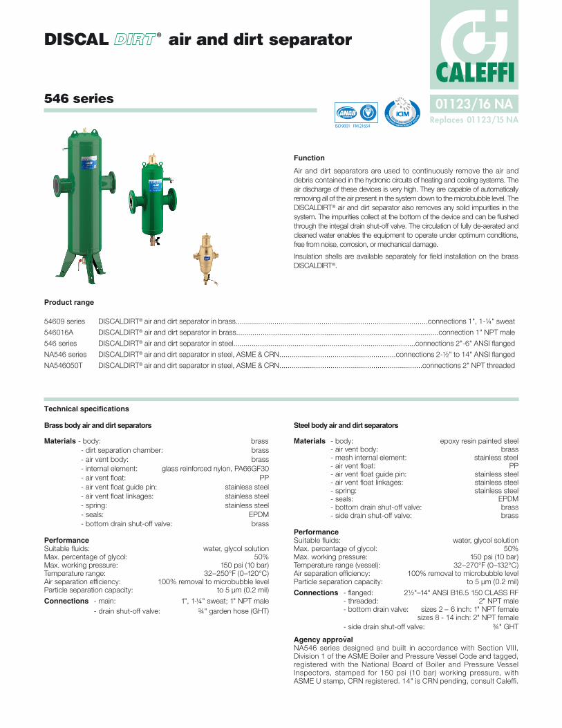
NOTE: Drawings may not reflect the actual size of the separators.
* Add prefix NA to flanged code number when ordering ASME tagged and registered with the National Board of Boiler and Pressure Vessel Inspector and CRN registered.
This model is ASME tagged and registered with the National Board of Boiler and Pressure Vessel Inspector and CRN registered.
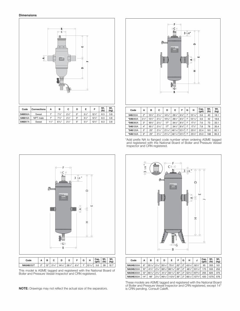
Dimensions
Code Connections A B C D E F Wt. (lb)
Wt. (kg)
546096A Sweat 1" 73⁄8" 21⁄8" 5" 51⁄2" 123⁄4" 8.3 3.8
546016A NPT male 1" 73⁄8" 21⁄8" 5" 51⁄2" 123⁄4" 8.3 3.8
546097A Sweat 11⁄4" 63⁄16" 21⁄8" 5" 51⁄2" 123⁄4" 8.3 3.8
Code A B C D E F G H Cap. (gal)
Wt. (lb)
Wt. (kg)
546050A 2" 133⁄4" 23⁄16" 149⁄16" 281⁄4" 65⁄8" 1" 1311⁄16" 3.6 40 18.1
*546060A 21⁄2" 133⁄4" 23⁄16" 149⁄16" 281⁄4" 65⁄8" 1" 1311⁄16" 3.6 42 18.6
*546080A 3" 183⁄8" 23⁄16" 17" 341⁄2" 8 5⁄8" 1" 171⁄2" 7.6 73 33.1
*546100A 4" 181⁄2" 23⁄16" 17" 341⁄2" 8 5⁄8" 1" 171⁄2" 7.8 78 35.4
*546120A 5" 25" 23⁄16" 211⁄16" 4611⁄16" 123⁄4" 1" 255⁄8" 22.4 181 82.1
*546150A 6" 25" 23⁄16" 211⁄16" 4611⁄16" 123⁄4" 1" 255⁄8" 23.0 188 85.3
Code A B C D E F G H Cap. (gal)
Wt. (lb)
Wt. (kg)
NA546050T 2" 13" 23⁄16" 149⁄16" 281⁄4" 65⁄8" 1" 1311⁄16" 3.6 28 12.7
Code A B C D E F G H J Cap. (gal)
Wt. (lb)
Wt. (kg)
NA546200A 8" 357⁄16" 23⁄16" 353⁄16" 753⁄8" 20" 2" 433⁄16" 923⁄4" 95 355 161
NA546250A 10" 413⁄4" 23⁄16" 389⁄16" 8613⁄16" 26" 2" 481⁄4" 1011⁄16" 175 555 252
NA546300A 12" 467⁄16" 23⁄16" 411⁄8" 9311⁄16" 30" 2" 529⁄16" 1075⁄16" 255 825 375
NA546350A 14" 48" 23⁄16" 465⁄16" 1123⁄8" 36" 2" 661⁄16" 1273⁄4" 420 1270 576
These models are ASME tagged and registered with the National Board of Boiler and Pressure Vessel Inspector and CRN registered, except 14" is CRN pending. Consult Caleffi.

The process of air formationThe amount of air which can remain dissolved in a water solution is a function of pressure and temperature. This relationship is governed by Henry’s law and the graph demonstrates the physical phenomenon of the air release from water. As an example, at a constant absolute pressure of 30 psi (2 bar), if the water is heated from 65ºF (18ºC) to 170ºF (75ºC), the amount of air released by the solution is equal to 1.8 gallons of air per 100 gallons of water. According to this law it can be seen that the amount of air released increases with temperature rise and pressure reduction. The air comes in the form of micro-bubbles of diameters in the order of tenths of a millmeter.
In heating and cooling systems there are specific points where this process of formation of micro-bubbles takes place continuously in the boiler and in any device which operates under conditions of cavitation.
Cavitation and micro-bubblesMicro-bubbles deve lop where the fluid velocity is very high with the corre-sponding reduction in pres-sure. These points are typi-cally pump impellers and valve ports.
T h e s e a i r a n d v a p o r m i c r o - b u b b l e s , t h e f o r m a t i o n of which is enhanced in the case of non-deaerated water, may sub-sequently implode due to the cavitation phenomenon.
Boiler micro-bubblesMicro-bubbles are formed continuously on the surface separating the water from the combustion chamber due to the fluid tempera-ture. This air, carried by the water, collects in the critical points of the circuit from where it must be removed.
Some of this air is reabsorbed in the presence of colder surfaces.
Solubility of air in water
1
2 2
3
1
2
3
1
1
2
33
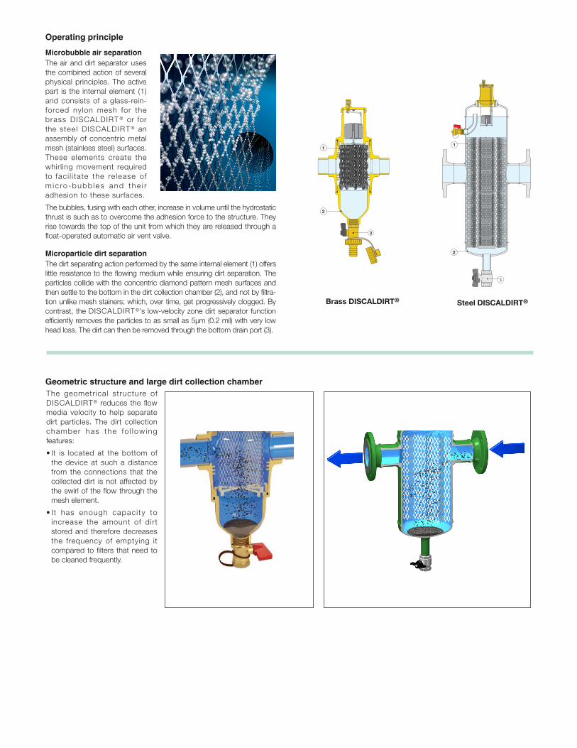
Operating principle
Microbubble air separationThe air and dirt separator uses the combined action of several physical principles. The active part is the internal element (1) and consists of a glass-rein-forced nylon mesh for the brass DISCALDIRT ® or for the steel DISCALDIRT ® an assembly of concentric metal mesh (stainless steel) surfaces. These elements create the whirling movement required to faci l i tate the re lease of m ic ro -bubb les and the i r adhesion to these surfaces.
The bubbles, fusing with each other, increase in volume until the hydrostatic thrust is such as to overcome the adhesion force to the structure. They rise towards the top of the unit from which they are released through a float-operated automatic air vent valve.
Brass DISCALDIRT® Steel DISCALDIRT®
Microparticle dirt separationThe dirt separating action performed by the same internal element (1) offers little resistance to the flowing medium while ensuring dirt separation. The particles collide with the concentric diamond pattern mesh surfaces and then settle to the bottom in the dirt collection chamber (2), and not by filtra-tion unlike mesh stainers; which, over time, get progressively clogged. By contrast, the DISCALDIRT ®'s low-velocity zone dirt separator function efficiently removes the particles to as small as 5μm (0.2 mil) with very low head loss. The dirt can then be removed through the bottom drain port (3).
3
4
1
2
1
2
3
4
1
2
3
4
The geometrical structure of DISCALDIRT® reduces the flow media velocity to help separate dirt particles. The dirt collection chamber has the fo l low ing features:
• It is located at the bottom of the device at such a distance from the connections that the collected dirt is not affected by the swirl of the flow through the mesh element.
• I t has enough capaci ty to increase the amount of dirt stored and therefore decreases the frequency of emptying it compared to filters that need to be cleaned frequently.
Geometric structure and large dirt collection chamber
1
2 2
3
1
2
3
1
1
2
33
Steel DISCALDIRT®
5
2
1
3
8
4
7
6
3
1
2
4
6
3
1
2
4
75
2
1
3
8
4
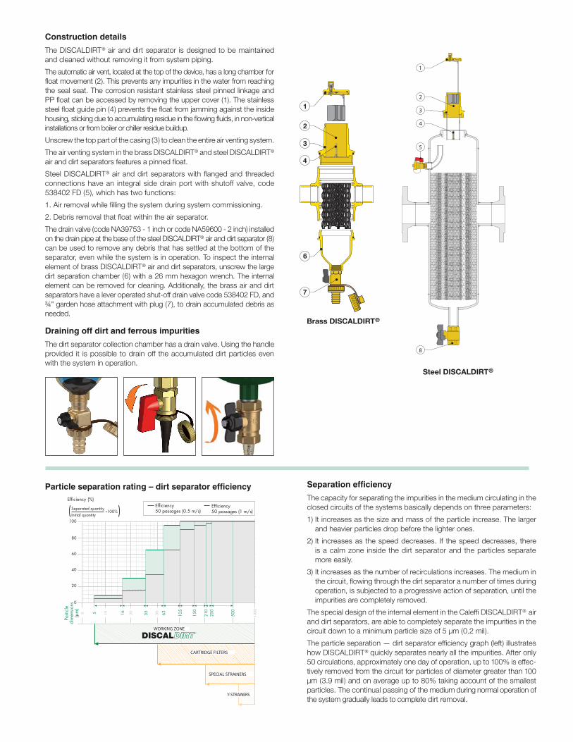
Construction detailsThe DISCALDIRT® air and dirt separator is designed to be maintained and cleaned without removing it from system piping.
The automatic air vent, located at the top of the device, has a long chamber for float movement (2). This prevents any impurities in the water from reaching the seal seat. The corrosion resistant stainless steel pinned linkage and PP float can be accessed by removing the upper cover (1). The stainless steel float guide pin (4) prevents the float from jamming against the inside housing, sticking due to accumulating residue in the flowing fluids, in non-vertical installations or from boiler or chiller residue buildup.
Unscrew the top part of the casing (3) to clean the entire air venting system.
The air venting system in the brass DISCALDIRT® and steel DISCALDIRT® air and dirt separators features a pinned float.
Steel DISCALDIRT® air and dirt separators with flanged and threaded connections have an integral side drain port with shutoff valve, code 538402 FD (5), which has two functions:
1. Air removal while filling the system during system commissioning.
2. Debris removal that float within the air separator.
The drain valve (code NA39753 - 1 inch or code NA59600 - 2 inch) installed on the drain pipe at the base of the steel DISCALDIRT® air and dirt separator (8) can be used to remove any debris that has settled at the bottom of the separator, even while the system is in operation. To inspect the internal element of brass DISCALDIRT® air and dirt separators, unscrew the large dirt separation chamber (6) with a 26 mm hexagon wrench. The internal element can be removed for cleaning. Additionally, the brass air and dirt separators have a lever operated shut-off drain valve code 538402 FD, and ¾" garden hose attachment with plug (7), to drain accumulated debris as needed.
Draining off dirt and ferrous impuritiesThe dirt separator collection chamber has a drain valve. Using the handle provided it is possible to drain off the accumulated dirt particles even with the system in operation.
Brass DISCALDIRT®
5
2
1
3
8
4
7
6
3
1
2
4
6
3
1
2
4
7
5
2
1
3
8
4
Steel DISCALDIRT®
Particle separation rating – dirt separator efficiency
1000
Efficiency50 passages (0.5 m/s)
502010
40
20
0
60
80
100
Efficiency (%)Efficiency50 passages (1 m/s)
Parti
cle
dim
ensi
ons
(µm
)0 5 16 35 63 10
5
150
250
210
500
WORKING ZONE
CARTRIDGE FILTERS
SPECIAL STRAINERS
Y-STRAINERS
Separated quantityInitial quantity
.100%( )
Tests in a specialized laboratory
TNO - Science and Industry (NL)
®
Separation efficiencyThe capacity for separating the impurities in the medium circulating in the closed circuits of the systems basically depends on three parameters:
1) It increases as the size and mass of the particle increase. The larger and heavier particles drop before the lighter ones.
2) It increases as the speed decreases. If the speed decreases, there is a calm zone inside the dirt separator and the particles separate more easily.
3) It increases as the number of recirculations increases. The medium in the circuit, flowing through the dirt separator a number of times during operation, is subjected to a progressive action of separation, until the impurities are completely removed.
The special design of the internal element in the Caleffi DISCALDIRT® air and dirt separators, are able to completely separate the impurities in the circuit down to a minimum particle size of 5 μm (0.2 mil).
The particle separation — dirt separator efficiency graph (left) illustrates how DISCALDIRT® quickly separates nearly all the impurities. After only 50 circulations, approximately one day of operation, up to 100% is effec-tively removed from the circuit for particles of diameter greater than 100 μm (3.9 mil) and on average up to 80% taking account of the smallest particles. The continual passing of the medium during normal operation of the system gradually leads to complete dirt removal.

Hydraulic characteristics
0.56
G (l
/s)
(gpm
)
(kPa)
2.8
1.4
0.33
0.39
0.44
0.50
0.69
0.83
0.97 1.
11.
25 1.7
1.9
2.2
2.5
3.3
3.9
4.4
5.0
6.9 11 12
5.6 8.3
9.7
14
2” 2 1/
2”
2817 19 22 25
3” 4”
33 39 44 50 56
5” 6”
0.1
0.05
0.090.080.07
0.06
0.0350.040.045
0.12
0.140.160.18
0.25
0.3
0.35
0.2
1
0.1
0.2
0.5
0.90.80.7
0.6
0.12
0.140.160.18
0.25
0.30.350.40.45
1.2
1.41.61.8
2.5
3
2
1
0.5
0.90.80.7
0.6
0.450.4
0.090.080.07
0.06
0.025
0.03
0.02
(ft of water)
ΔP (ft of water)
100105 20 50
1000200
500
0.1
0.05
0.090.080.07
0.06
0.0350.040.045
0.12
0.140.160.18
0.25
0.3
0.35
0.2
1
0.5
0.90.80.7
0.6
0.450.4
0.025
0.03
0.02
6 7 8 9 12 14 16 18 25 3 0 35 40 45 60 70 80 90 120
140
160
180
250
400
450
300
350
600
700
800
900
1.2
1.41.61.82 6
4.5
1.2
1.41.61.82
69 83 97 111
125
200012
0014
0016
0018
00
43.5
5
12”
10”
8”
4.3
4.0
3.5
3.0
2.7
2.2
0.270.
250.
220.
190.
170.
14
1” 1 1/
4”
14”
ft of water x .433 = psi
Brass body Steel body
Size 1" 1¼" 2" 2 ½" 3" 4" 5" 6" 8" 10" 12" 14"
4.0 f/sGPM 9 10 37 63 95 149 259 380 625 980 1,410 1,950
l/s 0.5 0.6 2.4 4.0 6.0 9.4 16.3 24.6 40 62 89 123
10.0 f/sGPM 22 30 89 150 227 355 816 904 1,570 2,450 3,530 4,550
l/s 1.4 1.9 5.6 9.5 14.3 22.4 51.5 57 99 154 223 287
Cv 32 40 87 174 208 324 520 832 1,109 1,387 1,664 1,967

1.4
1.8
0.060
0.040
0.20
0.27
0.530.47
2.002.332.67
0.23
0.30
0.40
0.17
0.33
0.67
1.67
3.33 3.00
0.60
1.00
1.33
0.13
0.10
0.053
0.033
0.0670.047
G (l/
s) (g
pm)
4.4
8.8
19.8
39.0
5.3
6.15
7.04
5
7.9
11.0
13.2
15.4
17.6
22.0
23.0
27.0
31.0
35.0
0.5
1
2
5
10
0.1
0.2
9876
4
3
1.6
1.2
0.8
0.60.7
0.9
0.4
0.3
0.18
0.12
0.160.14
∆P (kPa)
0.25
0.35
0.45
2.5
3.5
4.5
0.83
1.17
1.50
0.083
0.12
0.15
2.2
2.6
3.0
3.5
3.96
1.98
0.20
0.26
0.073
1.51.31.21.00.9
0.58
0.41
0.23
0.17
0.12
0.090.10
0.13
0.06
0.04
0.026
0.017
0.0230.020
(PSI)
0.036
0.05
0.07
0.36
0.51
0.650.71
0.16
0.029
0.016
∆p (ft. of water)
0.28
0.56
1.25 2.50.
33
0.39
0.44 0.5
0.70
0.83
0.97
1.11 1.4
1.45 1.7
1.96 2.2
0.14
0.16
0.19
0.22
0.25
0.12
DISCALDIRT®
curve1”– Cv =32
Y-strainer curve1” - Cv=19
Comparison of head losses: air and dirt separator to Y-strainersY-strainers entrap dirt within a basket made of stainless steel or brass mesh, selected for the size of the largest particle. Particles smaller than the mesh size may pass through. On most Y-strainers, the basket must be removed periodically to clear the trapped debris. As the debris collects in the basket, flow is impeded resulting in increasing pressure drop and therefore higher head loss. The dirt separation function in the DISCALDIRT® performs exactly as it does in the DIRTCAL®, utilizing the low-velocity-zone principle. The flow velocity of fluid flowing into the dirt separation chamber is greatly reduced causing the entrained dirt par-ticles to drop due to their density.
The internal element provides surfaces that assist in separating dirt particles and guide them downward to ultimately settle to the bottom of the separator. The dirt separator only creates about 25% of the pressure drop of a comparable sized, clean basket strainer, depending on mesh size and amount of filtered debris. These head losses are not affected by the amount of dirt collected.
Replacement parts
Drain valves (5) & (7), code 538402 FD. Drain valves (8), separator sizes 2" - 6", code NA39753; separator sizes 8" -14", code NA59600.
Insulation shellsThe brass DISCALDIRT® 5460 series can be supplied with the optional insulated cover, code CBN546002 series (purchased separately), to minimize heat loss.
Technical specificationsMaterial: closed cell expanded PE-XThickness: 25/64" (10 mm)Density: - inner part 1.9 lb/ft3 (30 kg/m3) - outer part: 5.0 lb/ft3 (80 kg/m3)Thermal conductivity (DIN 52612): - at 32°F (0°C): 0.263 BTU·in/hr·ft2·°F (0.038 W/(m·K) - at 104°F (40°C): 0.312 BTU·in/hr·ft2·°F (0.045 W/(m·K)Coefficient of resistance to water vapor (DIN 52615): >1,300Working temperature range: 32–230°F (0–110°C)Reaction to fire (DIN 4102): CLASS B2
Removing insulation and draining impurities
1. Remove the insulation by taking off the bottom casing of the collection chamber first, and if necessary, the top insulation casing later.
3. Flush out the debris by turning the handle to open the drain valve.
4. When finished, replace the insulation shells.
F39807
59829
59756
F39807
59829
59756
Code Size
CBN5460021", 1-¼"
DISCALDIRT®
A replacement air vent assembly for the brass DISCALDIRT® 5460 series is code 59829; for the steel DISCALDIRT® 546, NA546 series is code 59756.
The moving parts that control air vent-ing are accessed simply by removing
the upper cover. Replacement cap and float assem-bly for all versions o f t h e b r a s s D I S C A L D I R T ® 5460 ser ies is code F39807.
When cleaning, simply unscrew the portion of the body containing the automatic air vent.

Caleffi North America, Inc.3883 W. Milwaukee RoadMilwaukee, WI 53208Tel: 414-238-2360 · Fax: [email protected] · www.caleffi.com© Copyright 2016 Caleffi North America, Inc.
We reserve the right to change our products and their relevant technical data, contained in this publication, at any time and without prior notice.
5460 series DISCALDIRT® – brass with sweat and NPT connectionsAir and dirt separator complete with brass automatic air vent containing pinned float. Connections for horizontal pipes, sweat connections for 1" and 1-1/4" sizes, NPT male connection for 1". Brass body and dirt separation chamber. EPDM seals. Glass reinforced nylon PA66G30 internal mesh element, removable for cleaning. PP float. Stainless steel float linkages. Stainless steel float guide pin. Brass drain shut-off valve. Maximum working pressure, 150 psi (10 bar). Temperature range 32 to 250°F (0 to 120°C). Glycol maximum 50%. Air separation efficiency: 100% removal to micro-bubble level. Particle separation capacity: to 5 μm (0.2 mil). Drain shut-off valve with ¾" garden hose connection. Pre-formed insulation shells available for field installation.
546 series DISCALDIRT® – flanged steelAir and dirt separator in steel with brass side drain valve and automatic air vent with pinned float. Flanged ANSI B16.5 CLASS 150 RF connections from 2" to 6" for horizontal pipes. Epoxy resin painted steel body. EPDM seal. Stainless steel internal mesh element. PP float. Stainless steel float linkages. Stainless steel float guide pin. Supplied with drain ball valve with T handle, brass body and 1" NPT female connection, code NA39753, and side drain port supplied with integral brass shutoff valve, code 538402 FD, and ¾" garden hose connection. Maximum working pressure, 150 psi (10 bar). Vessel working temperature range 32 to 270°F (0 to 132°C). Glycol maximum 50%. Air separation efficiency: 100% removal to micro-bubble level. Particle separation capacity: to 5 μm (0.2 mil).
NA546 series DISCALDIRT® – flanged steel, ASME & CRNAir and dirt separator in steel with brass side drain valve and automatic air vent with pinned float. Flanged ANSI B16.5 CLASS 150 RF connections from 2" to 14", and 2" NPT threaded connections, for horizontal pipes. Epoxy resin painted steel body. EPDM seal. Stainless steel internal mesh element. PP float. Stainless steel float linkages. Stainless steel float guide pin. Supplied with brass drain ball valve, for 2" to 6" size separators 1" NPT female with T handle, code NA39753, for 8" to 14" size separators 2" NPT female with lever handle, code NA59600. Side drain port supplied with integral brass shutoff valve, code 538402 FD, and ¾" garden hose connection. Maximum working pressure, 150 psi (10 bar). Vessel working temperature range 32 to 270°F (0 to 132°C). Glycol maximum 50%. Air separation efficiency: 100% removal to micro-bubble level. Particle separation capacity: to 5 μm (0.2 mil). Designed and built in accordance with Section VIII, Division 1 of the ASME Boiler and Pressure Vessel Code and tagged and registered with National Board of Boiler and Pressure Vessel Inspector, CRN registered (size 14" pending, contact Caleffi), and stamped for 150 psi (10 bar) working pressure, with ASME U stamp.
SPECIFICATION SUMMARIES
InstallationDISCALDIRT® units may be used in both heating and cooling sys-tems, to ensure continuous air and dirt elimination. The units should be installed after the boiler and on the pump suction side, as these are the points where the formation of micro-bubbles is greatest.
DISCALDIRT® air and dirt separators must be installed vertically. In installation conditions where inspection is not possible, it is recom-mended that the venting valve cap is replaced by a Caleffi part num-ber R59681 hygroscopic safety vent. The standard replacement cap code number is 59199.
CHILLER
CHILLER CHILLER
CHILLER
CHILLER
CHILLER
CHILLER