Embed Size (px)
Citation preview
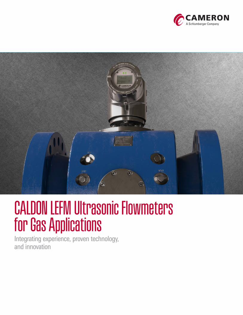
CALDON LEFM Ultrasonic Flowmeters for Gas ApplicationsIntegrating experience, proven technology, and innovation
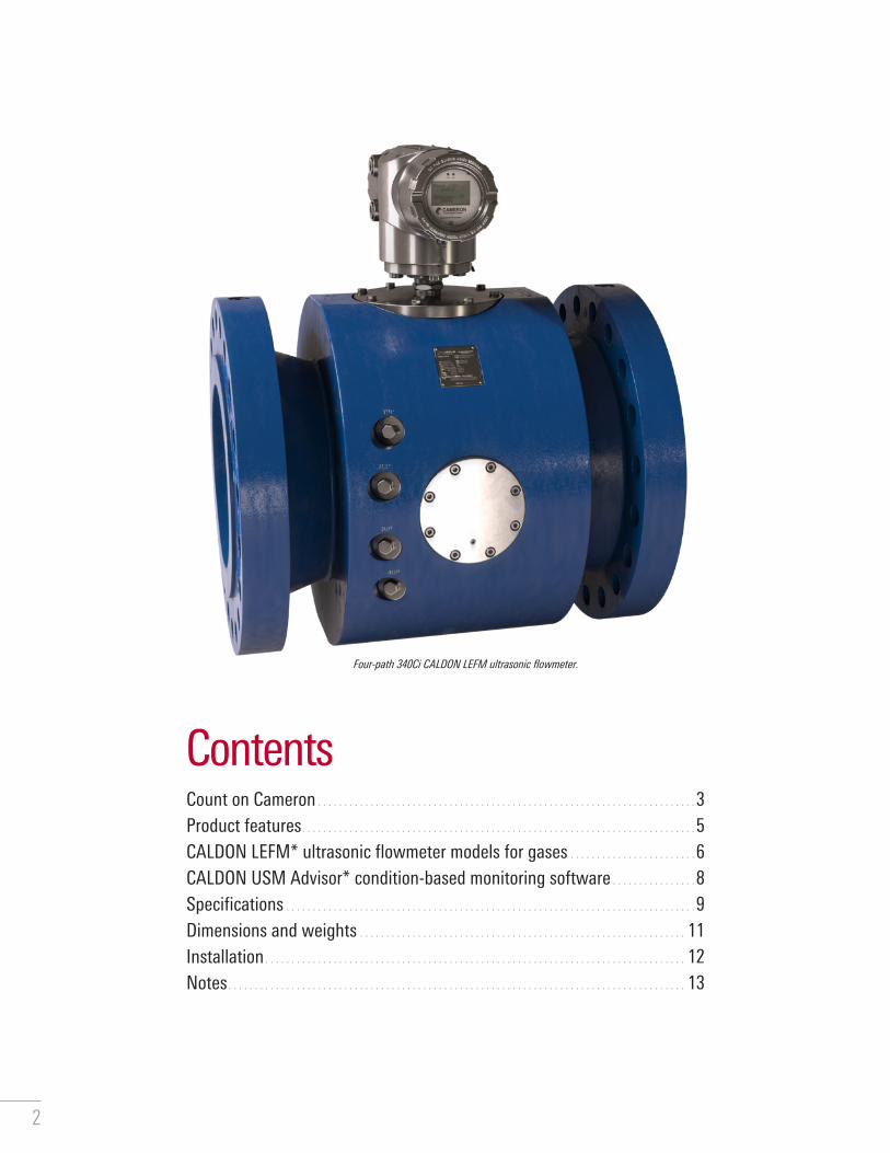
ContentsCount on Cameron � � � � � � � � � � � � � � � � � � � � � � � � � � � � � � � � � � � � � � � � � � � � � � � � � � � � � � � � � � � � � � � � � � � � � � � � 3Product features � � � � � � � � � � � � � � � � � � � � � � � � � � � � � � � � � � � � � � � � � � � � � � � � � � � � � � � � � � � � � � � � � � � � � � � � � � � 5CALDON LEFM* ultrasonic flowmeter models for gases � � � � � � � � � � � � � � � � � � � � � � � � 6CALDON USM Advisor* condition-based monitoring software � � � � � � � � � � � � � � � � 8Specifications � � � � � � � � � � � � � � � � � � � � � � � � � � � � � � � � � � � � � � � � � � � � � � � � � � � � � � � � � � � � � � � � � � � � � � � � � � � � � � 9Dimensions and weights � � � � � � � � � � � � � � � � � � � � � � � � � � � � � � � � � � � � � � � � � � � � � � � � � � � � � � � � � � � � � � 11Installation � � � � � � � � � � � � � � � � � � � � � � � � � � � � � � � � � � � � � � � � � � � � � � � � � � � � � � � � � � � � � � � � � � � � � � � � � � � � � � � � 12Notes � � � � � � � � � � � � � � � � � � � � � � � � � � � � � � � � � � � � � � � � � � � � � � � � � � � � � � � � � � � � � � � � � � � � � � � � � � � � � � � � � � � � � � � 13
Four-path 340Ci CALDON LEFM ultrasonic flowmeter.
2

CALDON LEFM ultrasonic flowmeters provide the industry with durable, stable, and low-cost-of-ownership ultrasonic measurement options� Cameron is constantly developing cutting-edge ultrasonic technology to better meet industry demands for custody transfer� Our multipath inline ultrasonic flowmeters are backed by more than 50 years of experience and a history of technological firsts for their use�
Designed to help satisfy customer needs with the broadest product range for custody transfer of natural gas, CALDON LEFM flowmeters provide
■ improved meter reliability over a wide range of application conditions ■ improved safety for technicians when replacing transducers ■ simplified installation, reduced meter footprint, and overall metering
section weight ■ reduced maintenance�
The CALDON LEFM ultrasonic flowmeters create a unique offering to address operator concerns by integrating three crucial design elements:
■ engineered transducer configurations in industry-standard four-path flowmeters and premium-performance eight-path flowmeters to maximize measurement accuracy without the need for flow conditioners, reducing upstream piping
■ optional proprietary coating that effectively mitigates potential corrosion and contamination from components in the gas stream
■ transducers fully isolated from the gas in industry's first custody-transfer gas ultrasonic meter, enabling safe replacement in the unlikely event that a transducer replacement is required�
CALDON LEFM flowmeter firsts
1965–70 First chordal multipath flowmeters
1970–75 First nuclear reactor coolant application
1974–75 First crude oil application
1994–99 First measurement uncertainty recapture uprate at nuclear facilities
1995 First military-specification flowmeter
2003 First application for custody transfer of liquid hydrocarbons
2005 First application for custody transfer of LNG
2008 First application for custody transfer of heavy, viscous crude oils up to 3,000 mm2/s
2010 First CALDON LEFM 380Ci flowmeters installed on natural gas pipelines with isolated transducers
Count on Cameron
3

Advantages ■ Compliance with American Gas Association (AGA) Report 9,
International Organization of Legal Metrology (OIML) Recommendation R 137, and ISO 17089-1
■ Four- and eight-path chordal designs for optimal linearity and repeatability
■ Industry-leading eight-path chordal design with dramatically reduced sensitivity to swirl and asymmetry effects
■ 5-diameter minimum upstream pipe run and no requirement for flow conditioner, which reduces total cost of ownership
■ Advanced signal processing with real-time diagnostic analysis
■ Transducers that are isolated from the process and outside the pressure boundary for ease of service, if required
■ No recalibration or zeroing required if transducer is replaced ■ In-house transducer manufacturing for maximum quality control ■ Internal resistance temperature detector (RTD) for thermal
expansion compensation ■ Continuous logging capabilities ■ Optional corrosion- and contamination-resistant internal coating
Eight-path 380Ci CALDON LEFM ultrasonic flowmeter.
4
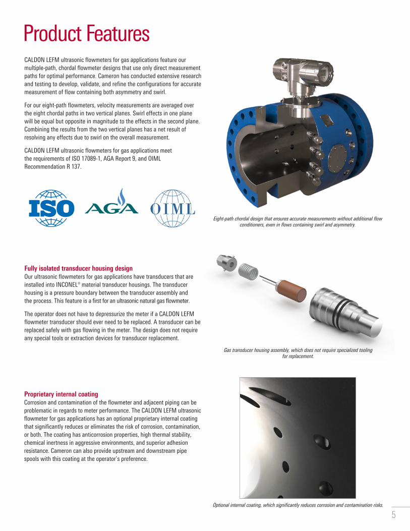
Product FeaturesCALDON LEFM ultrasonic flowmeters for gas applications feature our multiple-path, chordal flowmeter designs that use only direct measurement paths for optimal performance� Cameron has conducted extensive research and testing to develop, validate, and refine the configurations for accurate measurement of flow containing both asymmetry and swirl�
For our eight-path flowmeters, velocity measurements are averaged over the eight chordal paths in two vertical planes� Swirl effects in one plane will be equal but opposite in magnitude to the effects in the second plane� Combining the results from the two vertical planes has a net result of resolving any effects due to swirl on the overall measurement�
CALDON LEFM ultrasonic flowmeters for gas applications meet the requirements of ISO 17089-1, AGA Report 9, and OIML Recommendation R 137�
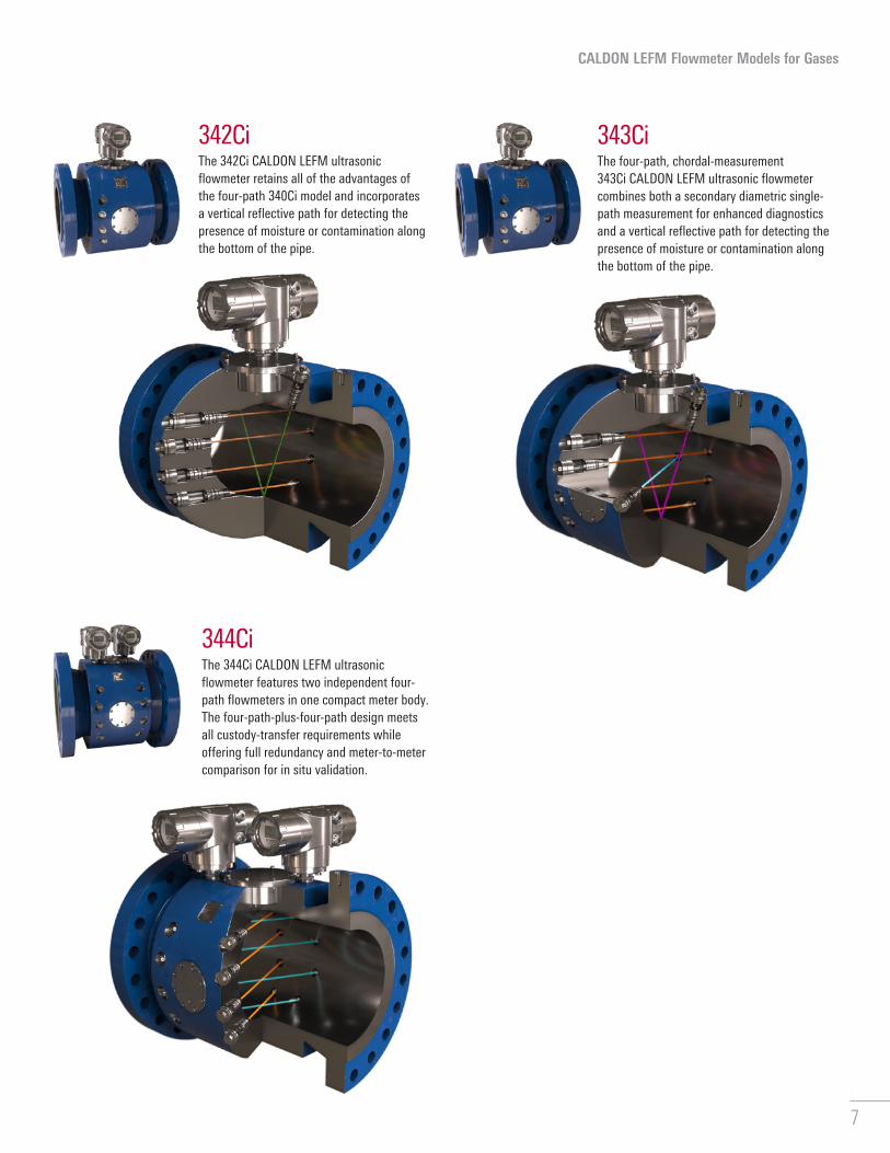
Fully isolated transducer housing design Our ultrasonic flowmeters for gas applications have transducers that are installed into INCONEL® material transducer housings� The transducer housing is a pressure boundary between the transducer assembly and the process� This feature is a first for an ultrasonic natural gas flowmeter�
The operator does not have to depressurize the meter if a CALDON LEFM flowmeter transducer should ever need to be replaced� A transducer can be replaced safely with gas flowing in the meter� The design does not require any special tools or extraction devices for transducer replacement�
Proprietary internal coatingCorrosion and contamination of the flowmeter and adjacent piping can be problematic in regards to meter performance� The CALDON LEFM ultrasonic flowmeter for gas applications has an optional proprietary internal coating that significantly reduces or eliminates the risk of corrosion, contamination, or both� The coating has anticorrosion properties, high thermal stability, chemical inertness in aggressive environments, and superior adhesion resistance� Cameron can also provide upstream and downstream pipe spools with this coating at the operator’s preference�
Optional internal coating, which significantly reduces corrosion and contamination risks.
Eight-path chordal design that ensures accurate measurements without additional flow conditioners, even in flows containing swirl and asymmetry.
Gas transducer housing assembly, which does not require specialized tooling for replacement.
5

341CiThe 341Ci CALDON LEFM ultrasonic flowmeter retains all the features and benefits of the four-path 340Ci model and adds a diametric single-path measurement for enhanced diagnostic purposes, such as detection of flow conditioner blockage�
340CiThe industry-standard four-path 340Ci CALDON LEFM ultrasonic flowmeter excels in performance and reliability, making it ideal for custody transfer or fiscal metering applications�
CALDON LEFM Flowmeter Models for Gases380CiThe eight-path 380Ci CALDON LEFM ultrasonic flowmeter is a compact, high-performance unit designed to meet the most stringent requirements of custody transfer and fiscal metering applications� This model provides a low sensitivity to swirl and flow profile effects without requiring a flow
conditioner� It was the first to achieve OIML R 137 Accuracy Class 0�5 requirements with only 5 diameters of straight upstream pipe�
388CiThe 388Ci CALDON LEFM ultrasonic flowmeter features two independent eight-path flow meters in one compact body� The eight-path plus eight-path design meets high-performance custody
transfer requirements while delivering full redundancy and meter-to-meter comparison for in situ validation�
6
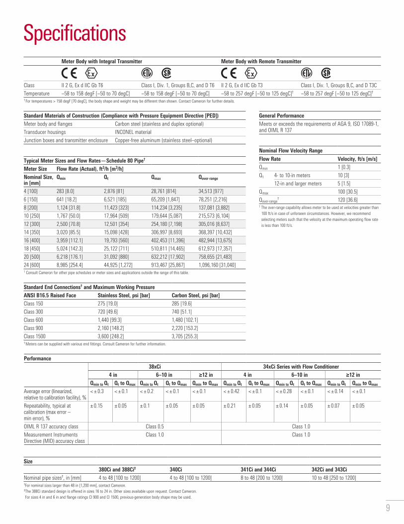
342CiThe 342Ci CALDON LEFM ultrasonic flowmeter retains all of the advantages of the four-path 340Ci model and incorporates a vertical reflective path for detecting the presence of moisture or contamination along the bottom of the pipe�
CALDON LEFM Flowmeter Models for Gases
343CiThe four-path, chordal-measurement 343Ci CALDON LEFM ultrasonic flowmeter combines both a secondary diametric single-path measurement for enhanced diagnostics and a vertical reflective path for detecting the presence of moisture or contamination along the bottom of the pipe�
344CiThe 344Ci CALDON LEFM ultrasonic flowmeter features two independent four-path flowmeters in one compact meter body� The four-path-plus-four-path design meets all custody-transfer requirements while offering full redundancy and meter-to-meter comparison for in situ validation�
7

CALDON USM Advisor Software Data FeaturesDiagnostics Data Fingerprint Data†
Gain Gain
Signal-to-noise ratio Signal-to-noise ratio
% acceptance of pulses
Speed of sound Speed of sound
Standard deviation (turbulence) Standard deviation (%) per path
Normalized path velocities Normalized path velocities
Flatness Flatness
Asymmetry Asymmetry
Swirl‡ Swirl‡
Plane balance‡ Plane balance‡
Output options include screen, historian, and reports.† Up to 11 variables, depending on meter configuration.‡ 8-path meters only.
Meter health status trend for multiple meters at the meter station hierarchy level.
Historical signal-to-noise ratio vs. velocity trend at Path View.
Multiple parameters for a single meter at Meter View.
CALDON USM Advisor condition-based monitoring (CBM) software helps reduce risks by monitoring for key parameters, changes in process conditions, and other factors that affect measurement uncertainty and data integrity in ultrasonic flowmeters� CALDON USM Advisor software enables operators to improve decision making by providing intelligent alarms and dynamically adjusted CBM thresholds based on real-time and historical data from CALDON* ultrasonic flowmeter products and flow conditions� The easy-to-use, icon-driven software records, displays, reports, and analyzes flowmeter data and compares operating conditions with a set of reference conditions to deliver intelligent insight into meter performance�
The CALDON USM Advisor Meter Explorer module enables users to clearly visualize meter location using a four-level hierarchy to replicate system structure� This enables high-level or deep-dive analysis� The simple-to-use interface also includes a meter-setup wizard and full meter backup and restore facilities�
Features ■ Compliance with international standards, including ISO 17089 ■ Real-time or time-period data ■ Alarms for meter hard errors, global CBM limits, and fingerprint limits ■ Multiple configurable fingerprint data groups ■ Multivariable time-based trending ■ Configurable meter hierarchy ■ Customizable customer logo on reports ■ Easy navigation to all connected meters ■ Meter configuration and setup wizard ■ Zoomable display and timeframes ■ Four role-based levels of access ■ User logon and password for data security
CALDON USM Advisor software
8
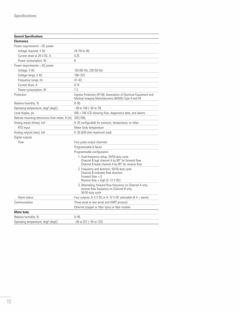
General PerformanceMeets or exceeds the requirements of AGA 9, ISO 17089-1, and OIML R 137
Nominal Flow Velocity Range
Flow Rate Velocity, ft/s [m/s]Qmin 1 [0.3]
Qt 4- to 10-in meters 10 [3]
12-in and larger meters 5 [1.5]
Qmax 100 [30.5]
Qover-range† 120 [36.6]
† The over-range capability allows meter to be used at velocities greater than 100 ft/s in case of unforseen circumstances. However, we recommend selecting meters such that the velocity at the maximum operating flow rate is less than 100 ft/s.
Standard End Connections† and Maximum Working PressureANSI B16.5 Raised Face Stainless Steel, psi [bar] Carbon Steel, psi [bar]Class 150 275 [19.0] 285 [19.6]
Class 300 720 [49.6] 740 [51.1]
Class 600 1,440 [99.3] 1,480 [102.1]
Class 900 2,160 [148.2] 2,220 [153.2]
Class 1500 3,600 [248.2] 3,705 [255.3] † Meters can be supplied with various end fittings. Consult Cameron for further information.
Meter Body with Integral Transmitter Meter Body with Remote Transmitter
Class II 2 G, Ex d IIC Gb T6 Class I, Div. 1, Groups B,C, and D T6 II 2 G, Ex d IIC Gb T3 Class I, Div. 1, Groups B,C, and D T3C
Temperature −58 to 158 degF [−50 to 70 degC] −58 to 158 degF [−50 to 70 degC] −58 to 257 degF [−50 to 125 degC]† −58 to 257 degF [−50 to 125 degC]†† For temperatures > 158 degF [70 degC], the body shape and weight may be different than shown. Contact Cameron for further details.
Standard Materials of Construction (Compliance with Pressure Equipment Directive [PED])Meter body and flanges Carbon steel (stainless and duplex optional)
Transducer housings INCONEL material
Junction boxes and transmitter enclosure Copper-free aluminum (stainless steel–optional)
Specifications
Performance38xCi 34xCi Series with Flow Conditioner
4 in 6–10 in ≥12 in 4 in 6–10 in ≥12 inQmin to Qt Qt to Qmax Qmin to Qt Qt to Qmax Qmin to Qmax Qmin to Qt Qt to Qmax Qmin to Qt Qt to Qmax Qmin to Qt Qmin to Qmax
Average error (linearized, relative to calibration facility), %
< ± 0.3 < ± 0.1 < ± 0.2 < ± 0.1 < ± 0.1 < ± 0.42 < ± 0.1 < ± 0.28 < ± 0.1 < ± 0.14 < ± 0.1
Repeatability, typical at calibration (max error – min error), %
± 0.15 ± 0.05 ± 0.1 ± 0.05 ± 0.05 ± 0.21 ± 0.05 ± 0.14 ± 0.05 ± 0.07 ± 0.05
OIML R 137 accuracy class Class 0.5 Class 1.0
Measurement Instruments Directive (MID) accuracy class
Class 1.0 Class 1.0
Size380Ci and 388Ci‡ 340Ci 341Ci and 344Ci 342Ci and 343Ci
Nominal pipe sizes†, in [mm] 4 to 48 [100 to 1200] 4 to 48 [100 to 1200] 8 to 48 [200 to 1200] 10 to 48 [250 to 1200]†For nominal sizes larger than 48 in [1,200 mm], contact Cameron. ‡The 388Ci standard design is offered in sizes 16 to 24 in. Other sizes available upon request. Contact Cameron.For sizes 4 in and 6 in and flange ratings Cl 900 and Cl 1500, previous-generation body shape may be used.
Typical Meter Sizes and Flow Rates—Schedule 80 Pipe†
Meter Size Flow Rate (Actual), ft3/h [m3/h]Nominal Size, in [mm]
Qmin Qt Qmax Qover-range
4 [100] 283 [8.0] 2,876 [81] 28,761 [814] 34,513 [977]
6 [150] 641 [18.2] 6,521 [185] 65,209 [1,847] 78,251 [2,216]
8 [200] 1,124 [31.8] 11,423 [323] 114,234 [3,235] 137,081 [3,882]
10 [250] 1,767 [50.0] 17,964 [509] 179,644 [5,087] 215,573 [6,104]
12 [300] 2,500 [70.8] 12,501 [354] 254,180 [7,198] 305,016 [8,637]
14 [350] 3,020 [85.5] 15,098 [428] 306,997 [8,693] 368,397 [10,432]
16 [400] 3,959 [112.1] 19,793 [560] 402,453 [11,396] 482,944 [13,675]
18 [450] 5,024 [142.3] 25,122 [711] 510,811 [14,465] 612,973 [17,357]
20 [500] 6,218 [176.1] 31,092 [880] 632,212 [17,902] 758,655 [21,483]
24 [600] 8,985 [254.4] 44,925 [1,272] 913,467 [25,867] 1,096,160 [31,040]† Consult Cameron for other pipe schedules or meter sizes and applications outside the range of this table.
9
Specifications
General SpecificationsElectronicsPower requirements—DC power
Voltage required, V DC 24 (18 to 30)
Current draw at 24 V DC, A 0.25
Power consumption, W 6
Power requirements—AC power
Voltage, V AC 120 (60 Hz); 230 (50 Hz)
Voltage range, V AC 108–253
Frequency range, Hz 47–63
Current draw, A 0.14
Power consumption, W 7.3
Protection Ingress Protection (IP) 66; Association of Electrical Equipment and Medical Imaging Manufacturers (NEMA) Type 4 and 4X
Relative humidity, % 0–95
Operating temperature, degF [degC] −58 to 158 [−50 to 70]
Local display, px 400 × 240 LCD showing flow, diagnostics data, and alarms
Remote mounting electronics from meter, ft [m] 328 [100]
Analog inputs (three), mA 4–20 configurable for pressure, temperature, or other
RTD input Meter body temperature
Analog outputs (two), mA 4–20 (650-ohm maximum load)
Digital outputs
Flow Four pulse output channels
Programmable K-factor
Programmable configuration
1. Dual-frequency setup, 50/50 duty cycle Channel B lags channel A by 90° for forward flow Channel B leads channel A by 90° for reverse flow
2. Frequency and direction, 50/50 duty cycle Channel B indicates flow direction Forward flow = 0 Reverse flow = high (5–12 V DC)
3. Alternating, forward-flow frequency on Channel A only; reverse-flow frequency on Channel B only; 50/50 duty cycle
Alarm status Four outputs, 0–5 V DC or 0–12 V DC selectable (0 V = alarm)
Communication
Three serial or two serial and HART protocol
Ethernet (copper or fiber optic) or fiber modem
Meter bodyRelative humidity, % 0–95
Operating temperature, degF [degC] −58 to 257 [−50 to 125]
10

Optional pressure port per AGA
Optional pressure port per AGA
Optional pressure port per AGA
Meter body with integral transmitter.
Optional pressure port per AGA.
Dimensions and Weights
W
H
L
Dimension and Weights for 340Ci, 341Ci, 342Ci, 343Ci, 344Ci, 380Ci, and 388Ci ModelsNominal Pipe Size, in [mm]
Applicable Model
Flange ANSI Class
Width (W), in [mm]
Height with Transmitter (H), in [mm]
Overall Length (L), in [mm] Weight with Components, lbm [kg]
Compact 3D Meter Compact 3D Meter
4 [100]
340Ci and 380Ci
150 13.9 [354] 19.1 [485] 16.8 [426] – 318.3 [144] –300 13.9 [354] 19.6 [498] 17.5 [445] – 759.7 [345] –600 10.7 [273] 22.7 [576] 19.3 [489] – 334.7 [152] –900 13.9 [354] 20.4 [517.1] 20.3 [514] – 402.8 [183] –1500 13.9 [354] 20.7 [526.5] 21.0 [533] – 437.6 [199] –
6 [150]
341Ci and 380Ci
150 11.0 [279] 20.5 [520] 18.5 [470] – 385.8 [175] –300 12.5 [318] 21.2 [539] 19.3 [489] – 440.9 [200] –600 14.0 [356] 22.0 [558] 21.3 [540] – 509.3 [231] –900 15.0 [381] 22.5 [571.0] 23.0 [584] – 586.4 [266] –1500 15.5 [394] 22.7 [577.0] 25.5 [648] – 734.1 [333] –
8 [200]
340Ci, 341Ci, 344Ci, and 380Ci
150 17.0 [432] 23.9 [606] 18.4 [467] 23.6 [600] 548.0 [249] 574.7 [261]300 17.0 [432] 24.4 [619] 19.1 [486] 23.6 [600] 604.6 [274] 627.5 [285]600 17.0 [432] 25.1 [638] 21.0 [533] 23.6 [600] 700.0 [317] 713.3 [324]900 18.5 [470] 25.5 [647.0] 25.7 [654] – 928.1 [421] –1500 19.0 [483] 25.7 [654.0] 29.8 [756] – 1,155.2 [524] –
10 [250]
340Ci, 341Ci, 342Ci, 343Ci, 344Ci, and 380Ci
150 20.0 [508] 28.2 [716] 19.4 [492] 29.5 [750] 852.4 [387] 931.8 [423]300 20.0 [508] 28.2 [716] 20.6 [524] 29.5 [750] 940.9 [427] 1,010.4 [458]600 20.0 [508] 28.7 [728] 23.5 [597] 29.5 [750] 1,128.3 [512] 1,175.4 [533]900 21.5 [546] 27.9 [708.0] 28.3 [718] 29.5 [750] 1,305.1 [592] 1,327.2 [602]1500 23.0 [584] 28.6 [727.0] 33.7 [857] 29.5 [750] 1,799.0 [816] 1,721.8 [781]
12 [300]
340Ci, 341Ci, 342Ci, 343Ci, 344Ci, and 380Ci
150 22.0 [559] 30.7 [779] 23.1 [587] 35.4 [900] 1,272.0 [577] 1,416.9 [643]300 22.0 [559] 30.7 [779] 24.4 [619] 35.4 [900] 1,389.0 [630] 1,519.1 [689]600 22.0 [559] 30.9 [785] 26.5 [673] 35.4 [900] 1,565.2 [710] 1,670.3 [758]900 24.0 [610] 30.4 [771.0] 30.5 [775] 35.4 [900] 1,754.9 [796] 1,858.5 [843]1500 26.5 [673] 31.6 [803.0] 37.0 [940] 35.4 [900] 2,605.9 [1,182] 2,568.4 [1,165]
14 [350]
340Ci, 341Ci, 342Ci, 343Ci, 344Ci, and 380Ci
150 23.8 [603] 31.9 [809] 25.1 [638] 41.3 [1,050] 1,592.2 [722] 1,813.6 [823]300 23.8 [603] 32.3 [820] 26.4 [670] 41.3 [1,050] 1,768.3 [802] 1,972.6 [895]600 23.8 [603] 32.6 [829] 28.3 [718] 41.3 [1,050] 1,916.9 [869] 2,095.6 [951]900 25.2 [641] 31.7 [806.0] 32.0 [813] 41.3 [1,050] 2,083.4 [945] 2,321.5 [1,053]1500 29.5 [749] 33.9 [860.0] 38.7 [984] 41.3 [1,050] 3,318.0 [1,505] 3,390.7 [1,538]
16 [400]
All 150 24.0 [610] 32.6 [828] 24.6 [625]† 47.2 [1,200] 1,481.3 [672]† 1,905.1 [864]300 25.5 [648] 33.6 [854] 26.1 [664]† 47.2 [1,200] 1,703.0 [772]† 2,098.6 [952]600 27.0 [686] 34.4 [873] 28.8 [730]† 47.2 [1,200] 1,979.3 [898]† 2,325.8 [1,055]900 27.8 [705] 34.3 [870.0] 33.3 [845]† 47.2 [1,200] 2,597.0 [1,178]† 3,024.7 [1,372]1500 32.5 [826] 36.6 [930.0] 40.7 [1,035]† 47.2 [1,200] 4,277.0 [1,940]† 4,504.0 [2,043]
18 [450]
All 150 26.0 [660] 34.5 [876] 26.1 [664]† 53.1 [1,350] 1,751.6 [795]† 2,359.6 [1,070]300 28.0 [711] 36.0 [914] 27.6 [702]† 53.1 [1,350] 2,052.6 [931]† 2,626.9 [1,192]600 29.3 [743] 36.6 [930] 29.8 [756]† 53.1 [1,350] 2,361.0 [1,071]† 2,887.5 [1,310]900 31.0 [787] 36.8 [935.0] 35.0 [889]† 53.1 [1,350] 3,364.3 [1,526]† 4,049.9 [1,837]1500 36.0 [914] 39.3 [998.0] 42.8 [1,086]† 53.1 [1,350] 5,496.1 [2,493]† 5,943.7 [2,696]
20 [500]
All 150 28.0 [711] 36.8 [935] 28.3 [718]† 59.1 [1,500] 2,192.5 [994]† 3,010.7 [1,366]300 30.5 [775] 38.3 [973] 29.6 [752]† 59.1 [1,500] 2,546.6 [1,155]† 3,328.2 [1,510]600 32.0 [813] 39.0 [992] 32.0 [813]† 59.1 [1,500] 2,961.2 [1,343]† 3,679.8 [1,669]900 33.7 [857] 39.2 [995.0] 37.5 [953]† 59.1 [1,500] 4,142.5 [1,879]† 5,088.3 [2,308]1500 38.7 [984] 41.7 [1,058.0] 46.0 [1,168]† 59.1 [1,500] 6,803.5 [3,086]† 7,464.8 [3,386]
24 [600]
All 150 32.0 [813] 40.9 [1,038] 31.1 [791]† 70.9 [1,800] 2,857.0 [1,296]† 4,273.8 [1,939]300 36.0 [914] 42.9 [1,089] 32.4 [822]† 70.9 [1,800] 3,401.1 [1,543]† 4,773.3 [2,165]600 37.0 [940] 43.4 [1,101] 35.3 [895]† 70.9 [1,800] 3,966.8 [1,799]† 5,236.6 [2,375]900 41.0 [1,041] 44.3 [1,125.0] 42.8 [1,086]† 70.9 [1,800] 6,552.1 [2,972]† 7,881.5 [3,575]1500 46.0 [1,168] 46.8 [1,189.0] 51.25 [1302]† 70.9 [1,800] 10,238.3 [4,644]† 11,318.5 [5,134]
†The 388Ci standard design is not available in the Compact length. Contact Cameron for other sizes.Consult Cameron for sizes larger than 24 in.
11
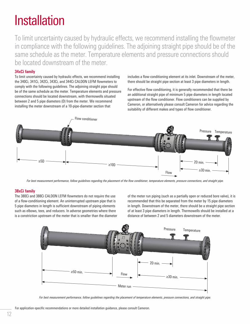
38xCi familyThe 380Ci and 388Ci CALDON LEFM flowmeters do not require the use of a flow-conditioning element� An uninterrupted upstream pipe that is 5 pipe diameters in length is sufficient downstream of piping elements such as elbows, tees, and reducers� In adverse geometries where there is a constriction upstream of the meter that is smaller than the diameter
of the meter run piping (such as a partially open or reduced bore valve), it is recommended that this be separated from the meter by 15 pipe diameters in length� Downstream of the meter, there should be a straight pipe section of at least 3 pipe diameters in length� Thermowells should be installed at a distance of between 2 and 5 diameters downstream of the meter�
To limit uncertainty caused by hydraulic effects, we recommend installing the flowmeter in compliance with the following guidelines. The adjoining straight pipe should be of the same schedule as the meter. Temperature elements and pressure connections should be located downstream of the meter.34xCi familyTo limit uncertainty caused by hydraulic effects, we recommend installing the 340Ci, 341Ci, 342Ci, 343Ci, and 344Ci CALDON LEFM flowmeters to comply with the following guidelines� The adjoining straight pipe should be of the same schedule as the meter� Temperature elements and pressure connections should be located downstream, with thermowells situated between 2 and 5 pipe diameters (D) from the meter� We recommend installing the meter downstream of a 10-pipe-diameter section that
includes a flow-conditioning element at its inlet� Downstream of the meter, there should be straight pipe section at least 3 pipe diameters in length�
For effective flow conditioning, it is generally recommended that there be an additional straight pipe of minimum 5 pipe diameters in length located upstream of the flow conditioner� Flow conditioners can be supplied by Cameron, or alternatively please consult Cameron for advice regarding the suitability of different makes and types of flow conditioner�
Installation
Flow
Pressure Temperature
≥5D min�≥3D min�
2D min�
Meter run
Flow conditioner
Pressure Temperature
≥5D≥10D
2D min�
≥3D min�Flow
For best measurement performance, follow guidelines regarding the placement of the flow conditioner, temperature elements, pressure connections, and straight pipe.
For best measurement performance, follow guidelines regarding the placement of temperature elements, pressure connections, and straight pipe.
For application-specific recommendations or more detailed installation guidance, please consult Cameron�
12

Notes
13
products.slb.com/caldon
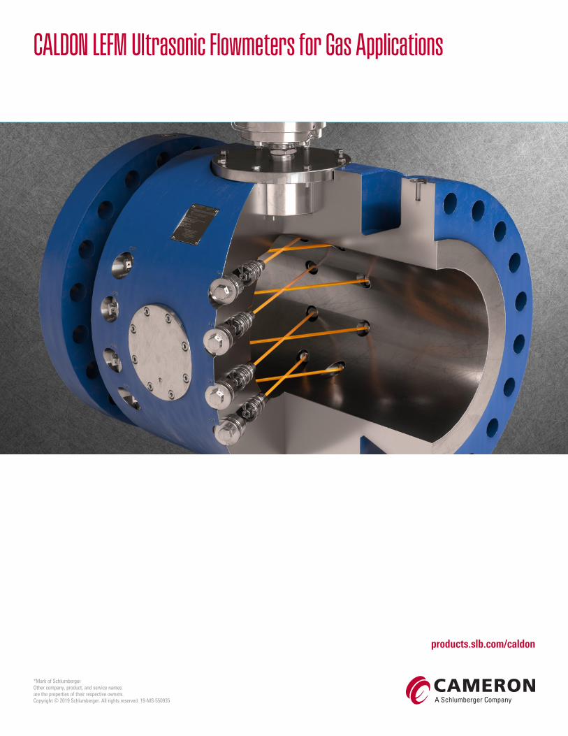
CALDON LEFM Ultrasonic Flowmeters for Gas Applications
*Mark of SchlumbergerOther company, product, and service names are the properties of their respective owners�Copyright © 2019 Schlumberger� All rights reserved� 19-MS-550935