Embed Size (px)
Citation preview

Engineering Calculation – FE021 Calculation Title:
Calculation for Load Capacity of Tubelock Beams
Calculation No.: CN-FE021-001 Rev. No.: 000
Plant/Project: Watts Bar Unit 2 Completion Project Prepared By: Kevin Wilson Date: 1/16/13
Checked By: N/A Date: N/A
Unit: All Building: All Elev.: All
Location: All
References: Item Ref. No. Description:
1 AISC Manual of Steel Construction, 8th Edition
2
3
4
5
6
7
8
9
10
Description of Calculation: Calculation for Load Capacity of Tubelock Beams with uniform load and load concentrated at the center.

Engineering Calculation – FE021 Calculation Title:
Calculation for Load Capacity of Tubelock Beams
Calculation No.: CN-FE021-001 Rev. No.: 000
Contents:
Section Description: Page No.
1.0 Calculation for Tubelock Properties
1.1 - Calculation of Properties of One Tubelock 1
1.2 - Calculation of Properties of Two Inline Tubelock 2
1.3 - Calculation of Properties of Three Inline Tubelock 3
1.4 - Calculation of Properties of Four Inline Tubelock 4
1.5 - Calculation of Properties of Three Triangle Tubelock 5
1.6 - Calculation of Properties of Four Square Tubelock 6
2.0 Calculation for loading on a beam supported at both ends
2.1 - Calculation Uniform Load Capacity of Beam 7
2.2 - Calculation Concentrated Load Capacity of Beam 8
Tables
Table 1a – Tubelock Data 9
Table 1b – Allowable Safety Factors (per 8th Edition AISC) 9
Table 1c – Allowable Stress 9
Table 2 – Section Property Data 9
Table 3 – Uniform Load Capacity of Tubelock Beams 11
Table 4 – Concentrated Load Capacity of Tubelock Beams 13
Attachments:
Attachment A – Atlantic Pacific Tubelock Data Sheet A1

Calculation Title: Calculation for Load Capacity of Tube Lock Beam
Engineering EvaluationWatts Bar Nuclear Plant
Unit #2 Completion Project
Calculation No.: CN-FE021-001
Section 1.0 - Calculate Section Properties of Tubelock:
Base Units: ksi 1000lb
in2⋅:= kip 1000 lb⋅:= psi 1
lb
in2⋅:=
Properties and Dimensions of the Tube Lock:
E 29000000psi:= Fy 50ksi:= Fu 70ksi:=
Outside Diameter of Tube Lock: OD 1.9in:=
Wall Thickness of Tube Lock: tTube 0.125in:=
Clamp Thickness: tC_2 2.0in:=
Clamp Thickness: tC_75 0.75in:=
Inside Diameter: ID OD tTube− tTube−:= ID 1.65 in=
__________________________________________________________________________________________________
Section 1.1 - Calculate Section Properties of One Tubelock:
Area of Section: A1 π OD tTube−( )⋅⎡⎣ ⎤⎦ tTube⋅:= A1 0.697 in2=
Shear Area: Av1 A1 0.6⋅:= Av1 0.418 in2=
Moment of Inertia: I1 0.049087 OD4 ID4−( )⋅:= I1 0.276 in4=
Section Modulus: S1 0.098175OD4 ID4−( )
OD⋅:= S1 0.29 in3=
Radius of Gyration: r1OD2 ID2+
4:= r1 0.629 in=
__________________________________________________________________________________________________
Capacity of Section (4:1 Safety Factor):
Shear Capacity: VCap1Fy Av1⋅( )4
:= VCap1 5.228 kip⋅=
Moment Capacity: MCap1Fy S1⋅( )4
:= MCap1 3.63 kip in⋅⋅=
Page 1 of 14

Calculation Title: Calculation for Load Capacity of Tube Lock Beam
Engineering EvaluationWatts Bar Nuclear Plant
Unit #2 Completion Project
Calculation No.: CN-FE021-001
Section 1.2 - Calculate Section Properties of Two Inline Tubelock:
Area of Section: A2 A1 2⋅:= A2 1.394 in2=
Shear Area: Av2 A2 0.6⋅:= Av2 0.836 in2=
Centroid:
X-Axis: C2xOD 2⋅( ) tC_2+⎡⎣ ⎤⎦
2:= C2x 2.9 in=
Y-Axis: C2yOD2
:= C2y 0.95 in=
Moment of Inertia:
X-Axis: I2x I1 A1OD2
tC_22
+⎛⎜⎝
⎞⎟⎠
2
⋅⎡⎢⎣
⎤⎥⎦
+⎡⎢⎣
⎤⎥⎦2⋅:= I2x 5.853 in4=
Y-Axis: I2y I1 2⋅:= I2y 0.552 in4=
Section Modulus:
X-Axis: S2xI2xC2x
:= S2x 2.018 in3=
Y-Axis: S2yI2yC2y
:= S2y 0.581 in3=
Radius of Gyration:
X-Axis: r2xI2xA2
:= r2x 2.049 in=
Y-Axis:r2y
I2yA2
:= r2y 0.629 in=
__________________________________________________________________________________________________
Capacity of Section (4:1 Safety Factor):
Shear Capacity: VCap2Fy Av2⋅( )4
:= VCap2 10.456 kip⋅=
Moment Capacity:
X-Axis: MCap2xFy S2x⋅( )4
:= MCap2x 25.227 kip in⋅⋅=
Y-Axis: MCap2yFy S2y⋅( )4
:= MCap2y 7.26 kip in⋅⋅=
Page 2 of 14

Calculation Title: Calculation for Load Capacity of Tube Lock Beam
Engineering EvaluationWatts Bar Nuclear Plant
Unit #2 Completion Project
Calculation No.: CN-FE021-001
Section 1.3 - Calculate Section Properties of Three Inline Tubelock:
Area of Section: A3 A1 3⋅:= A3 2.091 in2=
Shear Area: Av3 A3 0.6⋅:= Av3 1.255 in2=
Centroid:
X-Axis: C3xOD 3⋅( ) tC_2 2⋅( )+⎡⎣ ⎤⎦
2:= C3x 4.85 in=
Y-Axis: C3yOD2
:= C3y 0.95 in=
Moment of Inertia:
X-Axis: I3x I1 A1 tC_2 OD+( )2⋅⎡⎣
⎤⎦+⎡
⎣⎤⎦ 2⋅
⎡⎣
⎤⎦ I1+:= I3x 22.032 in4=
Y-Axis: I3y I1 3⋅:= I3y 0.828 in4=
Section Modulus:
S3xI3xC3x
:= S3x 4.543 in3=X-Axis:
Y-Axis: S3yI3yC3y
:= S3y 0.871 in3=
Radius of Gyration:
r3xI3xA3
:= r3x 3.246 in=X-Axis:
Y-Axis: r3yI3yA3
:= r3y 0.629 in=
__________________________________________________________________________________________________
Capacity of Section (4:1 Safety Factor):
Shear Capacity: VCap3Fy Av3⋅( )4
:= VCap3 15.683 kip⋅=
Moment Capacity:
X-Axis: MCap3xFy S3x⋅( )4
:= MCap3x 56.782 kip in⋅⋅=
Y-Axis: MCap3yFy S3y⋅( )4
:= MCap3y 10.89 kip in⋅⋅=
Page 3 of 14

Calculation Title: Calculation for Load Capacity of Tube Lock Beam
Engineering EvaluationWatts Bar Nuclear Plant
Unit #2 Completion Project
Calculation No.: CN-FE021-001
Section 1.4 - Calculate Section Properties of Four Inline Tubelock:
Area of Section: A4 A1 4⋅:= A4 2.788 in2=
Shear Area: Av4 A4 0.6⋅:= Av4 1.673 in2=
Centroid:
X-Axis: C4xOD 4⋅( ) tC_2 3⋅( )+⎡⎣ ⎤⎦
2:= C4x 6.8 in=
Y-Axis: C4yOD2
:= C4y 0.95 in=
Moment of Inertia:
X-Axis: I4x I1 A1OD tC_2+
2⎛⎜⎝
⎞⎟⎠
2
⋅⎡⎢⎣
⎤⎥⎦
+⎡⎢⎣
⎤⎥⎦
I1 A1OD 3⋅( ) tC_2 3⋅( )+
2⎡⎢⎣
⎤⎥⎦
2
⋅⎡⎢⎣
⎤⎥⎦
+⎡⎢⎣
⎤⎥⎦
+⎡⎢⎣
⎤⎥⎦2⋅:= I4x 54.113 in4=
Y-Axis: I4y I1 4⋅:= I4y 1.103 in4=
Section Modulus:
X-Axis: S4xI4xC4x
:= S4x 7.958 in3=
Y-Axis:S4y
I4yC4y
:= S4y 1.162 in3=
Radius of Gyration:
r4xI4xA4
:= r4x 4.405 in=X-Axis:
Y-Axis: r4yI4yA4
:= r4y 0.629 in=
__________________________________________________________________________________________________
Capacity of Section (4:1 Safety Factor):
Shear Capacity: VCap4Fy Av4⋅( )4
:= VCap4 20.911 kip⋅=
Moment Capacity:
X-Axis: MCap4xFy S4x⋅( )4
:= MCap4x 99.473 kip in⋅⋅=
Y-Axis: MCap4yFy S4y⋅( )4
:= MCap4y 14.52 kip in⋅⋅=
Page 4 of 14
Calculation Title: Calculation for Load Capacity of Tube Lock Beam
Engineering EvaluationWatts Bar Nuclear Plant
Unit #2 Completion Project
Calculation No.: CN-FE021-001
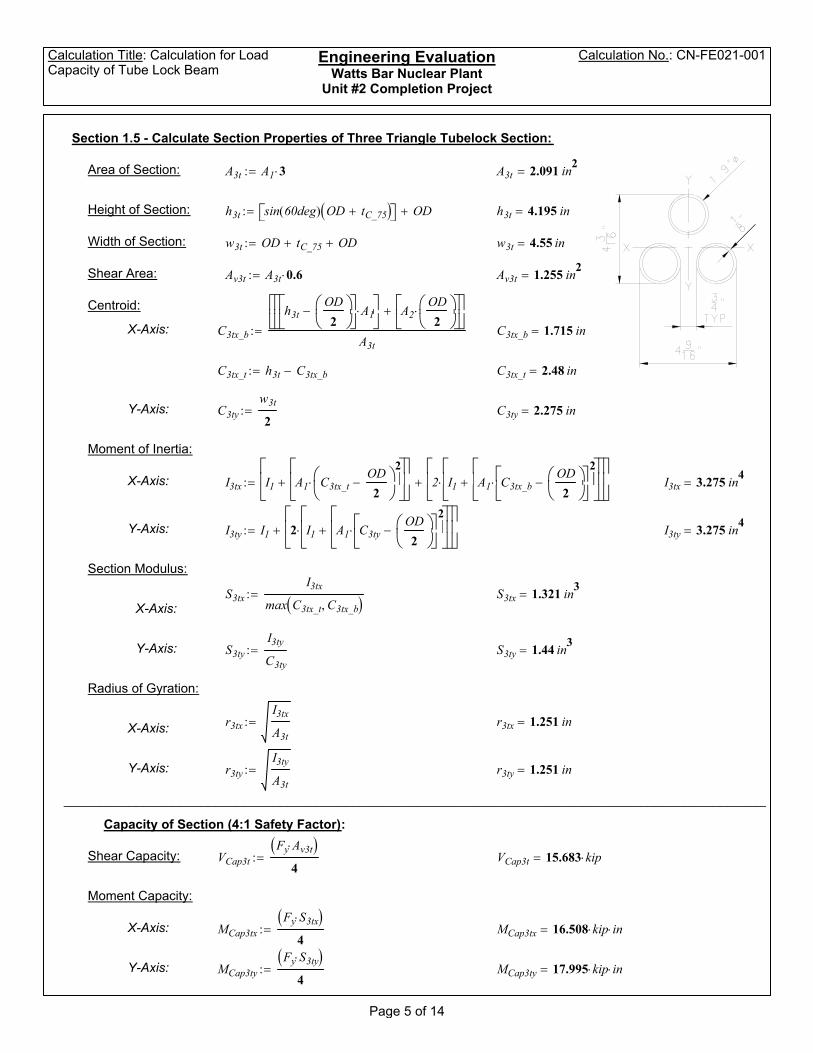
Section 1.5 - Calculate Section Properties of Three Triangle Tubelock Section:
Area of Section: A3t A1 3⋅:= A3t 2.091 in2=
Height of Section: h3t sin 60deg( ) OD tC_75+( )⎡⎣ ⎤⎦ OD+:= h3t 4.195 in=
Width of Section: w3t OD tC_75+ OD+:= w3t 4.55 in=
Shear Area: Av3t A3t 0.6⋅:= Av3t 1.255 in2=
Centroid:
X-Axis: C3tx_b
h3tOD2
⎛⎜⎝
⎞⎟⎠
−⎡⎢⎣
⎤⎥⎦A1⋅⎡⎢
⎣⎤⎥⎦
A2OD2
⎛⎜⎝
⎞⎟⎠
⋅⎡⎢⎣
⎤⎥⎦
+⎡⎢⎣
⎤⎥⎦
A3t:= C3tx_b 1.715 in=
C3tx_t h3t C3tx_b−:= C3tx_t 2.48 in=
Y-Axis: C3tyw3t2
:= C3ty 2.275 in=
Moment of Inertia:
X-Axis: I3tx I1 A1 C3tx_tOD2
−⎛⎜⎝
⎞⎟⎠
2⋅
⎡⎢⎣
⎤⎥⎦
+⎡⎢⎣
⎤⎥⎦
2 I1 A1 C3tx_bOD2
⎛⎜⎝
⎞⎟⎠
−⎡⎢⎣
⎤⎥⎦
2⋅
⎡⎢⎣
⎤⎥⎦
+⎡⎢⎣
⎤⎥⎦
⋅⎡⎢⎣
⎤⎥⎦
+:= I3tx 3.275 in4=
Y-Axis: I3ty I1 2 I1 A1 C3tyOD2
⎛⎜⎝
⎞⎟⎠
−⎡⎢⎣
⎤⎥⎦
2⋅
⎡⎢⎣
⎤⎥⎦
+⎡⎢⎣
⎤⎥⎦
⋅⎡⎢⎣
⎤⎥⎦
+:= I3ty 3.275 in4=
Section Modulus:
S3txI3tx
max C3tx_t C3tx_b, ( ):= S3tx 1.321 in3=X-Axis:
Y-Axis: S3tyI3tyC3ty
:= S3ty 1.44 in3=
Radius of Gyration:
r3txI3txA3t
:= r3tx 1.251 in=X-Axis:
Y-Axis: r3tyI3tyA3t
:= r3ty 1.251 in=
__________________________________________________________________________________________________
Capacity of Section (4:1 Safety Factor):
Shear Capacity: VCap3tFy Av3t⋅( )4
:= VCap3t 15.683 kip⋅=
Moment Capacity:
X-Axis: MCap3txFy S3tx⋅( )4
:= MCap3tx 16.508 kip in⋅⋅=
Y-Axis: MCap3tyFy S3ty⋅( )4
:= MCap3ty 17.995 kip in⋅⋅=
Page 5 of 14

Calculation Title: Calculation for Load Capacity of Tube Lock Beam
Engineering EvaluationWatts Bar Nuclear Plant
Unit #2 Completion Project
Calculation No.: CN-FE021-001
Section 1.6 - Calculate Section Properties of Four Square Tubelock:
Area of Section: A4s A1 4⋅:= A4s 2.788 in2=
Shear Area: Av4s A4s 0.6⋅:= Av4s 1.673 in2=
Centroid:
C4sxOD 2⋅( ) tC_75+⎡⎣ ⎤⎦
2:= C4sx 2.275 in=X-Axis:
Y-Axis: C4syOD 2⋅( ) tC_75+⎡⎣ ⎤⎦
2:= C4sy 2.275 in=
Moment of Inertia:
X-Axis: I4sx I1 A1 C4sxOD2
−⎛⎜⎝
⎞⎟⎠
2⋅
⎡⎢⎣
⎤⎥⎦
+⎡⎢⎣
⎤⎥⎦4⋅:= I4sx 5.998 in4=
Y-Axis: I4sy I1 A1 C4syOD2
−⎛⎜⎝
⎞⎟⎠
2⋅
⎡⎢⎣
⎤⎥⎦
+⎡⎢⎣
⎤⎥⎦4⋅:= I4sy 5.998 in4=
Section Modulus:
S4sxI4sxC4sx
:= S4sx 2.637 in3=X-Axis:
Y-Axis:S4sy
I4syC4sy
:= S4sy 2.637 in3=
Radius of Gyration:
r4sxI4sxA4s
:= r4sx 1.467 in=X-Axis:
Y-Axis: r4syI4syA4s
:= r4sy 1.467 in=
__________________________________________________________________________________________________
Capacity of Section (4:1 Safety Factor):
Shear Capacity: VCap4sFy Av4s⋅( )4
:= VCap4s 20.911 kip⋅=
Moment Capacity:
X-Axis: MCap4sxFy S4sx⋅( )4
:= MCap4sx 32.959 kip in⋅⋅=
Y-Axis: MCap4syFy S4sy⋅( )4
:= MCap4sy 32.959 kip in⋅⋅=
Page 6 of 14

Calculation Title: Calculation for Load Capacity of Tube Lock Beam
Engineering EvaluationWatts Bar Nuclear Plant
Unit #2 Completion Project
Calculation No.: CN-FE021-001
Section 2.0 - Calculation for Load Capacity of Tubelock Beam:
Base Units: ksi 1000lb
in2⋅:= kip 1000 lb⋅:= psi 1
lb
in2⋅:=
Properties and Dimensions of the Tube Lock:
E 29000000psi:= Fy 50ksi:= Fu 70ksi:=
Maximum Allowable Deflection: ΔMax 0.25in:=
Moment Capacity: MCap 25.228kip in⋅:= Moment of Inertia (X-Axis): Ix 5.853in4:=
Span of Tubelock Beam: L 8ft:=Shear Capacity: VCap 10.455kip:=
__________________________________________________________________________________________________
Section 2.1 - Check for Uniform Load Capacity:
The calculation below is used to calculate uniform load capacity for the Table 3.
Uniform Load Capacity based on shear:
wvVCap 2⋅( )L
2613.75lbft
⋅=:=
Uniform Load Capacity based on bending:
wbMCap 8⋅
L2262.792
lbft
⋅=:=
Uniform Load Capacity based on deflection:
wΔ
ΔMax 384⋅ E⋅ Ix⋅( )5 L4⋅
460.441lbft
⋅=:=
__________________________________________________________________________________________________
Uniform Load Capacity: wCap min wv wb, wΔ
, ( ) 262.792lbft
⋅=:=
Page 7 of 14

Calculation Title: Calculation for Load Capacity of Tube Lock Beam
Engineering EvaluationWatts Bar Nuclear Plant
Unit #2 Completion Project
Calculation No.: CN-FE021-001
Section 2.2 - Check for Concentrated Load Capacity:
The calculation below is used to calculate concentrated load capacity for the Table 4.
Concentrated Load Capacity based on shear:
Pv VCap 2⋅( ) 20910 lb⋅=:=
Concentrated Load Capacity based on bending:
PbMCap 4⋅
L1051.167 lb⋅=:=
Concentrated Load Capacity based on deflection:
PΔ
ΔMax 48⋅ E⋅ Ix⋅( )L3
2302.205 lb⋅=:=
__________________________________________________________________________________________________
Concentrated Load Capacity: PCap min Pv Pb, PΔ
, ( ) 1051.167 lb⋅=:=
Page 8 of 14

Section Properties Data for Tubelock Header and Beam Configurations
D = 1.900Tw = 0.125W = 2.5Fy = 50Fu = 70E = 29000
====== 0.375
fb = 12.5fv = 12.5ftg = 12.5ftn = 17.5fp = 12.5
ksi
ksi
Table 2 ‐ Section Property Data:
Allowable Tensile Stress (Net Area): ksi
ininlbs./lin. ft.ksiksi
Weight:
ksi
Table 1b ‐ Allowable Safety Factors (per 8th Edition AISC)
Table 1c ‐ Allowable Stresses
0.25
0.250.25
0.25
Allowable Tensile Stress (Gross Area):
Allowable Bearing:
Allowable Bearing Factor:
Allowable Shear Stress:
Allowable Bending Factor: Allowable ShearFactor:
Allowable Tension Factor (Gross Area):
Allowable Deflection:
Allowable Bending Stress:
Allowable Tension Factor (Net Area):
ksi
Table 1a ‐ Tubelock DataOutside Diameter:
Wall Thickness:
Yield Strength: Ultimate Strength:
Modulus of Elasticity:
0.25
in
ksi
X‐Axis Y‐Axis
Area: A = 0.697 0.697 in2
Effective Shear Area: Av = 0.418 0.418 in2
Centroid: C = 0.950 0.950 in
Moment of Inertia: I = 0.276 0.276 in4
Section Modulus: S = 0.290 0.290 in3
Radius of Gyration: r = 0.629 0.629 in
Maximum Shear (S.F. = 4:1): Vcap = 5.228 5.228 kips
Moment Capacity (S.F. = 4:1): Mcap = 3.625 3.625 in‐kip
Area: A = 1.394 1.394 in2
Effective Shear Area: Av = 0.836 0.836 in2
Centroid C = 2.900 0.950 in
Moment of Inertia: I = 5.853 0.552 in4
Section Modulus: S = 2.018 0.581 in3
Radius of Gyration: r = 2.049 0.629 in
Maximum Shear (S.F. = 4:1): Vcap = 10.455 10.455 kips
Moment Capacity (S.F. = 4:1): Mcap = 25.228 7.261 in‐kip
2 Tu
belock
1 Tu
belock
Page 9 of 14

Section Properties Data for Tubelock Header and Beam Configurations
X‐Axis Y‐Axis
Table 2 ‐ Section Property Data:
Area: A = 2.091 2.091 in2
Effective Shear Area: Av = 1.255 1.255 in2
Centroid: C = 4.850 0.950 in
Moment of Inertia: I = 22.032 0.828 in4
Section Modulus: S = 4.543 0.871 in3
Radius of Gyration: r = 3.246 0.629 in
Maximum Shear (S.F. = 4:1): Vcap = 15.683 15.683 kips
Moment Capacity (S.F. = 4:1): Mcap_1 = 56.784 10.889 in‐kip
Area: A = 2.788 2.788 in2
Effective Shear Area: Av = 1.673 1.673 in2
Centroid: C = 6.800 0.950 in
Moment of Inertia: I = 54.113 1.103 in4
Section Modulus: S = 7.958 1.161 in3
Radius of Gyration: r = 4.406 0.629 in
Maximum Shear (S.F. = 4:1): Vcap = 20.910 20.910 kips
Moment Capacity (S.F. = 4:1): Mcap_1 = 99.472 14.513 in‐kip
Area: A = 2.091 2.091 in2
3 Tube
lock (Inline)
4 Tube
lock (Inline)
Effective Shear Area: Av = 1.255 1.255 in2
Centroid: C = 2.480 2.275 in
Moment of Inertia: I = 3.275 3.275 in4
Section Modulus: S = 1.321 1.440 in3
Radius of Gyration: r = 1.251 1.251 in
Maximum Shear (S.F. = 4:1): Vcap = 15.683 15.683 kips
Moment Capacity (S.F. = 4:1): Mcap_1 = 16.507 17.995 in‐kip
Area: A = 2.788 2.788 in2
Effective Shear Area: Av = 1.673 1.673 in2
Centroid: C = 2.275 2.275 in
Moment of Inertia: I = 5.998 5.998 in4
Section Modulus: S = 2.636 2.636 in3
Radius of Gyration: r = 1.467 1.467 in
Maximum Shear (S.F. = 4:1): Vcap = 20.910 20.910 kips
Moment Capacity (S.F. = 4:1): Mcap_1 = 32.956 32.956 in‐kip
3 Tube
lock (T
riangle)
4 Tu
belock (Squ
are)
Page 10 of 14

Span(feet)
MomentCapacity(Kip‐in.)
Shear Capacity (Kip)
Uniform ShearLoad Capacity
(lbs./ft.)
Uniform Bending
Load Capacity(lbs./ft)
UniformLoad Capacity
(lbs./ft.)
2 3.625 5.228 5228.000 604.167 604.167
3 3.625 5.228 3485.333 268.519 268.519
4 3.625 5.228 2614.000 151.042 151.042
5 3.625 5.228 2091.200 96.667 96.667
6 3.625 5.228 1742.667 67.130 67.130
7 3.625 5.228 1493.714 49.320 37.040
8 3.625 5.228 1307.000 37.760 21.712
4 25.228 10.455 5227.500 1051.185 1051.185
5 25.228 10.455 4182.000 672.759 672.759
6 25.228 10.455 3485.000 467.193 467.193
7 25.228 10.455 2987.143 343.244 343.244
1455.221
785.492
Uniform Deflection
Load Capacity(lbs./ft.)
5558.333
1097.942
347.396
142.293
Table 3 ‐ Uniform Load Capacity of Tubelock Beams(Simply Supported Fixed at Each End) 4:1 SF
21.712
1 Tu
beLock Con
fig.
68.621
37.040
3017.547
7367.057
Inlin
e Co
nfig.
8 25.228 10.455 2613.750 262.796 262.796
9 25.228 10.455 2323.333 207.642 207.642
10 25.228 10.455 2091.000 168.190 168.190
12 25.228 10.455 1742.500 116.798 90.951
5 56.784 15.683 6273.200 1514.240 1514.240
6 56.784 15.683 5227.667 1051.556 1051.556
7 56.784 15.683 4480.857 772.571 772.571
8 56.784 15.863 3965.750 591.500 591.500
9 56.784 15.683 3485.111 467.358 467.358
10 56.784 15.683 3136.600 378.560 378.560
12 56.784 15.683 2613.833 262.889 262.889
14 56.784 15.683 2240.429 193.143 184.798
6 99.472 20.910 6970.000 1842.074 1842.074
7 99.472 20.910 5974.286 1353.361 1353.361
8 99.472 20.910 5227.500 1036.167 1036.167
9 99.472 20.910 4646.667 818.700 818.700
10 99.472 20.910 4182.000 663.147 663.147
12 99.472 20.910 3485.000 460.519 460.519
14 99.472 20.910 2987.143 338.340 338.340
16 99.472 20.910 2613.750 259.042 259.042
840.876
453.884
266.059
460.441
287.451
90.951
13454.021
4256.936
1743.641
1733.203
709.920
342.361
184.798
7262.145
1082.030
2657.584
3 Tu
beLock In
line Co
nfig.
5477.778
2 Tu
beLock I
2956.768
11358.720
188.597
4 Tu
beLock In
line Co
nfig.
Page 11 of 14

Span(feet)
MomentCapacity(Kip‐in.)
Shear Capacity (Kip)
Uniform ShearLoad Capacity
(lbs./ft.)
Uniform Bending
Load Capacity(lbs./ft)
UniformLoad Capacity
(lbs./ft.)
Uniform Deflection
Load Capacity(lbs./ft.)
Table 3 ‐ Uniform Load Capacity of Tubelock Beams(Simply Supported Fixed at Each End) 4:1 SF
4 16.507 15.683 7841.500 687.792 687.792
5 16.507 15.683 6273.200 440.187 440.187
6 16.507 15.683 5227.667 305.685 305.685
7 16.507 15.683 4480.857 224.585 224.585
8 16.507 15.683 3920.750 171.948 171.948
9 16.507 15.683 3485.111 135.860 135.860
10 16.507 15.683 3136.600 110.047 105.528
12 16.507 15.683 2613.833 76.421 50.891
14 16.507 15.683 2240.429 56.146 27.470
5 32.956 20.910 8364.000 878.827 878.827
6 32.956 20.910 6970.000 610.296 610.296
257.636
160.841
105.528
50.891
27.470
814.258
439.516
3 Tu
beLock Trian
gle Co
nfig.
onfig
. 3092.302
1491.272
4122.179
1688.444
7 32.956 20.910 5974.286 448.381 448.381
8 32.956 20.910 5227.500 343.292 343.292
9 32.956 20.910 4646.667 271.243 271.243
10 32.956 20.910 4182.000 219.707 193.269
12 32.956 20.910 3485.000 152.574 93.205
14 32.956 20.910 2987.143 112.095 50.3094 Tu
beLock Squ
are Co 804.952
471.848
294.572
193.269
93.205
50.309
Page 12 of 14

Span(feet)
MomentCapacity(Kip‐in.)
Shear Capacity (Kip)
Concentrated Shear
Load Capacity(lbs.)
Concentrated Bending
Load Capacity(lbs.)
ConcentratedLoad Capacity
(lbs.)
2 3.625 5.228 10456.000 604.167 604.167
3 3.625 5.228 10456.000 402.778 402.778
4 3.625 5.228 10456.000 302.083 302.083
5 3.625 5.228 10456.000 241.667 241.667
6 3.625 5.228 10456.000 201.389 201.389
7 3.625 5.228 10456.000 172.619 162.051
8 3.625 5.228 10456.000 151.042 108.561
4 25.228 10.455 20910.000 2102.371 2102.371
5 25.228 10.455 20910.000 1681.897 1681.897
6 25.228 10.455 20910.000 1401.580 1401.580
7 25.228 10.455 20910.000 1201.355 1201.355
Table 4 ‐ Concentrated Load Capacity of Tubelock Beams(Simply Supported Fixed at Each End) 4:1 SF
Concentrated Deflection
Load Capacity(lbs.)
1 Tu
beLock Con
fig.
6947.917
2058.642
868.490
444.667
257.330
162.051
108.561
Inlin
e Co
nfig. 18417.643
9429.833
5457.079
3436.528
8 25.228 10.455 20910.000 1051.185 1051.185
9 25.228 10.455 20910.000 934.387 934.387
10 25.228 10.455 20910.000 840.948 840.948
12 25.228 10.455 20910.000 700.790 682.135
5 56.784 15.683 31366.000 3785.600 3785.600
6 56.784 15.683 31366.000 3154.667 3154.667
7 56.784 15.683 31366.000 2704.000 2704.000
8 56.784 15.863 31726.000 2366.000 2366.000
9 56.784 15.683 31366.000 2103.111 2103.111
10 56.784 15.683 31366.000 1892.800 1892.800
12 56.784 15.683 31366.000 1577.333 1577.333
14 56.784 15.683 31366.000 1352.000 1352.000
6 99.472 20.910 41820.000 5526.222 5526.222
7 99.472 20.910 41820.000 4736.762 4736.762
8 99.472 20.910 41820.000 4144.667 4144.667
9 99.472 20.910 41820.000 3684.148 3684.148
10 99.472 20.910 41820.000 3315.733 3315.733
12 99.472 20.910 41820.000 2763.111 2763.111
14 99.472 20.910 41820.000 2368.381 2368.381
16 99.472 20.910 41820.000 2072.333 2072.333
2 Tu
beLock I
2302.205
1616.912
1178.729
682.135
3 Tu
beLock In
line Co
nfig. 35496.000
20541.667
12935.860
8666.016
6086.420
4437.000
2567.708
1616.983
4 Tu
beLock In
line Co
nfig. 50452.578
31771.886
21284.682
14948.912
10897.757
6306.572
3971.486
2660.585
Page 13 of 14

Span(feet)
MomentCapacity(Kip‐in.)
Shear Capacity (Kip)
Concentrated Shear
Load Capacity(lbs.)
Concentrated Bending
Load Capacity(lbs.)
ConcentratedLoad Capacity
(lbs.)
Table 4 ‐ Concentrated Load Capacity of Tubelock Beams(Simply Supported Fixed at Each End) 4:1 SF
Concentrated Deflection
Load Capacity(lbs.)
4 16.507 15.683 31366.000 1375.583 1375.583
5 16.507 15.683 31366.000 1100.467 1100.467
6 16.507 15.683 31366.000 917.056 917.056
7 16.507 15.683 31366.000 786.048 786.048
8 16.507 15.683 31366.000 687.792 687.792
9 16.507 15.683 31366.000 611.370 611.370
10 16.507 15.683 31366.000 550.233 550.233
12 16.507 15.683 31366.000 458.528 381.683
14 16.507 15.683 31366.000 393.024 240.360
5 32.956 20.910 41820.000 2197.067 2197.067
6 32.956 20.910 41820.000 1830.889 1830.889
5276.389
3053.466
1922.882
1288.181
904.731
659.549
5592.271
381.683
240.360
onfig
. 9663.444
3 Tu
beLock Trian
gle Co
nfig.
10305.447
7 32.956 20.910 41820.000 1569.333 1569.333
8 32.956 20.910 41820.000 1373.167 1373.167
9 32.956 20.910 41820.000 1220.593 1220.593
10 32.956 20.910 41820.000 1098.533 1098.533
12 32.956 20.910 41820.000 915.444 699.034
14 32.956 20.910 41820.000 784.667 440.208
3521.663
2359.239
1656.969
1207.931
699.034
440.2084 Tu
beLock Squ
are Co
Page 14 of 14

TUBE AND CLAMP
*custom sizes available upon request
Steel Tube with Fittings
DESCRIPTION WEIGHT
4’ Tube with End Fitting 9.8 lbs
6’ Tube with End Fitting 13 lbs
8’ Tube with End Fitting 17 lbs
10’ Tube with End Fitting 21 lbs
13’ Tube with End Fitting 25 lbs
Engineering Specifications
Availableinhot-dipgalvanizedorblack49 mm (1.9”) outside diameter by 3.18 mm (0.125”) wall
Outside Diameter 49 mm 1.90 in
Wall Thickness 3.18 mm .125 in
Yield Strength 345 mpa 50,000 psi
Ultimate Strength 483 mpa 70,000 psi
Area 451 mm2 .699 in2
Moment of Inertia 115296 mm4 .277 in4
Section Modulus 4768 mm3 .291 in3
Radius of Gyration 16 mm .630 in
Bolt Clamps-Dual Purpose
RightAngle3.5 lbs
BeamClamp3.15 lbs
Swivel3.5 lbs
•DropforgedclampsavailableinI-BoltorT-Bolt
AT
LA
NT
IC P
AC
IFIC
EQ
UIP
AT
LA
NT
IC P
AC
IFIC
EQ
UIP
ME
NT
ME
NT

TUBE AND CLAMP
WWW.AT-PAC.COM1.800.263.0444 1�*custom sizes available upon request
Wedge Clamps
RIGHT ANGLE CLAMPTube Size: 1.69” O.D.
1.90” O.D.
2.375” O.D.
SWIVEL CLAMPTube Size: 1.69” O.D.
1.90” O.D.
2.375” O.D.
In addition 1.90” / 1.625”Center pin shear load 6,000 lbs
TEST RESULTS FOR 1.90” X 1.90” CLAMP
Right Angle: 2,500 lbs @ 4:1 S.F.
Swivel: 1.500 lbs @ 4:1 S.F.
•Wedgetravel:approximately3/4lengthofwedge
•Galvanized finish•No loose parts to lose or drop•Quickintsallanddismantle•Theonlytoolneededisahammer•Littleornomaintenancerequired
NOTE:•Userightanglecouplersonprimaryload
bearing members, such as vertical orhorizontalmembers
•Useswivelcouplersonsecondarynonload bearing members, such as diagonalbracingmembers
Engineering Specifications
DESCRIPTION SIZE WEIGHT:metric WEIGHT:imperial
RAClamp(tubetotube) 2” x 2” 1.45 kg 3.3 lbsSWClamp(tubetotube) 2” x 2” 1.45 kg 3.3 lbsRAClamp(tubetoframe) 2” x 1.625” 1.45 kg 3.3 lbsSWClamp(tubetoframe) 2” x 1.625” 1.45 kg 3.3 lbsRAClamp(frametoframe) 1.625” x 1.625” 1.45 kg 3.3 lbsSWClamp(frametoframe) 1.625” x 1.625” 1.45 kg 3.3 lbs
HalfSWWedgeClamp allsizes allsizes allsizes
JoinerClamp 2” x 2” 1.45 kg 3.3 lbs
RightAngleClamp SwivelClamp End-to-End Joiner

TUBE AND CLAMP
*custom sizes available upon request
Aluminum Scaffold Tube
DESCRIPTION SIZE WEIGHT
metric imperial metric imperialAluminumTube .61 m 2’ .82 kg 1.8 lbs
AluminumTube 1.22 m 4’ 1.64 kg 3.6 lbs
AluminumTube 1.52 m 5’ 2.05 kg 4.5 lbs
AluminumTube 1.83 m 6’ 2.46 kg 5.4 lbs
AluminumTube 2.13 m 7’ 2.86 kg 6.3 lbs
AluminumTube 2.44 m 8’ 3.27 kg 7.2 lbs
AluminumTube 3.05 m 10’ 4.09 kg 9lbs
AluminumTube 3.66 m 12’ 4.91 kg 10.8 lbs
AluminumTube 4.27 m 14’ 5.73 kg 12.6 lbs
AluminumTube 4.57 m 15’ 6.14 kg 13.5 lbs
AluminumTube 4.88 m 16’ 6.55 kg 14.4 lbs
AluminumTube 5.49 m 18’ 7.36 kg 16.2 lbs
AluminumTube 6.10 m 20’ 8.18 kg 18lbs
Available in 49mm (1.9”) outside diameter or by 37mm (schedule 40) wall
SCHEDULE 40 SPEFICATIONS
Outside Diameter 49 mm 1.90 inWall Thickness 3.7 mm .145 inYield Strength 255 mpa 37,000 psiUltimate Strength 300 mpa 44,000 psiArea 515 mm2 .799 in2
MomentofInertia 12931mm4 .310 in4
Section Modulus 5342 mm3 .326 in3
Radius of Gyration 15.82 mm .623 in
Engineering Specifications
AT
LA
NT
IC P
AC
IFIC
EQ
UIP
AT
LA
NT
IC P
AC
IFIC
EQ
UIP
ME
NT
ME
NT


