Embed Size (px)
Citation preview
Calculation of the Stress intensity factor with CINT command in 2D Workbench 13.0
Aalborg Universitet esbjerg Søren Heide Lambertsen
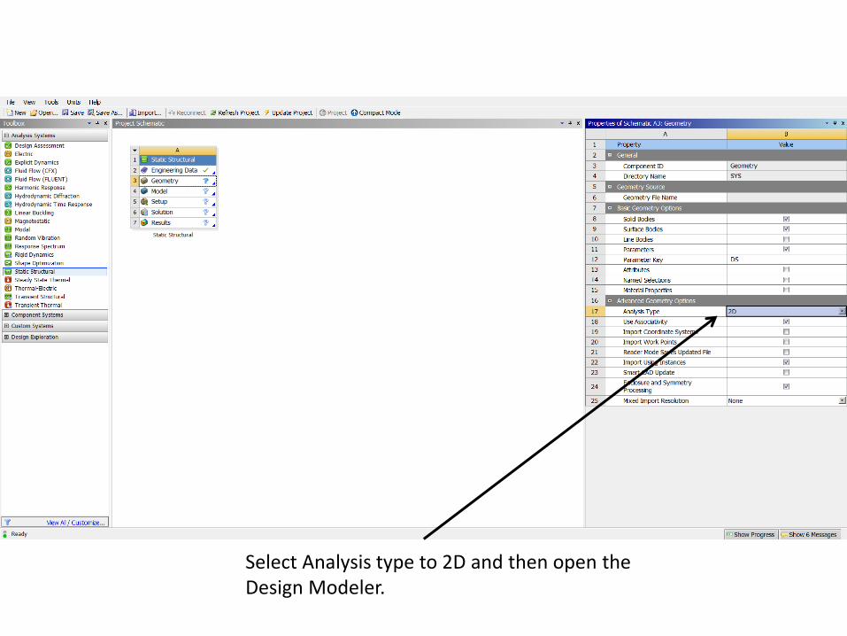
Select Analysis type to 2D and then open the Design Modeler.
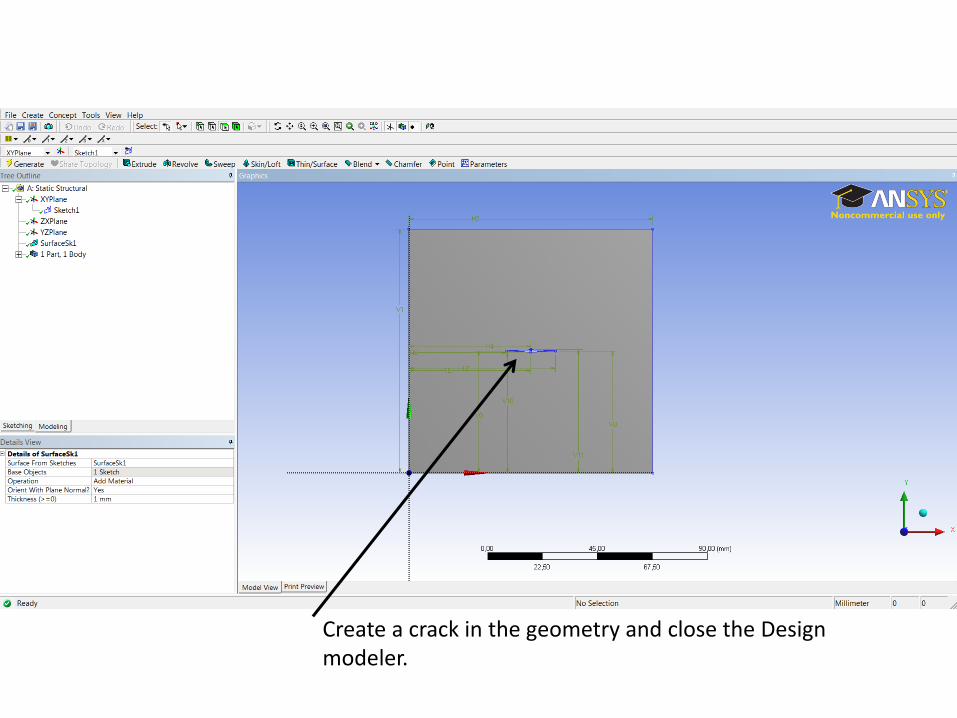
Create a crack in the geometry and close the Design modeler.
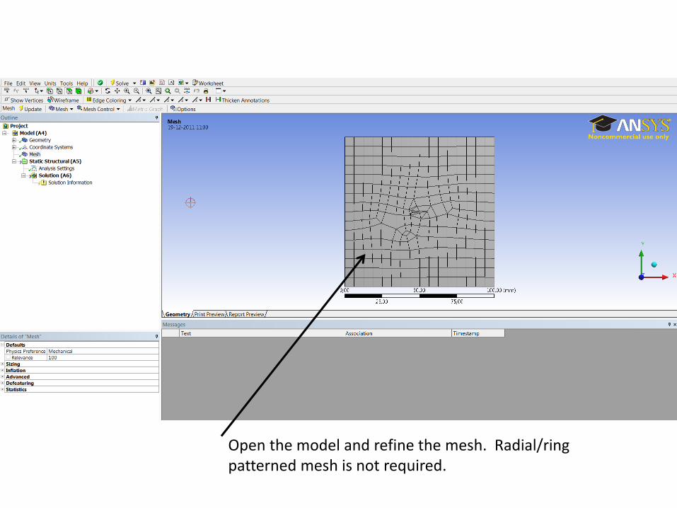
Open the model and refine the mesh. Radial/ring patterned mesh is not required.
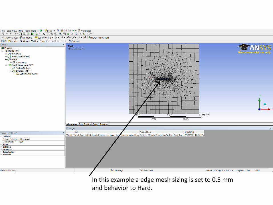
In this example a edge mesh sizing is set to 0,5 mm and behavior to Hard.
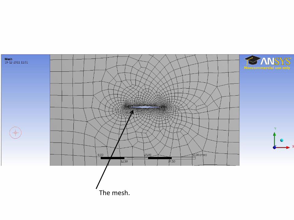
The mesh.
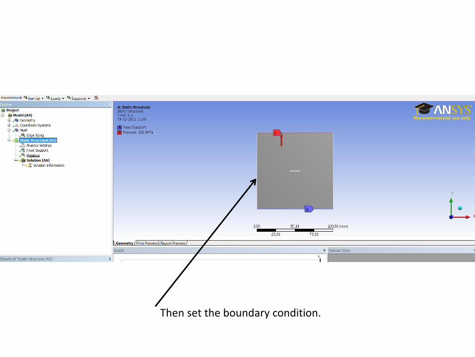
Then set the boundary condition.
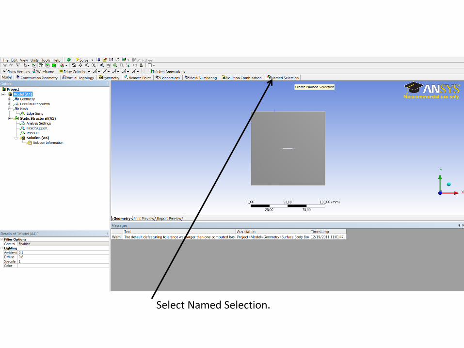
Select Named Selection.
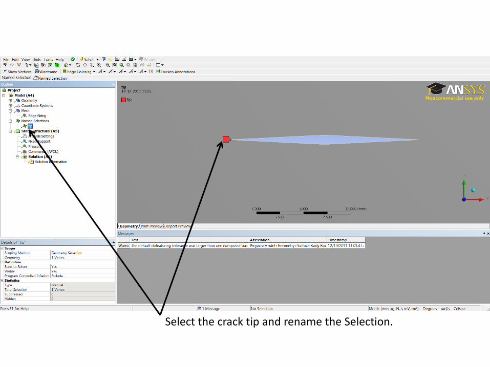
Select the crack tip and rename the Selection.
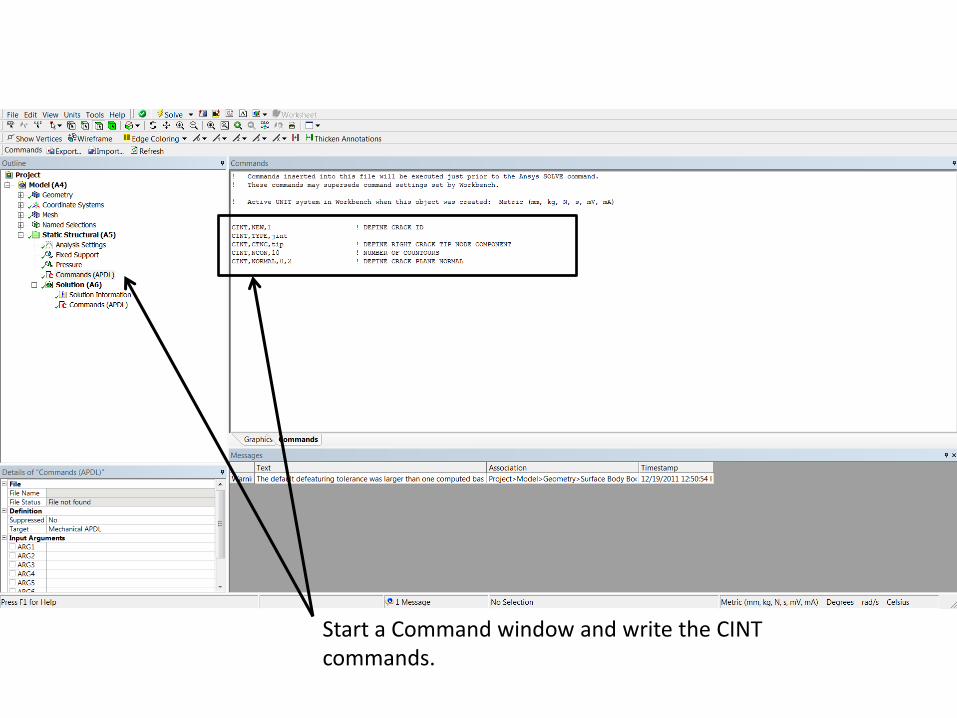
Start a Command window and write the CINT commands.

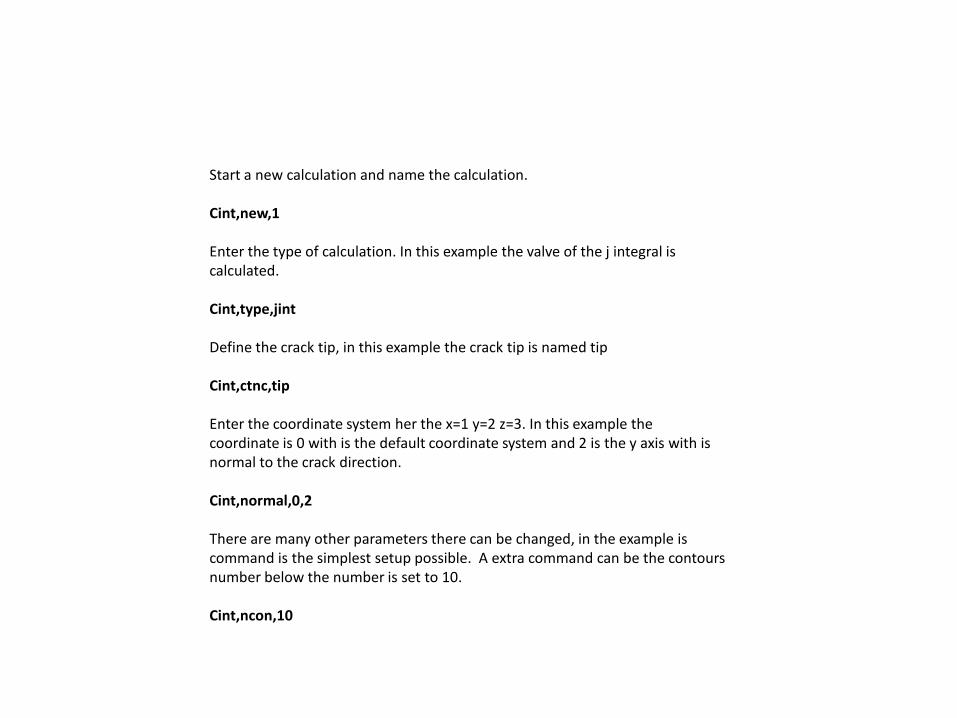
Start a new calculation and name the calculation. Cint,new,1 Enter the type of calculation. In this example the valve of the j integral is calculated. Cint,type,jint Define the crack tip, in this example the crack tip is named tip Cint,ctnc,tip Enter the coordinate system her the x=1 y=2 z=3. In this example the coordinate is 0 with is the default coordinate system and 2 is the y axis with is normal to the crack direction. Cint,normal,0,2 There are many other parameters there can be changed, in the example is command is the simplest setup possible. A extra command can be the contours number below the number is set to 10. Cint,ncon,10
Start a new calculation and name the calculation. Cint,new,1 Enter the type of calculation. In this example the valve of the j integral is calculated. Cint,type,jint Define the crack tip, in this example the crack tip is named tip Cint,ctnc,tip Enter the coordinate system her the x=1 y=2 z=3. In this example the coordinate is 0 with is the default coordinate system and 2 is the y axis with is normal to the crack direction. Cint,normal,0,2 There are many other parameters there can be changed, in the example is command is the simplest setup possible. A extra command can be the contours number below the number is set to 10. Cint,ncon,10
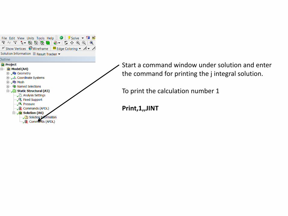
Start a command window under solution and enter the command for printing the j integral solution. To print the calculation number 1 Print,1,,JINT
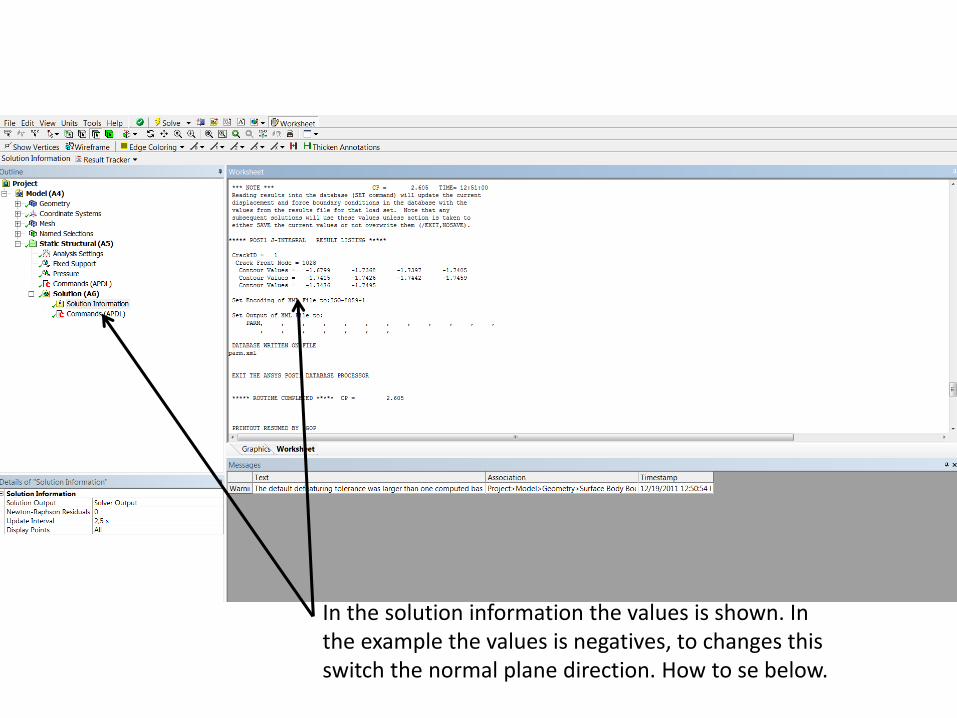
In the solution information the values is shown. In the example the values is negatives, to changes this switch the normal plane direction. How to se below.
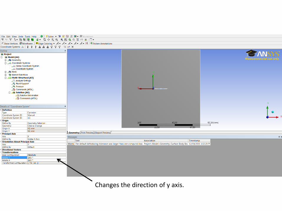
Changes the direction of y axis.
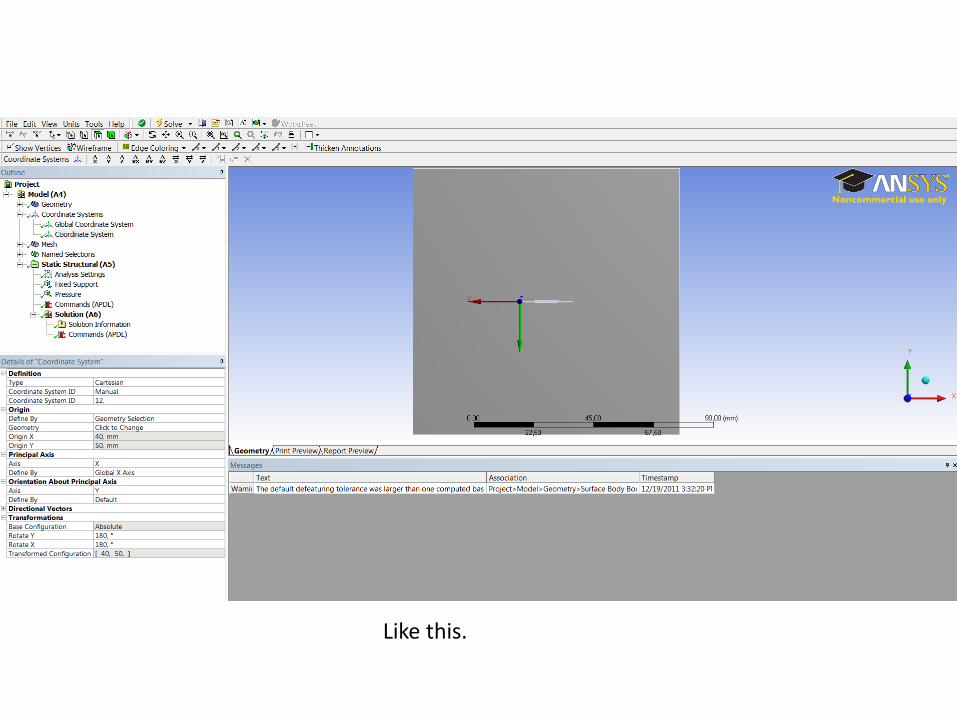
Like this.
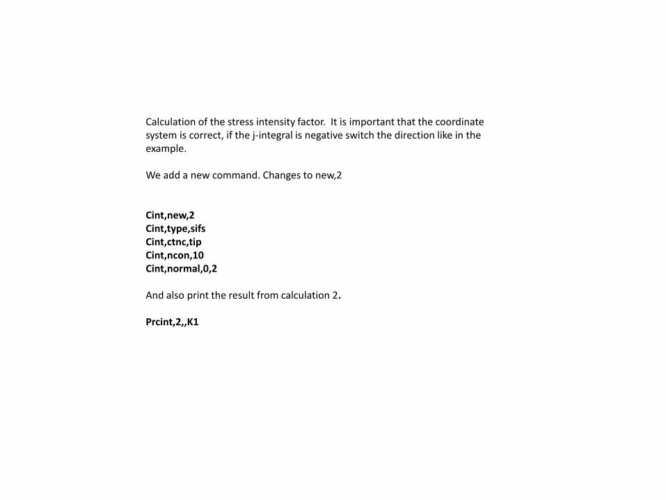
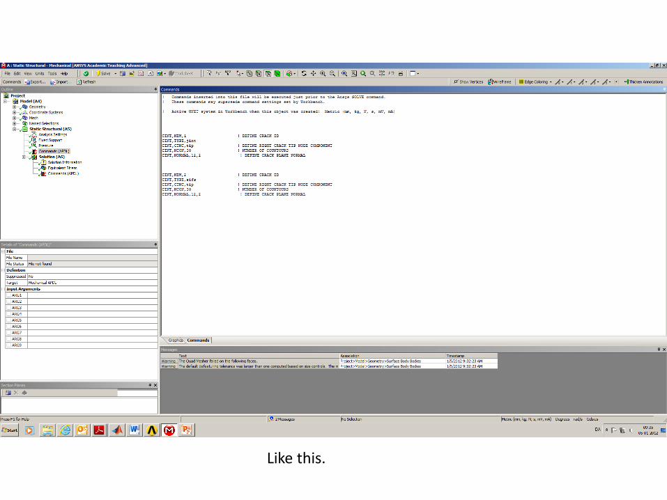
Calculation of the stress intensity factor. It is important that the coordinate system is correct, if the j-integral is negative switch the direction like in the example. We add a new command. Changes to new,2 Cint,new,2 Cint,type,sifs Cint,ctnc,tip Cint,ncon,10 Cint,normal,0,2 And also print the result from calculation 2. Prcint,2,,K1
Like this.
Like this.
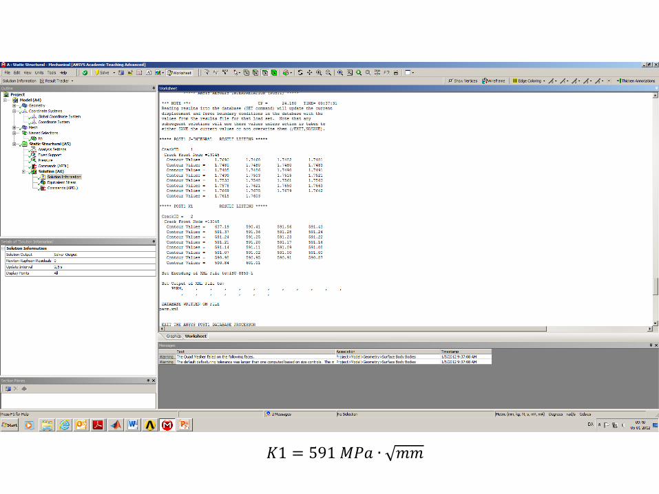
𝐾1 = 591 𝑀𝑃𝑎 ∙ 𝑚𝑚
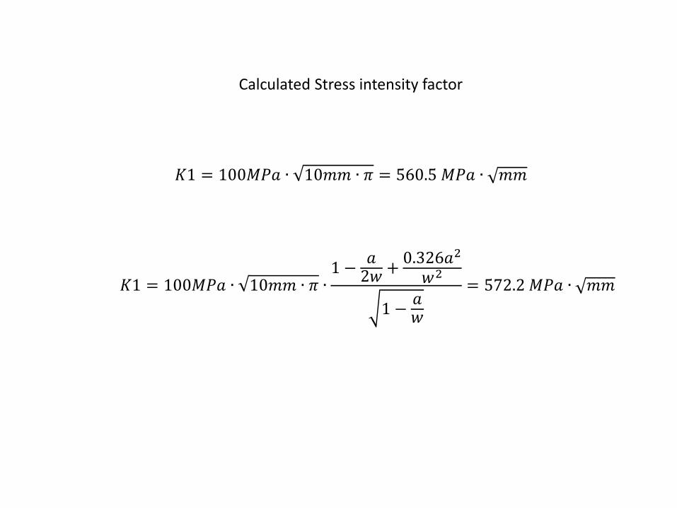
𝐾1 = 100𝑀𝑃𝑎 ∙ 10𝑚𝑚 ∙ 𝜋 = 560.5 𝑀𝑃𝑎 ∙ 𝑚𝑚
𝐾1 = 100𝑀𝑃𝑎 ∙ 10𝑚𝑚 ∙ 𝜋 ∙1 −
𝑎2𝑤
+0.326𝑎2
𝑤2
1 −𝑎𝑤
= 572.2 𝑀𝑃𝑎 ∙ 𝑚𝑚
Calculated Stress intensity factor