Embed Size (px)
Citation preview


1 H
HmHrn
•.<
... j
X
/'.<•«'
V*°*EAV O*
XIf) NBS TECHNICAL NOTE 657
U.S. DEPARTMENT OF COMMERCE/ National Bureau of Standards
Calculated and Measured S n , S21
,
and Group Delay for Simple Types of
Coaxial and Rectangular Waveguide
2-Port Standards

NATIONAL BUREAU OF STANDARDS
The National Bureau of Standards' was established by an act of Congress March 3, 1901.
The Bureau's overall goal is to strengthen and advance the Nation's science and technology
and facilitate their effective application for public benefit. To this end, the Bureau conducts
research and provides: (1) a basis for the Nation's physical measurement system, (2) scientific
and technological services for industry and government, (3) a technical basis for equity in trade,
and (4) technical services to promote public safety. The Bureau consists of the Institute for
Basic Standards, the Institute for Materials Research, the Institute for Applied Technology,
the Institute for Computer Sciences and Technology, and the Office for Information Programs.
THE INSTITUTE FOR BASIC STANDARDS provides the central basis within the United
States of a complete and consistent system of physical measurement; coordinates that system
with measurement systems of other nations; and furnishes essential services leading to accurate
and uniform physical measurements throughout the Nation's scientific community, industry,
and commerce. The Institute consists of a Center for Radiation Research, an Office of Meas-
urement Services and the following divisions:
Applied Mathematics — Electricity — Mechanics — Heat — Optical Physics — Nuclear
Sciences ' — Applied Radiation * — Quantum Electronics a — Electromagnetics * — Timeand Frequency ' — Laboratory Astrophysics a — Cryogenics *.
THE INSTITUTE FOR MATERIALS RESEARCH conducts materials research leading to
improved methods of measurement, standards, and data on the properties of well-characterized
materials needed by industry, commerce, educational institutions, and Government; provides
advisory and research services to other Government agencies; and develops, produces, and
distributes standard reference materials. The Institute consists of the Office of Standard
Reference Materials and the following divisions:
Analytical Chemistry — Polymers — Metallurgy — Inorganic Materials — Reactor
Radiation — Physical Chemistry.
THE INSTITUTE FOR APPLIED TECHNOLOGY provides technical services to promote
the use of available technology and to facilitate technological innovation in industry and
Government; cooperates with public and private organizations leading to the development of
technological standards (including mandatory safety standards), codes and methods of test;
and provides technical advice and services to Government agencies upon request. The Institute
consists of a Center for Building Technology and the following divisions and offices:
Engineering and Product Standards — Weights and Measures — Invention and Innova-
tion — Product Evaluation Technology — Electronic Technology — Technical Analysis
— Measurement Engineering — Structures, Materials, and Life Safety 4 — Building
Environment * — Technical Evaluation and Application * — Fire Technology.
THE INSTITUTE FOR COMPUTER SCIENCES AND TECHNOLOGY conducts research
and provides technical services designed to aid Government agencies in improving cost effec-
tiveness in the conduct of their programs through the selection, acquisition, and effective
utilization of automatic data processing equipment; and serves as the principal focus within
the executive branch for the development of Federal standards for automatic data processing
equipment, techniques, and computer languages. The Institute consists of the following
divisions:
Computer Services — Systems and Software — Computer Systems Engineering — Informa-
tion Technology.
THE OFFICE FOR INFORMATION PROGRAMS promotes optimum dissemination and
accessibility of scientific information generated within NBS and other agencies of the Federal
Government; promotes the development of the National Standard Reference Data System and
a system of information analysis centers dealing with the broader aspects of the National
Measurement System; provides appropriate services to ensure that the NBS staff has optimum
accessibility to the scientific information of the world. The Office consists of the following
organizational units:
Office of Standard Reference Data — Office of Information Activities — Office of Technical
Publications — Library — Office of International Relations.
Headquarters and Laboratories at Gaithersburg, Maryland, unless otherwise noted: mailing addressWashington, DC. 20234.
3 Part of the Center for Radiation Research.3 Located at Boulder, Colorado 80302.Part of the Center for Building Technology.
;'
fJOARDS
r
11' 2V
and Group Delay for Simple Types of
Coaxial and Rectangular Waveguide 2-Port Standards
R. W. Beatty
Electromagnetics Division
Institute for Basic Standards
(^ rS, National Bureau of Standards
Boulder, Colorado 80302
-t,leaU^itLai fls-hs. no
,k^>7
.t-" <"
l \ Jo
U.S. DEPARTMENT OF COMMERCE, Frederick B. Dent, Secretary
NATIONAL BUREAU OF STANDARDS Richard W Roberts Director
Issued December 1974
Library of Congress Catalog Card Number: 74-600191
National Bureau of Standards Technical Note 657
Nat. Bur. Stand. (U.S.), Tech Note 657, 67pages (Dec. 1974)
CODEN: NBTNAE
For sale by the Superintendent of Documents, U.S. Government Printing Office, Washington, D.C. 20402
(Order by SD Catalog No. C13. 46:657) $1.25
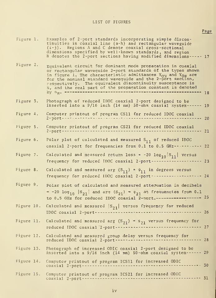
CONTENTS
Page
1. INTRODUCTION 1
2. FORMULAS FOR CALCULATION 2
3. COMPUTER PROGRAMS 3
4. EXAMPLES OF CALCULATED AND MEASURED DATA 4
4.1 Reduced IDOC Coaxial 2-Port 4
4.2 Increased ODIC Coaxial 2-Port 4
4.3 Reduced Height Rectangular Waveguide 2-Port 4
4 . 4 Discussion 5
5- DISCUSSION OF ERRORS 6
6. DESIGN INFORMATION 8
7. CONCLUSION 9
8 . ACKNOWLEDGMENTS 9
9. APPENDIX 9
10 . REFERENCES 11
APPENDIX : 5 3
LIST OF TABLES
Page
Table I. Additional parameters used in calculating S1
, , S21
, and Tr
of rectangular waveguide and coaxial line 2-ports 12
Table II. Reduced height hR
versus magnitude of S,1
for quarter-guide
wavelength WR90 (R-100) rectangular waveguide 2-ports 13
Table III. Increased ODIC and reduced IDOC versus |S11 |
for 9/16 inch
(14 mm) quarter-wavelength coaxial 2-ports 14
Table IV. Increased ODIC and reduced IDOC versus | St -iJ
for 7 mm
quarter-wavelength coaxial 2-ports 15
Table V. Approximate step capacitances versus |S,,| for quarter
wavelength 7 mm and 9/16 inch (14 mm) coaxial 2-ports usingeither increased ODIC or decreased IDOC 16
in
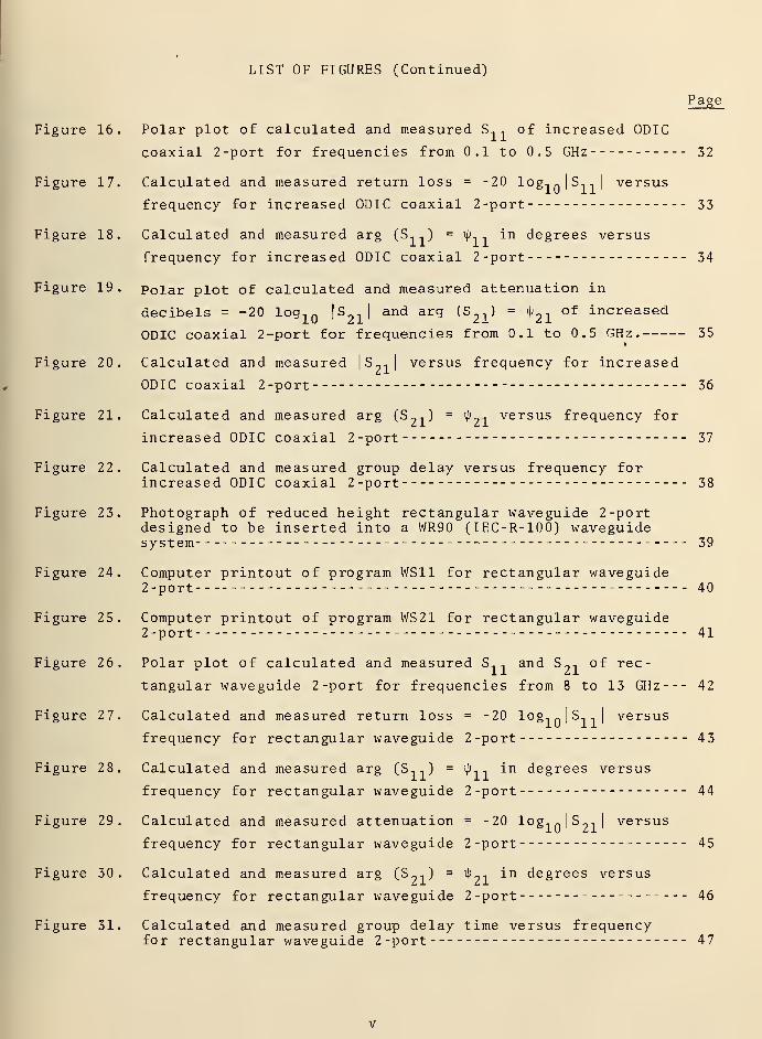
LIST OF FIGURES
Page
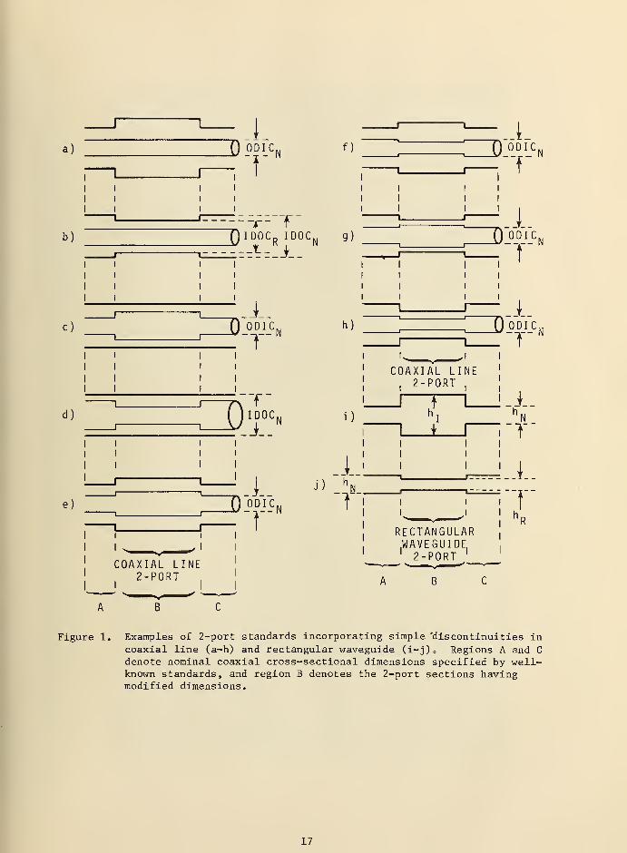
Figure 1. Examples of 2-port standards incorporating simple discon-tinuities in coaxial line (a-h) and rectangular waveguide(i-j). Regions A and C denote coaxial cross -sectionaldimensions specified by well-known standards, and regionB denotes the 2-port sections having modified dimensions 17
Figure 2. Equivalent circuit for dominant node propagation in coaxialor rectangular waveguide 2-port standards of the types shownin figure 1. The characteristic admittances YQN and YQ^ arefor the nominal standard waveguide and the 2-port section,respectively. The equivalent discontinuity susceptance is
B, and the real part of the propagation constant is denotedby a R . 18
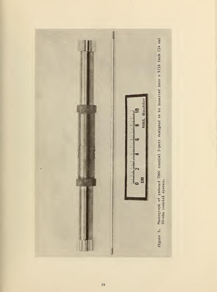
Figure 3. Photograph of reduced IDOC coaxial 2-port designed to beinserted into a 9/16 inch (14 mm) 50-ohm coaxial system 19
Figure 4. Computer printout of program CS11 for reduced IDOC coaxial2-port 20
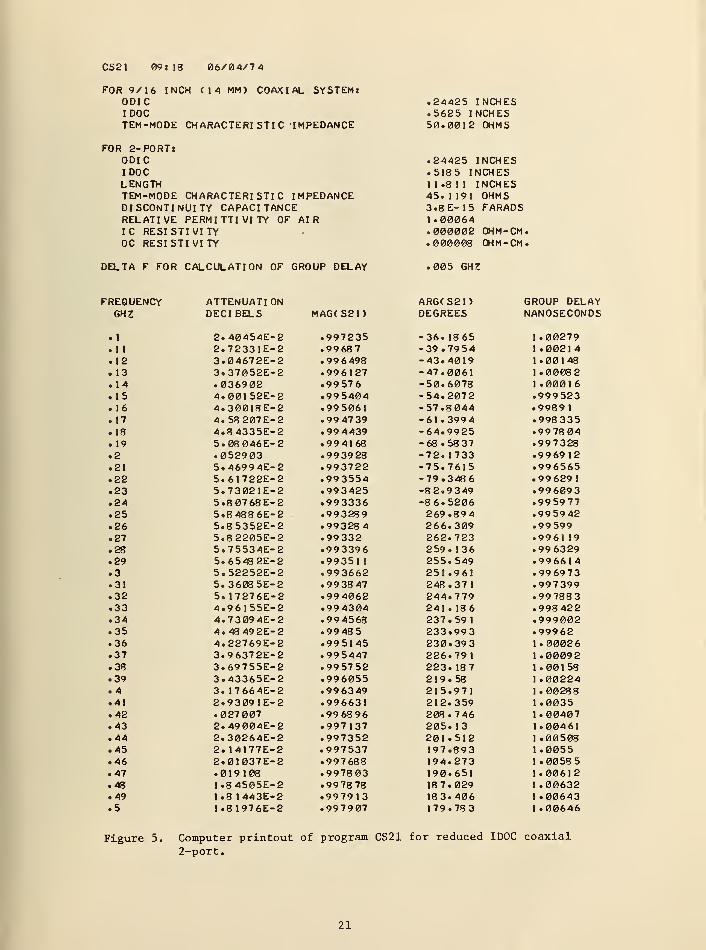
Figure 5. Computer printout of program CS21 for reduced IDOC coaxial2-port 21
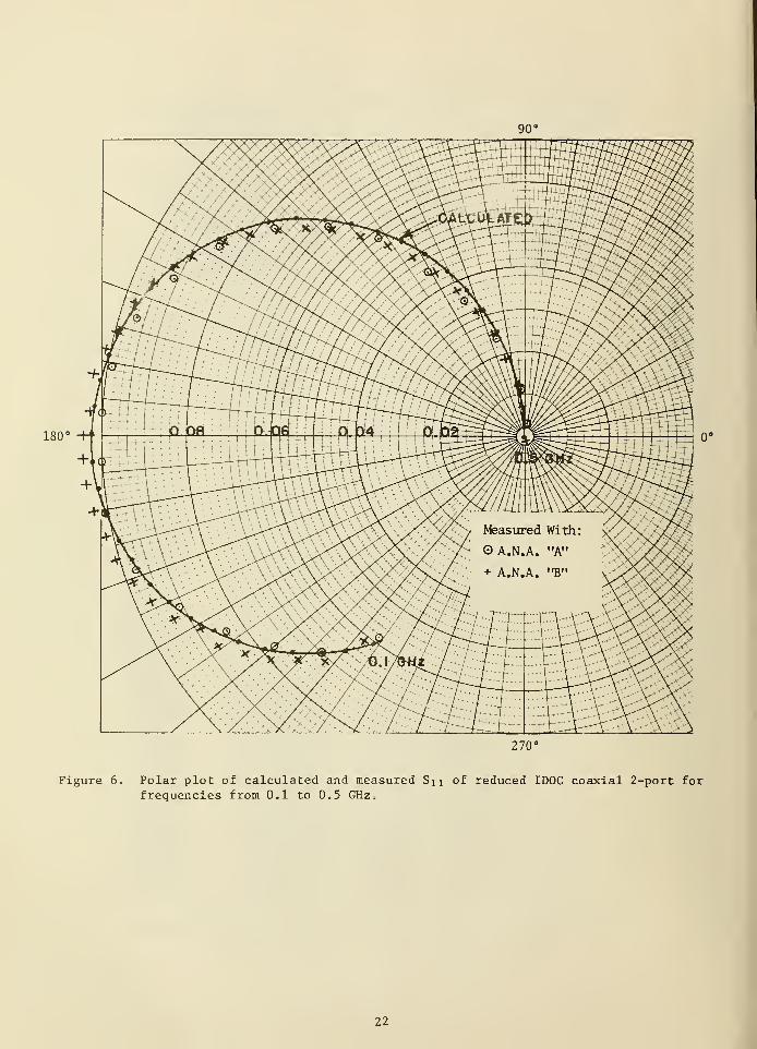
Figure 6. Polar plot of calculated and measured S, , of reduced IDOC
coaxial 2-port for frequencies from 0.1 to 0.5 GHz 22
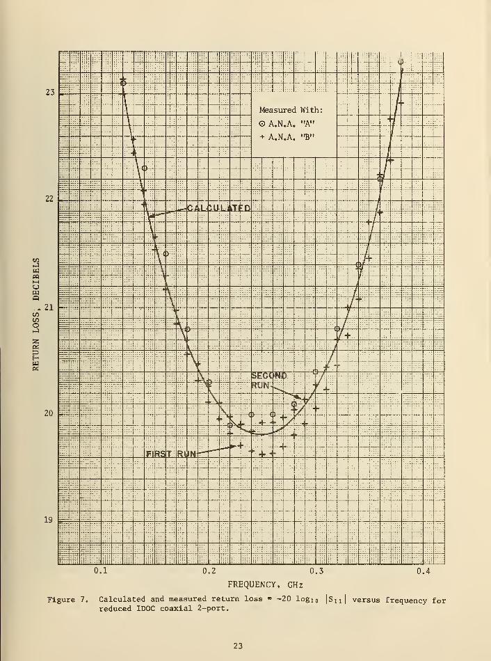
Figure 7. Calculated and measured return loss = -20 log,n
| S,1
|versus
frequency for reduced IDOC coaxial 2-port 23
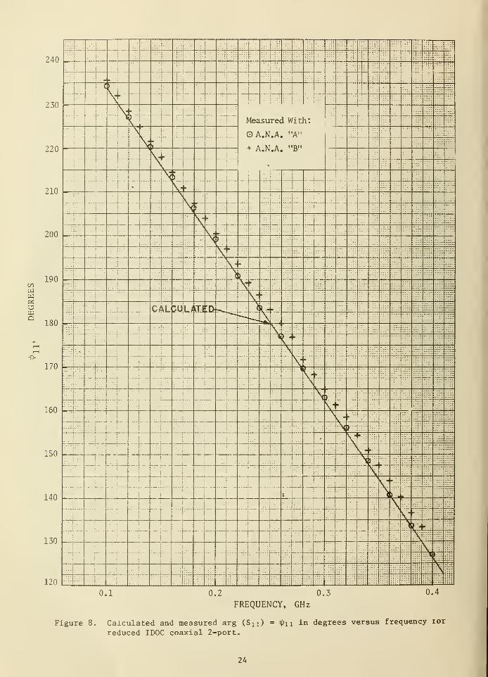
Figure 8. Calculated and measured arg (S, , ) = ij>, - in degrees versus
frequency for reduced IDOC coaxial 2-port 24
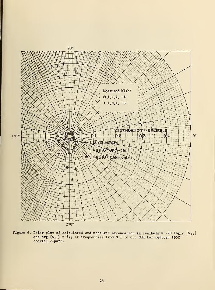
Figure 9. Polar plot of calculated and measured attenuation in decibels
= -20 log, „ |S_,|and arg (S,,,) = if/_, at frequencies from 0.1
to 0.5 GHz for reduced IDOC coaxial 2-port. ;25
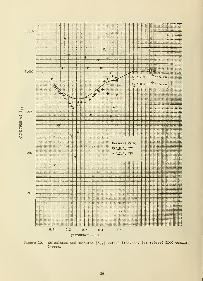
Figure 10. Calculated and measured |S-,| versus frequency for reduced
IDOC coaxial 2-port 26
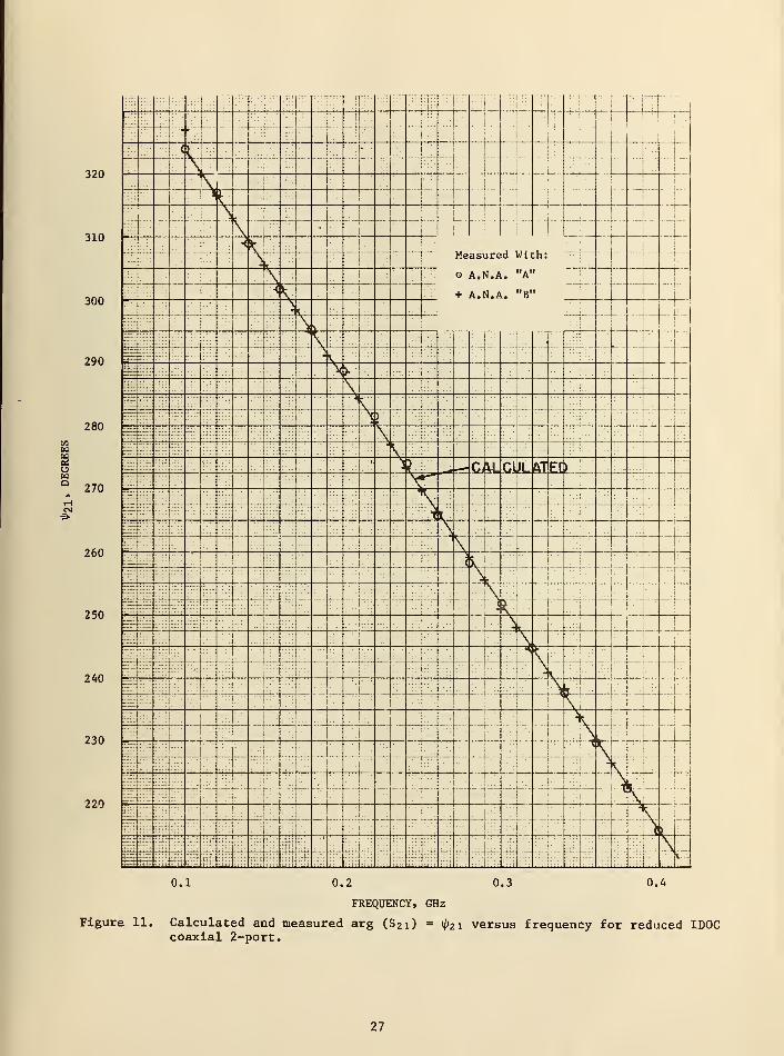
Figure 11. Calculated and measured arg (So-i) = iK, versus frequency for
reduced IDOC coaxial '2 -port 27
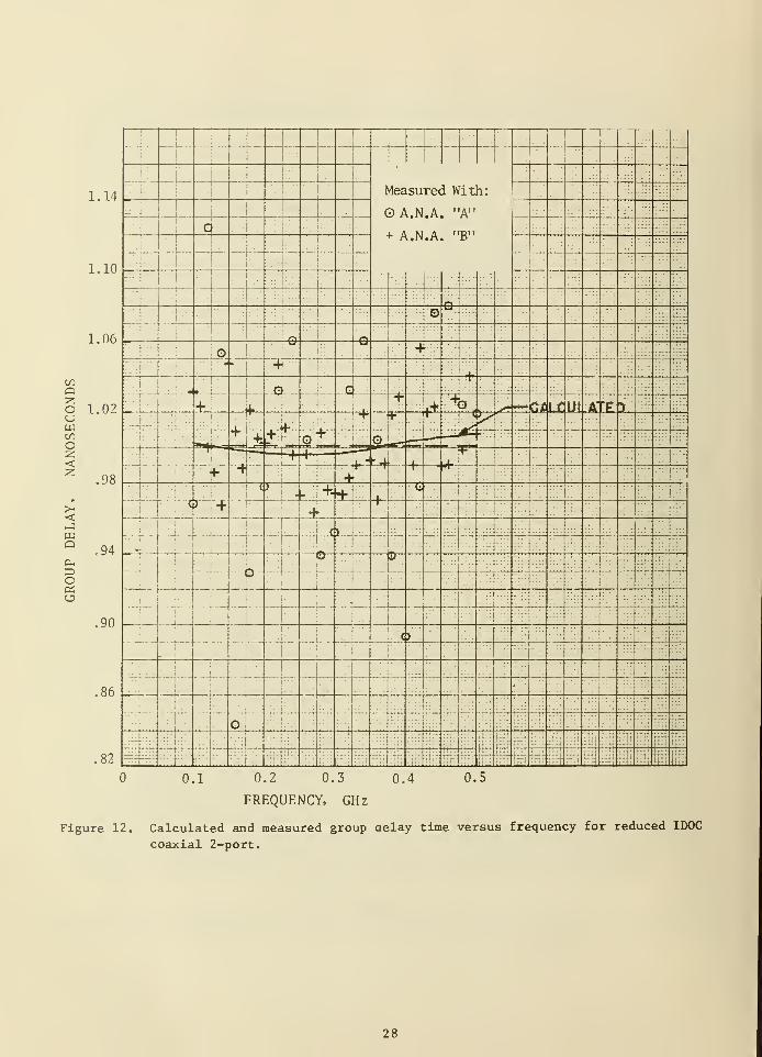
Figure 12. Calculated and measured group delay versus frequency forreduced IDOC coaxial 2-port 28
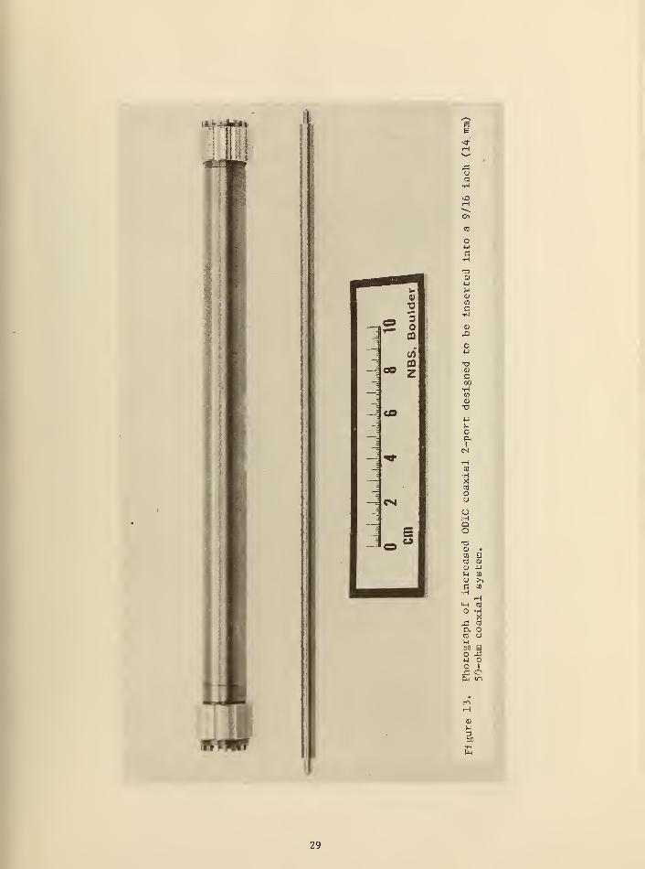
Figure 13. Photograph of increased ODIC coaxial 2-port designed to beinserted into a 9/16 inch (14 mm) 50-ohm coaxial system 29
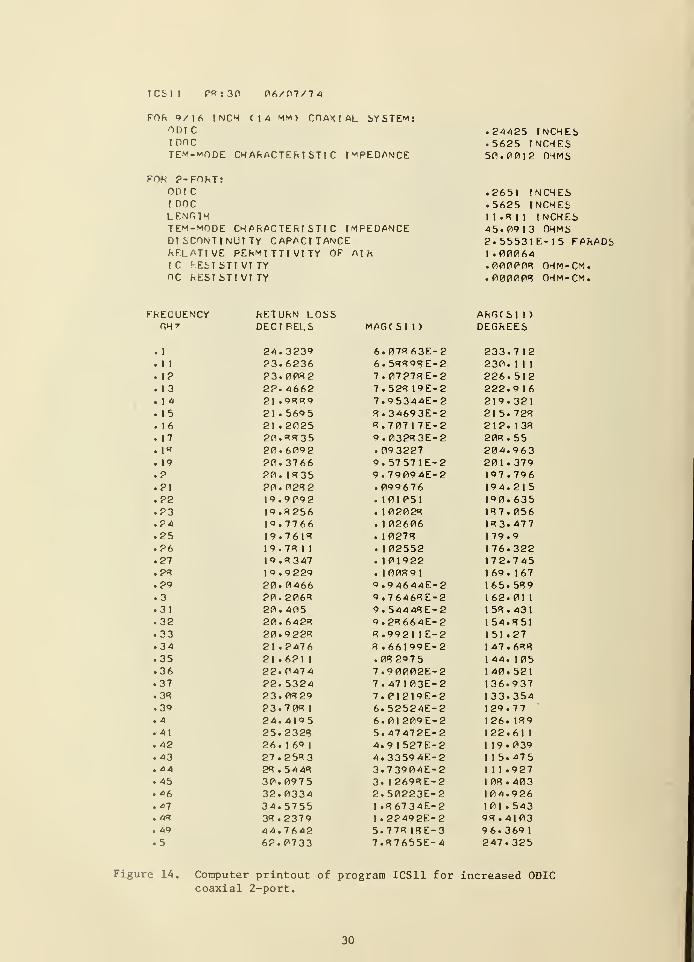
Figure 14. Computer printout of program ICS11 for increased ODICcoaxial 2-port 30
Figure 15. Computer printout of program ICS21 for increased ODICcoaxial 2-port 31
iv
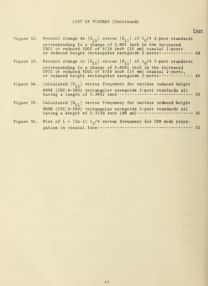
LIST OF FIGURES (Continued)
Page
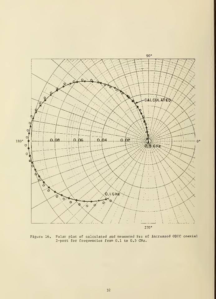
Figure 16. Polar plot of calculated and measured S, , of increased ODIC
coaxial 2-port for frequencies from 0.1 to 0.5 GHz 32
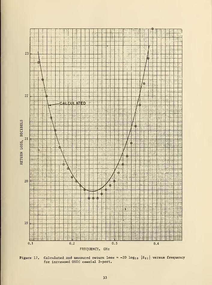
Figure 17. Calculated and measured return loss = -20 log,n|S,,| versus
frequency for increased ODIC coaxial 2-port 33
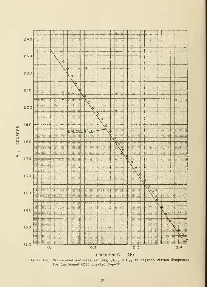
Figure 18. Calculated and measured arg (S,,) = iK , in degrees versus
frequency for increased ODIC coaxial 2-port 34
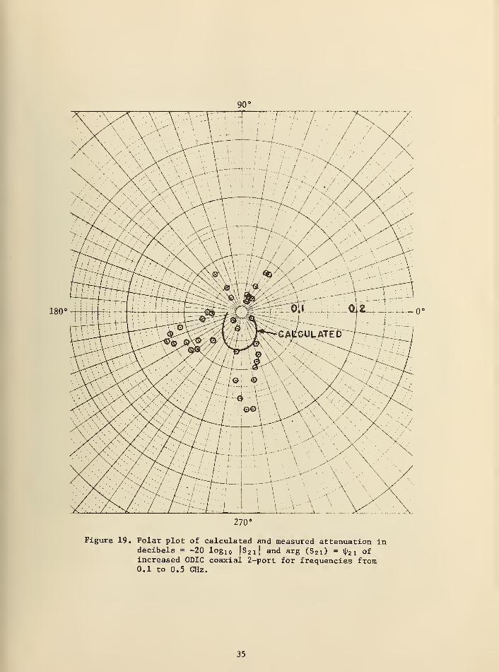
Figure 19 . Polar plot of calculated and measured attenuation in
decibels = -20 log1Q l
s21 l
and ar9 (S21
)=
^21 ° f increased
ODIC coaxial 2-port for frequencies from 0.1 to 0.5 GHz. 35
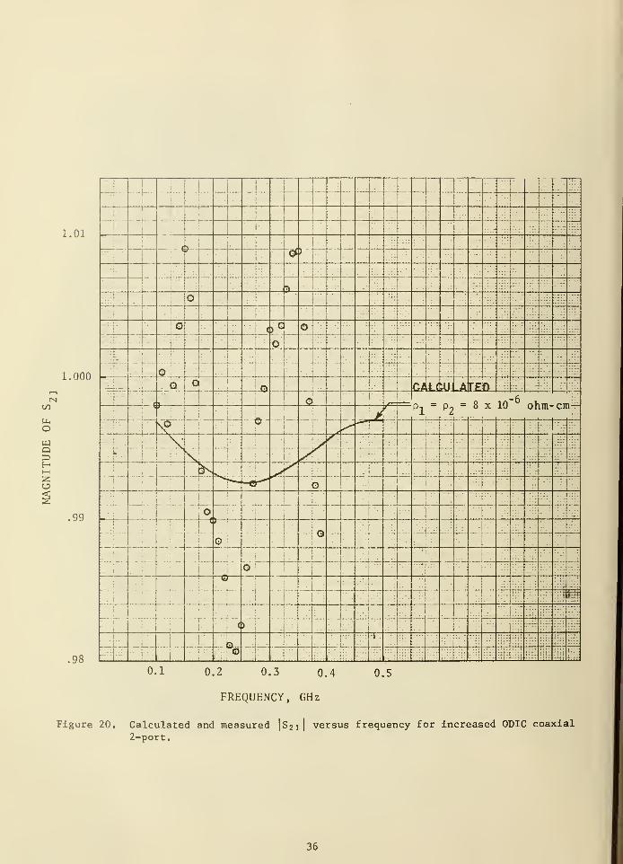
Figure 20. Calculated and measured |S~,| versus frequency for increased
„ ODIC coaxial 2-port 36
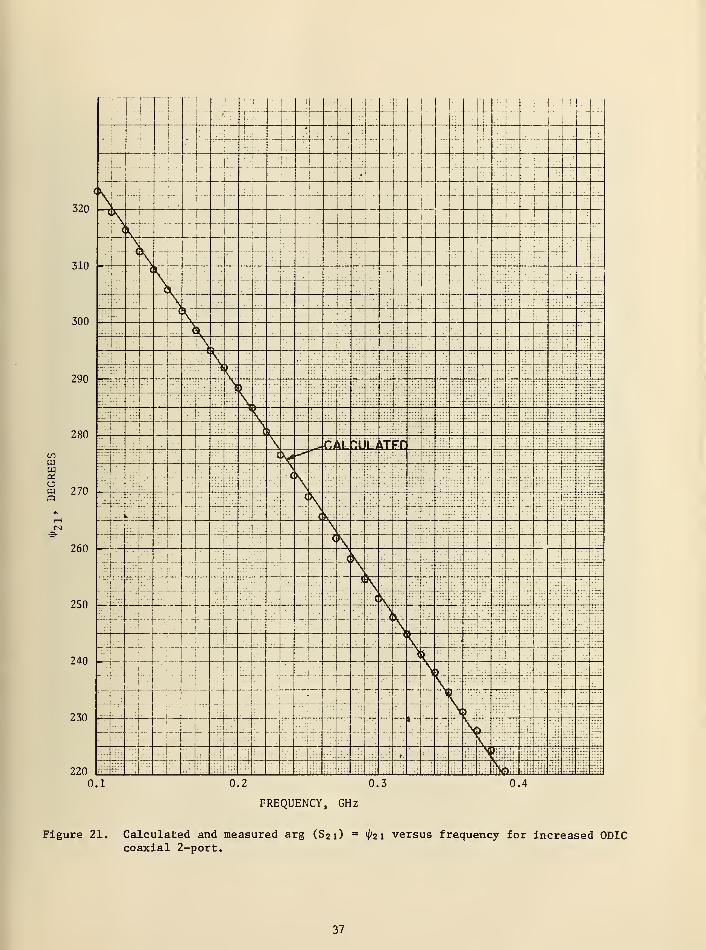
Figure 21. Calculated and measured arg (S?-,) =
i> 7-, versus frequency for
increased ODIC coaxial 2-port 37
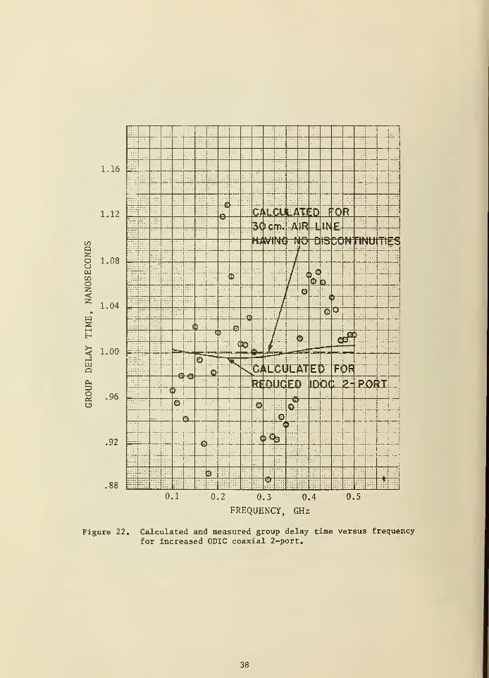
Figure 22. Calculated and measured group delay versus frequency forincreased ODIC coaxial 2-port 38
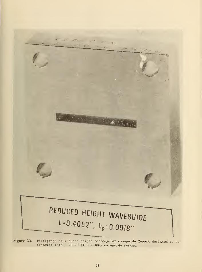
Figure 23. Photograph of reduced height rectangular waveguide 2-portdesigned to be inserted into a WR90 (IEC-R-100) waveguidesystem 39
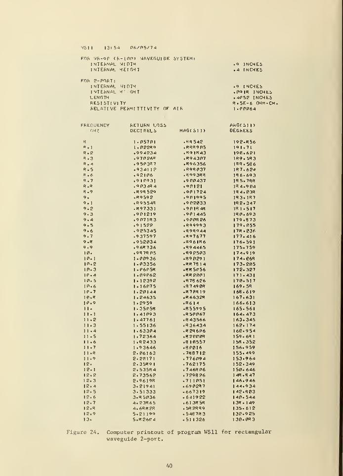
Figure 24. Computer printout of program WS11 for rectangular waveguide2-port 40
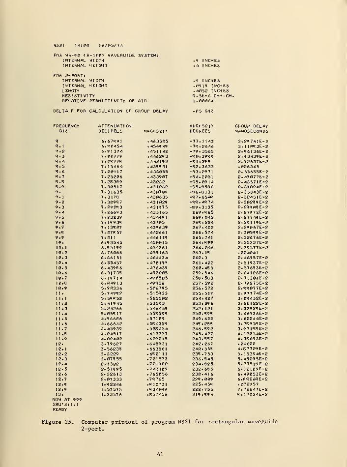
Figure 25. Computer printout of program WS21 for rectangular waveguide2-port 41
Figure 26. Polar plot of calculated and measured S.. , and S~, of rec-
tangular waveguide 2-port for frequencies from 8 to 13 GHz 42
Figure 27. Calculated and measured return loss = -20 log,n|S,,| versus
frequency for rectangular waveguide 2-port 43
Figure 28. Calculated and measured arg (S,,) = iK , in degrees versus
frequency for rectangular waveguide 2-port 44
Figure 29. Calculated and measured attenuation = -20 log,n|S
?, | versus
frequency for rectangular waveguide 2-port 45
Figure 30. Calculated and measured arg (S?
-,) = ip~, in degrees versus
frequency for rectangular waveguide 2-port 46
Figure 31. Calculated and measured group delay time versus frequencyfor rectangular waveguide 2-port 47
LIST OF FIGURES (Continued)
Page
Figure 32. Percent change in |S , | versus |S,,| of ^G/4 2-port standards
corresponding to a change of 0.001 inch in the increasedODIC or reduced IDOC of 9/16 inch (14 mm) coaxial 2-portsor reduced height rectangular waveguide 2-ports 48
Figure 33. Percent change in | S,,
| versus |S,,| of X„/4 2-port standards
corresponding to a change of 0.0001 inch in the increasedODIC or reduced IDOC of 9/16 inch (14 mm) coaxial 2-ports,or reduced height rectangular waveguide 2-ports 49
Figure 34. Calculated |S,,| versus frequency for various reduced height
WR90 (IEC-R-100) rectangular waveguide 2-port standards allhaving a length of 0.4052 inch 50
Figure 35. Calculated | S, , | versus frequency for various reduced height
WR90 (IEC-R-100) rectangular waveguide 2-port standards allhaving a length of 0.3150 inch (80 mm) 51
Figure 36. Plot of L = (2n-l) Ar/4 versus frequency for TEM mode propa-
gation in coaxial line 52
VI
CALCULATED AND MEASURED Sn , S21
, AND GROUP DELAY FOR
SIMPLE TYPES OF COAXIAL AND RECTANGULAR WAVEGUIDE 2 -PORT STANDARDS
by
R.W. Beatty
ABSTRACT
Formulas, simple computer programs, graphs and tables aregiven to aid in the design and construction of 2 -port standardsfor rectangular waveguide and coaxial line. Only standards con-sisting of reduced height waveguide, increased ODIC (outsidediameter of inner conductor), or reduced IDOC (inside diameterof outer conductor) coaxial line are considered. Examples ofthe calculation of S
1, , S„, and group delay, and their measure-
ment with automatic network analyzers are given. Some of theimportant sources of error in the standards are discussed anddesign data are presented for specific standards
.
Key words: Automatic network analyzers; coaxial; coaxial linestep discontinuities; group delay; scattering coefficients;standards; 2 -ports; waveguide; waveguide discontinuities.
1. INTRODUCTION
One can calculate the complex scattering coefficients S, .. and S ?? and
the group delay x of 2-port standards having simple geometries. These
standards are useful for monitoring the performance of computer-controlled
automatic network analyzers (A.N. A.) and for evaluating the accuracy of
their measurements over broad frequency ranges. They may have additional
uses in future developments.
There are many possible types of 2-port standards for which the above
parameters may be calculated. Some examples of simple steps in diameters
of inner and outer conductors of coaxial line and in the heights of rec-
tangular waveguide are illustrated in figure l(a-j). However, only three
types are considered here [1] . They are the reduced IDOC (inside diameter
of outer conductor) type of figure 1(b), the increased ODIC (outside
diameter of inner conductor) of figure 1(c), and the reduced height (hR )
type of figure l(j). These three types are chosen for their simplicity,
ease of construction, and accuracy. For a given value of |S,,| in the
range > | S, , | > 0.6, the increased ODIC type of 2-port (used by Whinnery
and Jamieson in 1944 [2]), has a somewhat greater sensitivity to dimensional
error than the reduced IDOC type but is easier to make and more economical.
In use, the 2-port standards are inserted into a standard coaxial line
or rectangular waveguide system at the output of an A.N. A. and their param-
eters measured over broad frequency ranges . One then compares the calcu-
lated and measured values in order to assess the performance and accuracy
of the A.N. A.
In the following, formulas and simple computer programs are given, as
well as some examples of calculated and measured results.
The accuracy of the calculated results are discussed. Means of esti-
mating uncertainties due to the more important sources of error are de-
scribed. Finally, design data is given for specific standards.
2. FORMULAS FOR CALCULATION
As shown in figure 2, an equivalent circuit for the above types of
2 -port standards includes the normalized equivalent discontinuity susceptance
^— and the attenuation a D of the section of coaxial line or waveguide.OR Using straightforward circuit analysis [3] , one can derive the following
formulas for S, , and S-, .
11
21
(1 + r - jbr)(l - ^ - jb)e" 2yL
+ (1 - r - ibrl (1 + - +(1 - r - jbr)(l jb)
(1 r + jbr)(l - i- - jb)e-2yL
+
4e" YL
(1 + r + jbr)(l + - + jb)
(1 - r + jbr) (1 - jb)e-2yL
+ (1 + r + jbr) CI + | + jb)
(1)
(2)
where
r =OR
YON
b = Y = a.
OR
. 2-n+
J —
.
L = length of 2-port,
r = the ratio of the characteristic admittances of the 2-port 's wave-
guide and of the external waveguide system,
and A„ = waveguide wavelength.
Additional parameters used in calculating S, -, and S?
, for rectangular wave-
guide (TE,n
mode) and for coaxial line (TEM mode) are given in table 1.
The group delay parameter, xr ,
is defined in terms of \Jj--i ithe argument
of S?
, , as follows
.
-d ij>
21
dco
-1
2-n
d i> 21(3)
df
Alternately, we can write
-1 .. .JA *21
x r= — limit
b2t\ Af->0^ Af
(4)
where A i|>
21is the increment in 4>
21 ±n degrees corresponding to a given
increment Af. For finite Af,
G ' l5J
where
360 (fH
- fL )
f„ = f + 1/2 (Af), fT
= f - 1/2 (Af) , and Af << f,
We use eq (5) in calculating t„ for 2 -port standards, choosing Af < 0.1 f.
(One can test whether or not Af has been chosen to be sufficiently small by
recalculating with a still smaller Af and comparing the differences in the
t 's obtained in the two calculations. Of course, if Af is made too small,
errors in calculation will result as one reaches the limits of computer
capability. It is not usually difficult to tell when this happens.)
3. COMPUTER PROGRAMS
In order to make the results widely useful, simple computer programs
have been developed in BASIC language. These have been designated as CS11,
CS21, ICS11, and ICS21 for coaxial 2 -ports, and WS11 and WS21 for rectangular
waveguide. They are reproduced in the appendix to this note and are based
on eqs (1) , (2) , and (5)
.
At the beginning of the programs the required input data and the cal-
culated parameters are listed. Note that the computer programs WS11 and WS21
calculate the discontinuity susceptance from published formulas [7], but
one must presently determine this separately in the case of coaxial lines 1
and insert the correct value into the program. Programs CS21 and WS21 cal-
culate group delay xr
as well as both magnitudes and arguments of S~,
.
Calculation of coaxial line step capacitances is based upon the analysis ofWhinnery, Jamieson, and Robbins, 1944 [8] and is aided by the work of Somlo,1967 [9] and Jurkus , 1972 [10]. The step capacitances vary slowly with fre-quency up to the highest recommended frequencies for coaxial line and thisfrequency variation is presently neglected in computer programs CS11, CS21,ICS11, and ICS21. The step capacitances can also be determined by measuring;tep c
'illithe frequencies where | S,
,| is going through deep minima,
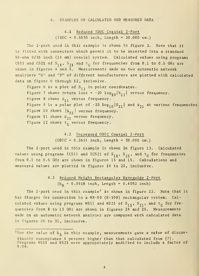
4. EXAMPLES OF CALCULATED AND MEASURED DATA
4 .
1
Reduced IDOC Coaxial 2-Port
(IDOC = 0.5135 inch, Length = 30.000 cm.)
The 2-port used in this example is shown in figure 3. Note that it
is fitted with connectors which permit it to be inserted into a standard
50 -ohm 9/16 inch (14 mm) coaxial system. Calculated values using programs
CS11 and CS21 of S, , , S?
, and T-, for frequencies from 0.1 to 0.5 GHz are
shown in figures 4 and 5. Measurements made on two automatic network
analyzers "A" and "B" of different manufacturers are plotted with calculated
data on figure 6 through 12, inclusive.
Figure 6 is a plot of S, , in polar coordinates.
Figure 7 shows return loss = -20 log,n|S, ,| versus frequency.
Figure 8 shows ij>, , versus frequency.
Figure 9 is a polar plot of -20 l°gi(J S 21 1an<* ^?1 at var i° us frequencies
Figure 10 shows |s„, | versus frequency.
Figure 11 shows i|j
?, versus frequency.
Figure 12 shows t„ versus frequency.
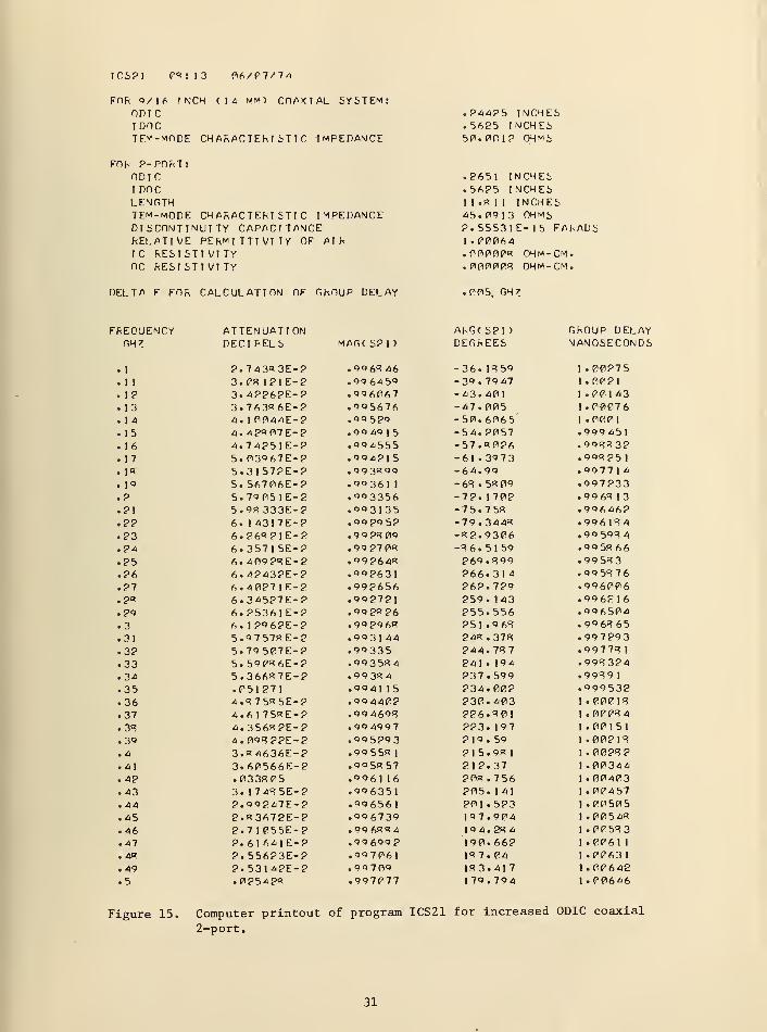
4.2 Increased ODIC Coaxial 2-Port
(ODIC = 0.2651 inch, Length = 30.000 cm.)
The 2-port used in this example is shown in figure 13. Calculated
values using programs ICS11 and ICS21 of S, , , S_, , and t„ for frequencies
from 0.1 to 0.5 GHz are shown in figures 15 and 15. Calculations and
measured values are plotted in figures 16 to 22, inclusive.
4 . 3 Reduced Height Rectangular Waveguide 2 -Port
(hR
= 0.0918 inch, Length = 0.4057 inch)
The 2-port used in this example 2 is shown in figure 23. Note that it
has flanges for connection to a WR-90 (R-100) rectangular system. Cal-
culated values using programs WS11 and WS21 of S, , , S~, , and x„ for fre-
quencies from 8 to 13 GHz are shown in figures 24 and 25. Measurements
made on an automatic network analyzer are compared with calculated data
in figures 26 to 31, inclusive.
2 For the value of hR
in this example, measurements gave a value of discon-
tinuity susceptance 4 percent higher than that calculated from [7]
.
Programs WS11 and WS21 were appropriately modified to include a factor of1.04.
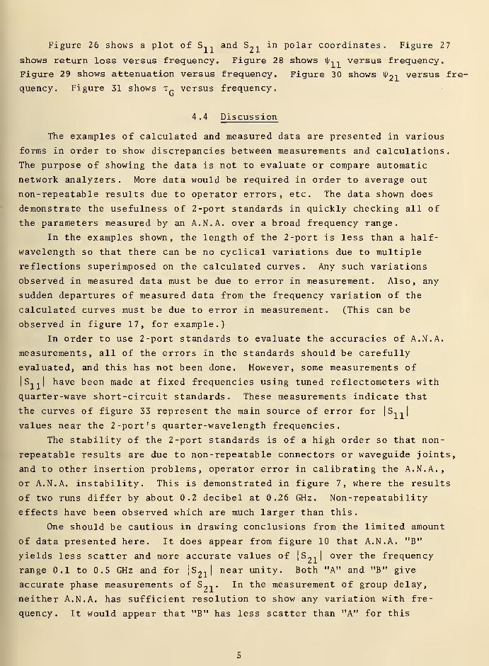
Figure 26 shows a plot of S, , and S--. in polar coordinates. Figure 27
shows return loss versus frequency. Figure 28 shows ijj,, versus frequency.
Figure 29 shows attenuation versus frequency. Figure 30 shows 4>2 i
versus fre-
quency. Figure 31 shows ir versus frequency.
4 .4 Discussion
The examples of calculated and measured data are presented in various
forms in order to show discrepancies between measurements and calculations.
The purpose of showing the data is not to evaluate or compare automatic
network analyzers . More data would be required in order to average out
non-repeatable results due to operator errors, etc. The data shown does
demonstrate the usefulness of 2 -port standards in quickly checking all of
the parameters measured by an A.N. A. over a broad frequency range.
In the examples shown, the length of the 2-port is less than a half-
wavelength so that there can be no cyclical variations due to multiple
reflections superimposed on the calculated curves. Any such variations
observed in measured data must be due to error in measurement. Also, any
sudden departures of measured data from the frequency variation of the
calculated curves must be due to error in measurement. (This can be
observed in figure 17, for example.)
In order to use 2-port standards to evaluate the accuracies of A.N. A.
measurements, all of the errors in the standards should be carefully
evaluated, and this has not been done. However, some measurements of
|S,,| have been made at fixed frequencies using tuned reflectometers with
quarter-wave short-circuit standards. These measurements indicate that
the curves of figure 33 represent the main source of error for |.S, ,|
values near the 2 -port's quarter-wavelength frequencies.
The stability of the 2-port standards is of a high order so that non-
repeatable results are due to non-repeatable connectors or waveguide joints,
and to other insertion problems, operator error in calibrating the A.N. A.,
or A.N. A. instability. This is demonstrated in figure 7, where the results
of two runs differ by about 0.2 decibel at 0.26 GHz. Non-repeatability
effects have been observed which are much larger than this.
One should be cautious in drawing conclusions from the limited amount
of data presented here. It does appear from figure 10 that A.N. A. "B"
yields less scatter and more accurate values of|S _ -,
]over the frequency
range 0.1 to 0.5 GHz and for |S21 |
near unity. Both "A" and "B" give
accurate phase measurements of S--.. In the measurement of group delay,
neither A.N. A. has sufficient resolution to show any variation with fre-
quency. It would appear that "B" has less scatter than "A" for this
particular 2-port over the frequency range 0.1 to 0.5 GHz. The results of
figure 31 show that for a different 2-port, measurements of group delay with
A.N. A. "A" stil] exhibit considerable scatter, but show the correct fre-
quency dependence of group delay.
5. DISCUSSION OF ERRORS
Although a complete investigation of all sources of error in S1 1
, S_,,
and t„ of the standards is desirable, it is not included in this report in
order not to delay publication of useful information. The error in S, , due
to uncertainty in the discontinuity capacitance is very small at frequencies
for which the length of the 2-port is A„/4, but becomes large at Xr/2
frequencies. Similarly, the value of S, . is insensitive to variations in
the resistivity of the metal, except at and near X^/2 frequencies. The
actual surface resistivity will vary with the fabrication process used. One
can by trial and error make the calculated data fit the measured data at
and near the A„/2 frequencies by choosing suitable values of resistivity and
step capacitance and inserting these values in the appropriate computer
programs CS11, ICS11, or WS11. The error in S?
, due to uncertainty in the
resistivity of the metal is also greatest at X_/2 frequencies. Thus, the
best accuracy is expected to occur at and near X„/4 frequencies. It is
felt that at present, the errors in calculated results are likely to be less
than the errors in measured results at most frequencies, except near fre-
quencies at which|S -, -,
|is going through deep minima.
Some of the sources of error are the following:
1. Dimensional tolerances in construction
a. uncertainty in reduced height or reduced IDOC
,
b. uncertainty in width or in ODIC,
c. uncertainty in length.
2. Approximations in calculation of equivalent discontinuity susceptance
a. lack of rigor in theory,
b. errors in formulas,
c. errors in computer programs.
3. Faulty construction of standard
a. poor surface finish,
b . burrs
,
c. lack of surface flatness or circularity.
4. Uncertainty in dissipative loss
a. attenuation,
b. losses at discontinuities,
c. losses at flanges or connectors.
5. Insertion errors
a. misalignment
b. system into which 2-port is inserted has non-standard dimen-
sions and is different on one side of insertion point than
the other.
A few of the major sources of uncertainty will be discussed as follows
A given uncertainty in the reduced height or reduced IDOC produces a cor-
responding uncertainty in the calculated value of | S, ,|
at frequencies for
which the length of the 2-port is an odd number of quarter wavelengths.
For small errors, we may use the following expressions.
For reduced height rectangular waveguide the fractional error in
11is
d|sn s I
2bll!
d hR
(6)
1 11'
'11' R
This is derived by differentiating the relationship
'h,
11 V 2(7)
^R+ 1
from [1] , which holds closely at frequencies where L is an odd number of
Ap/4. For reduced IDOC coaxial line, the corresponding fractional error in
|sn |
IS
d|sn |
1 -I
s lll2 d ( Z 0R>
|sn |
|sn |
>
7^OR
d|sn |
1 -I
s lll2
59.9392
or
d(IDOCR )
11 11 'ORIDOC
(8)
(9)
R
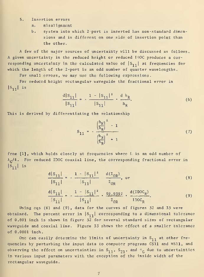
Using eqs (6) and (9) , data for the curves of figures 32 and 33 were
obtained. The percent error in |S,,| corresponding to a dimensional tolerance
of 0.001 inch is shown in figure 32 for several standard sizes of rectangular
waveguide and coaxial line. Figure 33 shows the effect of a smaller tolerance
of .0001 inch.
One can easily determine the limits of uncertainty in S, , at other fre-
quencies by perturbing the input data to computer programs CS11 and WS11, and
observing the effect on uncertainties in S, -, , S?
, , and t„ due to uncertainties
in various input parameters with the exception of the inside width of the
rectangular waveguide.
If the inside width of the rectangular waveguide 2-port is different
than the width of the waveguide system into which the 2-port is inserted,
unwanted reflections will be produced which can cause error. Evaluation
of the uncertainty due to this error source can be accomplished using
published formulas [7], but will not be discussed further in this note.
6. DESIGN INFORMATION
A design technique which has been used is to select values of |S11
that one would like to produce and then calculate the reduced height h D ,
increased ODIC, or reduced IDOC required to obtain these values of |S,,|
at frequencies for which the length L of the 2-port is an odd number of
Ar/4 , neglecting the effects of discontinuity susceptance.
Table II gives values of hR
corresponding to various values of |S,,|
for WR90 (R-100) rectangular waveguide. Table III gives values of increased
ODIC and reduced IDOC for 9/16 inch (14 mm) coaxial 2-ports and table IV
gives values of increased ODIC and reduced IDOC for 7 mm coaxial 2-ports.
Table V gives approximate 3 step capacitances versus | S, , | for quarter
wavelength 7 mm and 9/16 inch (14 mm) coaxial 2-ports using either increased
ODIC or reduced IDOC.
The choice of length of the 2-port is arbitrary and some choices
which have proven convenient are the following: for WR90 (R-100) rec-
tangular waveguide, L = 0.4052 inch, ~*G/4 @ 9.8 GHz, L = 0.8104 inch,
~A„/2 @ 9.8 GHz. Figure 34 shows how |S,,| varies across the frequency
range for 2-ports having a length L = 0.4052 inch. A flatter frequency
response may be obtained as shown in figure 35 by choosing L = 0.3150 inch
(80 mm), ~^G/4 @ 11.43067 GHz.
In order to facilitate design for still other standard sizes of
rectangular waveguide or coaxial line, simple computer programs may be
used. Programs IDOC and ODIC calculate the reduced IDOC and increased ODIC
for quarter wavelength coaxial line 2-ports corresponding to chosen values
of |S,,|. Program HR calculates values of reduced height hR
of quarter
guide-wavelength rectangular waveguide 2-ports for chosen values of |S,,|.
These programs appear in the appendix.
3 The approximate values of step capacitance were obtained by interpolatingin the tables of Somlo, 1967 [9], for t = 2.3025 which corresponds toZ = 50 ohms. More accurate values will be available later both from
measurements and from the computer programs of Somlo [9] and Jurkus [10].
In designing coaxial 2 -ports to have many odd numbers of quarter-wave
resonances, figure 36 is useful. At present, the calculated values of S,
,
are most accurate near these resonances and least accurate at frequencies
where | S, , | is minimum. Therefore, it might be advantageous to have a
second 2-port standard for which | S, , | is nearly maximum at frequencies
where | S, , | is minimum for the first 2-port standard.
7. CONCLUSION
Two-port standards in rectangular waveguide or coaxial line may be pro-
duced by reducing the height of a waveguide section, increasing the ODIC or
reducing the IDOC of a coaxial line section. They may be designed to produce
desired |S,,| values at chosen frequencies. After design, the complex S,1
and S«, and the group delay may readily be calculated over any desired fre-
quency range. The accuracy of the calculated data at and near A„/4 fre-
quencies is better than present measurement accuracy with many automatic
network analyzers. At and near the Xr /2 frequencies, the measured data
may be assumed to be more accurate, and used to adjust the values of surface
resistivity and shunt susceptance in the calculations. The 2-port standards
are very stable and can be used for quickly checking performance and accuracy
of automatic network analyzers over broad frequency ranges.
8. ACKNOWLEDGMENTS
The assistance of a number of people made this work possible. At NBS,
George H. Fentress was the principal assistant in design, measurement, and
presentation of results; Philip F. Biddle helped with mechanical design;
William E. McNaney made accurate dimensional measurements and Fred F. Jeffers
helped make measurements using an automatic network analyzer. Measurements
using a different automatic network analyzer were kindly made by
T.E. McKenzie, C.C. Gorss, and R.L. Moynihan of the General Radio Company,
Bolton, Mass. Comments and suggestions were received from William E. Little
and Clarence C. Cook of NBS, and Brent Palmer of the Hewlett-Packard Company.
9. APPENDIX
The following computer programs are given in the appendix; CS11, CS21,
ICS11, ICS21, WS11, WS21, ODIC, IDOC, and HR. The purpose of each program
is described in the REM statements, and use of the programs is intended to
be evident to those having an elementary knowledge of computer BASIC
language.
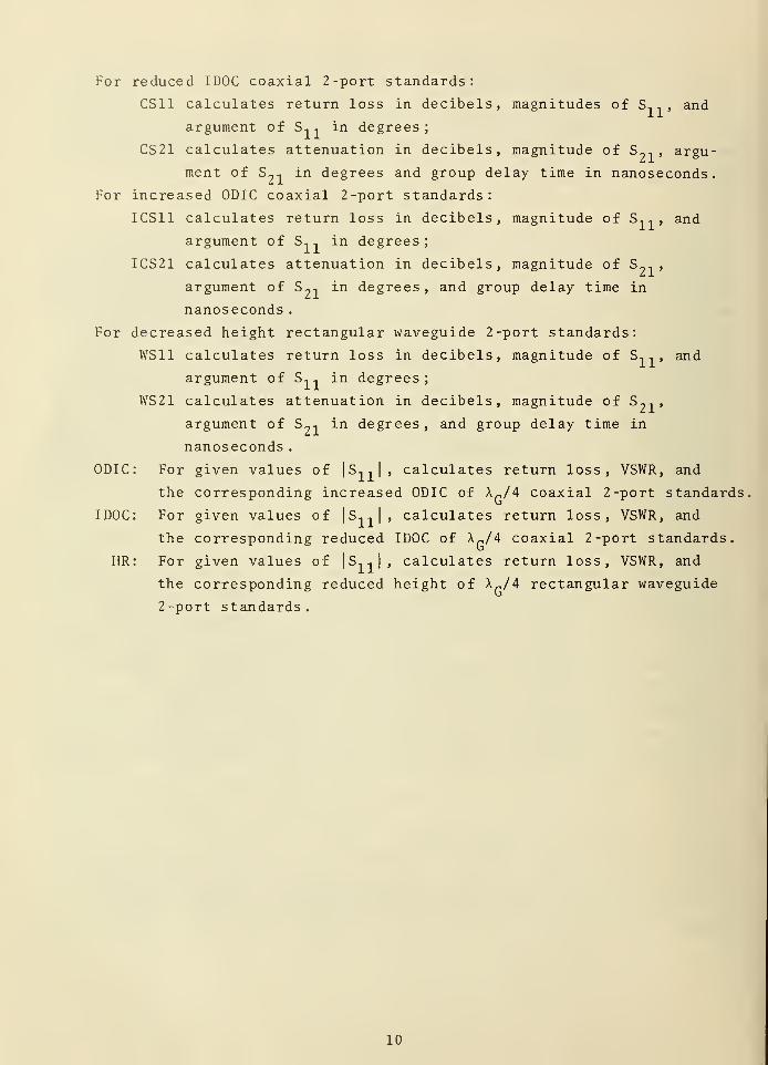
For reduced IDOC coaxial 2-port standards:
CS11 calculates return loss in decibels, magnitudes of S, , and
argument of S, -, in degrees;
CS21 calculates attenuation in decibels, magnitude of S?1 , argu-
ment of S^-, in degrees and group delay time in nanoseconds.
For increased ODIC coaxial 2-port standards:
ICS11 calculates return loss in decibels, magnitude of S, .. , and
argument of S, , in degrees;
ICS21 calculates attenuation in decibels, magnitude of S~,
,
argument of S?1
in degrees , and group delay time in
nanoseconds .
For decreased height rectangular waveguide 2-port standards:
WS11 calculates return loss in decibels, magnitude of S,, , and
argument of S, , in degrees;
WS21 calculates attenuation in decibels, magnitude of S-,
,
argument of S~, in degrees, and group delay time in
nanoseconds
.
ODIC: For given values of|S _. ->
|, calculates return loss, VSWR, and
the corresponding increased ODIC of A„/4 coaxial 2-port standards
For given values of |S,,|, calculates return loss, VSWR, and
the corresponding reduced IDOC of X„/4 coaxial 2-port standards.
For given values of | S,, |
, calculates return loss, VSWR, and
the corresponding reduced height of A-/4 rectangular waveguide
2-port standards.
IDOC
HR
10

10. REFERENCES
[1] Beatty, R.W., "2-Port A /4 Waveguide Standard of Voltage Standing-Wave
Ratio," Electronics Letters, 9_, no. 2, 25 January 1973, 24-26.
[2] Whinnery, J.R. and H.W. Jamieson, "Equivalent Circuits for Discontinuities
in Transmission Lines," Proc. I.R.E., 32_, no. 2, Feb. 1944, 98-114.
[3] See for example: Kerns, D.M. and R.W. Beatty, "Basic Theory of Waveguide
Junctions and Introductory Microwave Network Analysis" (Pergamon Press,
New York, New York, 1967).
[4] Pomeroy, A.F., "Waveguide Loss Charts," Electronics, Oct. 1, 1957.
[5] Moreno, T., "Microwave Transmission Design Data" (Dover Publications,
Inc., New York, New York, 1958), 63.
[6] See for example: Brady, M. Michael, "Standard Rectangular Waveguide
Constants" (Transcripta Books, London, 1972).
[7] Marcuvitz, N. (Editor), "Waveguide Handbook" (McGraw Hill Book Company,
Inc., New York, New York, 1951), 296, 307.
[8] Whinnery, J.R., H.W. Jamieson, and T.E. Robbins, "Coaxial -Line Dis-
continuities," Proc. I.R.E., 32., no. 11, Nov. 1944, 695-709.
[9] Somlo, P.I., "The Calculation of Coaxial Line Step Capacitances," IEEE
Trans, on MTT, 1_5, no. 1, Jan. 1967, 48-53.
[10] Jurkus , A., "Computation of Step Discontinuities in Coaxial Line,"
IEEE Trans, on MTT, 20, no. 10, Oct. 1972, 708-709.
11
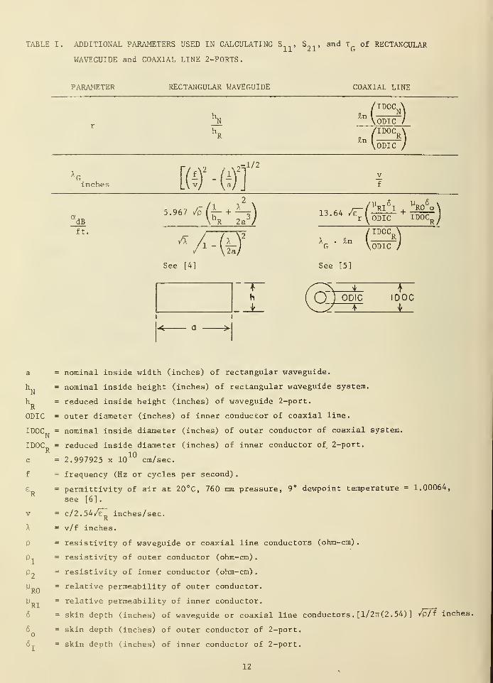
TABLE I. ADDITIONAL PARAMETERS USED IN CALCULATING Sn> S^, and TQ
of RECTANGULAR
WAVEGUIDE and COAXIAL LINE 2-PORTS
.
PARAMETER RECTANGULAR WAVEGUIDE COAXIAL LINE
hN
, /IDCV)
\ODIC /
inches m-offMbft.
5.967 ,£fi- + A_hR 2a
3/
A
See [4]
-(i);
13.64 /iT~
XG
. £n
See [5]
r^ODIC ID0CR /
TIdoO\ODIC /
h
< a >•
* 1
( )
)
ODIC IDOCt 1
nominal inside width (inches) of rectangular waveguide,
nominal inside height (inches) of rectangular waveguide system,
reduced inside height (inches) of waveguide 2-port.
outer diameter (inches) of inner conductor of coaxial line.
IDOC„ = nominal inside diameter (inches) of outer conductor of coaxial system.
a
hN
hR
ODIC
NIDOC
c
f
V
A
P
Pi
RO
B
'RI
reduced inside diameter (inches) of inner conductor of 2-port.
2.997925 x 10¹⁰
cm/sec.
frequency (Hz or cycles per second)
.
permittivity of air at 20°C, 760 ram pressure, 9° dewpoint temperature = 1.00064,
see [6]
.
c/2.54/e inches/sec.K
v/f inches.
resistivity of waveguide or coaxial line conductors (ohm-cm)
.
resistivity of outer conductor (ohm-cm)
.
resistivity of inner conductor (ohm-cm)
.
relative permeability of outer conductor.
relative permeability of inner conductor.
skin depth (inches) of waveguide or coaxial line conductors
.
[1/2tt(2 .54) ] /p/f inches.
skin depth (inches) of outer conductor of 2-port.
skin depth (inches) of inner conductor of 2-port.
12
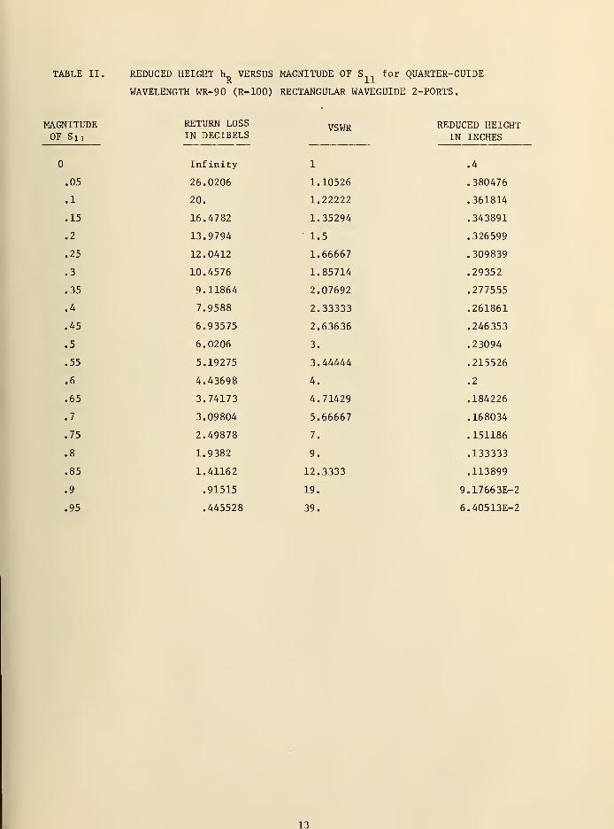
TABLE II. REDUCED HEIGHT h_, VERSUS MAGNITUDE OF S.. for QUARTER-GUIDER XX
WAVELENGTH WR-90 (R-100) RECTANGULAR WAVEGUIDE 2-PORTS
.
MAGNITUDEOF SU
.05
.1
.15
.2
.25
.3
.35
.4
.45
.5
.55
.6
.65
.7
.75
.8
.85
.9
.95
RETURN LOSSIN DECIBELS
VSWR REDUCED HEIGHTIN INCHES
Infinity 1 .4
26.0206 1.10526 .380476
20. 1.22222 .361814
16.4782 1.35294 .343891
13.9794 1.5 .326599
12.0412 1.66667 .309839
10.4576 1.85714 .29352
9.11864 2.07692 .277555
7.9588 2.33333 .261861
6.93575 2.63636 .246353
6.0206 3. .23094
5.19275 3.44444 .215526
4.43698 4. .2
3.74173 4.71429 .184226
3.09804 5.66667 .168034
2.49878 7. .151186
1.9382 9. .133333
1.41162 12.3333 .113899
.91515 19. 9.17663E-2
.445528 39. 6.40513E-2
13
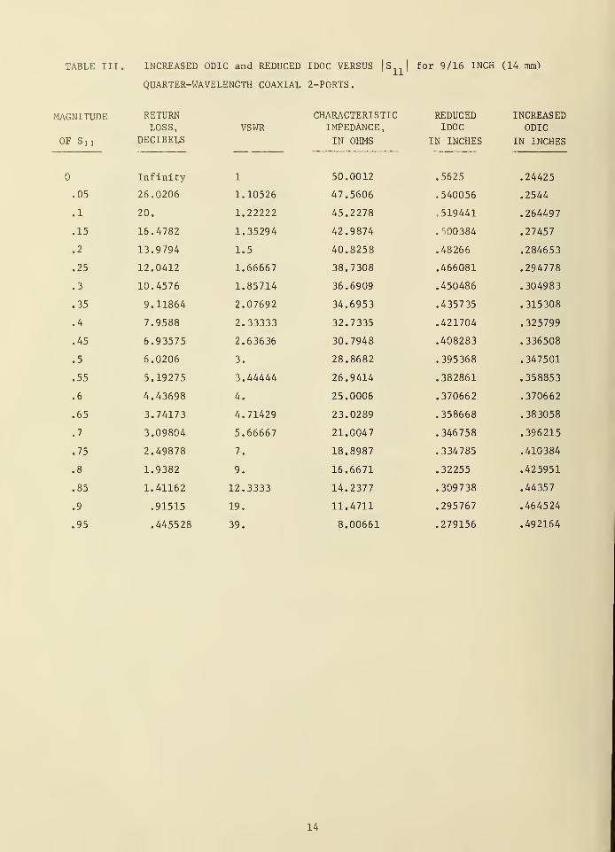
TABLE III. INCREASED ODIC and REDUCED IDOC VERSUS |S|for 9/16 INCH (14 mm)
QUARTER-WAVELENGTH COAXIAL 2-PORTS.
MAGNITUDE RETURN CHARACTERISTIC REDUCED INCREASEDLOSS, VSWR IMPEDANCE, IDOC ODIC
OF Sn DECIBELS
1
IN OHMS IN INCHES IN INCHES
Infinity 50.0012 .5625 .24425
.05 26.0206 1.10526 47.5606 .540056 .2544
.1 20. 1.22222 45.2278 519441 .264497
.15 16.4782 1.35294 42.9874 . 500384 .27457
.2 13.9794 1.5 40.8258 .48266 .284653
.25 12.0412 1.66667 38.7308 .466081 .294778
.3 10.4576 1.85714 36.6909 .450486 .304983
.35 9.11864 2.07692 34.6953 .435735 .315308
.4 7.9588 2.33333 32.7335 .421704 .325799
.45 6.93575 2.63636 30.7948 .408283 .336508
.5 6.0206 3. 28.8682 .395368 .347501
.55 5.19275 3.44444 26.9414 .382861 .358853
.6 4.43698 4. 25.0006 .370662 .370662
.65 3.74173 4.71429 23.0289 .358668 .383058
.7 3.09804 5.66667 21.0047 .346758 .396215
.75 2.49878 7. 18.8987 .334785 .410384
.8 1.9382 9. 16.6671 .32255 .425951
.85 1.41162 12.3333 14.2377 .309738 .44357
.9 .91515 19. 11.4711 .295767 .464524
.95 .445528 39. 8.00661 .279156 .492164
14
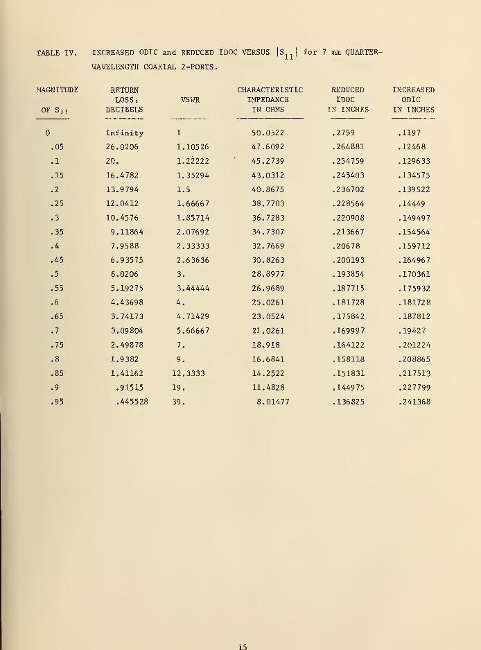
TABLE IV. INCREASED ODIC and REDUCED IDOC VERSUS |S|for 7 mm QUARTER-
WAVELENGTH COAXIAL 2-PORTS.
MAGNITUDE RETURN CHARACTERISTIC REDUCED INCREASEDLOSS, VSWR IMPEDANCE IDOC ODIC
OF Sn DECIBELS IN OHMS IN INCHES IN INCHES
Infinity 1 50.0522 .2759 .1197
.05 26.0206 1.10526 47.6092 .264881 .12468
.1 20. 1.22222 45.2739 .254759 .129633
.15 16.4782 1.35294 43.0312 .245403 .134575
.2 13.9794 1.5 40.8675 .236702 .139522
.25 12.0412 1.66667 38.7703 .228564 .14449
.3 10.4576 1.85714 36.7283 .220908 .149497
.35 9.11864 2.07692 34.7307 .213667 .154564
.4 7.9588 2.33333 32.7669 .20678 .159712
.45 6.93575 2.63636 30.8263 .200193 .164967
.5 6.0206 3. 28.8977 .193854 .170361
.55 5.19275 3.44444 26.9689 .187715 .175932
.6 4.43698 4. 25.0261 .181728 .181728
.65 3.74173 4.71429 23.0524 .175842 .187812
.7 3.09804 5.66667 21.0261 .169997 .19427
.75 2.49878 7. 18.918 .164122 .201224
.8 1.9382 9. 16.6841 .158118 .208865
.85 1.41162 12.3333 14.2522 .151831 .217513
.9 .91515 19. 11.4828 .144975 .227799
.95 .445528 39. 8.01477 .136825 .241368
15
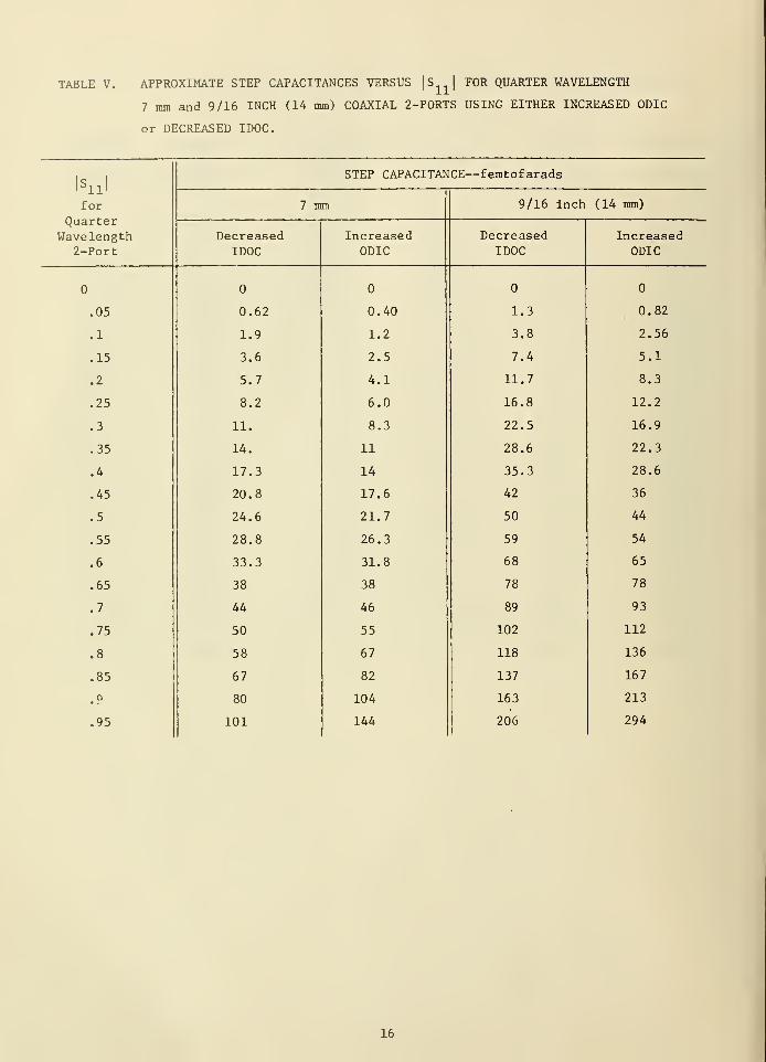
TABLE V. APPROXIMATE STEP CAPACITANCES VERSUS |S|FOR QUARTER WAVELENGTH
7 ram and 9/16 INCH (14 mm) COAXIAL 2-PORTS USING EITHER INCREASED ODIC
or DECREASED IDOC.
|sn l
STEP CAPACITANCE—femtofarads
for
Quarter7 mm 9/16 inch (14 ram)
Wavelength Decreased Increased Decreased Increased2-Port IDOC ODIC IDOC ODIC
.05 0.62 0.40 1.3 0.82
.1 1.9 1.2 3.8 2.56
.15 3.6 2.5 7.4 5.1
.2 5.7 4.1 11.7 8.3
.25 8.2 6.0 16.8 12.2
.3 11. 8.3 22.5 16.9
.35 14. 11 28.6 22.3
.4 17.3 14 35.3 28.6
.45 20.8 17.6 42 36
.5 24.6 21.7 50 44
.55 28.8 26.3 59 54
.6 33.3 31.8 68 65
.65 38 38 78 78
.7 44 46 89 93
.75 50 55 102 112
.8 58 67 118 136
.85 67 82 137 167
.9 80 104 163 213
.95 101 144 206 294
16
a)
b)
c)
d)
COAXIAL LINE2-PORT
D_0DI_c i
-, T
QlDOCR
I DOC
l
i
- t
D IDOCN
i)
" 1
D° DJ-C N
- t
JL
T
COAXIAL LINE,
2-PORT,
J 1—L_
RECTANGULARWAVEGUIDE
1 2-PORT'
d:.Li D
I
T°_DI_C N
D:°iL
ODIC,
D
t
hN
ABCFigure 1. Examples of 2-port standards incorporating simple 'discontinuities in
coaxial line (a-h) and rectangular waveguide (i-j)o Regions A and C
denote nominal coaxial cross-sectional dimensions specified by well-known standards, and region B denotes the 2-port sections havingmodified dimensions.
17
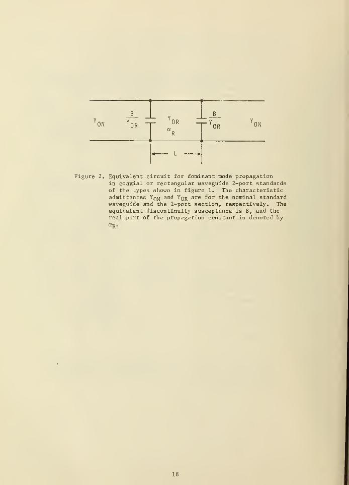
Figure 2. Equivalent circuit for dominant mode propagationin coaxial or rectangular waveguide 2-port standardsof the types shown in figure 1. The characteristicadmittances Yq^ and Yq^ are for the nominal standardwaveguide and the 2-port section, respectively. Theequivalent discontinuity susceptance is B, and thereal part of the propagation constant is denoted byaR .
18
,
.
'.:.. ... ^-v
1 SI; - 1
III' <r
§! !
H
X.ucH\Dr-4
-. cd
l"Oua
i
"''.
•H
X)
4-J
U-
L. 0)
...1JR V c•H
''^bB 1 ,
' o 5 <u
-t--_. _- rQ
".,-|
-4 CO of^S- :::
|;::
|:
!
'§: 4-J
l
|
1
CO T3
cbfl
•H05
0)
1
-= T3
;iBpl H * CO 4-1
'
1 i \ ;. !
"i O
mm -4i
CM
ft* »; :**1 18 *~; ««t H
;. ]£ ', ~J
cd
•H
1 Xta
oo"
:
' •.
-—
~
CM"i
oo; P
j E H; ; ,v|hS£9R I _ u •a e.:.'
—^SBU 4-1
3 to
1 imMm!
'
1 0J to
HI I mWW^ H
I » H4-4 Cd
1
O *H
X! cd
p.,
Icd o
-9 ::
ibo e
IO J34-> OO 1
;;;^|: j;
x oPh in
-9 B .
;' en
V C a)
' n ;
360•H
Li w '<
i
^
19

CS1 ! 08» 56 06/04/74
FOR 9/16 INCH (14 MM) COAXIAL SYSTEM:ODIC .24425 INCHESI DOC .5625 INCHESTEM-MODE CHARACTERISTIC IMPEDANCE 50.0012 OHMS
FOR 2-PORT:ODIC .24425 INCHESI DOC .5185 INCHESLENGTH 11.8 11 INCHESTEM-MODE CHARACTERISTIC IMPEDANCE 45.119 1 OHMSDISCONTINUITY CAPACITANCE 3.8E- 15 FARADSRELATIVE PERMITTIVITY OF AIR 1 .00064IC RESISTIVITY .000002 OHM-CM.OC RESISTIVITY .000008 OHM- CM.
FREQUENCY RETURN LOSS ARG<S1 1)
GHZ DECIBELS MAG(S1 1
)
DEGREES
.1 24.368 6.04782E-2 233.74
.11 23.6677 .065556 230. 137
.12 23.0523 7.03697E-2 226.536
.13 22.5103 7.49005E-2 222.937
.14 22.0331 7.9 131 1E-2 219.34
.15 21 .6137 8.30454E-2 215.746
.16 21 .2468 8.66287E-2 212. 153
.17 20.9279 8.98675E-2 208.563
.18 20.6537 9.27498E-2 204.974
.19 20.4213 .095265 201.387
.2 20.2285 9.74039E-2 197.802
.21 20.0734 9.91587E-2 194.219
.22 19.9547 . 100523 190.637
.23 19.8714 . 101492 187.055
.24 19.8227 . 102062 183.475
.25 19.8083 . 102231 179.894
.26 19.8281 . 101999 176.314
.27 19.8822 . 101366 172.734
.28 19.971 . 100335 1 69 . 1 54
.29 20.0953 9.89088E-2 165.573
.3 20.2562 9.70936E-2 161.991
.31 20.4551 9.48956E-2 1 58 . 409
.32 20.6938 9.23228E-2 154.825
.33 20.9747 8.938 48E-2 151.24
.34 21.3007 8.60924E-2 147.654
.35 21.6753 .082458 144.067
.36 22. 1032 .078 49 5 140.478
.37 22.58 9 7 7.42187E-2 136.889
.38 23.1422 6.96453E-2 133.299
.39 23.7695 6.47923E-2 129.709
.4 24.4836 5.96787E-2 126. 12
.41 25.3001 5.43245E-2 122.533
.42 26.2404 4.87506E-2 1 18.948
.43 27.3348 4.29793E-2 115.37
.44 28.628 1 3.70335E-2 1 1 1.802
.45 30. 1903 3.09373E-2 108.252
.46 32. 1407 2.471 52E-2 104.735
.47 34.7071 1.83926E-2 101.288
.48 38.4197 1. I9954E-2 98.0246
.49 45. 1 127 5.55092E-3 95.5923
.5 60.4747 9.468 13E-4 256.706
Figure 4. Computer printout of program CS11 for reduced IDOC
coaxial 2-port.
20
CS21 09: 18 06/04/74
FOR 9/16 INCH (14 MM) COAXIAL SYSTEM:ODICI DOCTEM-MODE CHARACTERISTIC IMPEDANCE
.24425 INCHES
.5625 INCHES50.0012 OHMS
FOR 2-PORT:ODICI DOCLENGTHTEM-MODE CHARACTERISTIC IMPEDANCEDISCONTINUITY CAPACITANCERELATIVE PERMITTIVITY OF AIRIC RESISTIVITYOC RESISTIVITY
.24425 INCHES
.5185 INCHES1 1 .8 1 1 INCHES45. 1 191 OHMS3.8E-15 FARADS1 .00064.000002 OHM- CM..000008 OHM-CM.
DELTA F FOR CALCULATION OF GROUP DELAY 005 GHZ
FREQUENCY ATTENUATION ARG(S21> GROUP DELAYGHZ DECIBELS MAGCS21) DEGREES NANOSECONDS
.1 2.40454E-2 .997235 -36. 1865 1.00279
.11 2.72331E-2 .99687 -39.79 54 1.00214
.12 3.04672E-2 .99 6498 -43.4019 1.00148
.13 3.37052E-2 .996127 -47.0061 1.00082
.14 .036902 .99576 -50.6078 1.00016
.15 4.00152E-2 .995404 -54.2072 .999523
.16 4.30018E-2 .995061 -57.8044 .99891
.17 4. 58 207 E-
2
.994739 -61.399 4 .998335.18 4.84335E-2 .994439 -64.9925 .997804.19 5.08 046E-2 .994168 -68.5837 .997328.2 .052903 .99 39 28 -72.1733 .996912.21 5.46994E-2 .993722 -75.7615 .996565.22 5.61722E-2 .993554 -79.3486 .996291.23 5.73021E-2 .993425 -82.9349 .996093.24 5.80768E-2 .993336 -86.5206 .995977.25 5.84886E-2 .993289 269.894 .9959 42.26 5.85352E-2 .993284 266.309 .99599.27 5.82205E-2 .99332 262.723 .9961 19
.28 5.75534E-2 .993396 259. 136 .996329
.29 5.6548 2E-2 .99351 1 255.549 .996614
.3 5.52252E-2 .993662 251.961 .996973
.31 5.3608 5E-2 .99 38 47 248.371 .997399
.32 5. 17276E-2 .994062 244.779 • 997883
.33 4.96155E-2 .994304 241. 186 .998 422
.34 4.7309 4E-2 .994568 237.59 1 .999002
.35 4.48 492E-2 .99 48 5 233.993 .99962
.36 4.22769E-2 .995145 230.393 1.00026
.37 3.96372E-2 .995447 226.79 1 1.00092
.38 3.69755E-2 .995752 223. 187 1 . 00 1 58
.39 3.43365E-2 .996055 2 1 9 . 58 1.00224
.4 3. 17664E-2 .996349 215.971 1.00288
.41 2.93091E-2 .996631 212.359 1.0035
.42 .027007 .996896 208.7 46 1 .00407
.43 2.49004E-2 .997137 205. 13 1 .00461
.44 2.30264E-2 .997352 201.512 1.00508
.45 2. 14177E-2 .997537 197.893 1.0055
.46 2.01037E-2 .997688 194.273 1.0058 5
.47 .019108 .997803 190.651 1.00612
.48 1.84505E-2 .99 78 78 187.029 1.00632
.49 1.81443E-2 .997913 183.406 1 .00643
.5 1.81976E-2 .997907 179.78 3 1 .00646
Figure 5. Computer printout of program CS21 for reduced IDOC coaxial
2-port.
21
180°
270°
Figure 6. Polar plot of calculated and measured Sn of reduced IDOC coaxial 2-port forfrequencies from 0.1 to 0.5 GRz„
22
' ::
:
fr-rr
--....
i:i| j]Ti.:
!iji|-iti!
:, ,..
ill: Hi!
i
.;: ::;
!
:i:
---'
?*
M:r. 1 -:[::;:123
Measured With:
G A.N.A. "A"
+ A.N.A. "BM
:..
/- - --.
:
:
1
r-
.
.:.:
-
\ ( v'i ii|::':: :::
22 j
5E0* ,1 i *,\l | fin7
t) /:tv. ~f
-***7ft-.
~~~~
(if
"
:::.1— :
.:::;
ill: /..
j\, i_. /
':~.
d/HF'' r=
5 tf ::::—/
:-: !
1
L
f.._..
....
fc'.:Y:
:
::: A
/• --:-:;.
: -
21—
-
:
'
.: ^-
i
: : :
:
_:_-
y. :::: ::.j
\r \ r»/iii:
:::: : -r;~
:::
^i
P •
z-zr1
: .:
: ".
:
....
:- A-
-.- --,... -
£ ih t : : :
.
. , L r|'
-& kEcc>W ): !
C
:
-j
* /
--r — ::-
t::::::)::
i:
:.-: Hu N- J -
:
: -
:
;
;i':':
-h \::|--
20::•:':
r i t j_ yv^ -;. - :-:r.fj
EL:i
•H • *
TS^
I 1
..Hh^
- > ,:I
H- : «m
S -
} j::: : ..
Li_J_.. :.''
illi
'
:£ . .
FlDOT RiIN
•J
h^M.T ...
: 1.
1
. .
••.
: ::"
: :L .i
. ... . '
"'^
~. :Jr
::::1
: ;| . {
::::
i
- 1•:::
: :
..11 1 ;-
•
-;!i
|
:|
:.
'T: -
..:;;::/;
•
....
....; ..„_ ._..
i
"""i"":
i
i
i
'.
::1
":
1:
i
1
.. ... .
19::
..
-— —tttt
--- .._ --.- — ..1: :.
_-•_!::. ,.l :
......
1':
gp\
: : ;
_..
:::-
....
:::l:i:il
j;;
K,
rffi : M .......
:. If]i.:. , .... ,, ±iii
:,; U it£j.
: :;;.:
i
: - :
: .
-m L _— ill]•
Jmi—
i
u
o
PipHwOS
0.1 0.40.2 0.3
FREQUENCY, GHz
Figure 7. Calculated and measured return loss = -20 log 10 |Sn| versus frequency forreduced IDOC coaxial 2-port.
23
wwuPJQ
1
1
1
1
240 •
' "T:
•
'
.1.:i::
!
:H: .: :
!
iliili1
i
:::;...H:
.
( I
:':::
230 ;j
l\ -[ - I _.. - "- -
\ -i.
Measured Withi
0A.N.A. "A"i
vr
\- :
|t + A.N.A. "BMzzo —
i
1
«
".
?in
. ... .
. !
. .
:
; VV
'\-1-LT:
:
200';:
7;
Vh
_...Sd -
—190
:::i— 1—
-
\-\ . ::::
....
180
:
:
-;- w ..' ..
iV
i1
i P 1 « »;
•
i
1 "'
170 i
!.;:
:f
- :
. .. Vh.
;fi:
-
IfiO
.:::!.
;—!
i
i 1 .
S Hh .
hH
' .
!• ---
iv u
-150
:
1
I
—
T
--
-J -J
"
....
'
..
:
'
' 1 T.t
-- ... . . .. ....
V .
L14Di
^ :-
:
1 ..
y- V
- .\' fcij ..
r_
1 3D
....
-• — :
... ..__ -• .- . . .
: ;;
•—
-
1201 1 _^ Ifl •:i
0.1 0.2 0.3
FREQUENCY, GHz
0.4
Figure 8, Calculated and measured arg (Sn ) = \\>n in degrees versus frequency ror
reduced IDOC coaxial 2-port.
24
90°
180 e
270°
Figure 9. Polar plot of calculated and measured attenuation in decibels = -20 logijS 2 1
and arg (S21) = ^21 at frequencies from 0.1 to 0.5 GHz for reduced IDOCcoaxial 2-port.
25
1.010
1.000
en .gg
.98
.97
....:
ij
'::.
•::
•!
:
::(;; :!
:
.: —
fa
i:- -.:
n i
: .
:
....
1
1
::.j:
flu-.J .
r )i
.
( )
.I ..._
•I.::: u..
© C V )
jS^Ldm ai e&i
'..:.
+..-fi .
f >
r.
-+-
^T
^ip, = 2 x 10 ohm- cr 11 1
sj£<
L.f-p-,
- o X 1U:
1
onm-cm
4. ^ + : :.:
jr.: P j•
O( >•f^
•
+.*++
•
• + + + J - -:
4 4*i
^f — lit
1
1
....;....
D I • - j:::
::!:':
:
:
-'.'
:h
o 9j o
:::: ::.:•:-
— . ..
;::; Wz'
:::::': :::
;
""". 53
Measured With:
OA.N.A. "A"
+ A.N.A. "B"
M
..
::: [::::: :':''
gjj
O
!'-:| ':..::::
'.:':': ;
.::
4—
—
:
'
. . ;::.
::::
—
5
~1::::
1
. .. ——i
1
;:rr
-.:::
....
ji
'
1"
....
*
::'.:
.:..
i
':':
';
::"
;
;;;;
.:.:
;
: : .
.
rrrrl
;*:: i::;
. .. ^J ;, L_ m ''-':
:
; ; ;.
;
....: ';; •;
•ill iljiiii;
!:::
0.1 0.2 0.3 0.4
FREQUENCY--GHZ
0.5
Figure 10. Calculated and measured | S 2 1| versus frequency for reduced IDOC coaxial
2-port.
26
320
310
300
290 g
280
270
260
250
240 =
230
220 b
•in:.'i;
L
;
:':• n..:
•" .... .... -; — '!".... — ..
!.'
'
\
• — ....$ ]'
i
i
"H" XT1
1
^...L.•
;:;;
\.!...
j
..j....
!11
!
" f
.... — . .).__[\ 1
._ -- _.. 4-i
-- ----
:
i
i
|
" 1::
|i.
i
- 1 ^Measured With:
o A.N. A. "A"
+ A.N. A. "B"
-t--i- -;-t
—
..:.i
|
.
j
:: i
i
.
!
. i — ) — —1-
— 1
--.
i-
-
...:
:
1(
- ::.:: :::.
i
. ::
'
-- -.-i
||——^ :
:-..
iiiljiii: :.: 1.|
'.'-'- 7
':'.:'-
~1
:..:
:'-: — ~:.=
'
L
Ci*L GUL ATFr5..
"':'
i
-:;
. i
j _
.;;;•
::: •
:|i!l!:i; :[ :
:::
t
. : '•
:: I .
|| j... !: \ i 1 -—V—I
i ...
, .|:i\
,
j
:
- ; ;:l:x 1
1
i.
1:: :'
I -±-j
1 *•\
r::h :'~:!-."~
•--::; : :
:
:;
-:
••• -'-— -'-j
'-' "'.!
•
'
: "j —Mr.
j:!
1'
:
r'
1
:lV
1
j r -I':f
. r •;;;
-
!
r.
— : - 4-' vili!!1- 1-
i
!::f|;:i: !
:::l
- L...
3--
" "
1 .
'
r :
:
l
.
::
-- —
H
}-\-: li::
it1 i
]
':
irr%M-- ...j. ._
i'""
|
:; ; -r... .:... vM - -
:
.:.. --
i J
-
.V: .]...
iilij .1 — |- \
\.!:
:
4-- . I
'.1
;
:
:
\...
.: |.
-i
i
--r-!
-t-
1
1
] .:::
!_._ ...jy.i .
f-;.-t~--1
"Mi
—i-.... :. .'
!
i j::•.:):. .
P1
1;— |-ii.. -~ l .... 1
•1
.. _]__•_ T T~
.
. i
-.'
1
'
:::::•:
liii
-....
;-h
..-. .... ..... L_K-
,;,~-*
•:.:
i
.'
rtiitiiii, ..
;i:j
ifi ,,.; L__ li— u ||:j
0.1 0.2 0.3 0.A
FREQUENCY, GHz
Figure 11. Calculated and measured arg (S21) = ^21 versus frequency for reduced IDOCcoaxial 2-port.
27
1
i1
!
! :
1J
1
i
1.14 Measured With:
G A.N.A. "A"
+ A.N.A. "BM
i —a
|
.11 10
:|
: o u
Q n1.06
.. ..: ._
1 4n
'i
4!
: :-
i,
COQ :
-
.1
. ..I _G <
i
o 1.02 + 4*;
+1+
+b,
«*CA i r in A'rF
: .
i+ V .i±_.
:* H- T cL*COo
*rft
oF,
2-t-
—f+i
-+- + - - _1_
f
Z.08 f
rr *^:•: r:.
L.. ... ..
!
1
>- +C
: ?! i
H; mk ,
~Cl | .
><<
.-_
+r !
_j...-C ) : _
Q K A
,94a,
oa;
.
-i-;
.90( )
!
--•;-- . .
.86 !
•
:
. : ..-. -i
o ;
...
'.-.. I
;
::.
'
.82. 1 .... M ilii
0.1 0.2 0.3 0.4
FREQUENCY, GHz
0.5
Figure 12. Calculated and measured group aelay time versus frequency for reduced IDOC
coaxial 2-port.
28
i^ft-tJpfeHi J**%
ni : <f
;rH
i ffl fi I* ^-'
Ik Oc•H
vOrH-^c^
1 co
1"'
s
4-1
c•H
0)* ;;;
! J-l
& k. uP 0) CD
fi T3CO
c•H
'
f; "1 2 o i
co ;
3
CD
O
1 : 5en
U
. 1z CD
(S
60•HCO
.-; _i CD
% •• 13,::::
^ Rf;b^ ,; CO; U
g «
11
UO
1 fi ft1
'
1
_—
~
*<r
CM
rHCO
H
1"
I CO
O
1 iIMB CM o'
1«' il'S: _£ u
.
1
IwB -rHQ
J E OI g3 W T3
CI) •
co eCO CD
CD 4J
H CO
; •HrH
<+-{ cfi
O -H
X CO
i ft O
(-1
O £u oO 1
X oP-t m
.
enrH
a)
M2
•HHBL >-» •»"Pn
|
.
29
T CS 1 1 0« : 3d 06/O7/74
FOR 9/16 INCH (14 MM) COAXIAL SYSTEM;ODI C
I DOCTEm-moDE CHARACTERISTIC IMPEDANCE
.24425 INCHES
.5625 INCHES50.0012 OHMS
FOR 2- FORT:ODI C
TDOCLENGTHTEM-MODE CHARACTERISTIC IMPEDANCEDISCONTINUITY CAPACITANCERELATIVE PERMITTIVITY OF AIRIC RESISTIVITYOC RESISTIVITY
.2651 INCHES
.5625 INCHES11.311 INCHES45.09 13 OHMS2. 55531E- 15 FARADS1 .0P064.000003 OHM-CM..000008 OHM-CM.
FREQUENCY RETURN LOSS ARGCS1 1 )
OH? DECIBELS MAG( SI 1 ) DEGREES
. 1 24.3239 6.07363E-2 233.7 12
. 1 1 23.6236 6.53398E-2 230. 1 1
1
. 1? 23.0032 7.07273E-2 226. 512
. 13 22.4662 7.523 19E-2 222.9 16
. 1 4 21 .9389 7.95344E-2 219.321
. 15 21 . 569 5 3.34693E-2 215.723
. 16 21 .2025 R.707I7E-2 2 1 2 . 1 33
. 17 20.3335 9.03233E-2 203. 55
. 1« 20.6092 .093227 204.963
. 19 20.3766 9. 57 57 IE-
2
201 .379.2 20. 1835 9.79094E-2 197.796.21 20.0232 .099 676 194.21 5
.22 19.9092 . 101051 190.635
.23 19.R256 . 102023 137.056
.24 19.7766 . 102606 133.477
.25 19.7613 . 10273 179.9
.26 19.73 1 1 . 102552 176.322
.27 19.8347 . 101922 172.745
.23 19.9 229 . 1 003 9 1 169. 167
.29 20.0466 9.94644E-2 165.539
.3 20.206* 9.76463E-2 162.01
1
.31 20.405 9.54443E-2 1 53 . 43
1
.32 20.6423 9.23664E-2 1 54.351
.33 20.9223 3.9921 1 E-2 151.27
.34 21 .2476 *.66199E-2 147.633
.35 21 .621
1
.03 297 5 144. 105.36 22. 0474 7.90002E-2 140.521.37 22.5324 7.47I03E-2 136.937• 3R 23.03 29 7.01219E-2 133.354.39 23. 70«? 1 6.52524E-2 129.7 7
. 4 24.4195 6.01209E-2 126. 139
.41 25.2323 5.47472E-2 122.61
1
.42 26. 169 J 4.9 1 527E-2 1 19.039
.43 27.25R3 4.33594E-2 1 15.475
. 44 23 . 5 4 43 3.73904E-2 1 11.927
.45 3P.0975 3. 12693E-2 103 .403
.46 32.0334 2.50223E-2 104.926
.47 34.5755 1 .36734E-2 101 . 543
. 4q 33.2379 1 .22492E-2 93.4103
. 49 44.7642 5.773 13E-3 96.369 1
.5 62.0733 7.37655E-4 247.325
Figure 14. Computer printout of program ICS11 for increasedcoaxial 2-port.
30
ics?i 0«: 1 3 06/07/74
FDR 9/|6 INCH (14 MM) COAXIAL SYSTEM".ODICTDOCTE^-MODE CHARACTER! STIC IMFEDANCE
.24425 INCHES
.5625 INCHES50.001? OHMS
FOR ?-PORTsODICI DOCLENGTHTEM-MODE CHARACTERISTIC IMPEDANCEDISCONTINUITY CAPACITANCERELATIVE PERMITTIVITY OF AIRIC RESISTIVITYOC RESISTIVITY
.2651 INCHES•56?5 INCHES1 1 .8 1 1 INCHES45.0913 OHMS?. 55531E- 1 5 FARADS1 . 00064.000008 OHM- CM..000008 OHM-CM.
DELTA F FOR CALCULATION OF GROUP DELAY • P0 5, GH7
FREQUENCY ATTENUATION ARG(S21> GROUP DELAYGH? DECIBELS MAG( S2 1 ) DEGREES NANOSECONDS
. 1 2.74383E-2 .9968 46 -36. 1859 1 .00275
. 1 1 3.08 121E-2 .996459 -39.7947 1 . 0021
. 1? 3.42262E-2 .996067 -43.401 1 .001 43
. 13 3.76386E-2 .995676 -47.005 1 .00076
. 14 4. 1 0044E-2 .99529 - 50. 6065 1 .0001
. 15 4. 4?8P7E-2 .99 49 1 5 -54.2057 .999451
. 16 4.74251E-2 .994555 -57.8026 .998832
. 17 5.03967E-2 .99421 5 -61 . 3973 .998251• 18 5.31 57 2 E-
2
.99 38 9Q -64.99 .99771
4
. 19 5. 56706E-2 .99361 1 - 68 . 58 09 .997233
.? 5.79051E-2 .993356 -72. 1702 .99 68 13
.21 5.98 333E-? .9931 35 - 7 5 . 7 58 .996462
.22 6. 14317E-2 .992952 -79. 3448 .996184
.23 6.26821E-2 .99 28 09 -82.9306 .995984
.24 6.35715E-2 .992708 -8 6. 5 159 .995R66
.25 6. 409 28E-2 .992648 269.899 .99 58 3
.26 6.42432E-2 .992631 266. 31
4
. 9 9 58 7 6
.27 6.40271 E-2 .992656 262.729 .996006
.2« 6.34527E-2 .992721 259. 143 .996216
.29 6.25361E-? ,992«26 255.556 .996504
.3 6. 1 2962E-? .992968 251 .968 .996865
.31 5. 9 7 578 E-2 .9931 44 248 . 378 .997293
.32 5.79507E-2 .99335 244.787 .99778 1
.33 5.59086E-2 .993584 241 . 194 .998324
.34 5.36687E-2 . 9 9 38 4 237.599 .99891
.35 .051 271 .9941 1
5
234.002 .999532.36 4.875«5E-2 .994402 230.403 1 .00018.37 4.61758E-2 .994698 226.801 1 .00 08 4
.38 4.3568 2E-2 .994997 223. 197 1 .00151
.39 4.09822E-2 .995293 219. 59 1 .00218
.4 3.84636E-2 .9955* 1 215.98 1 1 .0028 2
.41 3.60566E-2 .995857 212.37 1 .00344
.4? .033805 .9961 16 208 .756 1 .00403
.43 3. 17485E-? .996351 205. 141 1 .00457
.44 2.99247E-2 .996561 201.523 1 .00505
.45 2.83672E-2 .996739 197.904 1 .00548
.46 2.71055E-2 .99 68*4 194.284 1 .00583
.47 2.61641E-2 .996992 190.662 1 .0061 1
.48 2.55623E-2 .997061 187. 04 1.00631
.49 2. 53142E-2 .99709 183.417 1 .00642
.5 .025428 .997077 1 79.794 1 . 00646
Figure 15. Computer printout of program ICS21 for increased ODIC coaxial
2-port.
31
270°
Figure 16. Polar plot of calculated and measured Sn of increased ODIC coaxial
2-port for frequencies from 0.1 to 0.5 GHz.
32
--— ;
!:•::....— i
~T~~
i
!!r - TFT :.
!
rr
—
hr... : '!
j
1
:|::
:
•
''
j' '
rrr.
: ;;
;:l: :•.:: :.
1
r;
•i ... 1. .
j
r --- •l
::
1
2^ !::
}
!
j
--i
—
L.j... .._[_ —1-i
'
/ --
1
1 '
1
\ 1
|
i
i-:
~-\i
..J ... .... — — —
..
.
: i
...
?? . i
.
:
H?= ::-: k c*tL QK|l F EC\
--/-# 1
\:
-.:.
\ ii— -i-ili
\:::: .;.-
.--
~~[.. :
:L--I
::iiil—
\-.TL
t z
21= .
-.
:-.:1: :- rH fc
'-—=s
—
=
—
<
V.;-;
i
:
^irrrrf
~;
l :
»
::::
i\
.. — ". n?
~-r? :: - ':''. vc9
:
:: .::.
r;£= .---
'
::
'
tit: i™
— :L:
::.
: :_-
-.: '
: : . . :
:"
-:!
....un -.i. .
5?0.5=~1
20:.;-
(jSjV ';>
:•-~ ji
--1
riil
: .
-
:_;.-.-Jr.--. :::'
:.-.*«
4::- ::•:— }, ~::| : :
:-r-":
7^7~":
:.:
§7-;
»..:. ....
:..:;:jl::;: .:rr—
-
'
!;
_i
19
-j---! "
....: : :
:
IHilrH
. :
:
:::: :
ri: :rit cbiirft
;::: L^gf-
-::rl +1«r TTTF-:--
\m Tfrt:
i'
flr: -iliii
:::-
.S —
::::- , tilt
:
I 1 till h :
;.: :.:.,;;. ;.;i i ;|
.:. M :.;; ! M $ ]:!:
fffl m :
i;i
0.1 0.2 0.3
FREQUENCY, GHz
0.4
Figure 17. Calculated and measured return loss «= -20 log 10 |Sn| versus frequency
for increased ODIC coaxial 2-port.
33
LLl
Ivl
a:aLb
o
-T
:
-T— jb _-._rfn
1
-- 1
ii!!
'' '
*:40 '
1
r
i
1
-i--
i
; |
1
- — —i
i-- . Jill
i
-1230
... -,
!
\ I 1 J--:
! -^ - —220 1 \
-
'
t>\
1 - 1
•- —VV 1
1
4- -
210 i
• •::'
200-
:
;\y~
i
'\(5
i
\r1-: :
190 : \ i
;: m: mM^ &1 ft lD \* i
:':
'
:: :.;;
1 80 ....:
-.: \{ i
1
::
J 1
-| - ... I
170\c1
'
...
.... \t•>
...
s= j. -;
.
i
\l y-
160: :'"
\c ;>
.: -\:\ .: :*
% r4-
;f-:
:
r.-.::
'
\<>--:
150 Vf >:''
: : "
E :
= .
MO ;:
:u:| .::
:.-;
::::
:-..
130•t
:•
- y i
2.;
;;;: *
io r\- ::::
jjjj |f,|:
:
:: ::j :...fjj ni ,,,; mil ',,,.
. :.
;
::
;;;..-.
fl b .; -; !:: All :;
0.1 0.2 0.3 0.4
Figure
FREQUENCY. GHz
18. Calculated and measured arg (Sh) = ty\\ in degrees versus frequency
for increased ODIC coaxial 2-port.
34
180<
Figure 19. Polar plot of calculated and measured attenuation indecibels = -20 log 10 |S 2 i| and arg (S 2 i) = ^21 ofincreased ODIC coaxial 2-port for frequencies from0.1 to 0.5 GHz.
35
1.01
1.000
in
owQE-
U
,99 -
,98
Figure 20.
:
1
'1
1
•--
4
i
3- ;--
> o )
P>,
oj1
i
\
!
j
oc >
\
1o
,
•
-- i— -
:
o 1
i
!
i
1
•
n O i
1 o 1
:
......
r ^
!
r9 j :
n - r, - Q -u- in*" «!,-, ~~
ki
1 - rs ..:._.
•
La --P1
P2
O A. J.W UJIIU - L.1II
•
o
c \ .
1 ^ f\:
\
V.....
i
i
i- :•:
^^ '
1
: O !:
i
i
i
:
:
-\ % ,
i
i
!
i
1
! i nti !
:
1
:
U-i
1
o--:-
i
i
A — : --"--
!
—
—
1
:
;
Q...
:
—
-
--t^1
~
'
;
< >
_...u.
.._-""
ffir;£4 :,
...
!
: ;;;
i
:
,,i
n3J
i;;
!
i
—
i
O :
L_ —
i
—— .... i . Lii :
:: ,i- iiii.
i
iiii ffH
0.1 0.2 0.3 0.4
FREQUENCY, GHz
0.5
Calculated and measured |s 2 i| versus frequency for increased ODIC coaxial
2-port.
36
— —
-
- :j
1
•:1
']':
H-~| ...1
€:-
%.
1
i- ...
;.
!
.- L 4:-i
:...v -- I
4/
.p. -. --- rr;i!!l:ii=
'
1
. ,| ...
I
.-.TT:; :
:
|::
:
i
-I
-
1
... j.. . jij -r- ~r— ...j:..
1
1
4-— - --j- rr T7-71;;::
..i.i
i _
- }-i
i"*
1
i
I
.. —— —ffjf
'-
320 _j. ...
i <
...... - .
—
-—
:
-- —1
i \—i
—
._.— 1 :l —H
;1
310 i
-
-...;y i
1
.._t _ _._ -- — -:- —:
---j
--
300- \
-1
::|::\i
i
1"
i h290
:
-:. !
:•|
•::.
;;
—:. -1
1
j ---":
280 j
:
i:.:(;:.:
T-; nilw ~.l 1 i \J Fn .
CO -i-
;
:
Pi ----'-]- . ..i_'_
i'
~ — >v|._ TT-iii:
;frj
CJ::
:;-w 270
Q _ j, _.
.
:
'
::::1
.
. ii-
::-
*i
'
....,
i
:
eg 1
. 4 .i
260 — ;i::
:
i
""
--:
'-
—
J 1
1 — _..
: w i_--.
_.i_u.
:j !__ -j —!- —
1:
—!-:
i
:
-----1
250...j... -j- - ---j—
y':\.r -:'- ^
: ::::
-- — _.:;_:.„
'
i
J.__i
i Vl
240 i
V"1 \
i :: i'
i P ''
I
— " --IX.1 1
i
t -":— " - __..
;-.::!:'
I''
!
i-
_ _i
i
.._!
I
-j__i
. i
.' T
230;l- i
j
;i
!
. i
:
i
i— ri
-•t— - rl
.:
1:
- :- — ..:_ -..;..-
1
1
.•
>
i
"- _.^ -^:—... -.'.'
! : ; .*\
220 '3m II m :... iil _1—\}; ek :. . ^j
0.1 0.2 0.3
FREQUENCY, GHz
0.4
Figure 21. Calculated and measured arg (S21) = ^21 versus frequency for increased ODICcoaxial 2-port.
37
-:.!
: 1
; -i
—
i
.
: 1 'iitipil
pH: --:
1
—
1
1.16 :-- J
1
"1
:{:::
i -C:
:.::' ::::|
1.12 f
r .Itl
c/<u£uUAUJ;D F•OR1
1
:
;i-
-::)-:. : : | : . :
I -
yJ
3( )crh A IP LJtNM : : I. .
-:: 1
I
- i.:
to --!:: ! ^ lYIN* r~TtU jOw FHyu "HP2o 1 08 _ i
-.:
I
i....•:.;::;
i
-1-
: ,
i
1
-1
:: -!
|:ii:
!
»
;;;;!
J-. -
Q ..
!
. !
1-
5 i \ -
<A !
2 ...4- .-
1
; * i
;.,|..
'
iO r
'i- #
Z1.04
:-_- =- -1 :
1
1 /7
i!"':
1
:.:|
>
a zkil & '
I...
"I
ui
1 irk pi > 1
. t 1 ©*n
I-
1
i
:..:
E-— 1 ..
!'•- :
*E> i
i jst "
Jl|:::Ii i
1
....
.
i% 1.00:;::!: (
J: —Jvk^
f
F$RL J._
; I
-
r
n-b*H&TEDCU
. :. !. .. U u 1
JC Ffl) iobci
M IT!"
2 .96 :;U:-'<> \
'
i
i
1
:
© ! O "•-' -i
-i::i i i
... ,.„„ !-i
«>i o
.92 __
-
--
-----
c>qla :.. ...
-- L— . ...|_.
l
i
'
—if-
77"
.1 .
1;__. —
-
...
i ;
T.
— z~ .
1
.88 -.. _i liii -,i .... 1...I..,,
©iti
«"
;„l
0.1 0.2 0.3 0.4
FREQUENCY, GHz
0.5
Figure 22. Calculated and measured group delay time versus frequency
for increased ODIC coaxial 2-port.
38
* •
"EDUCED HE,GHT WAVEGUIDE1-0.4052". h,=0.0918"
Figure 23. Photograph of reduced height rectangular waveguide 2-port designed to beinserted into a WR-90 (IEC-R-100) waveguide system.
39
WSI
1
13:54 06/05/74
FOR WR-9P (R-10P) WAVEGUIDE SYSTEM:INTERNAL WIDTH .9 INCHESINTERNAL HEIGHT .4 INCHES
FOR 2-PORT:INTERNAL WIDTH . 9 INCHESINTERNAL H GHT .09 1* INCHESLENGTH .4052 INCHESRESISTIVITY 8.SE-6 OHM-CM.RELATIVE PERMITTIVITY OF AIR 1.00064
FREf.JENCY RETURN LOSS ARGC SI 1
)
r'H7 DECIBELS MAGCSI 1
)
DEGREES
8 1 .05701 .58 542 192.856«. 1 1 .02289 .888905 191.718.2 .994234 .89 1843 190.6218.3 .970268 .894307 189. 5838.4 .950387 .896356 188. 5868.5 .9341 1
?
.898037 187.624H.6 .92106 .899388 186.693s.7 .910931 .900437 18 5.788R.R .903484 .90121 1R4.9048.9 .898529 .901724 18 4.0389. .89592 .901995 183. 1879. 1 .895548 .902033 182.3479.2 .897331 . 9 1 8 48 18 1 .5179.3 .901219 .901445 180.6939.4 .907183 .9 008 26 179.8739.5 .91522 .899993 179.055".6 .925345 .898944 178.2369.7 .937597 .897677 177.4169.8 .952034 .896186 176. 5919.9 .968736 .894465 175.75910. .98 7805 .892503 174.91910. I 1 .00936 .89029 1 17 4.06810.2 1 .03356 .8878 14 173.20510.3 1 .06058 .885056 172.32710.4 1 .09062 .882001 17 1 .43110.5 1 . 1239 2 .878626 170.51710.6 1 . 16075 .8749 08 1 69 . 58
10.7 1 .20144 .8708 19 168.61910. 8 1 .24635 .866328 167.63110.9 1 .29 59 .861 4 166.6131 1 . 1.35058 .855995 165.56111.1 1 . 4 1 09 3 .850067 164.4731 1 .2 1 .47761 .843566 163.34511.3 1 .55136 .836434 162. 1741 1 .4 1 .63304 .828606 160.95411.5 1.72364 .820008 1 59 . 68 1
1 1.6 1 .82433 .8 10557 158.3 521 1 .7 1 .93646 .80016 156.9 591 1.8 2.06163 .788712 1 55.4991 1.9 2.20171 .776094 153.96412. 2.3589 1 .762175 152.34912.1 2.53584 .746806 150.64612.2 2.73562 .729826 1 48.84712.3 2.96198 .71 1051 146.94612.4 3.21941 .690287 1 44.93412.5 3.51333 .667319 1 42.80312.6 3.85036 .641922 140.54412.7 4.23865 . 6 1 38 58 1 38 . 1 4912.8 4.68828 .58 288 9 135.61212.9 5.21 199 .548 78 3 132.92513. 5.82604 .51 1326 130.083
Figure 24. Computer printout of program WS11 for rectangularwaveguide 2-port.
40
WS21 14t 00 06/05/74
FOR WR-90 CR-100) WAVEGUIDE SYSTEM:INTERNAL WIDTHINTERNAL HEIGHT
,9 INCHES.4 INCHES
FOR 2-PORT:INTERNAL WIDTHINTERNAL HEIGHTLENGTHRESISTIVITYRELATIVE PERMITTIVITY OF AIR
.9 INCHES
.0918 INCHES
.4P152 INCHES8.SE-6 OHM-CM.1 .00064
DELTA F FOR CALCULATION OF GROUP DELAY ,05 GH7
FREQUENCYGHT
I
234
5
6
7
89
IP.10. I
10.210,
10,
10,
10,
10,
10,
10,
1 1.
11.111.211.311.41 1
1 1
II,
I 1
I 1,
12.12.112.212.312.412.512.612.712.812.913.
NOW AT 999SRU'St 1.1READY
ATTENUATIONDECIBELS MAGCS21)
6.6789 1 .4635056.80454 . 4568 496.91374 .451 1427.00779 .44628 3
7.08778 .4421927. 15464 .4388017.209 17 .4360557.25206 .4339077.28 389 .432327.30517 .4312627.31635 .4307 087.3178 .4306357.30987 .4310297.29 28 3 .4318757.26693 .4331657.23239 .4348917 . 1 8 9 38 .437057 . 1 38 07 .4396397.078 57 .4426617.01 1 .4461 18
6.93545 .4500156.85199 .4543616.76066 .459 1636.66151 .4644346.55457 .4701886.43986 .4764396.31738 .4832056. 18714 .4905056.04913 .498 365.90336 .5067955.7 498 2 .5158335. 588 52 .5255025.41945 .5358 3
5.24266 .546*495.05817 .558 5884.86606 . 57 1 084.66642 .58 43584.45939 .598 4544.24517 .61339 7
4.02402 .6292153.79627 .6459313.56238 .6635613.3229 . 68 2 1 1 1
3.078 55 .7015732.8302 .7219222.57895 .7431092.32613 .7650562.07333 .787651.82246 .8107311.57 57 5 .8340891.33576 .857456
ARG<S2I>DEGREES
-77. 1 143-78.2646-79.3565-80.3988-8 1 .399-82.3633-8 3.29 7 1
-84.2051-8 5.09 14-8 5.9 59 6
-86.8 131-8 7.6548-88.4874-89.3135269.865269.045268 .224267.402266.574265.741264.899264.046263. 18
262.3261.402260.485259.546258.58 3257. 59 2256.572255.517254.427253.2962S2. 121250.898249.622248.288246.892245.427243.887242.267240.558238.753236.845234.825232.68 5
230.416228 . 009225.458222.755219.894
GROUP DELAYNANOSECONDS
3.28741E-23. I 108 3E-22.961 36E-22.83439E-22.72637E-2.0263452. 55655E-22.49077E-22.43571 E-22.39024E-22.35343E-22.32451E-22.30289E-22. 288 08 E-22.27972E-22.27743E-22.28 1 I9E-22.29067E-22.30588E-22.32676E-22.35337E-22.38577E-2.0242412.46857E-22.51937E-22.57683E-22.64126E-22.71308E-22.79275E-22.88077E-22.97774E-23.08432E-2.20122E-2,329 28 E-246936E-2.62244E-2. 78 9 58 E- 2.97188E-217054E-2
4.38 68 3E-2.046224.87729E-25. 15394E-25.4529 5E-25.77SI9E-26. 12109E-26.49053E-26.88268E-2.0729 577.72647E-28. 17034E-2
Figure 25. Computer printout of program WS21 for rectangular waveguide
2-port.
41
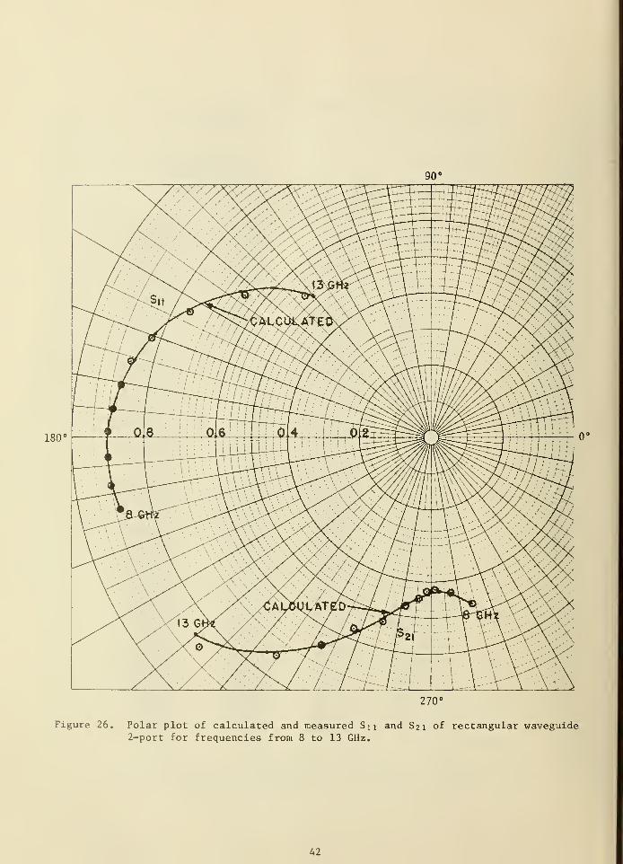
180'
270°
Figure 26. Polar plot of calculated and measured S i i and S21 of rectangular waveguide2-port for frequencies from 8 to 13 GHz.
42
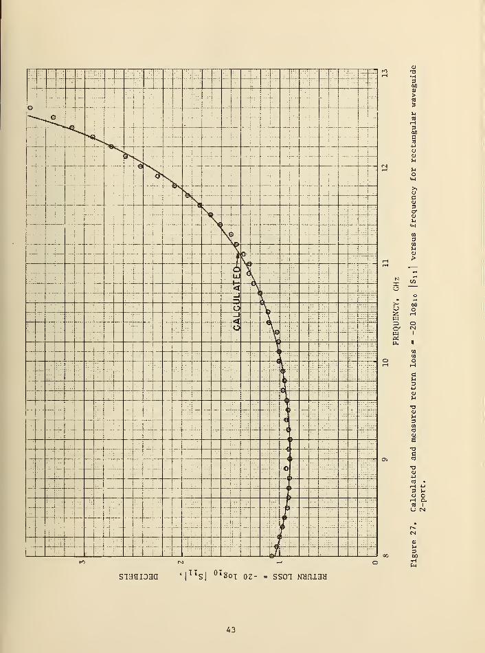
!l: -; -mm
i
iiiijiiii
[
IS|||
1
4r
m liip i
'iffj
'
i 1
... i.._
ji
i t|b©t
r1
•
"i
"
j
_. j: ... —i
—
-r-i
r r"i
-. J ...]_:. _ ..,...-
i .__L: ! _. . :j_... :-':-1
1
i
. s_j 4- j -|-i
.1.. - 4 :
.—.L .
i
;
i
i-i.
----- i
.
;
hi
:
- r-j
i
1
i
.._:|
1.
i
,.| ^ -r
4 -;
j-
i
....j_. "\'"~
K :
_ .j
—
4- —-1 - ..J[L.L
j
i. .::|: i
^=|=::
i"
1
i
•
""j
!
i_. - 1
—
'
|
1
i
i
IxJ
'.:!':::•
|!
; m±;
i
..Ii
:
l
'.
1
: 1.
1
i
i
"i
I
1 -
f''
'<i
::.!: : j ."1.
.
i: !\:i
:
1- . :(:. -
- j: i1
r 1
. 1
•*?:L:: .{.":=
-j
j
-; l_l :::
| j
m 1
i O \j,.|.
1:-
: i
1
':
i1
1
::: :\ I. .j
—i
'
!
1
1
:
::|:
1 X [- iii=
- !•• i'c\' :
i:-:z.
:::: !.. :
| ;
-
Ii
;
:
'
i !- k -1 : -
1
:;;:-. : :r::|~:;
;;1
.;[_ i ":: j 1 ;
"ri:r
1
1— —{-- i. i| 1
!
:::l"7:
;:::[.::: :]::
:::r:.: -:':
: .± .
I
i
-1 j _.. :l —I
!
—tHt -ii
1. —— ~-:~
:|
|-i — -
' — --- < Miili 1
"
i!
1
4~ ......-.W-m
'
—— - ;
i
:
-[
r _h ; -
|:
!
-
'
::: 1:
. ::
;
!
1
:
j: "
i :
1
: :
i:- i:::
l
1
-4- -:;
" ( '
i
:: i
|:
!
:
- r i
j jl... 1 1
:::k
i!.
'
:•' ij-
'
1
j
i
j:i| i
A;v=b
j
:;
l-l i.-,-j ::
'! :.'!
!! Pi
I T~ is ..,.!,,,
-M#i1
-I-1
miii
-'- 1-. .jiliiii
z&~- m Lii
-444-j--- IPI—
_
Xu
u2W
wOS
(U
•H3M0)
>
ca
360CCO
4-1
U<Ul-l
)-l
o
uc
Dcr0)
60O
OCN
I
u34-1
0)
<U!-<
3wCO
0)
e
s-3CU4-1
CO
rH3O
0)
M360•H
siaaiDaa iiTToi 01|
LLS|
UL Soi 0Z- SS01 NHfliaH
43
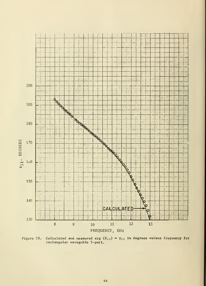
200
190
180
w 170
wQ
luO
150 —
140
130
1
.
:
:
—
1
: - 4i
I';T -'
i
-4-
•
•
I
'-
!
1 .:
: I .
"l
I
• ;:
; -|
T-
— '. :!
I -
I" '
i
: I -
!...
...\
S!
. |.:- I-
;
!
..::!:; . UM::
;
.I
i
i*:
I::!
:i: :
„ 1
• 1•
±-
i
'
!
: .
i
!.-:
|
. i
-"
•
i
. !
j§I
i
1
i
:
— —
-
-t
-
-:
;-:->-•
i
;
- --
i
... 1
•
:
j
'
1
LJj-i:
:
I
I . !
"I !
::{::::: i : :
••I--- .4-'.-
:
'
I
!:
ti-•• } \.j
';
'
I
VJ1
i
i •
i ^ ii :
I
•i
:
. y
1—
i
i
Y"\1
!
i.
ii A :i
:
l
1. ;•:.
i
•
'
: V
j
i
!
- • ._)
i
i•
i
'
;
i
I
i
'
1
r
i
no
1
: i
- !
1
1m |)|
i
--!-
il
'
*
i
s :
l
Y'
!
CAUI
Ate -ML-
- • .....
: i
;
J
t
•
I !l
!
!
|
i
•• • , |isi
' -IXii i
-
i ...,i..,: i i
.i. i:i;l , ,,,, v\
10 11 12
FREQUENCY, GHz
13
Figure 28. Calculated and measured arg (Sn) = tyu in degrees versus frequency for
rectangular waveguide 2-port.
44
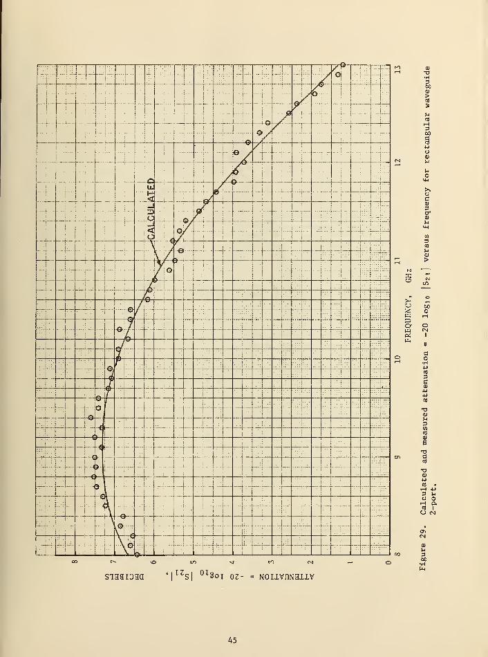
Jliiill
i
• Si1
4(5 -{--:| 1 "J" 1
i
'.:
i'
'
:!;•-
—\jr
i
4. :.
1
I
\
1
I
..[...1_ ......
1...-.
: ._- 1
- ...
;
v -j
• -i — -f-i ft
I „ ..._j. - ...!_.. - :._!_
h" ry-:
i
"! - !
1
r>
&s 1
;
! -
:
j.111
i
e / :--j— - —r r
<
-
:H'/ 1 a
.. j ;
'1
- -— _j
—
(... .4!
-: • ...4..—: "H
"'
[':::
-i-3: O
-p-J
- -
—,
—
1
r —i
—
.'::I i
1 ::i1-..
|
j
1i
1:: -] -
6 1 !
1 -1 -":.:•.'.:
•j
.:1
- f
1
"- ..... _l
....
:'
J .
'\Z7zi^-Z^~
.._L 1
:i::
J\
-
i
__!__ - -j~ /i ft
1
•'
!
'
ja i
1
i' : 1 _.
.
: :: (;.•..
':'- i
i. i
|
4.:•:]• !
.;::
l
: •''
i ::::!;:::
: i
/(T» i
""..
'
!
'.
i-
1
;
'"1 "
1
' n'
1
V.. . ...1 ...
:...p-::
1
- •
1i
,
1'....- -:
i **LZ 1
:i -l
:-r
!•- T \:~--
l:-:-
1
1
-4- _/j
'
.r .
i
. 1 .:;'
1 L •1
:
1
:
'
'
1
:..j
J t "! :|:
' r~
'] \f- 1
|;
::-pn \T 1 !
:~|~:
1 :: si:
lJ
€>4~i
...1- :
.1 .~"
- n :j
:
: l: :
r
— — ^ ft. i
...: .L !
ifi 1
11
1
.
1
: M'
1 '
—-j— i N"1
::
j
;
:;p|
::.
1 -1 I :
'
i
1:. "1 ':
— r—\—! 11
)
B '
r'lprr— j—
! ::
1
-
1
1
^__1 '..-
::--i-f:
X I;
h1
:.j :.:|
H j| ..:;_
.
:|-
I j'
.
I
—
-
--•'.[. ':.
1 ""p•'l::":
:
•
1
. !.' 1-
_....._:._:. -_
V\
1
1
" 4.
.
-':'(:- —-j---
1
— '
---!_!:
i
i—i
::| - -
: r : :::
»
—
i
i:-|
1"-
[r
-— i
. , ...1
.i—li_.
1!
1 .
j
1
_ifc1
...4_...
i
j
-'-I.
i_ -
1
"
. ..
_:'.L ..
i'
:!:.-.
.:. .
[,:> .
1
:
1
_'
^_VJ
£ i
1 •;! i
1. .:
X
u2PJXiO'pqPiP-,
siaaiDHa TZ,S|
0I Soi oz- = NOIIVnNSIIV
a)
•H3600)
H3W)
4-1
oai
n
o
>>oC<u
3a-
05
3CO
na)
>
00o
oCN
I
CO
3C<uuucfl
XIcu
U3COcd
<u
e
CCfl
XICU
•PCO •
iH 4J
3 MO Oh excfl IU CN
CN
a)n360•H
45
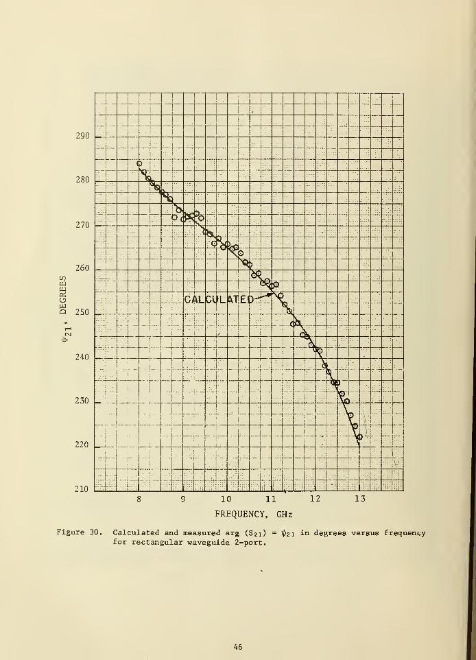
1
! 1
'
i—
,
290 ri
r .J _
J:
c ) — . — T— —280
'
i
- ::
11—
27(1^>C ;:.
;
i K 1
........
;
-i
•
- ]<•
--.i<3
>ro .;
260-1 >j
CO:. ::!:-:-
1-" "
-.i- __ V--:.:.
:•":
w ^L :!!:l;i:
!;i:;
OS\:
0?u *TF1 \Q
1
— —
-
- -- —Q 250
'i
1'
:t:.::
1 ri
: i
. ]...',
i—
i
:t.
:::-9-
'.-':
i
.:
|
:: - :
i
\_.-
.
!
240 : ::
:•:;::::!•::
\
i
yi — L__
i
'1 .-
-: r- 4-
-
1
_: !-j-
- -
i
-
- . .
i
i
i
1: _ -:.i
!
>'
!
'
230i
r. (•:::
!
:}--'
1
• ;_ J
B~ i
1:
I
1
- —[
-•: i •.!
...
v.urp
^_ !ii
220
i—i
i
— ;-- -
i
r i
... :j_i
' :
--'. — i --4t" _...
;
1
rr~i
—
--i
-i — - -—~- —M
.. .
-s-J fii IQJ
\-
1210 m ,: :•!:; ,
,
__.. t'i":| \V jfj
10 11 12
FREQUENCY, GHz
13
Figure 30. Calculated and measured arg (S21) =1^21 in degrees versus frequencyfor rectangular waveguide 2-port.
46
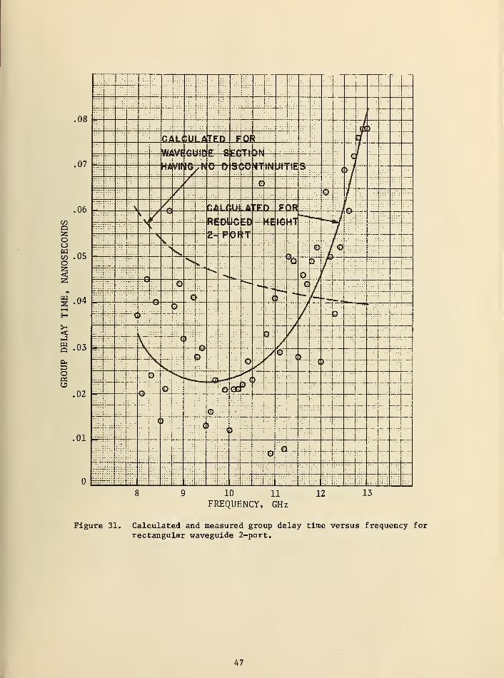
: :::!..'
1 T :;
i
;ii; :'T
—
:
;;::
i;;;::
i i: y:—
-
T-TT--r- -
OR:
1; 1
CJIL< JU -A TEJD FOf ?
:: WlVf A4 iiri P 8 Ff Tt ^W :::fj .
:.:
: —07
MUr
tu l/INSsf.
:" H£vWK^/N©~ U s<10 TTTTT iff|IES-
()/
:.Q —'
06 o Gfllif Ul A'FFY F<[>R r>
CO::::i::::
V::u—I __ Rfi04
O 1 Dp — 4€
\j
QO
::^ ...
i 1 j
::;:{: .:
14:
SH 2H r—!—
OrrV 1
o P&•
i — ..._42
to .05o
1
' !:""
s
_._: ... * >sN^ii
: :" ^D P LI i2g :::: • :
iraj^
:1
ol y
...r
.
. : : 1
-:z ™ :
:::;|;
1
1 :;:.t_._,
>
•=i_t4 _i_
.•j
::.:,::::
£ .04™.:
|;-;: j n <*: 1 .:
( 1
;
2 *u
h-
1
-!d
c
. ..j .
:
!
--:. i . .
.
-:- 'K / ;•- D
I. .
--" :
_:ii::H :':!
.
.
.
s(
in
1
]
1
'
'
Q ...L._...
... 1. :: -i —
S 03::;:|:
. -f— ;..._
:. I.:
Q ,uol| Ni — :-;-
1 w_ I
:
1
'::
... j:
i
•:
y ism 1
• r ..... i .
.
i
i
—
• 1.. .
Oh3 !/* : :
:
|:
Oerf
::::]. ~T'.'o
31
!§oP):
1
i
:i .
.:•'! :
•rfr.::-|
. :!
.02—
o-i'! :.•
:
_; '
-::-\... Jili::! -f.
i :
:
: ::|:
o
1'
j.
:_: j :
•
..:..
;|-
:
. .:!._:.
-;:!
•
'
i-
:
.1
I< > _
J. t ......... ~".;:.| ;;;.
:I:••
:.]•-:!. . :
:..|,.
.01"
:
i
'.I
:::i:
-— __]...__
;:!
Hrr
::-.:i::\
—-i—;;::|
—:L i --: r-
rH
--
... i.i
'
;4di£ -TV -'-
— 1
:::
::::!.-.::
::::::::!...._.
. 1 :\:~-
: ::]::
o:;::
t:—,tl,
:::: :::.;:.!
1 :;
:
iT:;|iij|
..?:
"ill _*i _..
9 10 11
FREQUENCY, GHz12 13
Figure 31. Calculated and measured group delay time versus frequencyrectangular waveguide 2-port.
for
47
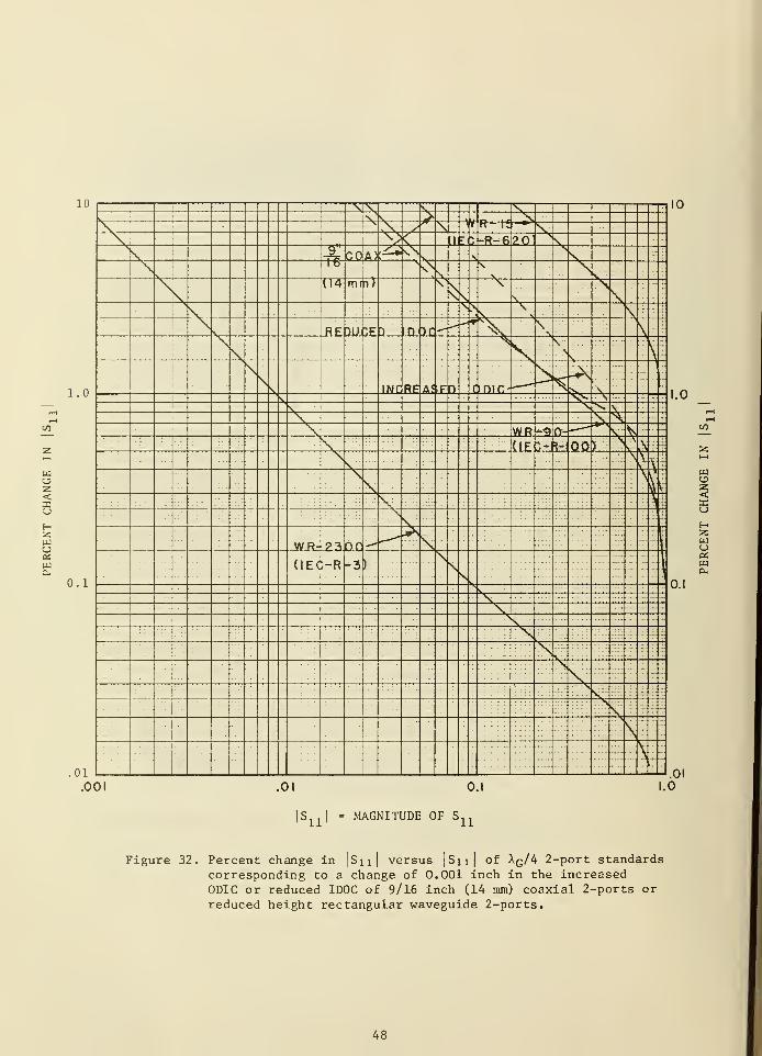
z
wZ<uHzw
xu \\ 's
V | \1
^ \ 1 V R— 1
1
r *
1\s
l\- •:-R-6 PO 1
its GOiA>,s±\\
v.
!1 o
.
VS*
Vv
U4 mrn; y\\
\V
\ > .
v.1 j
RF ">m if 1 mi">r* N\ \ \
\s,
n INT RF A?>F n time-
. . . >
^. \:"
: l
\v. \
^WR *fl 0- V(IF >l £: 00 >
\
PiV V
\\:
-S1 ;:
WR- ??\ CLO ""•*
i
(IEC)-n::::
-3 )
1
— -
: :
: : :
-'-:
E !
: i
....
' -
m
1.0
z
<u
zwu«wa.
0.1
.01
.001 .01 0.1 1.0
SI
= MAGNITUDE OF Sn
Figure 32. Percent change injS x l I
versus]S 1 1 |
of Xq/4 2-port standardscorresponding to a change of 0.001 inch in the increasedODIC or reduced IDOC of 9/16 inch (14 mm) coaxial 2-ports or
reduced height rectangular waveguide 2-ports.
48
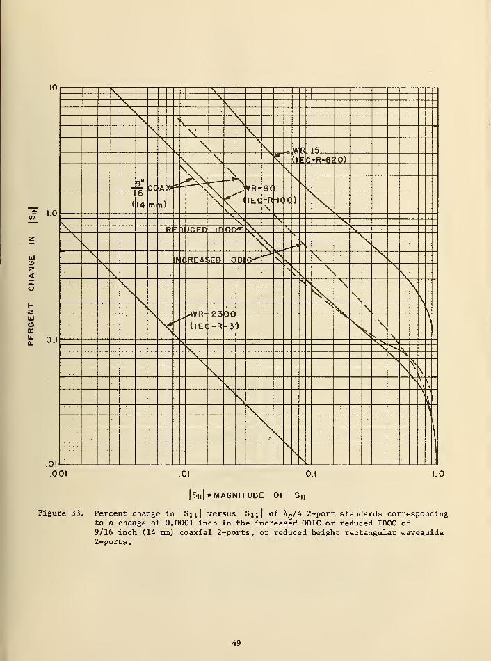
IVI
I \i
\j\v
X\ .- Wl*-IF>
\ (IF^C-R-62iO)v\ \
£ r,r A ^\VR- 9f i
,n'-°
(
b
14 m n)\N
( tEC -R\
-IC>0)
X VV \R r
lHiLEh ID 00* \N. Vz V
A> v \
mll\ CREAI>ED c Dl V \
z< \
k
X 'v
">>V \V \^WR- ??>00
^\
,:
UJo1Jj«
O.I
(IEC;-R -3 )
>^
\\ss \,N \.s
^^
V^
t
m.001 .01 0.1 1.0
|Su| MAGNITUDE OF S M
Figure 33. Percent change in |Su| versus |Sji| of Aq/4 2-port standards correspondingto a change of 0.0001 inch in the increased 0DIC or reduced ID0C of9/16 inch (14 mm) coaxial 2-ports, or reduced height rectangular waveguide2-ports.
49
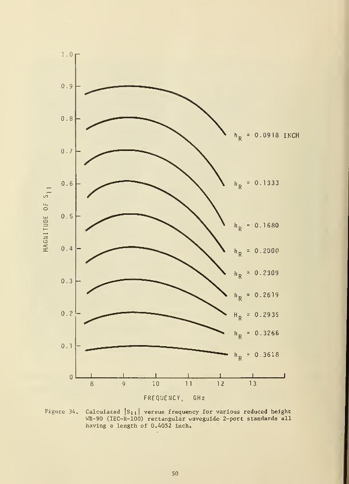
1 .Oi-
0.9
.:-: -
0.7
0.6
0. 5
0.4
0.3
0.2
0.1
hR
= 0.0918 INCH
0.1333
hR
= 0.1680
hR
- 0.2000
hR
= 0.2309
hR
- 0.2619
HR
= 0.2935
hR
= 0.3266
h D= 0.3618
K
10 1
1
12 13
FREQUENCY, GHz
Figure 34. Calculated |Su| versus frequency for various reduced heightWR-90 (IEC-R-100) rectangular waveguide 2-port standards all
having a length of 0.4052 inch.
50
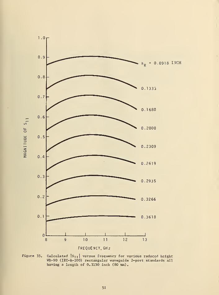
1 .On-
to
Li-
o=>
hR
= 0.0918 INCH
0.1333
0.1680
0.2000
0.2309
0.2619
0.2935
0.3266
0.3618
FREQUENCY, GHz
Figure 35. Calculated|S x x I
versus frequency for various reduced heightWR-90 (IEC-R-100) rectangular waveguide 2-port standards allhaving a length of 0.3150 inch (80 mm).
51
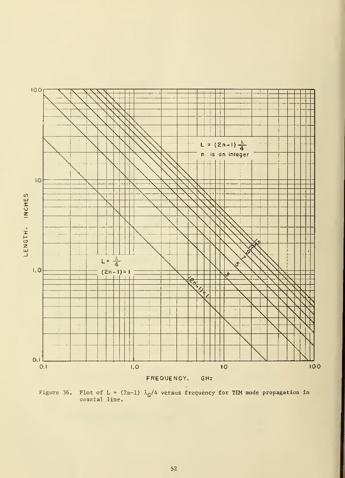
100
UJ
Io
XH
zUJ
100
FREQUENCY, GHz
Figure 36. Plot of L = (2n-l) AG/4 versus frequency for TEM mode propagation in
coaxial line.
52
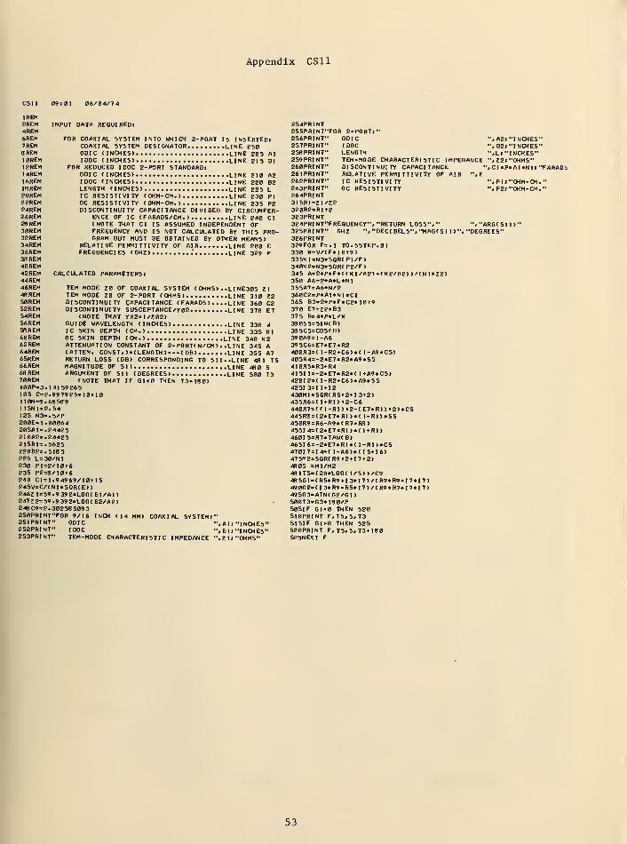
Appendix CS11
CSII 09101 06/04/7 4
REM2REM INPUT DATA REQUIRED!4REM6REM FOR COAXIAL SYSTEM INTO WHICH 2-PORT IS INSERTEDl7REM COAXIAL SYSTEM DESIGNATOR LINE 2508REM ODIC (INCHES) LINE 20S AlI0REM IDOC (INCHES) LINE 2IS Bl12REM FOR REDUCED IDOC 2-PORT STANDARD!14REM ODIC (INCHES) LINE 210 A2I6REM IDOC (INCHES) LINE 220 B218REM LENGTH (INCHES) LINE 225 L20REM IC RESISTIVITY (OHM-CM.) LINE 230 PI22REM OC RESISTIVITY (OHM-CM.) LINE 235 P224REM DISCONTINUITY CAPACITANCE DIVIDED BY CIRCUMFER-26REM ENCE OF IC (FARADS/CM.) LINE 240 CI28REM (NOTE THAT CI IS ASSUMED INDEPENDENT OF30REM FREQUENCY AND IS NOT CALCULATED BY THIS PRO-32REM GRAM BUT MUST BE OBTAINED BY OTHER MEANS)34REM RELATIVE PERMITTIVITY OF AIR LINE 200 E36REM FREQUENCIES (GHZ) .' LINE 329 F38 REM40REM42REM CALCULATED PARAMETERS!44REM46REM TEM MODE Z0 OF COAXIAL SYSTEM ( OHMS) . .LI NE305 ZI4BREM TEM MODE Z0 OF 2-PORT (OHMS) LINE 310 Z250REM DISCONTINUITY CAPACITANCE ( FARADS) ... .LINE 360 C2^2REM DISCONTINUITY SUSCEPTANCE/Y02 LINE 370 E7S4REM (NOTE THAT Y02=l/Z02>56REM GUIDE WAVELENGTH (INCHES) LINE 330 WS8REM IC SKIN DEPTH (CM.) LINE 335 Kl60REM OC SKIN DEPTH (CM.) LINE 340 K262REM ATTENUATION CONSTANT OF 2-P0RT( N/CM) . .L I NE 345 A64REM (ATTEN. CONST. )«(LENGTH ) (DB> LINE 355 A765REM RETURN LOSS (DB) CORRESPONDING TO SI 1..LINE 48 1 T566REM MAGNITUDE OF Sll LINE 480 S68REM ARGUMENT OF Sll (DEGREES) LINE S00 T370REM (NOTE THAT IF Gl<0 THEN T3*180>100P=3. 141 59265105 C=2.997925«10M0110N=8.68 5891ISN1 = 2.54125 N3=.5/P200E=1 .00064205AI=. 24425210A2=. 24425215B1=.5625220B2=.5I8 5
225 L=30/N1230 Pl=2/10t6235 P2=8/I0t6240 01=1.94969/ I0t 1
5
245V=C/(N1«SQR(E>)246Z l = 59.9 39 2*L0G(BI/AI>247Z2=59.9392*L0G( B2/A2)248 C9=2. 30258 5093250PRINT"FOR 9/16 INCH (14 MM) COAXIAL SYSTEM!"251PRINT" ODIC ". Al» "I NCHES"252PRINT" IDOC ". Bl J "INCHES"253PRINT" TEM-MODE CHARACTERISTIC IMPEDANCE ", Z 1 1 "OHMS"
254PRINT255PRINT"FOR 2-PORTl 1
ODICIDOCLENGTHTEM-MODE CHARACTERISTIC IMPEDANCEDISCONTINUITY CAPACITANCE "
RELATIVE PERMITTIVITY OF AIR ", E
IC RESISTIVITYOC RESISTIVITY
256PRINT"257PRINT"258 PRINT"259PRINT"260PRINT"26IPRINT"262PRINT"263PRINT"264PRINT3ISRI=Z1/Z2320R2=R1 «2323PRINT324PRI NT-FREQUENCY". "RETURN LOSS"."325PRINT" GHZ ". "DEC! BELS". "MAG( S 1 I >
326PRINT329F0RF=.l TO.5STEP.01330 W=V/(F*l0t9>335KI=N3«SQR(PI/F>340K2=N3«SQR(P2/F)345 A=2«P«F«((K1/A2)-KK2/B2))/(N1*Z2)3S0 A6=2»A*L»NI355A7=A6*N/2360C2=P*AI*N1«C1365 B3=2*P»F«C2*10»9370 E7=Z2«B3375 B=4«P»L/W38 0SS=SIN(B>385CS=COS(B)39 0A9=I-A6395C6=E7«E7«R2400R3=( l-R2+C6)»( l-A9*C5)405R4=-2«E7*R2«A9«SS410R5=R3+R44151 l =-2*E7*R2«( 1*A9»C5>4201 2=( l-R2»C6)*A9*S542513=1 l + IS430MI=SQR(R5t2*I3»2)435R6=( I*R1 > t2-C6440R7=(( l-Rl)t2-(E7*RI)t2)«C5445R8 = (2«E7«R1 )»( 1-R1)«S5450R9 =R6-A9«(R7»R8 >
455I4=(2*E7«R1>*( 1*R1>460I5=R7«TAN(B)465I6=-2*E7»R1«( l-RI)*CS4701 7=1 4+( 1-A6)*(I5+I6>475M2=SQR(R9»2*I7l2)48 0S =MI/M24BIT5=(20«LOG( 1/S))/C948 5G1 = (R5*R9*I3*I7)/(R9«R9+I7*I7>490GB=(I3*R9-R5*I7)/(R9*R7*I7«I7)49 5G3=ATN(G2/G1 )
500T3=G3*I80/P505IF Gl<0 THEN 520510PRINT F.T5. S. T3515IF Gl>0 THEN 525520PRINT F.T5.S»T3*180525NEXT F
•.A2l"INCHES"'. B2l "INCHES"'.L! "INCHES"".Z2l "OHMS"CI«P»AI*NI»"FARADS
•»P1I "OHM-CM."-.P2( "OHM-CM."
"."ARG(SI I)'•DEGREES"
53
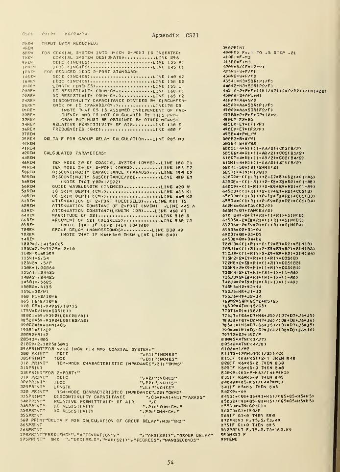
cs2i p°:v* 06/04/74 Appendix CS21
2REM INPUT DATA REOUI ftED:
4REM6REM FOR COAXIAL SYSTEM INTO WW I CH 2-P0hT IS INSERTED:7REM COAXIAL SYSTEM DESIGNATOR LINE 29 6
*RE"1 ODIC (INCHES) LINE 135 AlI0REM I DOC (INCHES) LINE 145 Bl
12REM FOR REDUCED I DOC 2-PORT STANDARD:14REM ODIC CINCHES) LINE 140 A2I6REM I DOC (INCHES) LINE 150 B218REM LENGTH (INCHES) LINE 1 55 L20REM IC RESISTIVITY (OHM-CM.) LINE 160 PI22REM OC RESISTIVITY (OHM-CM.) LINE 165 P224REM DISCONTINUITY CAPACITANCE DIVIDED BY CI RCUMFER-26REM ENCE OF IC (FARADS/CM.) LINE170 C52RREM (NOTE TWAT CS IS ASSUMED INDEPENDENT OF FRE-30REM OUENCY AND IS NOT CALCULATED BY THIS PRO-32REM GRAM BUT MUST BE OBTAINED BY OTHER MEANS)34REM RELATIVE PERMITTIVITY OF AIR LINE 130 E36REM FREQUENCIES (GHZ) LINE 400 F
37 REM3«REM DELTA F FOR GROUP DELAY CALCUL ATI ON. . .LI NE 205 M340REM41 REM42REM CALCULATED PARAMETERS:44REM46REM TEM MODE Z0 OF COAXIAL SYSTEM (OHMS). .LINE 180 Zl48REM TEM MODE Z0 OF 2-PORT (OHMS) LINE 185 Z250REM DISCONTINUITY CAPACITANCE ( FARADS) ... .LI NE 190 C252REM DISCONTINUITY SUSCEPTANCE/Y02 LINE 480 E754REM (NOTE THAT Y02=l/Z02)56REM GUIDE WAVELENGTH (INCHES) LINE 420 W53REM IC SKIN DEPTH (CM.) LINE 435 Kl60REM OC SKIN DEPTH (CM.) LINE 440 K261REM ATTENUATION OF 2-PORT ( DECI BELS) . . . .LI NE 8 I 1 T562REM ATTENUATION CONSTANT OF 2-PORT (N/CM) .LINE 445 A63REM ATTENUATION CONSTANT*LENGTH (DB)....LINE 460 A764REM MAGNITUDE OF S2 1 LINE 810 S66REM ARGUMENT OF S21 (DEGREES) LINE 8 60 T368REM (NOTE THAT IF G1<0 THEN T3+130)70REM GROUP DELAY (NANOSECONDS) LINE 8 30 K972REM (NOTE THAT IF K6*K5>0 THEN LINE LINE 8 40)7 4REM100P=3. 14159265105C=2.997925*10tl0I10N=8.68 58 91 I5N1 = 2.54125N3= .5/P130E=1. 00064135A1=. 24425I40A2=.24425I45B1=.5625I50B2=.5185155L=30/N1160 Pl=2/10t6165 P2=8/10t6170 C5=l. 94969/1 0t 15175V=C/(N1*SQR(E>>18 0Z1=59.9 39 2*LOG(BI/A1)185Z2=59.9392*L0G( B2/A2)190C2=P*A1*NI«C5195R1=Z1/Z2200R2=Rlr2205M3=.005210C9=2. 30258 5093296PRINT"F0R 9/16 INCH (14 MM) COAXIAL SYSTEM:"300 PRINT" ODIC ".All "INCHES"305PRINT" I DOC ". Bl» "I NCHES"310 PRINT" TEM-MODE CHARACTERISTIC IMPEDANCE". Z 1» "OHMS"315PRINT318PRINT"FOR 2-PORT:
"
319 PRINT" ODIC "»A2» "INCHES"320PRINT" I DOC ". B2l "INCHES"325PRINT" LENGTH ".Ll "I NCHES"330 PRINT" TEM-MODE CHARACTERISTIC IMPEDANCE". Z2l "OHMS"335PRINT" DISCONTINUITY CAPACITANCE ", C5*P«A1*N1 1 "FARADS"340PRINT" RELATIVE PERMITTIVITY OF AIR ",
E
345PRINT" I C RESISTIVITY ". P 1 J "OHM- CM. "
350PRINT" OC RESISTIVITY ", P2l "OHM-CM.
"
355PRINT360 PRINT"DELTA F FOR CALCULATION OF GROUP DELAY".M3> "GHZ"365PRINT366PRINT37 0PRI NT"FREOUENCY". "ATTENUATI ON", " ", "ARG( S2 1
) ". "GROUP DELAY*37 SPRINT" GHZ ". "DECI BELS". "MAG( S2 1
) ". "DEGREES". "NANOSECONDS"
380PRINT400FOR F=.l TO .5 STEP .01410F1=F-M341SF2=F*M3420W=V/(F*10t9)425W1=W*F/F1430W2=W*F/F2435K1=N3*S0R(P1/F)440K2=N3*SOR(P2/F)445 A=2*P*F*( (K1/A2)+(K2/B2) )/(Nl*Z2)450A6=2»A*L*N1460A7=A6»N/2465A8=A6*S0R(F1/F)470A9=A6*SGR(F2/F)47 5B5=2*P*F*C2*10t94S0E7 = Z2*B54S5E8=E7*(F1/F)49 0E9=E7*(F2/F)495B=4*P*L/W500B3=B*W/W1505B4=B*W/W2600Q1=4»RI«( l-A6/2)*C0S(B/2)60586= 4*R1*( l-A8/2)*C0S(B3/2)610Q7=4*R1«( l-A9/2)*C0S(B4/2)615H1=4*RI*( l-A6/2)*SIN(B/2)620M1=SQR(G1 »2+Hl t2)625D1=ATN(H1/Q1>63002=- (( 1-R1) t2-E7»E7*R2)*( 1-A6)63508 = - (( 1-R1 ) t2-E8*E8*R2)*( 1-A8)64009=- (( 1-R1) t2-E9*E9*R2>*( 1-A9)64503= (( l+RIl t2-E7*E7«R2)»C0S(B)650D3=(( 1+R1) t2-E8*E8*R2)«C0S(B3)655D4=(( 1+RI ) t2-E9*E9*R2)*C0S(B4)660H6=G6*TAN(B3/2)665H7=Q7*TAN( B4/2)670 Q4=-2*E7*R1»( 1*R1)»SIN(B)67 5D5=-2*E8*R1*( 1 + RI )«SIN( B3)68 0D6*-2*E9*R1*< 1+RI )*SIN< B4>68 5Q5=Q2+Q3*Q469 007= 08 +D3+D569 5D8 = Q9*D4*D6700H3=(( 1+Rl)t2-E7*E7«R2)*SIN(B>705JI=(( 1*R1) t2-E8*E8*R2)*SIN(B3)710J2=<( l + Rl > »2-E9*E9*R2>*SIN(B4)7I5H2=2*E7*RI«( l+Rl )+COS(B)720H8=2*E8*RI*(1+R1)*COS<B3>725H9=2*E9*R1*( 1+RJ )*COS( B4>730H4=2*E7*R1*(R1-1>«( 1-A6)735J3=2*E8*RI*(R1-1>«< 1-A8)740J4=2«E9*R1*(R1-1)*C I-A9>745H5=H2*H3*H4750J5=H8+J1*J375SJ6=H9*J2+J4760M2=SQR(Q5t2+H5t2)765D2=ATN(H5/05)770TI=D1*180/P775J7=(Q6*D7*H6»J5)/<D7*D7*J5»J5)78 0J8 = (Q7*D8+H7*J6)/(D8*D8*J6*J6)78 5K3=(H6*D7-06*J5)/(D7*D7*J5*J5>790K4=(H7*D6-O7*J6)/(D8«D8*J6*J6)795T2=D2*180/P800K5=ATN(K3/J7)805K6=ATN(K4/J8)8 10S=MI/M28 1 1T5=(20*LOG( 1/S))/C9815IF (K6«K5)»2<1 TH EN 8 40820IF K6*K5<0 THEN 830825IF K6*K5>0 THEN 8408 30K9=(K5+P-K6)/(4«P«M3)835IF K6«K5<0 THEN 8 458 40K9=(K5-K6)/(4*P*M3)841IF K5>K6 THEN 8 45842K9=-K98 45Gl=(01»05*Hl*H5)/(05»05+H5*H5)8 50G2=(H1*Q5-OI»H5)/(Q5*O5*H5*H5)855G3=ATN(G2/GI
)
860T3=G3»180/P865IF G1<0 THEN 880870PRINT F.T5.S.T3.K9875IF G1>0 THEN 88 5
880PRINT F.T5.S. T3+18 0.K988 5NEXT F999END
54
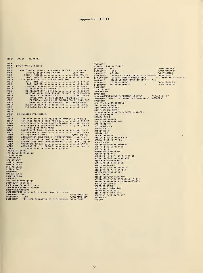
Appendix ICS11
!CSI I 03:35 06/07/74
I REM2REM INPUT DATA REQUIRED:4REM6REM FOR COAXIAL SYSTEM INTO WHICH 2-PORT IS INSERTEDl7REM COAXIAL SYSTEM DESIGNATOR.,- LINE 250RREM ODIC (INCHES) » LINE 205 AlI0REM IDOC (INCHES) LINE 215 HI
I2REM FOR INCREASED ODIC 2-PORT STANDARD:I4REM ODIC (INCHES) LINE 210 A£I6REM IDOC (INCHES) LINE 220 B2IHREM LENGTH (INCHES) i. LINE 225 L20REM IC RESISTIVITY (OHM-CM.) LINE 230 PI
22REM OC RESISTIVI'TY (OHM-CM.) LINE 235 P224REM DISCONTINUITY CAPACITANCE DIVIDED BY CIRCUMFER-26REM ENCE OF OC (FARADS/CM.) LINE 240 CI28REM (NOTE THAT CI IS ASSUMED INDEPENDENT OF30REM FREOUENCY AND IS NOT CALCULATED BY THIS PRO-32REM GRAM BUT MUST BE OBTAINED BY OTHER MEANS)34REM RELATIVE PERMITTIVITY OF AIR LINE 200 E
36REM FRECUENCIES (GH7) LINE 329 F
38 REM40 REM42REM CALCULATED PARAMETERS:44REM46REM TEM MODE 70 OF COAXIAL SYSTEM ( OHMS) . .L I NE305 71«REM TEM MODE 70 OF 2-PORT (OHMS) LINE 310 7250REM DISCONTINUITY CAPACITANCE ( FARADS )... .L I NE 360 C252REM DISCONTINUITY SUSCEPTANCE/Y 02 LINE 370 E754REM (NOTE THAT Y02=l/702>56REM GUIDE WAVELENGTH (INCHES) LINE 330 W53REM IC SKIN DEPTH (CM.) LINE 335 Kl60REM OC SKIN DEPTH (CM.) LINE 310 K262REM ATTENUATION CONSTANT OF 2-P0RT( N/CM) . .L I NE 345 A64REM (ATTEN. CONST .) *(LENGTH > (DB) LINE 355 A765REM RETURN LOSS (DB) CORRESPONDING TO SI I. .LINE 48 1 T566REM MAGNITUDE OF Sll LINE 430 S6RREM ARGUMENT OF Sll (DEGREES) LINE 500 T370REM (NOTE THAT IF GK0 THEN T3-MS0)I00P=3.I41 59265105 C=2.99792S«1 0110110N=f?.6KS«9I1SN1=2.54125 N3=.S/P200E=1 .00064205AI*. 24425210 A2=.26S1215PI=.S625220B2=BI225 L=l I. H 1 1
230PI=R/I0»6235P2=PI240 Cl=.569295/I0»15245V=C/(N1«S0R(E) )
2467 1=59.9 39 2«LOG( BI/AI)24772= 59. 9392«L0G( B2/A2)243 C9 = 2. 30258 5093250PRINT"FOR 9/16 INCH (14 MM) COAXIAL SYSTEM:"251PRINT" ODIC ".All "INCHES"252PRINT" IDOC ", Bl I "INCHES"253PRINT" TEM-MODE CHARACTERISTIC IMPEDANCE ",7ll"OHMS"
254PRINT255PRINT"F0R 2-PORT:'256PRINT" ODIC
tDOCLENGTHTEM-MODE CHARACTERISTIC IMPEDDISCONTINUITY CAPACITANCE
RELATIVE PERMITTIVITY OF AIRIC RESISTIVITYOC RESISTIVITY
"RETURN LORS"»"DECIBELS". "MAG( SI 1
)'
2S7PRINT"25« PRINT"259PRINT"260 PRINT261PR1NT"262PRINT"263PRINT"264PRINT31 5RI=71/72320R2=RI t2323PRINT324PRINVFREQUENCY'325PRINT" GH7 ".
326PRINT329 FOR F=. 1TO.5STEP.0I330 W=V/(F«l0t9)335K1=N3*SQR(PI /F>340K2=N3*SOR(P2/F>34 5A=2»P*F«((KI/A2)*(K2/B?))/(NI«72>350 A6=2»A«L*N135SA7=A6*N/2360C2=P«BI«N1*CI365 B3=2«P«F«C2» I0f9370 E7=72«B3375 B=4*P»L/W3R0S5=SIN(B)3«5C5=COS( P)
390A9 = 1-A639SC6=E7«E7«R2400R3=( 1-R2»C6)*( I -A9«C5)40SR4=-2«E7*R2«A9*S54I0R5=R3*R44151 l = -2«E7*R2«( l*A9»CS)420I2=( l-R2*C6)«A9*S542513=1 1+12430MI=SOR( R5i2*I 312)435R6=( I »RI ) t2-C6440R7=(( l-RI)t2-(E7»RI)t2)«C5445R3=(2«E7*RI)«(1-R1)*SS450R9=R6-A9«(R7-fR<?>455I4=(2«E7*R1 )*( 1»RI )
4601 5=R7«TAN( B)
4651 6=-2«E7*Rl«( 1-R1)*C54701 7= I 4*
(
l-A6>«( I 5*16)47 5M2=SBR(R9 t2+I7tg)4R0S =MI/M24R1T5=(20«LOG( l/S> )/C94R 5G I = ( R5* R9 I 3« I 7 > / ( R9« R9 I 7« I 7 >
49 002= ( I 3*R9-R5«I 7)/( R9«R9»I7«I7)49SG3=ATN(G2/G1 )
500T3=G3*I30/P505IF Gl<0 THEN 520510PR1NT F.TS.S.T35151F Gl>0 THEN 525520PRINT F,T5,S,T3-H30525NEXT F
999END
. A2l "INCHES', B2l "INCHES'»Ll "INCHES".72) "OHMS"CI«P*B1«NI) ' FARADS
,P1 1 "OHM-CM,, P2l "OHM -CM.
"ARG(SI I
3REES"
55
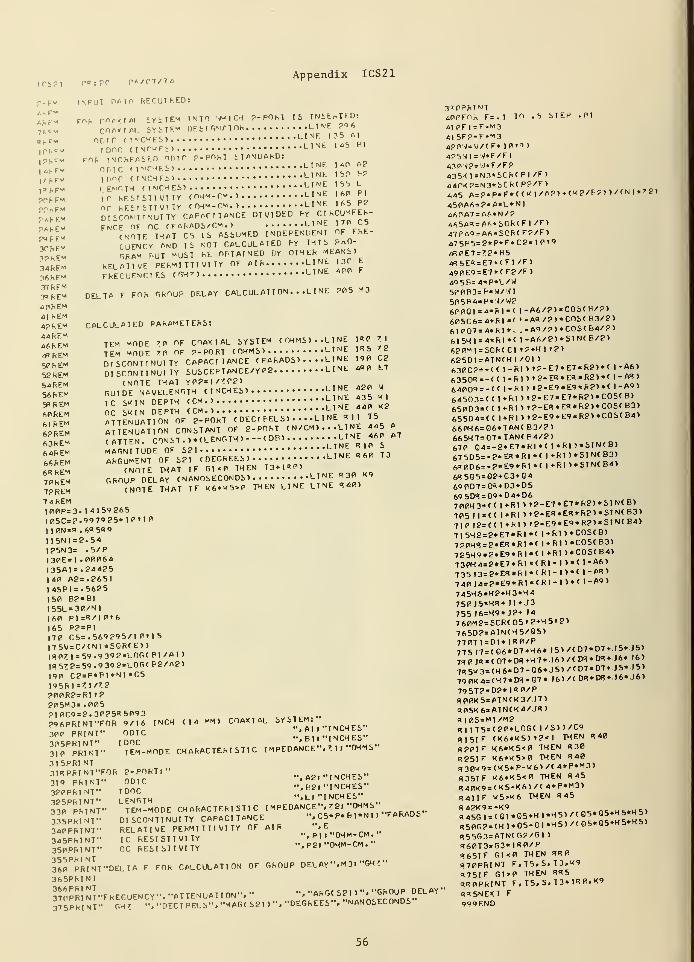
Appendix ICS21
p-F* INFUT DATA RECUTRED:
fery FCR rnpXIAl iYiTE-< INTO WICH ?-POhl IS INSERTED:
Sfm COITAL SYSTEM DESIGNATOR ^^A,ODIC (INCHES, LINE 135 Al
,n.r- rone unchesi line ,a ^
1?HF « F«f -NCRFASF.D nr; tr p-PORT iTANDARDs
MKFm ODIC (INCHES, LINE?
I^F- rDor (INCHES, L NE 50 b?
,.MP LENGTH (INCHES, LINE 5b L
p(4m »C RESISTIVITY C0KM-CM.1 L Nt 60 P.
POKFM n r RESISTIVITY (OHM-CM.) LIKE H5 Pd
P4REM DISCONTINUITY CAPACITANCE DIVIDED BY CIRCUMFEh-
P,cu EM FNCE OF OC (FARADS/CM., LINE I f»
~L CNOTE THAT C5 IS ASSUMED INDEPENDENT OF FRE-
3PKEM CUENCV AND lb NOT CALCULATED BY THIS FkO-
*S ^»M ™* "UST RE OBTAINED BY «"»««««»_3^EM RELATIVE PERMITTIVITY OF AIR LINE 130 E
36hEM FREQUENCIES (GH»> LINE 4PP
£r"e* DELTA F FOK GROUP DELAY C ALCUL AT I ON . . .L I NE BOS M3
4PREM41 REM4PREM CALCULATED PARAMETERS:
""em TEM MODE 70 OF COAXIAL SYSTEM (OHMS*. .LINE JR**l
'„„ tfm MODE 'P OF P-PORT (OHMS) LINE IR5 ^" . DISCONTINUITY CAPACITANCE ( FARADS, ... .L I NE ,9, C2
52KEM DISCONTINUITY SUSCEPT ANCE/Y 0? LINE 4« E7
S4REM (NOTE THAT Y0?=l/?P?>
l^REM GUIDE WAVELENGTH CINCHES, ^ W
S9REM IC SKIN DEPTH (CM., L NE 43b
Af,REM OC SKIN DEPTH (CM., ."lU =.T tVMfcEM ATTENUATION OF P-PORT ( DECI PELS , . • • -L I NE R 1 I T5
6PREM ATTENUATION CONSTANT OF P-PORT < N/CM , . . .L I NE 445 A
63REM (ATTEN. CONST ., .(LENGTH ,—
( DB, » » « "64REM MAGNITUDE OF SP1 L ni >'
6AREM ARGUMENT OF SSI (DEGREES, LINE R 60 T3
6RREM (NOTE THAT IF GXP THEN T3+1R0)
70REM GROUP DELAY (NANOSECONDS, LINE R 30 K9
72REM (NOTE THAT IF K6*K5>0 THEN LINE LINE R40)
74REMI00P=3. 1 41 59P65|05C=2.997925*10Mfl1 1 0N = « . 6R5H9
I 1SN1 = 2.54125N3= .5/P1 30E= I .00064135A1=.244P5140 A2=.2651145B1=.5625ISO BP=B1I55L=30/N1160 PI=R/I0t6165 PP=PI170 C5=. 569295/1 0'1S
175V = C/(N1 *SQR( E, ,
1HP!7 1 = 59.9 39P«L0G( PI/AI ,
IR57?=59.9 39 2*L0G(FP/A2,190 C2=P*B1*NI *C519SRI=7|/7??00R?=R1 t?
20SM3= .005?|0C9=2.30?SRS093P96PRTNVF0R 9/16 INCH ( I 4 MM ) COAXIAL SYSTEM.
300 PRINT" ODIC••; p,! "INCHES"
3lTpRINT" ^EM-MODE CHARACTERISTIC I MPEDANCE". Z 1 ."OHMS"
31 5PRINT3|RPRINT"FOR P-PORT:"
A2. "INCHES"3,9 PRINT" ODIC
..'feP •• NCHES"3P0PR.NT" 1DOC
..'"f"INCHES"
SSPJKJt-
LETEM
T
-MODE CHARACTERISTIC IMPEDANCE-.J8.-0HMS-,335PRINT" DISCONTINUITY CAPACITANCE ". C5«P* E) I *N
II FARAUS
340PRINT" RELATIVE PERMITTIVITY OF AIR '* E„nuM rM ..
345PRINT" IC RESISTIVITY.. 'pp Uhm CM "
350PRINT" OC RESISTIVITY "•Ml OHM-CM.
360PPRi'nT"DELTA F FOR CALCULATION OF GROUP DELAY". M3l "GH I"
365PRINT
37CPr'inT"FRECUENCY". "ATTENUATION". " ". "ARG( S2I> ". "GROUP DELAY
375PRI NT" GH 7 ", "DEC! PELS". "MAGC SP 1, ". "DEGREES". "NANOSECONDS"
TO .S STEP .01
(KP/PP, >/(N|*72,
3"=!0PRINT
4P0FOR F = . 1
^1 0F 1 = F-"3415F?=F+M34?(vj = V/( F* 1 0i9 ,
425VM = W*F/FI430H?=W«F/FP435K1=N3*SCR(P1/F,440K?=N3*SCR(PP/F,445 A=P*P*F*( (K 1 ZAP,45PA6=?«A«L«N146PA7=A6»N/P4 ftSAR=A6.S0R(Fl/F,47(?A9 = A6*S0R(F?/F,475PS=P*P*F*CP* 1 0»9
4R0E7 = 7?*R54R5E* = E7*(F|/F>49PE9=E7*(F?/F>4Q5P=4*P*L/W500B3=B*W/.V15P5P4=B*W/W26PPI01 = 4«R1*( l-A6/?,*COS(B/P,605C6=4*R1*( i-AS/?,*COS(B3/P,
61P07=4*R1*. .-A9/P,*C0S(B4/P,
61 5H)=4*R1*( 1-A6/?,*SIN(B/P,6P0M1=SCR(CI tP+Hl t?,
625D1=ATN(H1/C1 ,
630G?=-(( 1-RI
,
»?-E7*E7*R2,*( 1-A6,
6350^ = -<< 1-Rl)t2-ER*ER*R2)*< 1 - AH
,
640Q9=-(( 1-RI, t2-E9«E9*R2,*( 1-A9,
64503= (( l*RI
,
t?-E7*E7«RP,*COS(B,
65003= (( 1+R1, »?-ER*E««RP>*COS(B3,
655D4=(( 1*R1>»2-E9*E9*R?,«C0S(B4,660H6=Q6*TAN(B3/P,665H7=07*TAN(B4/2,67 fl Q4=-2*E7*R1*( 1 * R I ,*SIN(B,
67SDS=-2*ES*RI*( 1 *R 1 , SI N( B3,
6H0D6=-P*E9*R1*C 1*RI ,*SIN(B4,6R5Q5=Q?*C3*C469007=0^+03+05695DH = 09 + D4+D6700H3=((1+RI,»?-E7*E7*RP,*S!N(B,705ll=<< l+RI)»2-ER*ER«R2)*SINtB3)
710J2=(( 1+R1,»?-E9*E9*R?,*SIN(B4,715H?=2«E7*RI*( l+R|,«C0S(B,7P0K9=?*EH*R1*( 1+RI »«C0S<B3>7P5H9=2*E9*R1*(I+R1,*C0S(B4,730H4=2*E7*R1*(R1-1>*< I-A6,
735 J3=2*ER*R1*(R1- !,*( I-AR)
740I4=2*E9*R1*(RI-1 ,«( I-A9,
745H5=H2+H3+H4750)5=HR+ 11+ J3
755 J6=H9+JP+ 14
760M2=SOR(O5tP+H5t2,765D?=ATN(H5/05,770T1=D1* 1R0/P77 5J7 = (G6«D7 + H6* J5, /( D7«D7+ J 5* J5>
7H0 JR = <07*DR*H7*.I6)/CDR*DR + .J6*.)6)
7R5K3=(H6«D7-Q6*J5,/(D7«D7+ J 5*151
79 0K4=(H7*DH-O7* J6> /< DR«DB+.J6* J6>
795T2=D?*1R0/P«00K5=ATN(K3/ J7,
R05K6=ATN(K4/.JR,R|0S=M1/M2Rl 1T5=(?0*LOG( 1/S,,/C9
R15IF (K6*K5,'2<1 THEN
R20IF K6*K5<0 THEN R 30
R25IF K6*K5>0 THEN R 40
R30K9=(K5+P-K6,/(4«P«M3,R35IF K6«K5<0 THEN R45C!40K9 = (K5-K6,/( 4*P*M3>
R41IF K5>K6 THEN R45
R45G1=(Q1*Q5+HI*H5,/(Q5«Q5+H5«H5,R50G?=(HI*O5-O1*H5,/(O5*Q5+H5«H5,R55G3=ATN(G?/G1
,
R60T3=G3*|R0/PR65IF Gl<0 THEN RR0R70PRINT F.T5.S.T3.K9R75IF G1>0 THEN RR
5
RR0PRINT F.T5.S.T3+IR0.X''R«5NEXT F
999END
R40
56
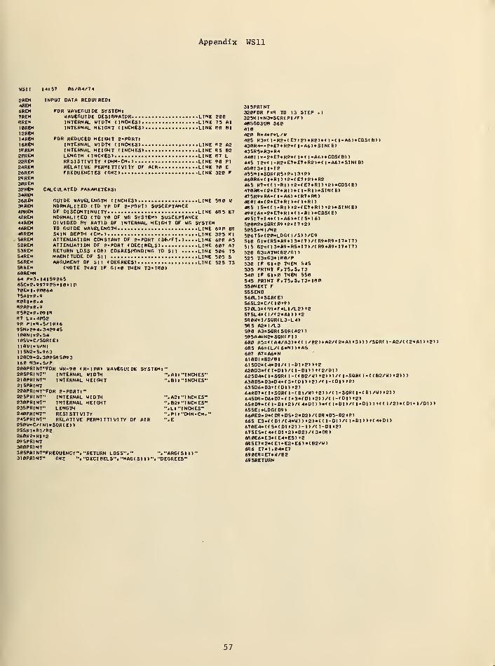
Appendix WS11
WS1I 14157 06/04/74
2REM INPUT DATA REOUIREDt4REM6REM FOR WAVEGUIDE SYSTEM!7REM WAVEGUIDE DESIGNATOR LINESREM INTERNAL WIDTH (INCHES) LINEI0REM INTERNAL HEIGHT (INCHES) LINE12REMI4REM FOR REDUCED HEIGHT 2-PORTlI6REM INTERNAL WIDTH (INCHES) LINEISREM INTERNAL HEIGHT (INCHES) LINE20REM LENGTH (INCHES) LtNE22REM RESISTIVITY (OHM-CM.) LINE24REM RELATIVE PERMITTIVITY OF AIR LINE26REM FREQUENCIES (GHZ)... LINE2* REM30REM32REM CALCULATED PAhAMETERSl34REM36REM GUIDE WAVELENGTH (INCHES) • LINE3KREM NORMALIZED (TO Yd OF 2-PORT) SUSCEPTANCE40REM OF DISCONTINUITY LINE42REM NORMALIZED (TO Y0 OF WG SYSTEM) SUSCEPTANCE44REM DIVIDED BY RATIO OF INTERNAL HEIGHT OF WG SYSTEM46REM TO GUIDE WAVELENGTH LINE4BREM SKIN DEPTH (CM.) LINE
. 50REM ATTENUATION CONSTANT OF 2-PORT ( DB/FT. > . . . .LINE52REM ATTENUATION OF 2-PORT (DECIBELS) LINES3REM RETURN LOSS (DB) CORRESPONDING TO SI I LINE54REM MAGNITUDE OF Sit LINE56REM ARGUMENT OF Sll (DEGREES) LINESRREM (NOTE THAT IF Gl<0 THEN T3»I30>60REMM64 PO.I4IS926S65C»2.997925«10t|070E*I.000647SAI=0.9R0BI=0.4R2A2«0.98SB2=0.09|f?R7 L>.40S290 P|sR.S/|0i69 5N* 2*4. 342945I00N1«2.54I0SV»C/SOR(E)II0V1=V/NIll5N2n5.963I20C9»2. 30253 S093160 N3=.5/P200PRINT"FOR WR-90 ( R- I 00) WAVEGUIDE SYSTEM!"205PRINT" INTERNAL WIDTH ",AI I "INCHES"2I0PRINT" INTERNAL HEIGHT ", Bl I "INCHES"21 SPRINT220PRINT"FOR 2-PORTt"225PRINT" INTERNAL WIDTH ",A2l "INCHES"230PRINT" INTERNAL HEIGHT "» B2) "INCHES"235PRINT" LENGTH "»LI "INCHES"240PRINT" RESISTIVITY ". PI I "OHM-CM.
"
24SPRINT" RELATIVE PERMITTIVITY OF AIR ". E2S0V«C/(NI*SOR(E>)S55RUBI/B2260R2iRlt229SPRINT300PRINT30SPRINT"FREGUENCY"# "RETURN LOSS"." ". "ARG( S I I
)
"
310PRINT" GHZ ". "DEC! BELS","MAG( SI I) "."DEGREES"
2007S AlRO Bl
R2 A215 B2<n l90 PI70 E
320 F
5B0 W
685 E7
69 ER
325 HI600 A5607 A7506 1550S S525 T3
315PRINT380FOR F«B TO 13 STEP .1
32SKI=N3«SGR(PI/F>405GOSUB 560410420 B«4*P*L/W425 R3=( l-R2*(E7»2)»R2)»( l-( l-A6)»C0S( B))430R4«-2«E7«R2*( l-A6)*SIN(B)43SR5=R3*R44401 1»-2«E7»R2*( l*C l-A6)*C0S(B>>445 I2=( 1-R2»E7«E7«R2>*( l-A6)«SIN(B)45013=11*12455MI=S0R(RSt2»|3«2)460R6i( l*RI
)
!2-(E7t2)«R2465 R7=(( l-RI) »2-(E7«RI) »8)»C0S(B)470RB = (2*E7«RI>«( I-R1)*SIN(B>475R9«R6-( 1-A6)«(R7»RB)480I4«(2*E7«RI )«( I»R1)43 S I5=((l-RI)»2-(E7«RI)t2)»SIN(B)490I6*-a«E7»RI*( I-R1)*C0S(B)49 51 7= I 4* ( l-A6)»(IS*I6)500M2=SGR( R9 «2*l 7 t2)50SS=MI/M2506T5=(20«LOG( 1/S) )/C9510 Gl=(R5«R9»I3«I7)/(R9«R9*I7«I7>515 G2»(I3«R9-RS«I7)/(R9*R9*I7«I7>520 G3=ATN(G2/GI
)
525 T3«G3»IB0/P530 IF Gl<0 THEN 545S35 PRINT F.T5.S.T3540 IF Gl>0 THEN 55054S PRINT F»T5.S»T3*|R0S50NEXT FS55END560LI°SGR(E)565L2=C/( I0t9)570L3=(NI*F«LI/L2) t2
575L4»( 1/(2*A1>> »2W0W=I/SQR(L3-L4)SB 5 A2«l/L3590 A3=SGR(SQR(A2>)S9SA4=N2*SQR(P1 >
600 A5=((A4/A3)«(( l/B2)*A2/(2»AI t3)))/SGR( l-A2/( (2«AI ) >2>)
605 A6=(L/(6»N))»A5607 A7=A6»N610DI=B2/BI6I5D2e(4»DI/( l-DI t2))t2620D3»(( l*DI)/( l-DI)) K2/DI)62504= ( l»SQR( l-((B2/W) t2)))/( |-SGR( l-((B2/W) »2>>>630D5=D3«D4»(3*(D1> t2)/( |-(D1) t2)
63SD6=D3t((DI) !2>640D73(|*SOR( l-(BI/W)»2)>/( l-SOR( l-(BI/W) »2>>645D8»D6«D7-( I +3»( Dl «2> >/( I -( D I > t2)65009= (( l-DI t2)/(4»DI))«(( l*DI)/( l-DI)) t(( l/2)»(DI*l/DD)65SE1»L0G(D9)660ES=2»(DB*D5*2«D2)/(DB*D5-D2t2)665 E3=((B!/(4*W>) t2>»(( 1-DI)/(1*DI))»(4«DI)670E4=((5*(Dlt2) )-!>/( l-DI t2>
67SE5=(4»(DI t2)»D2)/(3»D8)6B0E6«E3*(E4»ES> >2
6B5E7=2»(E1*E2*E6>«(B2/W>6X6 E7=1.04«E769 0E8 = E7*W/B2695RETURN
57
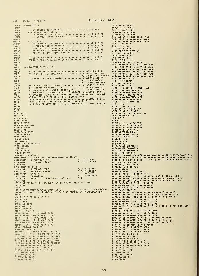
WS21 I Si 16 06/04/7 4 Appendix WS21
I0REM INPUT DATAiI2REMI3RE* WAVEGUIDE DESIGNATOR LINE 200
I4REM FOR WAVEGUIDE SYSTEMlI6REM INTERNAL WIDTH (INCHES) LINE 100 A|
IBREM INTERNAL HEIGHT (INCHES) LINE 105 Bl
20REM22REM FOR 2-PORTl?«REM INTERNAL WIDTH (INCHES) LINE I I A2
26REM INTERNAL HEIGHT (INCHES) LINE IIS B2
2RREM LENGTH (INCHES) LINE I 20 L
3PREM RESISTIVITY (OHM-CM.) LINE 125 PI
32REM RELATIVE PERMITTIVITY OF AIR LINE 130 E
34REM36REM FREQUENCIES (GHZ) LINE 300 F
38REM DELTA F FOR CALCULATION OF GROUP DELAY LINE 135 D
40REM42REM44REM CALCULATED PARAMETERSl46REM«REM MAGNITUDE OF S21 LINE 39 5 S
S0REM ARGUMENT OF S2 1 (DEGREES) LINE 415 T3
SjREM ALSO LINE 475 T3*I8C
54REM GROUP DELAY (NANOSECONDS) LINE 43SK9S6REM ALSO LINE 445 K9
c^rEm ALSO LINE 455 -K9
60REM GUIDE WAVELENGTH (INCHES) LINE 1010 W
62REM SHIN DEPTH (CENTIMETERS) LINE 43 XI
64REM ATTENUATION OF 2-PORT (DECIBELS) LINE 39 6 T5
65REM ATTENUATION CONSTANT OF 2-PORT ( DB/FT. ) . . . .L INE 1030 A5
66REM ATTENUATION CONSTANT*LENGTH (DECIBELS) LINE 1125 A7
68REM NORMALIZED (TO Y0 OF 2-PORT) SUSCEPTANCE7PREM OF DISCONTINUITY LINE 1115 E7
72REM NORMALISED (TO Y0 0F WG SYSTEM ) SUSCEPTANCE
74REM OF DISCONTINUITY DIVIDED BY RATIO Bl/W ....LINE 1120 E8
76REMm REM80REM100AI=0.910561=0.4I I0A2=0.9I15B2=0.09I8I20L=0.4052125 Pl=8. 5/1016I30E= I .0006413SD=0.05I40P=3. 14159265I45N=B.68S89IS0NI=2.54I55N2=5.963I60N3=0.S/PI 6 SC= 2. 99 79 25* I 0t 10170RI=BI/B217SR2=RI 12
l«0LI = SGR( E)
I85L2=C/10»9190C9 = 2. 30258 5093200PRINT"FOR WR-90 (R-100) WAVEGUIDE SYSTEMl"20SPRINT" INTERNAL WIDTH ", Al I "I NCHES"
210PRINT" INTERNAL HEIGHT ". Bl I "I NCHES"215PRINT220PRINT"FOR 2-PORTt"225PRINT" INTERNAL WIDTH ", A2l "INCHES"230PRINT" INTERNAL HEIGHT ", B2l "I NCHES"235PRINT" LENGTH ",L« "I NCHES"240PR1NT" RESISTIVITY ". PI I "OHM-CM.
"
245PRINT" RELATIVE PERMITTIVITY OF AIR ",E
2S0PRINT25SPRINT"DELTA F FOR CALCULATION OF GROUP DELAY". D> "GHJ "
260PRI NT265PRINT270PRI NT"FREOUENCY"» "ATTENUATI ON". " ". "ARG( S2 I
) ". "GROUP DELAY"?7 5PRI NT" GHZ ". "DEC I BELS". "MAG( S2 I ) ". "DEGREES". "NANOSECONDS"280PRINT300FOR F=8 TO 13 STEP 0.130IF l=F-D302F2=F»D305GOSUB 10003I0B=4»P»L/W31 I63=4«P«L/Wl3I2P4=4«P«L/W2}|S0|s4*RI*< 1-A6/2)«C0S(6V2>3I606=4»RI«( l-AR/2)«C0S(63/2>3I707=4«KI*< I -A9/2)«C0S( 64/2)320H1 = 4«RI (l-A6/2)«SIN(6/2)32IH6=4»RI»(l-A8/2)»SIN(63/?>322H7 = 4«R1 •( 1-A9/2)«SIN( B4/2)325M1»S0R(C1 »2.HI >21330M3 = ATN(HI/CI )
33SG2=-((I-RI)»2-E7«E7«R2)»(1-A6>33608 =-( (I-Rl)i2-F3«F3»R?)»(1-A">337Q9«-(
(
I-Rl)t2-F4«F4»R2>«( I-A9)3400 3»(< l»RI)>2-E7«E7«R2)«CnS(B)34IR3=((I»RI)>2-F3«F3«R2>«CCS(63>342R4=((l»RI)t2-F4«F4«R2)»C0S(F4)34504= -2«E7«R1«( l»RI)»SIN(B)346R5=-2«F3«R1 • ( I h I )'«S1 N( B3)347R6=-?«F4«RI«( 1»RI)«SIN(B4>3S0O5=C2»Q3*Q4351 R7 =08»R3»RS352R« = Q9»R4.R63SSH3=C3»TAN( B>
356JI=R3«TAN( B3)3S7J2"R4«TAN(E4>360H2»-G4/TAN( B)
36IHS*-RS/TAN(B3>362H9=-R6/TAN(B4)365H4=2»E7«RI«(R1- !)•( 1-A6)366J3=2«F3»RI«(RI- I >•( I-A8)367J4.2»F4«RI«(F1-I)«( I-A9)37 0HS*H2»H3*H4371 J5=H8»J1«J3372J6=H9* J2*J437 5M2=S0R(Q5»2»H5t2)38 0M4=ATN(HS/C5)3BSTI=M3«I80/P390T2=M4«IB0/P39SS=MI/M2396T5=(20«LOG( 1/S) )/C9400G1=(G1«Q5»H l«H5)/(Q5i2*H5t2>401 J7>(G6«R7»H6«J5)/(R7f2»J5l2>402J8 = (G7«R8»H7»J6>/( RB >2*J6»2>405G2=(HI«Q5-QI»H5)/(Q5t2*H5t2>406K3=(H6«R7-Q6«JS)/(R7»2»J5t2>407K4=(H7*R8-O7«J6)/(R8»2*J6»2)4I0G3=ATN(G2/GI )
41 1K5=ATN(K3/J7>4I2K6 =ATN(K4/J8)4I5T3=G3*180/P4201 F (K6«K5)t2 <| THEN 445425IF K6»K5<0 THEN 43S430IF K6»KS>0 THEN 445435K9=(K5+P-K6>/( 4«P«D>4401 F K6«K5<0 THEN 460445K9=(KS-K6>/( 4*P*D)450IF KS>K6 THEN 460455K9=-K9460IF Gl<0 THEN 475465PRINT F.T5.S.T3.K9470IF G1>0 THEN 480475PRINT F,TS»S»T3*I80.K948 0KI«N3*SQR(PI/F>48 5NEXT F
999 ENDI000L3=(N1«F«LI/L2) 'SI00IL5=(NI«FI*LI/L2) »2
I002L6=(NI«F2«L1/L2> t2
1005L4=( I /( 2«AI > ) »2I0I0W= l/SQR(L3-L4)101 IW1=I/SQR(L5-L4>10I2W2=1/SOR(L6-L4)I0I5M5*I/L3I016M6=I/L5I0I7M7=1/L61020A3=SQR( SQR(M5»
)
1021S!=SQR(SSR<M6>>I022S2=SGR<SQR(M7>>I025A4*N2»SQR(PI
)
I030A5=((A4/A3>«(( l/B2)»M5/(2«AI t3)))/S0R( l-MS/( ( 2»AI ) t 2)
)
I03IS5=((A4/SI >«(( 1/B2)*M6/(2«A1 <3>>)/S0R( l-M6/( ( 2»A I ) t2)
>
1032S6=(( A4/S2)«(( l/B2)*M7/(2*AI »3)))/S0R( I -M7/( ( 2«AI ) »2>
)
1035A6=(L/(6»N))»A5l036A8=(L/( 6«N) )»S51037A9=(L/(6»N))«S6I040D1=B2/BIIB45D2=(4»DI/( 1-DI t2») t2I050D3*(( l*DI )/( l-DI )
)
»(2/DI )
I055D4=( 1»SGR( 1-((B2/W) t2)))/( |-SOR( 1 -( ( B2/W) »2) >
)
I056S7«( 1*SQR( l-((B2/WI ) t2)))/( l-SGR( 1-((B2/WI) 12) ))
I057S8=( l*SQR< l-((B2/W2) t2)))/(|-SGR( I -( ( B2/W2) 1 2) )>
I060DS=D3«D4*(3*DI i2)/(l-D|i!)I06IP3=D3»S7*(3»D| t2)/(l-D|t2>I062P4=D3»S8*( 3»D1»2)/<1-D1»2)I065D6 = D3K(DI )»2>1070D7=( l»SGR( l-CBl/W) l2))/( l-SQR( l-(BI/W> »2)>
107IP7 = ( l*SOR( 1-(BI/WI ) »2))/( 1-SQR( I - ( B 1/W I ) t 2)
)
107 2PB = ( t»SQR( l-(BI/W2) l2>)/( 1-SQR( I -( Bl /W2> 1 2) )
!07 5D8=D6»D7-( I *3«< Dl t2> >/t l-DI »2>!07 6K7=D6»P7-( l»3«(D|t2))/(|-DI»2)107 7K8 = D6«P8-( I«3»(DU2)>/(I-D|t2>108 0D9 = (( |-DI»2)/(4«DI>>«(<I»DI>/(I-DI>>»((1/2>«(DI*I/D1>>108 5Et=LOG(D9)109 0E2=2»(DS*D5»2«D2>/( D8«D5-D2t2)I09IB7=2«(K7»P3»2»D2)/(K7«P3-D2t2)I092B8 = 2»(K8*P4»2«D2)/(K8»P4-D2»2>109SE3=((BI/(4»W) )t2)«((l-DI)/(l*Dl))»(4«DI)I096CI=(( BI/( 4»W1 )
)
»2>«(( l-DI >/( I *DI )) '( 4»DI
>
I 09702= ((BI/(4«W2))t2)«(( l-DI )/(l»DI))t<4«DI)H00E4=((5»(D|t2))-|)/(l-DU2>I 105E5=(4«(DI ?2>»D2>/( 3«D8>I I06C5=(4«(DI t2)«D2)/(3«K7>I I07C6=( 4»(DI »2)«D2)/< 3«K8)I I I0E6=E3»(E4»E5) t2
II I 1C7 = CI*(E4*CS) »2
I I I2C8=C2»(E4»C6) »2
I 1 I5E7 = 2«(EI*E2*E6)«(B2/W)II I6F3=2«(EI*B7»C7)«(B2/W1 )
II I7F4=2«(EI»B8»C8)«(B2/W2)1118 E7=I.04«E71 I 19 F3=I.04«F3I I20E8 = E7«W/B21121 F4=I.04«F4I 125A7=A6«N/2I I30RETURN
58
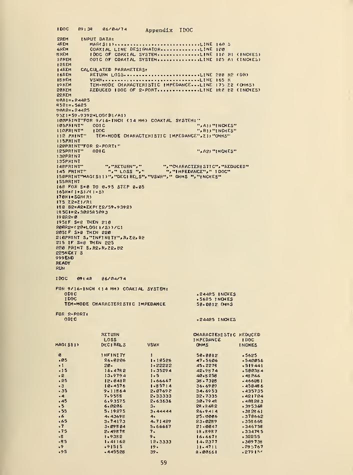
I DOC
2REM4REM6REM8 REMI0REM12REM14REMI6REM18 REM19REM20REM22REM80AI=. 2442585B1=.562590A2=. 244259 5ZI=59.9 392*L0GCB1/A| )
100PRINT"FOR 9/16-INCH (14 MM) COAXIAL SYSTEM:"I05PRINT" ODIC ",All"INCHES"110PRINT" IDOC ",B1» "INCHES"112 PRINT" TEM-MODE CHARACTERISTIC I MPEDANCE", 7 1
j "OHMS"1 15PRINT120PRINT"FOR 2-PORT:"
09:38 06/04/74 Appendix IDOC
INPUT DATA:MAGCSII) LINE 160 SCOAXIAL LINE DESIGNATOR LINE 100IDOC OF COAXIAL SYSTEM LINE 110 Bl CINCHES)ODIC OF COAXIAL SYSTEM LINE 105 Al CINCHES)
CALCULATED PARAMETERS:RETURN LOSS LINE 200 R2 CDB)VSWR LINE 165 RTEM-MODE CHARACTERISTIC I MPEDANCE. . .LINE 175 Z2 (OHMS)REDUCED IDOC OF 2-PORT LINE 180 B2 CINCHES)
125PRINT"130PRINT135PRINT140PRINT"145 PRINT"
ODIC ",A2| "INCHES"
", "RETURN", " ", "Of ARACTERI STI C", "REDUCED""," LOSS "»" "."IMPEDANCE"," IDOC"
150PRINT"MAGCS1 1) ", "DECI BELS", "VSWR", " OHMS "."INCHES"
155PRINT160 FOR S=0 TO 0.95 STEP 0.05165R=( l+S)/( 1-S)170R1=SQR(R)175 Z2=Z1/R1180 B2=A2*EXP(Z2/59.9392)185C1 = 2. 30258 509319 0R2=0195IF S=0 THEN 210200R2=(20*LOG< 1/S) )/Cl2051 F S>0 THEN 220210PRINT S, "INFINITY", R,Z2,B2215 IF S=0 THEN 225220 PRINT S,R2,R,Z2, B2225NEXT S999ENDREADYRUN
IDOC 09:40 06/04/74
FOR 9/ 16- INCH (14 MM) COAXIAL SYSTEM:ODICIDOCTEM-MODE CHARACTERISTIC IMPEDANCE
.24425 INCHES
.5625 INCHES50.0012 OHMS
FOR 2-PORT:ODIC .24425 INCHES
RETURN CHARACTERISTIC REDUCEDLOSS IMPEDANCE IDOC
MAGCS1 I) DECIBELS VSWR OHMS INCHES
INFINITY 1 50.0012 .5625.05 26.0206 1. 10526 47.5606 .540056. 1 20. 1.22222 45.2278 .519441.15 16.4782 1.35294 42.9874 .50038 4.2 13.9794 1.5 40.8258 .48266.25 12.0412 1.66667 38.7308 .46608
1
.3 10.4576 1.85714 36.6909 .45048 6
.35 9. 1 1864 2.0769 2 34.6953 .435735
.4 7.9 588 2.33333 32.7335 .421704
.45 6.93575 2.63636 30.79 48 .408 283
.5 6.0206 3. 28.8682 .39 53 68
.55 5. 19275 3.44444 26.9414 . 38 28 6
1
.6 4.43698 4. 25.0006 .370662
.65 3.74173 4.7 1429 23.0289 .358 668
.7 3.098 04 5.66667 21.0047 .346758
.75 2.49878 7. 18.8987 .33473 5
.8 1 . 9 38 2 9. 16.6671 .32255
.35 1.41 162 12.3333 14.2377 .309 738
.9 .91515 19. 1 1.471
1
.295767.95 .445528 39. 8.00661 .27915'
59
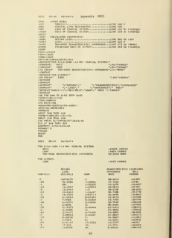
odic 09:44 P6/R4/74 Appendix ODIC
?REM INPUT DATA:4REM MAGCS11) LINE 160 S6REM COAXIAL LINE DESIGNATOR LINE 1008REM IDOC OF COAXIAL SYSTEM LINE 110 Bl CINCHES)1CREM ODIC OF COAXIAL SYSTEM LINE 105 Al CINCHES)12REM14REM CALCULATED PARAMETERS:I6REM RETURN LOSS LINE 200 R2 COB)1RREM VSWR LINE 165 RI9REM TEM-MODE CHARACTERISTIC IMPEDANCE. . .LI NE 17S £2 COHMS)2PREM INCREASED ODIC OF 2-PORT LINE 180 A2 CINCHES)22REM80A1=.2442S*5BI=.562590B2=.S6259 5?1=59.9 39 2*L0GC Bl/Al
)
100PRINT"FOR 9/16-INCH C14 MM) COAXIAL SYSTEMt"105PRINT" ODIC ", AU"INCHES"1I0PRINT" IDOC ",B1J "INCHES"112 PRINT" TEM-MODE CHARACTERISTIC IMPEDANCE", 7 ]
j "OHMS"1 15PRINT120PRINT"FOR 2-PORT:"I2S PRINT" IDOC ",B2j "INCHES"I30PRINT135PRINT140PRINT" ", "RETURN"," ", "CH ARACTERI STI C", "I NCREASED"145PRINT" "," LOSS"," ", "IMPEDANCE", " ODIC"150PRINT"MAGCS1 1)","DECI BELS", "VSWR", " OHMS "."INCHES"15SPRINT160 FOR S=0 TO 0.95 STEP 0.05165R=C 1*S)/C I-S)170R1=SQRCR)175 Z2=Z1/R118 0A2=B2/CEXPCZ2/59.9 39 2))185C1 = 2. 30258 5093190R2=0195IF S=0 THEN 210200R2=C20*LOGC 1/S) )/C1205IF S>0 THEN 220210 PRINT S, "INFINITY", R.Z2.A2215 IF S=0 THEN 225220PRINT S,R2»R,Z2,A2225NEXT S999ENDREADYRUN
ODIC 09: 47 06/04/7 4
FOR 9/16-INCH CI4 MM) COAXIAL SYSTEM:ODICIDOCTEM-MODE CHARACTERISTIC IMPEDANCE
.24425 INCHES
.5625 INCHES50.0012 OHMS
FOR 2-PORT:IDOC .5625 INCHES
RETURN CHARACTERISTIC INCREASELOSS IMPEDANCE ODIC
MAGCS1 1) DECIBELS VSWR OHMS INCHES
INFINITY 1 50.0012 .24425.05 26.0206 1.10526 47.5606 .2544.1 20. 1.22222 45.2278 .26449 7
.15 16.478 2 1.35294 42.9874 .27457
.2 13.9794 1.5 40.8258 .28 4653
.25 12.0412 1.66667 38.7308 .294778
.3 10.4576 1.85714 36.69 09 .30498 3
.35 9. 1 1864 2.07692 34.6953 .315308
.4 7.9 588 2.33333 32.7335 .325799
.45 6.93575 2.63636 30.7948 .336508
.5 6.0206 3. 28.8682 .347501
.55 5. 19275 3.44444 26.9414 .358853
.6 4.43698 4. 25.0006 .370662
.65 3.74173 4.71429 23.0289 .38 3058
.7 3.09804 5.66667 21 .0047 .396215
.75 2.498 78 7. 18.8987 .41038 4
.8 1.9382 9. 16.6671 .425951
.85 1.41 162 12.3333 14.2377 .44357
.9 .91515 19. 1 1 .471 1 .464524
.95 .445528 39. 8.00661 .492164
60
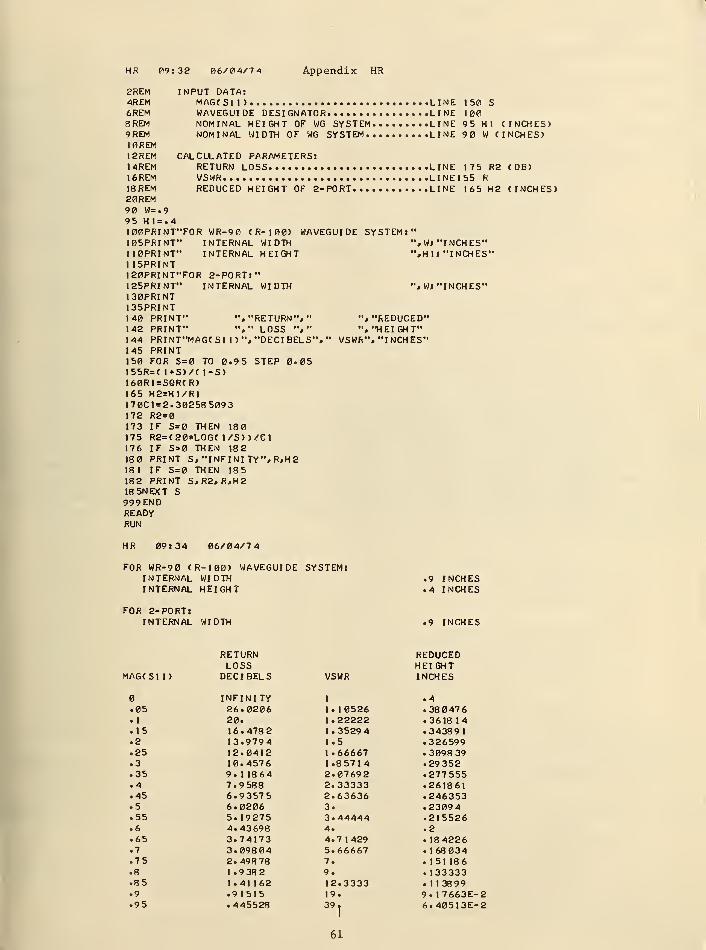
HR 09:32 06/04/74 Appendix HR
2REM INPUT DATA:4REM MAGCS11) LINE 150 S6REM WAVEGUIDE DESIGNATOR LINE 1008REM NOMINAL HEIGHT OF WG SYSTEM LINE 95 HI (INCHES)9REM NOMINAL WIDTH OF WG SYSTEM LINE 90 W CINCHES)10REM12REM CALCULATED PARAMETERS:14REM RETURN LOSS LINE 175 R2 (DB)16REM VSWR LINE155 R18REM REDUCED HEIGHT OF 2-PORT LINE 165 H2 (INCHES)20REM9 W=.995 Hl = .4100PRINT"FOR WR-90 (R-100) WAVEGUIDE SYSTEM:"105PRINT" INTERNAL WIDTH ", WJ "I NCH ES"110PRINT" INTERNAL HEIGHT ",H 1
I "INCHES"115PRINT120PRINT"FOR 2-PORT:"125PRINT" INTERNAL WIDTH ", W; "INCHES"130PRINT135PRINT140 PRINT" ", "RETURN", " ", "REDUCED"142 PRINT" "," LOSS "," "."HEIGHT"144 PRINT"MAG< SI 1 ) ", "DECIBELS"," VSWR", "INCHES"145 PRINT150 FOR S=0 TO 0.95 STEP 0.05155R=( 1*S)/C 1-S)160R1=SQR(R)165 H2=H1/R1170C1=2. 30258 5093172 R2=0173 IF S=0 THEN 180175 R2=(20*LOG( l/S))/ei176 IF S>0 THEN V8 2
180 PRINT S, "INFINITY", R,H2181 IF S=0 THEN 185182 PRINT S, R2, R,H2185NEXT S999ENDREADYRUN
HR 09:34 06/04/74
FOR WR-90 (R-100) WAVEGUIDE SYSTEM:INTERNAL WIDTH .9 INCHESINTERNAL HEIGHT .4 INCHES
FOR 2-PORT:INTERNAL WIDTH .9 INCHES
RETURN REDUCEDLOSS HEIGHT
MAGtSl 1) DECIBELS VSWR INCHES
INFINITY 1 .4.05 26.0206 1. 10526 .380476.1 20. 1.22222 .361814.15 16.478 2 1.3529 4 .343891.2 13.9794 1.5 .326599.25 12.0412 1.66667 .3098 39.3 10.4576 1.85714 .29352.35 9. 1 1864 2.07692 .277555.4 7.9 588 2.33333 .261861.45 6.93575 2.63636 .246353.5 6.0206 3. .23094.55 5.19275 3.44444 .215526.6 4.43698 4. .2.65 3.74173 4.7 1429 . 184226.7 3.098 04 5.66667 . 168034.75 2.49878 7. .151 186.8 1 . 9 38 2 9. . 133333.8 5 1.41 162 12.3333 . 1 13899.9 .91515 19. 9. 17663E-2.95 .445528 39, 6.40513E-2
61
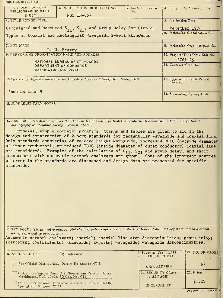
NBS-114A (REV. 7-73)
U.S. DEPT. OF COMM.BIBLIOGRAPHIC DATA
SHEET
1. PUBLICATION OR REPORT NO.
NBS TN-657
2. Gov't AccessionNo.
3. Recip 1 nt s Accessu o.
4. TITLE AND SUBTITLE
Calculated and Measured S , S__ , and Group Delay for Simple
Types of Coaxial and Rectangular Waveguide 2-fiort Standards
5. Publication Date
December 19746. Performing Organization Code
7. AUTHOR(S)R. W. Beatty
8. Performing Organ. Report No.
9. PERFORMING ORGANIZATION NAME AND ADDRESS
NATIONAL BUREAU OF ST/^DARDSDEPARTMENT OF COMMERCEWASHINGTON, D.C. 20234
10. Project/Task/Work Unit No.
276112511. Contract/Grant No.
12. Sponsoring Organization Name and Complete Address (Street, City, State, ZIP)
Same as Item 9
13. Type of Report & PeriodCovered
14. Sponsoring Agency Code
15. SUPPLEMENTARY NOTES
16. ABSTRACT (A 200-word or less factual summary of most significant information. If document includes a significant
bibliography or literature survey, mention it here.)
Formulas, simple computer programs, graphs and tables are given to aid in thedesign and construction of 2-port standards for rectangular waveguide and coaxial line.Only standards consisting of reduced height waveguide, increased ODIC (outside diameterof inner conductor) , or reduced IDOC (inside diameter of outer conductor) coaxial lineare considered. Examples of the calculation of S^, S21 and group delay, and theirmeasurement with automatic network analyzers are given. Some of the important sourcesof error in the standards are discussed and design data are presented for specificstandards.
17. KEY WORDS (six to twelve entries; alphabetical order; capitalize only the first letter of the first key word unless a proper
name; separated by semicolons)
Automatic network analyzers; coaxial; coaxial line step discontinuities; group delay;scattering coefficients; standards; 2-ports; waveguide; waveguide discontinuities.
18. AVAILABILITY py1
Unlimited
2 For Official Distribution. Do Not Release to NTIS
J Order From Sup. of Doc, U.S. Government Printing OfficeWashington, D.C. 20402, SD Cat. No. C13
_] Order From National Technical Information Service (NTIS)Springfield, Virginia 22151
19. SECURITY CLASS(THIS REPORT)
UNCLASSIFIED
20. SECURITY CLASS(THIS PAGE)
UNCLASSIFIED
21. NO. OF PAGE!
67
22. Price
$1.25
USCOMM.DC 29042-P74
NBS TECHNICAL PUBLICATIONS
PERIODICALS
JOURNAL OF RESEARCH reports National Bureauof Standards research and development in physics,
mathematics, and chemistry. Comprehensive scientific
papers give complete details of the work, including
laboratory data, experimental procedures, and theoreti-
cal and mathematical analyses. Illustrated with photo-
graphs, drawing's, and charts. Includes listings of otherNBS papers as issued.
Published in two sections, available separately:
• Physics and Chemistry (Section A)
Papers of interest primarily to scientists working in
these fields. This section covers a broad range of physi-
cal and chemical research, with major emphasis onstandards of physical measurement, fundamental con-
stants, and properties of matter. Issued six times a
year. Annual subscription: Domestic, $17.00; Foreign,
$21.25.
• Mathematical Sciences (Section B)
Studies and compilations designed mainly for the math-ematician and theoretical physicist. Topics in mathe-matical statistics, theory of experiment design, numeri-cal analysis, theoretical physics and chemistry, logical
design and programming of computers and computersystems. Short numerical tables. Issued quarterly. An-nual subscription: Domestic, $9.00; Foreign, $11.25.
DIMENSIONS/NBS (formerly Technical News Bul-
letin)—This monthly magazine is published to informscientists, engineers, businessmen, industry, teachers,
students, and consumers of the latest advances in
science and technology, with primary emphasis on the
work at NBS.DIMENSIONS/NBS highlights and reviews such
issues as energy research, fire protection, building
technology, metric conversion, pollution abatement,
health and safety, and consumer product performance.In addition, DIMENSIONS/NBS reports the results of
Bureau programs in measurement standards and tech-
niques, properties of matter and materials, engineeringstandards and services, instrumentation, and automaticdata processing.
Annual subscription: Domestic, £>9 • 45 Foreign$11.75 NONPERIODICALS
Monographs—Major contributions to the technical liter-
ature on various subjects related to the Bureau's scien-
tific and technical activities.
Handbooks—Recommended codes of engineering andindustrial practice (including safety codes) developed
in cooperation with interested industries, professional
organizations, and regulatory bodies.
Special Publications—Include proceedings of high-level
national and international conferences sponsored byNBS, precision measurement and calibration volumes,
NBS annual reports, and other special publications
appropriate to this grouping such as wall charts andbibliographies.
Applied Mathematics Series—Mathematical tables,
manuals, and studies of special interest to physicists,
engineers, chemists, biologists, mathematicians, com-puter programmers, and others engaged in scientific
and technical work.
National Standard Reference Data Series—Provides
quantitative data on the physical and chemical proper-
ties of materials, compiled from the world's literature
and critically evaluated. Developed under a world-wideprogram coordinated by NBS. Program under authority
of National Standard Data Act (Public Law 90-396).
Building Science Series—Disseminates technical infor-
mation developed at the Bureau on building materials,
components, systems, and whole structures. The series
presents research results, test methods, and perform-ance criteria related to the structural and environmen-tal functions and the durability and safety character-
istics of building elements and systems.
Technical Notes—Studies or reports which are completein themselves but restrictive in their treatment of asubject. Analogous to monographs but not so compre-hensive in scope or definitive in treatment of the sub-
ject area. Often serve as a vehicle for final reports of
work performed at NBS under the sponsorship of other
government agencies.
Voluntary Product Standards—Developed under pro-
cedures published by the Department of Commerce in
Part 10, Title 15, of the Code of Federal Regulations.
The purpose of the standards is to establish nationally
recognized requirements for products, and to provide
all concerned interests with a basis for common under-standing of the characteristics of the products. TheNational Bureau of Standards administers the Volun-tary Product Standards program as a supplement to
the activities of the private sector standardizingorganizations.
Federal Information Processing Standards Publications(FIPS PUBS)—Publications in this series collectively
constitute the Federal Information Processing Stand-ards Register. The purpose of the Register is to serve
as the official source of information in the Federal Gov-ernment regarding standards issued by NBS pursuantto the Federal Property and Administrative Services
Act of 1949 as amended, Public Law 89-306 (79 Stat.
1127), and as implemented by Executive Order 11717(38 FR 12315, dated May 11, 1973) and Part 6 of Title
15 CFR (Code of Federal Regulations). FIPS PUBSwill include approved Federal information processingstandards information of general interest, and a com-plete index of relevant standards publications.
Consumer Information Series—Practical information,
based on NBS research and experience, covering areasof interest to the consumer. Easily understandablelanguage and illustrations provide useful backgroundknowledge for shopping in today's technological
marketplace.
NBS Interagency Reports—A special series of interim
or final reports on work performed by NBS for outside
sponsors (both government and non-government). In
general, initial distribution is handled by the sponsor;public distribution is by the National Technical Infor-
mation Service (Springfield, Va. 22151) in paper copyor microfiche form.
Order NBS publications (except Bibliographic Sub-scription Services) from: Superintendent of Documents,Government Printing Office, Washington, D.C. 20402.
BIBLIOGRAPHIC SUBSCRIPTION SERVICES
The following current-awareness and literature-survey
bibliographies are issued periodically by the Bureau:
Cryogenic Data Center Current Awareness Service
(Publications and Reports of Interest in Cryogenics).
A literature survey issued weekly. Annual- subscrip-
tion: Domestic, $20.00; foreign, $25.00.
Liquefied Natural Gas. A literature survey issued quar-
terly. Annual subscription: $20.00.
Superconducting Devices and Materials. A literature
survey issued quarterly. Annual subscription: $20.00.
Send subscription orders and remittances for the pre-
ceding bibliographic services to the U.S. Departmentof Commerce, National Technical Information Serv-ice, Springfield, Va. 22151.
Electromagnetic Metrology Current Awareness Service
(Abstracts of Selected Articles on MeasurementTechniques and Standards of Electromagnetic Quan-tities from D-C to Millimeter-Wave Frequencies).
Issued monthly. Annual subscription: $100.00 (Spe-cial rates for multi-subscriptions). Send subscription
order and remittance to the Electromagnetic Metrol-
ogy Information Center, Electromagnetics Division,
National Bureau of Standards, Boulder, Colo. 80302.
U.S. DEPARTMENT OF COMMERCENational Bureau of StandardsWoshington. DC. 20234
OFFICIAL BUSINESS
Penalty for Private Use. $300
POSTAGE AND FEES PAIDU.S. DEPARTMENT OF COMMERCE
COM-215
"?6-&*
&GPO 1974— 677-235/1225 REGION NO
12 98


![Testing the Goddard Calc 11 Delay Model at the VLBA · Ignoring an anomaly at PT (see Fig. 2), ... Calc9 - Calc11 [BR] Fig. 1.— The difference between the delay model calculated](https://img.pdfslide.us/doc/110x75/609a68797a25ab366f708b5a/testing-the-goddard-calc-11-delay-model-at-the-vlba-ignoring-an-anomaly-at-pt-see.jpg)