Embed Size (px)
Citation preview

Cal Poly Satellite Positioning Systems: “Thrust or Bust!” Final Design Review
Presented by:
Gerardo Ramirez Jr. Milena Milich
Josh Neiman Joshua Tran
Advisor: Peter Schuster
Mechanical Engineering Department
California Polytechnic State University San Luis Obispo
May 2019
Prepared for:
Jay Miley
Mechanical Engineer, Astranis Space Technologies Corp.

Abstract
Satellites need a way to make precise corrections to their orbit and positioning. The purpose of this project is to design a gimbal mechanism for Astranis that orients an ion thruster along a requested vector. The gimbal must produce any vector within a 2.5° cone in a thirty-minute window. Current systems are expensive and not well suited to this application. The design must be operable in a space environment and optimize mass, size, and reliability.
Our design toggles between four discrete positions to achieve an average thrust vector. The gimbal accomplishes this using four solenoids that tilt a plate about a central hinge. The hinge allows for low friction rotation in only two axes. It also contains an integrated restoring force, which will passively restore the thruster to center in event of actuator failure. A linkage assembly connects the solenoids to the thruster plate, allowing for mechanical advantage and a low profile. Four hard stops in the linkage assembly physically define the actuation angles.
We initially pursued several designs in parallel before narrowing down to a single design for our confirmation prototype. After manufacturing this prototype, we tested our design to verify range and accuracy of the vector and the ability of the gimbal to move an ion thruster on Earth. The gimbal produced a 2.445° cone with a vector precision of ±0.01° and successfully actuated a 5kg load with a similar center of mass. The gimbal has an envelope of 199x199x44mm and a total mass of 0.926kg. Future testing should include environment tests and complete system tests to ensure full functionality in the intended application.
Although our final prototype is not intended to be launch ready, the work accomplished for this project will benefit Astranis as they pursue a flight ready design.

Statement of Disclaimer
Since this project is a result of a class assignment, it has been graded and accepted as fulfillment
of the course requirements. Acceptance does not imply technical accuracy or reliability. Any use
of information in this report is done at the risk of the user. These risks may include catastrophic
failure of the device or infringement of patent or copyright laws. California Polytechnic State
University at San Luis Obispo and its staff cannot be held liable for any use or misuse of the
project.

Table of Contents
1.0 INTRODUCTION ................................................................................................................................................. 1
2.0 BACKGROUND .................................................................................................................................................... 1 2.1 CUSTOMER RESEARCH ......................................................................................................................................... 1 2.2 PRODUCT RESEARCH ............................................................................................................................................ 2
2.2.1 Dual Axis Gimbals ....................................................................................................................................... 2 2.2.2 Three Arm Gimbal ....................................................................................................................................... 3 2.2.3 Ball Joint and Rotary Actuators ................................................................................................................... 3 2.2.4 Full Sphere of Motion Gimbals .................................................................................................................... 4 2.2.5 Patent Search Results .................................................................................................................................. 5
2.3 TECHNICAL RESEARCH ........................................................................................................................................ 6 2.4 ACTUATOR RESEARCH ......................................................................................................................................... 6
3.0 OBJECTIVES ........................................................................................................................................................ 8 3.1 QUALITY FUNCTION DEPLOYMENT ...................................................................................................................... 9 3.2 ENGINEERING SPECIFICATIONS ............................................................................................................................ 9
4.0 CONCEPT DESIGN ........................................................................................................................................... 11 4.1 PRELIMINARY IDEATION .................................................................................................................................... 11 4.2 DESIGN PATH ..................................................................................................................................................... 12 4.3 DESIGN REFINEMENT ......................................................................................................................................... 13
4.3.1 Primary Design: Dual Pivot Mechanism ................................................................................................... 15 4.3.2 Alternate Design 1: Four Linear Actuator Gimbal .................................................................................... 16 4.3.3 Alternate Design 2: Z-Locked Double Swivel ............................................................................................ 17
4.4 POST-PDR DESIGN ITERATIONS AND DEVELOPMENT ........................................................................................ 18 4.4.1 Dual Pivot Design Development ................................................................................................................ 18 4.4.2 Linear Actuation Design Development ...................................................................................................... 19
4.5 PRELIMINARY ANALYSIS .................................................................................................................................... 21
5.0 FINAL DESIGN .................................................................................................................................................. 22 5.1 DESIGN OVERVIEW ............................................................................................................................................ 22
5.1.1 Two-Axis Hinge .......................................................................................................................................... 23 5.1.2 Linkage and Solenoid Subassembly ........................................................................................................... 25 5.1.3 Plates ......................................................................................................................................................... 26
5.2 ELECTRICAL AND SOFTWARE DESIGN ................................................................................................................ 27 5.3 DESIGN ANALYSIS.............................................................................................................................................. 28 5.4 POST CDR DESIGN CHANGES ............................................................................................................................ 30 5.5 SAFETY, MAINTENANCE, AND REPAIRS .............................................................................................................. 34 5.6 COST ANALYSIS ................................................................................................................................................. 35
6.0 MANUFACTURING PLAN ............................................................................................................................... 36 6.1 PROCUREMENT ................................................................................................................................................... 36 6.2 MANUFACTURING .............................................................................................................................................. 36 6.3 ASSEMBLY ......................................................................................................................................................... 39
7.0 DESIGN VERIFICATION ................................................................................................................................. 41 7.1 TEST #1: VECTOR PRECISION BY LASER POINTER .............................................................................................. 42 7.2 TEST #2: VECTOR PRECISION BY INERTIAL MEASUREMENT UNIT ...................................................................... 43 7.3 TEST #3: VECTOR ACCURACY BY MECHANICAL MEASUREMENT ...................................................................... 44 7.4 TEST #4: 1G OPERATION TEST ........................................................................................................................... 45 7.5 TEST #5: TORQUE TEST ...................................................................................................................................... 45 7.6 INSPECTION AND ANALYSIS RESULTS ................................................................................................................ 46

7.7 FUTURE TESTING................................................................................................................................................ 46
8.0 PROJECT MANAGEMENT.............................................................................................................................. 47
9.0 CONCLUSIONS AND RECOMMENDATIONS ............................................................................................. 47 9.1 RESULTS............................................................................................................................................................. 47 9.2 NEXT STEPS ....................................................................................................................................................... 48 9.3 FINAL THOUGHTS ............................................................................................................................................... 50
REFERENCES .......................................................................................................................................................... 51 Appendices: [A] Quality Function Deployment Chart [B] Pugh Matrix [C] Design Refinement Decision Matrix [D] Alternative Designs [E] Drawing Package [F] Product Literature [G] Design Analysis [H] Design Hazard Checklist [I] Failure Modes and Effects Analysis [J] Risk Assessment [K] Project Budget [L] Design Verification Plan and Report [M] Operator’s Manual [N] Gantt Chart

Table of Figures FIGURE 1: MOOG ION THRUSTER GIMBAL [1] 2 FIGURE 2: TETHERS UNLIMITED COBRA GIMBAL [2] 3 FIGURE 3: RUAG ELECTRIC PROPULSION MECHANISM (EPMEC) [3] 3 FIGURE 4: NEA ELECTRONICS G35 GIMBAL [4] 4 FIGURE 5: AEROTECH AMG100-LP LOW-PROFILE DIRECT-DRIVE GIMBAL [5] 4 FIGURE 6: BOUNDARY DRAWING 8 FIGURE 7: OVERVIEW OF THE INITIAL DOWN-SELECTION AND IDEA REFINEMENT PROCESS. 13 FIGURE 8: DUAL PIVOT CONCEPT 15 FIGURE 9: FOUR LINEAR ACTUATOR INITIAL CONCEPT 16 FIGURE 10: Z-LOCKED DOUBLE SWIVEL DESIGN 17 FIGURE 11: DUAL PIVOT EARLY DESIGN AND INITIAL PROTOTYPE 18 FIGURE 12: ISOMETRIC AND CROSS-SECTIONAL VIEWS OF DUAL PIVOT FINAL DESIGN 19 FIGURE 13: PROTOTYPE OF VERTICAL SOLENOID DESIGN. 20 FIGURE 14: ANGLED SOLENOID DESIGNS AND PROTOTYPES 21 FIGURE 15: 3D PLOTS OF VECTOR AVERAGING CONCEPTS 22 FIGURE 16: FINAL DESIGN 23 FIGURE 17: MAIN COMPONENTS OF FINAL DESIGN LABELED. 23 FIGURE 18: TWO-AXIS HINGE ASSEMBLY 24 FIGURE 19: SPRING-PLUNGER PROVIDE THE RESTORING FORCE AFTER ACTUATION 24 FIGURE 20: LINKAGE AND SOLENOID SUBASSEMBLY. 25 FIGURE 21: CROSS-SECTIONAL VIEW OF SOLENOID AND LINKAGE SYSTEM. 25 FIGURE 22: SWIVEL OF BALL JOINT ROD END IN ACTUATED POSITION. 26 FIGURE 23: BASE PLATE (LEFT) AND THRUSTER PLATE (RIGHT). 27 FIGURE 24: ELECTRICAL SCHEMATIC 27 FIGURE 25: 2D AND 3D REPRESENTATION OF OUR CORNER VECTORS 28 FIGURE 26: DIAGRAM OF FORCES EXPERIENCED DURING ACTUATION. 29 FIGURE 27: FORCE CURVES FOR THE SELECTED SOLENOID (A), ACTUATION TORQUE FOR THE DESIGN (B), AND
PROPOSED ACTUATION CYCLE (C) 30 FIGURE 28. POST-CDR FINAL GIMBAL DESIGN 30 FIGURE 29. PRE-CDR ASSEMBLY STORY (LEFT) AND POST-CDR ASSEMBLY STORY (RIGHT). 31 FIGURE 30. PRE-CDR THRUSTER PLATE (LEFT) AND POST-CDR THRUSTER PLATE (RIGHT). 31 FIGURE 31. PRE-CDR HINGE BASE (LEFT) AND POST-CDR HINGE BASE (RIGHT). 32 FIGURE 32. PRE-CDR SOLENOID BRACKET (LEFT) AND POST-CDR SOLENOID BRACKET (RIGHT). 32 FIGURE 33. FINAL GIMBAL DESIGN WITH MOCK THRUSTER AND ELECTRONICS BOX 33 FIGURE 34. ACRYLIC MOCK THRUSTER WITH TEST MASSES FOR A SIMILAR CENTER OF GRAVITY 33 FIGURE 35. MOCK THRUSTER BASE PLATE (LEFT) AND LASER POINTER BRACKET (RIGHT). 34 FIGURE 36. ASSEMBLY OF VECTOR PRECISION TEST WITH THE ACTIVE LASER POINTER. 34 FIGURE 37. COMPLETE 3D-PRINTED PROTOTYPE 36 FIGURE 38. COMPLETED THRUSTER PLATE (LEFT) AND BASE PLATE (RIGHT). 37 FIGURE 39. TAPPING SOLENOID THREADS INTO SOLENOID BRACKET 38 FIGURE 40: COMPLETED HINGE (LEFT) AND LINKAGE (RIGHT). 38 FIGURE 41: LASER CUT SIDES (LEFT), ELECTRONICS BOX (CENTER), MOCK THRUSTER (RIGHT) 38 FIGURE 42. TWO-AXIS HINGE ASSEMBLY 39 FIGURE 43. LINKAGE AND SOLENOID ASSEMBLY 40 FIGURE 44. FINAL ASSEMBLY 40 FIGURE 45. COMPLETED GIMBAL 41 FIGURE 46. ASSEMBLED GIMBAL WITH THE MOCK THRUSTER 41 FIGURE 47. LASER POINTER VECTOR PRECISION TESTING SETUP 43 FIGURE 48. IMU TEST VARIANCE 44 FIGURE 49. IMU ANGLE DATA FOR A SERIES OF EIGHT ACTUATIONS 44

FIGURE 50. MOCK THRUSTER WITH INTERNAL SPACE FOR ADDING WEIGHTS AND A SLOT ON THE SIDE FOR MOUNTING AN IMU TO THE THRUSTER PLATE 45
FIGURE 51. TORQUE TEST EXPERIMENTAL SETUP FOR THE IN-AXIS AND OFF AXIS CONFIGURATIONS 46
Table of Tables
TABLE 1: RELEVANT PATENTS ...................................................................................................................................... 5 TABLE 2: LINEAR ACTUATOR SELECTION SUMMARY ..................................................................................................... 7 TABLE 3: THRUSTER GIMBAL DESIGN SPECIFICATION TARGETS ................................................................................... 9 TABLE 4: INITIAL CONCEPTS ....................................................................................................................................... 12 TABLE 5: SUMMARY OF MAJOR DESIGN CONCEPTS .................................................................................................... 14 TABLE 6: OFF THE SHELF COMPONENTS ...................................................................................................................... 35 TABLE 7: PROTOLABS CNC MACHINED COMPONENTS ............................................................................................... 35 TABLE 8: PROTOLABS CNC MACHINING QUOTES ....................................................................................................... 37 TABLE 9: COMPLETED SPECIFICATION TABLE ............................................................................................................. 42 TABLE 10: VECTOR PRECISION IMU TEST RESULTS ................................................................................................... 44 TABLE 11: CALCULATED VECTOR CONE ANGLE WITH RESPECT TO VERTICAL POSITION ........................................... 45

1
1.0 Introduction The goal of the project is to design and prototype a device to position a low-force thruster on a satellite for our sponsor, Astranis Space Technologies Corp. Astranis is a start-up that designs telecommunications satellites to provide internet access to rural areas. Our point of contact with the company for this project is Jay Miley, a structural engineer at Astranis. The team working to solve this problem is composed of four mechanical engineering students at California Polytechnic State University, San Luis Obispo for a senior design project. This project lasted for three quarters culminating in a final prototype and a design expo. This document first discusses the results of the team’s research, then addresses the scope of the project and clearly defines requirements that a successful design must meet. The document proceeds to give an overview of our ideation process and initial concepts presented in the preliminary design review. It then describes our idea refinement process and development of structural prototypes to influence the final design direction. After presenting the details of our final design, the report covers our manufacturing procedures, and design verification procedures and results. Finally, it discusses conclusions drawn from the project and recommendations for future iterations. 2.0 Background To fully understand the project presented to us, our team studied the technical background and current relevant literature. This initial analysis helped us to clearly define the problem and develop an effective solution process. Through meetings, observations, and research, we generated a list of requirements to fit the needs of our sponsor, Astranis. We then performed a patent search and discovered ways we could improve on existing products while noting the reasons that those products were successful. We also conducted technical research to better understand the potential challenges posed by working in a space environment and the relevant standards that the mechanism should be able to fulfill. 2.1 Customer Research Astranis is a start-up company working to develop technology that provides lower cost telecommunications to the world. They specifically focus on bringing online rural areas with little access to the internet. In pursuit of this goal, they are creating smaller and lower cost telecom satellites. If successful, our system may be integrated onto a future satellite iteration. The gimbal will enable small adjustments, making the overall satellite positioning system more efficient. Our sponsor provided us the following baseline requirements for our design: • Minimize mass • Minimize complexity • Ensure reliability

2
• All materials vacuum compatible • Survive a temperature range of -100 °C to 200 °C • Minimize volume within a boundary of 200x200x80mm, particularly the 80mm height • Accommodate mounting system and selected thruster We also received guidance on how to approach each requirement. The priority for Astranis is simple and reliable positioning. The design of the satellite is not yet defined, so specific volume, mass, cost, and pointing range are not hard requirements. However, our system must be able to survive the space environment. Although our design is not required to survive launch considerations, we should consider how it will accommodate a support mechanism during launch. Design and accommodation of this constraint system is out of the scope of this project. 2.1.1 Ongoing Changes to Design Requirements Over the course of the project, the baseline requirements were modified to reflect the challenges discovered by the project. The initial 5° cone was reduced to a 2.5° cone due to the challenges posed by actuating the gimbal with the chosen mechanism. Additionally, there were concerns about external forces on the gimbal, particularly the hose that will attach to the gimbal. Finally, in the case of a failure Astranis wanted the gimbal to either be at or passively return to a known position. These changes are summarized as: • 2.5° cone as the range of actuation • 0.2Nm holding torque • Have a known no power reset position in the case of failure 2.2 Product Research As part of the background research, we found existing products and examined their potential for solving our sponsor’s needs and wants. The following are four categories of products we discovered through an extensive online search that could potentially be useful for our design. 2.2.1 Dual Axis Gimbals
Figure 1: MOOG Ion Thruster Gimbal [1]

3
Moog developed a gimbal mechanism (Figure 1) to provide vector maneuvering for thrust of the Hayabusa satellite which used four gimbaled ion thrusters. Hayabusa was a robotic spacecraft launched in 2003 by the Japanese Aerospace Exploration Agency (JAXA) to return sample material from a near-Earth asteroid [1]. This gimbal was specifically designed for Hayabusa’s ion thruster, which is a method of electric propulsion. The device is a dual axis gimbal actuated by linear actuators. It uses stepper motors with lead-screw actuation for positioning. The gimbal has a vector range of ±5° in both X and Y axes, an operating temperature range of -20° to 80°C and has envelope dimensions of 16x16x7 inches. 2.2.2 Three Arm Gimbal
Figure 2: Tethers Unlimited COBRA Gimbal [2] The second type of gimbal we found is the three-armed gimbal. Tethers Unlimited makes the COBRA gimbal (Figure 2), a three degree of freedom mechanism designed for precision pointing of thrusters or sensors. The device uses three stepper motors to define its degrees of freedom [2]. The COBRA line provides three models, COBRA-C, COBRA-HPX, and COBRA-UHPX, with an open-loop stepper, closed-loop stepper and brushless closed-loop stepper respectively. These models have a hemispherical range of 2πsr. The envelope dimensions for the gimbals ranges from 100 to 165 mm in diameter and 26 to 40 mm in stack height. 2.2.3 Ball Joint and Rotary Actuators
Figure 3: RUAG Electric Propulsion Mechanism (EPMEC) [3]

4
RUAG created an electric propulsion pointing mechanism (Figure 3) for the SMART-1 spacecraft developed by the Swedish Space Corporation. The spacecraft used an electric propulsion system as the main thruster power source for the mission, with EPMEC used as the steering mechanism. The EPMEC design uses two rotary actuators, which drive the thruster via a strut-linkage around a spherical joint [3]. The EPMEC enables pointing within a half-cone angle of 10°. The mechanism has an operating temperature range of -45° to 65° C. 2.2.4 Full Sphere of Motion Gimbals
Figure 4: NEA Electronics G35 Gimbal [4] NEA Electronics has developed actuators specifically for precision spacecraft pointing applications. NEA’s G35 gimbal (Figure 4) is comprised of two P35 actuators combined with brackets to create a multi-axis gimbal [4]. The P35 actuators provide two step angle options, 0.0075° output step angle and a 0.0024° output step angle for very fine positioning. A single P35 actuator is 4.75 inches in diameter and 3.90 inches in height. Each P35 actuator can provide voltage telemetry over the entire 360 degrees of travel. The mechanism has an operating temperature range of -50° to 105°C.
Figure 5: Aerotech AMG100-LP Low-Profile Direct-Drive Gimbal [5] High precision gimbals have been designed for precision applications. Aerotech develops gimbals to provide ultra-precise angular positioning. The AMG100-LP gimbal (Figure 5) is designed for

5
directing optics, lasers, antennas, and sensors to very precise pointing angles [5]. The AMG-LP utilizes Aerotech’s high torque S-series brushless, slotless servomotors. The gimbal provides 360 degrees of rotation about the azimuth and elevation angles. The gimbal provides an accuracy up to ±24 µrad when calibrated or ±192 µrad when uncalibrated. The envelope dimensions for the gimbal are 292 mm in diametral clearance and 243 mm in height. 2.2.5 Patent Search Results A patent search was conducted to examine current technologies related to gimballed thrust control. The primary purpose of this investigation was for industry research and idea generation. The secondary purpose is to be aware of what patents may be incorporated or referenced in our final design. We identified five relevant patents in Table 1 along with a short description of their contents.
Table 1: Relevant Patents Patent Title Patent Number Description
Ion Thruster Support and Positioning System [6]
US 5,738,308 A Linkage that allows ion thruster positioning using three rotary actuators
Spacecraft Attitude Control And Momentum Unloading Using Gimballed And Throttled Thrusters [7]
US 5,349,532 A Single axis gimbals positioned on the corners of the satellite allow for attitude control
Gimbaled Thruster Control System [8]
US 6,481,672 B1 Calculation of gimbal angle required for torque adjustments
Mechanism For Thrust Vector Control Using Multiple Nozzles [9]
US 5,662,290 A Mechanism to control angle of nozzle
Attitude Slew Methodology For Space Vehicles Using Gimbaled Low-Thrust Propulsion Subsystem [10]
US 9,522,746 B1 System of four gimballed thrusters for attitude control in the event of reaction wheel failure
The Ion Thruster Support and Positioning System patent was helpful to us because it addresses the differences in requirements for a gimbal mechanism for liquid fuel thruster and ion thruster systems. It also discusses how these differences guided the design of the system being patented. The patents Spacecraft Attitude Control and Momentum Unloading and Mechanism for Thrust Vector Control Using Multiple Nozzles are not as helpful for our project because they rely on the thrusters having certain characteristics that we cannot assume. The Attitude Slew Methodology patent also relies on aspects of the satellite beyond our control for this project, namely that it

6
requires the satellite to have four thrusters dedicated to attitude control. These patents were useful in helping us further understand the scope of our project, but none met all the specifications of our application. 2.3 Technical Research In orbit, satellite systems are exposed to low pressures, high doses of radiation, thermal cycling, atomic oxygen, and impacts from micrometeoroids and other debris. The mechanism will need to maintain its accuracy under these conditions. The vacuum environment limits material selection, as outgassing will occur in certain materials. This removes cadmium, zinc, magnesium, and many plastics from the list of viable material options. Some that work well under these conditions are aluminum, nickel, titanium, and steel. [11] Atomic oxygen can cause corrosion in some materials such as aluminum which requires a coating. Astranis provided a survival temperature cycle for this project of +200℃/-100℃, although we will select a more moderate temperature requirement for mechanism operation. Designing for high radiation dosage beyond material selection is outside the scope of what is feasible to test for this project and Cal Poly does not have the facilities or equipment to test these requirements.
Objects sent into space are subject to multiple standards to ensure safety, reliability, and quality. The Air Force Space Command published the Space and Missile Systems Command Standard, known as SMC-S-016, which contains the testing requirements for our system. The device must pass both the electrical and structural standards [12]. Additionally, the General Environmental Verification Standard published by the NASA Goddard Space Flight Center contains requirements for the testing of mechanical elements, including strength qualifications, mechanical shock tests, and vibration tests [13]. Finally, for material selection, the American Society of Testing and Materials prescribes the Standard Test Method for Total Mass Loss and Collected Volatile Condensable Materials from Outgassing in a Vacuum Environment. The object or system is exposed to a near vacuum (7x10⁻³ Pa) for 24 hours at 125℃. For use on spacecraft, a Total Mass Loss of <1% and a Collected Volatile Condensable Material of <0.1% has been used to validate previous spacecraft components [14].
As with the environmental requirements, not all specifications set by these standards can be tested using equipment available at California Polytechnic State University. Certain tests, such as extended life tests, will not be possible given these restrictions.
2.4 Actuator Research Actuator selection proved to be a critical factor in selecting a final design, so it is worth discussing the merits of each type. Astranis desired that the design should passively return to center so that in case of a failure, the ion thruster would remain useable at a known direction. Table 2 summarizes the benefits and problems for several types of linear actuators. The viability ranking was chosen for our design and requirement set. Should the requirements or the design change, the viability

7
would change as well. For example, if the requirement of a passive return to center was not included, piezoelectric actuators would have a higher viability.
Table 2: Linear actuator selection summary
Actuator Type Benefits Problems Viability Pull Solenoid Simple construction
Free when not powered Single direction of force Lower max force Low actuation distance
Viable
Push Solenoid Simple construction Free when not powered
Single direction of force Lower max force Plunger pin is prone to wear Difficulty of force transfer Low Actuation Distance
Not Viable
Nitinol Memory
Lighter construction Retracted when not powered
Lower force Fragile High temperature sensitivity Exposed electronics Low actuation distance
Not Viable
Pin Pullers Extremely high force Retracted when not powered
Extremely low life Single direction of force Low actuation distance
Not Viable
Rack and Pinion
High, dual direction force High potential load Low power usage High actuation distance
Large envelope Requires a gearbox Additional motor requirements Heavy construction
Not Viable
Screw Mechanism
High force High potential load Low power usage High actuation distance
Actuator extends beyond the motion envelope Potential screw failure Additional motor requirements Heavy construction
Not Viable
Piezoelectric Extremely precise actuation Adequate force High actuation distance
Extremely high price Potential temperature sensitivity No passive return Locked when not powered
Not Viable
Voice Coils Dual direction force Centered when not powered
Lower max force Requires lower force Low actuation distance
Viable
Of the linear actuators, pull solenoids, piezoelectrics, and voice coils are the most promising linear actuators. Solenoid are the most favored due to their extremely simple construction, low cost and adequate throw. They also have the highest forced when fully retracted. Piezoelectric actuators are promising for both force and life cycles, but are self-locking. This is useful for other designs, but

8
since a passive return to center was desired piezoelectric actuators will not work for this application. Voice coils are also good choices, as they are similar construction to solenoids. Voice coils and piezoelectric actuators can provide the necessary force with the ability to actuate in both directions, reducing the required number of actuators to two. Both piezoelectric actuators and voice coils are worth pursuing for future designs but are significantly more expensive than solenoids. For rotary actuator selection, we searched primarily for brushless DC motors. Brushed motors brought life concerns and stepper motors require full power to hold at a single position. Additionally, any force will move the location of a stepper motor. Gearboxes were eliminated after conversations with Astranis due to their multiple potential failure modes. It was possible to select a motor with enough torque without a gearbox, but motors without a gear reduction do not perform well at stall, having high power draw and low life. One other notable actuator is rotary solenoids. These actuators have binary or ternary positions that they are designed to maintain a position, rather than rotate through a set of positions like a motor. However, rotary solenoids are low force but some do produce enough torque for this application.
3.0 Objectives For this project, we will design and prototype a precise positioning system for an ion thruster to allow the satellite to stay in orbit longer. Astranis has provided us with requirements that we will attempt to meet by completing following objectives.
Figure 6: Boundary Drawing
The boundary drawing in Figure 6 shows our system integrated into a satellite. The dashed lines represent the gimbal boundary. We will accommodate the mounting interface of the satellite and the thruster on both ends of our boundary. This will be in the form of a bolt pattern and thruster specifications. We will also accommodate any cables from the thruster to the satellite. The gimbal itself will also have electrical connections to the satellite. In a full satellite, the gimbal power and control system would be integrated into the satellite hardware. For our prototype, we will have a ‘breakout board’ to simulate these systems and actuate the gimbal. The device must fit within a 200x200x80 mm envelope. It must also be as lightweight as possible to reduce the amount of fuel needed, thus reducing launch cost. There will be no way to repair the system once launched so it must be reliable for the lifetime of the satellite. The device must be

9
able to angle the thruster within a ±2.5° cone of the neutral position. The gimbal does not need to produce an instantaneous vector but must produce an accurate net vector within a 30- minute time window. We can move the thruster to multiple positions for different durations during the window to obtain this average thrust. A larger angular range is allowable if we can obtain the same positioning requirements. Since the device will be operated in space, it needs to function in a vacuum. It also needs to withstand extreme temperatures, so a survival temperature range of -100 °C to 200 °C must be met. In one of the later design stages, we will specify the optimal temperature operating range for the gimbal. Our sponsor has stated that we are not responsible for considering launch loads and vibrations. In order to reduce cost and complexity, it is desirable for the device to be easily manufacturable. It is also desirable for the device to be energy efficient, actuate quickly, and position precisely. 3.1 Quality Function Deployment In order to ensure we are meeting the correct customer needs we have created a House of Quality chart, shown in Appendix A. We identified system reliability and accuracy as the highest priority requirements for our customer. This chart also identifies how we can test whether each design meets customer requirements. Based on our initial research our highest priority specifications are vector precision, temperature resistance, actuation time, and the lifetime hours of operation. Vector precision is a test of how accurately and repeatedly we can output a given vector. 3.2 Engineering Specifications A successful design will follow the specifications listed in Table 3. The highest risk specifications, denoted by (H) in the Risk column are the survival temperature, cycle life, accuracy, and off-axis holding torque; these are the specifications that will be most difficult for us to meet. The Compliance column shows whether we will determine if the specification is met by either inspection (I), analysis (A), or testing (T). Specifications 9 through 12 were added over the course of the design process as we became more familiar with the project and its goals.
Table 3: Thruster Gimbal Design Specification Targets
Spec. #
Parameter Requirement or Target
Tolerance Risk Compliance
1 Mass 1.5kg Max M I, A
2 Product Size 200x200x80mm Max M I
3 Vector Precision ±0.5° Max H T, A
4 Cost $3500 Max M I
5 Operational Temperature
-40°C to 100°C Min M A

10
Spec. #
Parameter Requirement or Target
Tolerance Risk Compliance
6 Survival Temperature
-100°C to 200°C Min H A
7 Operational in Vacuum
10−8 Pa Min M A
8 Cycle life 10 Years Min H A
9 Vector Cone 2.5° Min M T
10 On- Axis Holding Torque
0.2Nm Min M T
11 Off-Axis Holding Torque
0.2Nm Min H T
12 Actuation in 1G Go/No-go N/A M I
Specification Descriptions:
1. Mass System mass will include the mass of the gimbal mechanism, the gimbal-thruster interface, and the gimbal-satellite interface. Mass will be tested weighing these components on a scale
2. Product Size Product size will be measured by determining what the size would be of the smallest three-dimensional envelope the system could fit within.
3. Vector Accuracy We will measure vector accuracy by placing a laser at the center of the mechanism and comparing the resultant angle with the expected.
4. Cost The total cost of the system is the sum of the cost of each of the components in the system; when products are purchased in bulk and only some are used, we will calculate the cost of the individual parts for use in the total.
5. Operational Temperature The operational temperature range is the range of temperatures at which the system is fully functional during operation.
6. Survival Temperature The survival temperature range is the range of temperatures at which the system does not suffer any permanent damage.
7. Operational in Vacuum This specification determines whether the system will operate at extremely low pressures.
11
8. Cycle Life We will not test for the life of our design; it is beyond the scope of the project.
9. Vector Cone Vector cone is the physical measurement of the maximum cone angle we can achieve. This angle occurs between two corner vectors, so it is defined as the smallest corner angle times √2.
10. On- Axis Holding Torque Holding torque is defined as the torque required to break the thruster away from its hard stop while it is actuated. For on-axis, a force is applied directly opposite to the actuated side.
11. On- Axis Holding Torque Holding torque is defined as the torque required to break the thruster away from its hard stop while it is actuated. For on-axis, a force is applied in the corner adjacent to the actuated side.
12. Actuation in 1G The gimbal must move a 5 kg mass in the vertical position into and out of each corner location under standard Earth gravity.
4.0 Concept Design
Before pursuing a single design option, our team spent time brainstorming and investigating potential solutions to determine their feasibility and identify their benefits, as well as areas of concern. Our concept development resulted in multiple solutions. We selected three top concepts for further development, which we reduced to two and then eventually a single concept. In this chapter, we detail our ideation methods, initial concepts, and design direction.
4.1 Preliminary Ideation Our design selection process began with initial brainstorming sessions. In these sessions, we allowed all ideas to be on the table regardless of how outlandish or infeasible the ideas seemed. After amassing a large stack of initial idea sketches and concepts, we down-selected for those ideas which were impossible or beyond our abilities. We then selected the best ideas from the list using a Pugh Matrix included in Appendix B. A Pugh matrix uses a design idea as the datum and evaluated ideas based on their relative performance on a given criteria compared to a datum idea. The datum we used in this case was a two degree of freedom rotating arm. These tools allowed us to decide which ideas best fit the requirements for the project and eliminate ideas that performed poorly relative to the others. We repeated this process of ideating and down-selecting several times and we noticed several classes of ideas beginning to emerge. At this point, we decided to each individually research and ideate on a different idea class to determine any initial problems or challenges. This resulted in some preliminary concepts (Table 4) that we presented to Jay Miley on November 8th.

12
Table 4: Initial Concepts
Concept Description Advantages Disadvantages Single DOF
Thruster is mounted on a plate at fixed angle. The plate can then be rotated by a motor between two calculated positions to achieve the desired vector.
- simplicity - potential for high reliability - single actuator - few failure modes
- difficult cable routing - requires many actuations
Three Linear Actuators
The thruster can be directed to any angle in the 5° cone extending the linear actuators to different lengths.
- instantaneous pointing - no gear reduction required - simple cable routing
- requires three precise actuators - no redundancy - actuators are structural components
Rotating Table
Two mechanisms make up this design, a rotating table and a hinged platform. The rotating table is free to spin 360°.
- instantaneous pointing - ability to point to normal if bottom motor fails
- requires two actuators - difficult cable routing - complicated linkage system
Double Swivel
Two concentric rings are each sloped 2.5° on one face. A motor mounted to the base drives the bottom ring and a motor mounted to the bottom ring drives the upper ring.
- instantaneous pointing - ability to point to normal if bottom motor fails
- requires two actuators - difficult cable routing - requires many sliding surfaces
4.2 Design Path After presenting these ideas to our sponsor, Jay informed us that rotating the thruster was not a viable solution due to the complexities of cable routing. With this knowledge, we eliminated or refined our preliminary concepts. The flowchart in Figure 7 details the evolution of our preliminary designs into three major design concepts.

13
Figure 7: Overview of the initial down-selection and idea refinement process.
The conceptual design is very important to the success of our project and likely will represent the most value added to Astranis as they pursue a launch-ready version of the gimbal. Therefore, we decided to continue investigating multiple concepts in parallel. We selected three top concepts for further development and used a decision matrix to evaluate these concepts with complexity, reliability, and vector repeatability as the highest weighted factors. This chart is attached in Appendix C. Of these designs, our primary design path is a concept called the Dual Pivot. This gimbal has two rotational degrees of freedom along with hard-stops to define four angular positions. We are also considering two other options: an evolution of the Double Swivel concept, and a Linear Actuator concept. Appendix D lists alternative designs that we are not pursuing but came out of a result of idea refinement. 4.3 Design Refinement
The next step in our concept design process was to explore the selected designs to greater depth. Table 5 introduces the more refined versions of the concepts generated through our preliminary ideation that we decided to move forward with. In this section, we will describe how each of these designs would operate, some advantages of each, as well as their limitations.

14
Table 5: Summary of Major Design Concepts
Concept Description Dual Pivot
This concept uses two pivoting plates and hard stops to position the thruster in four discrete positions. This concept utilizes vector averaging. This design uses two pivoting platforms stacked on top of each other. The platforms are rotated 90° from each other and utilize two motors to control motion in pitch and roll. Rigid hard stops are located beneath each platform to clock the thruster in one of four positions.
Four Position Linear Actuator
This concept uses four solenoids to position the thruster in four discrete positions. This concept utilizes vector averaging. Each solenoid connects to a double pivot on a plate attached to the thruster. The solenoids extend and retract to move the thruster plate four positions. A pyramidal plate with four surfaces is used to keep the thruster clocked in one of four discrete positions.
Double Swivel
This concept uses two offset planes to produce two independent vectors. These vectors can be linearly combined to produce an instantaneous vector. This design consists of two concentric rings, each with one surface that is 2.5° offset from horizontal, and a third flat plate that the thruster rests on. The rings rotate concentrically, and through the addition of a passive stage above the rings, the thruster can remain yaw-locked.

15
4.3.1 Primary Design: Dual Pivot Mechanism
The Dual Pivot concept (Figure 8) consists of two motors controlling the pitch and roll axis. The roll motor is mounted on a plate which is rotated by the pitch motor mounted to ground. On the edges of the internal plates there are hard stops at 5° angles which restrict the angular motion. The gimbal can be positioned to rest on hard stops in four discrete positions without relying on the positioning of the motor. This design could utilize stepper motors or DC servo motors with gear reductions. It could obtain instantaneous or average pointing depending on the accuracy and holding torque of the selected actuators.
Figure 8: Dual Pivot concept
This concept has low relative complexity with two actuators and four bearing surfaces. A major benefit is we would not have to rely on precise actuators to achieve a vector as the hard-stops could define a precise angle. This could allow for lightweight and simple actuators. Also, the system can be very compact, with the vertical height only constrained by the height of the roll motor. One
(a) Diagram of Dual Pivot concept
(b) Isometric view in corner position (c) Side view in pitch hard stop position
Thruster Plate
Base Plate
Roll Motor
Pitch Motor
Pitch Hard-stop
Roll Hard-stop

16
concern with this design is that in the event of motor failure, the system could not return to center. In addition, there is some potential complexity in the mounting and gearing of the roll motor. 4.3.2 Alternate Design 1: Four Linear Actuator Gimbal A secondary concept we investigated further was the Four Position Linear Actuator model (Figure 9). This concept uses four solenoids connected via double pivot linkages to the thruster. The solenoids extend and retract to move the thruster between four positions. A pyramidal plate with four surfaces keeps the thruster clocked in one of four discrete positions. This design utilizes vector averaging over four discrete positions to achieve a single vector over time.
(a) Diagram
(b) Isometric view (c) View with thruster plate removed
Figure 9: Four Linear Actuator initial concept
The main benefit of this design is the simplicity of the actuators. Since the actuators only exist in extended or retracted states, they do not have to be precise along their actuation path. The surface beneath the thruster defines the angle. This design also has the potential to be redundant as a single actuator on a side could actuate the full tilt. Utilizing a system to hold the thruster in place after an actuation such as locking solenoids, magnets, or a latching mechanism, this system could have very low power draw. To achieve a given vector the gimbal would only have to activate three times in the thrust window. The potential downsides of this design are the complexity of the pivoting joints. With four actuators, eight hinges and four joints there are many potential failure modes.
Thruster Plate
Base Plate
Angle Plate
4X Pull-Push
Solenoids
Pivoting-Hinge

17
Although the actuators are reliable, there would be many bearing surfaces and joints that could be problematic. 4.3.3 Alternate Design 2: Z-Locked Double Swivel
(a) Double Swivel diagram
(b) Side view at maximum angle (a) Isometric view at neutral position
Figure 10: Z-Locked Double Swivel design
The third design is a redesign of the preliminary double swivel concept with the addition of a passive stage to remove rotation in the thruster. This design consists of two concentric rings, each with one surface that is 2.5° offset from horizontal and a third flat plate that the satellite rests on. Each ring rotates concentrically on a large bushing while the upper plate is grounded to the thruster using a U-joint to prevent yaw rotation. Figure 10 shows the Z-Locked Double Swivel in both the neutral and maximum angle positions. This design provides instantaneous pointing at a low power. Using a single motion to achieve a vector reduces the energy required per thrust period and may increase the gimbal’s life. In the case
Thruster Plate
Support Ring
Universal Joint Motor on
Geared Ring
3x Low Friction Bushing

18
of one motor or ring seizing, the thruster can be repositioned to the neutral position or actuated as a single degree of freedom model, like the concept listed in our preliminary concepts. The largest immediate design challenges are the U-joint and the bushing surfaces, both of which have the potential to seize. Cable routing will also be a challenge for the motor on the inner ring, which rotates as of this design iteration. This design also may have a higher mass than the other concepts due to the gears and the rings and will be more difficult to manufacture. Like with the other concepts, both the motors and the bushings are failure points with the U-joint being the primary concern. 4.4 Post-PDR Design Iterations and Development After our Preliminary Design Review, we decided to move forward with two concepts in tandem: the Dual Pivot and the Four Linear Actuators, with a plan to down select to a single idea before the Critical Design Review. Our first goal was to create higher resolution versions of both design ideas and select the best path forward. 4.4.1 Dual Pivot Design Development For the Dual Pivot design, we iterated through several ideas focusing on condensing the design to reduce the overall weight. This was done by reducing the size of the plates and the hard stops and placing the motors in the plane of the middle plate as shown in Figure 11. We realized that we could integrate the hard stops into the hinge and use a pin to take the load so that the load was not directly transmitted to the motor shaft, also shown in Figure 11. This final design was one of the two structural prototypes that we built.
Figure 11: Dual Pivot early design and initial prototype
After this build, we made several improvements to reduce the overall weight and size. Our original concept used brushed DC motors with a gear set. However, there were concerns regarding the multiple possible failure modes from the gearboxes. We selected brushless DC motors with appropriate torque to drive the hinge and integrated the motors directly into the hinge mechanism at the center to reduce the overall mass. Figure 12 is the final design of the dual pivot concept.
Hard-stops
Motor

19
Figure 12: Isometric and cross-sectional views of Dual Pivot final design
Our major concerns with this design were that the motors would have to operate at stall with no gear reduction causing a significant decrease in life. After discussions with Astranis, we decided to pursue our linear actuator concept. 4.4.2 Linear Actuation Design Development During the conceptualization phase with the dual pivot, we also moved forward with the linear actuator concept. We were concerned about the complexity of the attached solenoids from our PDR design, so we decided to attach the thruster to the base via a center pivot. We designed a two-axis hinge that would function like a universal joint. We decided to decouple the solenoids from the thruster plate to reduce joint complexity. One of the earliest design changes that we made after PDR for the Four Linear Actuator idea was replacing the pyramidal hard stop with a set of hard stops that also held the linear actuators. We selected four 0.5 in tubular push solenoids and positioned them vertically inside of the hard stop brackets. When they actuate, they contact the thruster plate and push it to the other side. We had many concepts for holding the position, such as: magnetically locking solenoids, a mechanical latch, a high friction hinge, and actively powering the actuator to hold the position. Figure 13 shows the structural prototype for the solenoid design.

20
Figure 13: Prototype of vertical solenoid design.
During the testing of the structural prototypes, we learned some important lessons. For the Four Linear Actuators design, we found that the push solenoids had a plunger that protrudes from the bottom of the solenoid making it quite tall and preventing us from using a vertical orientation. We also noticed that assembly was extremely difficult for certain components, so we chose to implement a slot to assist in installing the shoulder bolt in the hinge for future designs. Finally, we found we required much more force than the solenoids were able to provide.
At this point, Astranis informed us they would prefer a passive return to center over a locking mechanism. That way, if there is a failure the thruster can still be used from the neutral position; however, this means the gimbal will have to constantly draw power during operation. We began designing to increase the force and reduce the height. We rotated the hinge 45° into the diagonal of the square base plate and angled the solenoids upwards to give us the largest possible moment arm. The additional horizontal area allowed us to pick solenoids with high enough force that were small enough to fit in this configuration. We added angled strike plates for the arm of the solenoid to contact. Figure 14 shows the final angled design as well as a prototype we built to validate the design.
(a) Side view of angled solenoid design with front solenoid and bracket hidden

21
(b) Isometric view (c) Early prototype
Figure 14: Angled solenoid designs and prototypes
With this design, we were concerned about the impact and sliding behavior of the solenoid rod on the angle plate, as well as the cost to manufacture the angled parts. To mitigate these sources of uncertainty, we developed a linkage to attach the solenoid to the thruster plate and swapped the push solenoids for pull solenoids, which allowed for more constrained joints. We presented both the Angled Solenoid and the Linked Solenoid designs to Astranis. They encouraged us to pursue the linkage design. Taking this feedback into consideration, we created a decision matrix (Appendix C) to enumerate the advantages and disadvantages of these two designs. From this we determined that although a linkage is more complicated and requires more parts, it is more predictable because it eliminates the uncertainties associated with impact, and so could be more confidently designed for longer life. 4.5 Preliminary Analysis In order to validate our concepts, we completed some preliminary analysis into vector pointing. Specifically, we investigated average pointing versus instantaneous pointing. Since the thruster is low force and has a long burn time, we can move the thruster during the actuation window and average all the positions over time. Using MATLAB for verification, we developed two potential averaging schemes as demonstrated in Figure 15. In this plot, the green vectors represent the multiple vectors produced and the purple vector represents their net effect. One option holds the thruster at a fixed angle and then rotates the vector along the surface of a cone. To achieve a given vector in the cone we can sum the magnitudes of two achievable vectors over time. For the other option we can actuate between four possible positions that are 90° apart. The gimbal toggles between these positions to achieve a final vector, such that the sum of the vectors over time is the desired resultant.

22
(a) Discrete Vector (b) Constant Cone
Figure 15: 3D plots of vector averaging concepts
5.0 Final Design Refinement of our preliminary design resulted in a mechanism that utilizes four linear pull solenoids positioned around a two-axis hinge. The solenoids connect to the thruster plate by a linkage, so that the thruster plate tilts about the hinge when the solenoids actuate. Incorporated into the hinge are four spring plungers that will allow the thruster to passively return to center. In this section we detail the specifics of the design and discuss how we have engineered it to meet our design specifications. Drawings and specific dimensions can be found in Appendix E. The safety considerations and an overview of the cost of this design are also included. The design described in this section is what we built for our Confirmation Prototype. We first built a 3D printed kinematic prototype and then outsourced parts to create the final prototype. To reduce the overall cost and lead time, components of this design are not aerospace grade. Details of our confirmation prototype test and build plans are described in the next two chapters. 5.1 Design Overview Our final design is composed of a thruster plate mounted to a base plate via a two-axis hinge. Four solenoids tilt the plate through a linkage. Integrated into the solenoid brackets are raised features that will act as hard-stops to limit the actuation of the thruster plate and ensure its stability while in the actuated position. Figure 16 shows the fully assembled design with and without the thruster.

23
Figure 16: Final Design
Our final design has a footprint of 200x200 mm and is 44.5 mm tall, approximately half of our specified maximum height. The approximated mass of the mechanism, without the thruster, is 1.1 kg which is also below our 1.5 kg maximum. As shown in Figure 17, when a solenoid is powered on, it pulls on the linkage and rotates its side of the thruster plate down from the neutral position. The thruster plate tilts until it reaches the hard-stop integrated with the solenoid bracket. When the solenoid is powered off, the spring plungers' restoring force re-centers the thruster plate.
Figure 17: Main components of final design labeled.
Details of the hinge, plates, and solenoid and linkage sub-assembly are provided in the following sections.
5.1.1 Two-Axis Hinge
We designed a center joint in order to attach the thruster plate to the satellite plate, allow two axes of rotation, and integrate the centering force, shown in Figure 18. A two-axis joint was selected over a ball or swivel joint in order to ensure the thruster plate cannot twist normal to the satellite since our linkage does not constrain this. The hinge has three main components: the base, shaft and top. The hinge base attaches to the thruster plate and integrates four spring plungers to provide restoring force. The hinge shaft rotates relative to the base through two ball bearings. The hinge top connects to the thruster and rotates relative to the shaft. A shoulder bolt secures the hinge top to the shaft and allows rotation via two bearings. The base bearings are held in place by bearing holders screwed in from above with #4-40 screws. This method was necessary in order to assemble

24
the shaft into the hinge base. We utilized shim washers to center the shaft and top and to provide low friction motion. The hinge will be machined from AL6061. Its footprint is 43mm square and it is 38mm tall.
Figure 18: Two-axis hinge assembly
In the event of power loss, the thruster plate must passively return to a position parallel to the satellite. This restoring force is provided by four spring plungers integrated into the hinge base (shown in Figure 19). Spring plungers have internal compression springs and a thread used to screw them into the hinge base. They also have space flight heritage on CubeSat satellites at Cal Poly. These plungers are threaded into the four corners of the hinge base from underneath the baseplate. Once the thruster is attached, we can apply Loctite to the threads and then fine tune their height in order to pre-level the neutral position and create an appropriate holding force at neutral.
Figure 19: Spring-plunger provide the restoring force after actuation
Restoring Force

25
5.1.2 Linkage and Solenoid Subassembly The linkage and solenoid subassembly transfers the linear force from a pull solenoid into a rotational torque on the thruster plate. The final design requires four linkage and solenoid subassemblies. The major components for this subassembly can be seen in Figure 20, and include a pull solenoid, a link, a rod end bearing, a solenoid bracket, and a rod end bracket. The link, solenoid bracket, and rod end bracket components will be machined from Aluminum 6061.
Figure 20: Linkage and solenoid subassembly.
The actuator selected for this design is a Ledex linear DC pull solenoid, Model Number 195204-230. These solenoids were selected for their continuous holding force that met our torque requirements. Detailed information about these solenoids can be seen in the datasheet attached in Appendix F. The solenoid threads into the solenoid bracket. A brass bushing is used to mitigate a portion of the radial loading that the solenoid plunger will experience during actuation and reduce the friction between the bracket and the solenoid rod.
Figure 21: Cross-sectional view of solenoid and linkage system.

26
The upper surface of the solenoid bracket serves as a hard-stop for the thruster plate. This surface mechanically defines the angular position of the thruster plate when the solenoid is actuated. #6-32 screws are used to mount the solenoid bracket to the base plate.
The force of the solenoid is transferred to the thruster plate through a linkage consisting of the link, a rod end bearing, and the rod end bracket as shown in Figure 21. A spring pin on the solenoid plunger and a clearance hole on the link and are used to create a pin connection. The rod end threads into the opposite side of this link. The rod end bearing is mounted to the rod end bracket with an M3 shoulder bolt, producing the second joint of the link. This joint has two degrees of rotational freedom, which is required since the thruster plate rotates about two axes. Figure 22 shows the amount of swivel the ball joint needs to travel within the rod end bearing.
Figure 22: Swivel of ball joint rod end in actuated position.
The rod end bracket contains a U-channel for the rod end bearing to assembly into. The rod end bracket is fastened to the thruster plate using #4-40 screws.
5.1.3 Plates The base plate and thruster plate will be manufactured from aluminum plate. Some material has been removed to reduce mass, as shown in Figure 24. A slot was added to the thruster plate so that one of the screws of the hinge would be accessible through the top during assembly. The plates are 1/8 in thick because this meets the required minimum thread depth for our chosen fasteners. The base plate and thruster plate will be secured to the satellite and the thruster respectively, so their rigidity (and therefore thickness) is not critical except for attaching components.

27
Figure 23: Base plate (left) and thruster plate (right).
5.2 Electrical and Software Design
We will not be designing any integrated electronics; however, we will build a circuit to simulate the satellite power and control system. A power supply will be used to provide the 28V available to us from the satellite. An Arduino UNO will be implemented to control the timing and to modulate the voltage levels. The Arduino will send PWM signals to MOSFETs for each solenoid through a circuit on a breadboard. A schematic of our circuit is shown in Figure 24.
Figure 24: Electrical schematic

28
We created a MATLAB program to determine the percentage of time spent in each corner to achieve a given vector. For a given vector the thruster will travel to three of the four corners (A,B,C,D in Figure 25) depending on the location of the vector. It will repeatedly switch between these three vectors during the 30-minute window to reduce the continuous on time of the solenoids. For demonstration and testing purposes we will split up the actuation over 1 minute rather than the full 30-minute window and hardcode this sequence into the Arduino.
Figure 25: 2D and 3D representation of our corner vectors
5.3 Design Analysis
Analysis was performed to determine the torque requirements, vector angles, and forces transmitted through our linkage. Due to the low magnitude of the forces acting on the mechanism, we will not be presenting detailed stress analysis on any of our components at this time, but our confirmation prototype is designed to withstand the loads inherent to operating in 1g in the horizontal orientation.
To determine the required torque to rotate the thruster, we calculated the torque required to rotate the inertia of the thruster in a 3-second window with constant acceleration. This force does not include any friction from the mechanism or any cables holding the thruster in place. Since this force is difficult to quantify, Astranis proposed the torque should be enough to actuate in a 1g environment. We calculated the required torque for this and settled on a spec of 0.2N.m. Our calculations can be found in Appendix G.
As depicted in Figure 26, the actuation force generated by the solenoids acts along the linkage to create a torque on the thruster plate about the hinge in the center. The link arm transfers the load along its axis. The distance from this line of action to the center pivot is the moment arm of the actuation torque. Utilizing a calculation spreadsheet, we varied the linkage until this torque met our specifications. We also varied the geometry to reduce both height and radial loading on the

29
solenoid. This resulted in a 0.24Nm holding torque and a 0.50Nm actuation torque. Figure 27b shows a plot of the linkage torque throughout the travel of the actuation.
Figure 26: Diagram of forces experienced during actuation. The spring plungers integrated in the hinge, also shown in Figure 26, provide a torque of 0.05 Nm on the thruster plate opposite the actuation torque so that when the solenoid is powered off, the thruster will passively return to a centered position. The spring plungers will provide a restoring force from the actuation position. Nominally, the plungers are partially compressed at neutral and then provide a restoring torque of 0.05 Nm once actuated. Although our linkage is designed to have enough mechanical advantage, we can operate the solenoids at higher power for increased force if necessary. To linearize the solenoid force curve, we plan to operate the solenoids at a 100% duty cycle initially for a short duration of time, to move the thruster plate from horizontal, and then switch it to a 25% duty cycle once it is in the actuated position. With this configuration we will have a resulting actuation torque of 0.5 Nm (100% duty cycle), and a holding torque of 0.24 Nm (in the actuated position). The solenoid force at different duty cycles and the proposed duty cycle are shown in Figure 27.
(a) Solenoid force curves (b) Torque transferred through linkage

30
(c) Proposed power cycle for actuation
Figure 27: Force curves for the selected solenoid (a), actuation torque for the design (b), and proposed actuation cycle (c)
5.4 Post CDR Design Changes
Figure 28. Post-CDR Final Gimbal Design
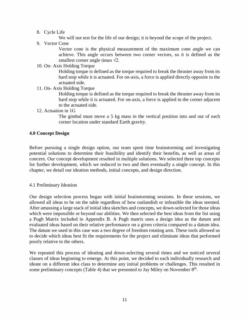
After building a 3D-printed prototype of the design proposed in CDR, we found a few areas for improvement in our design. Figure 28 shows our complete updated design. First, to improve ease of assembly, we flipped the direction of the screws that fastened the thruster plate to the hinge top. This change allows us to assemble the hinge top to the hinge base before fastening the thruster plate to rest of the assembly. Figure 29 shows the assembly change.
0 5 10 15
Time (s)
0
5
10
15
20
25
Volta
ge (V
)
31
Figure 29. Pre-CDR assembly story (left) and post-CDR assembly story (right).
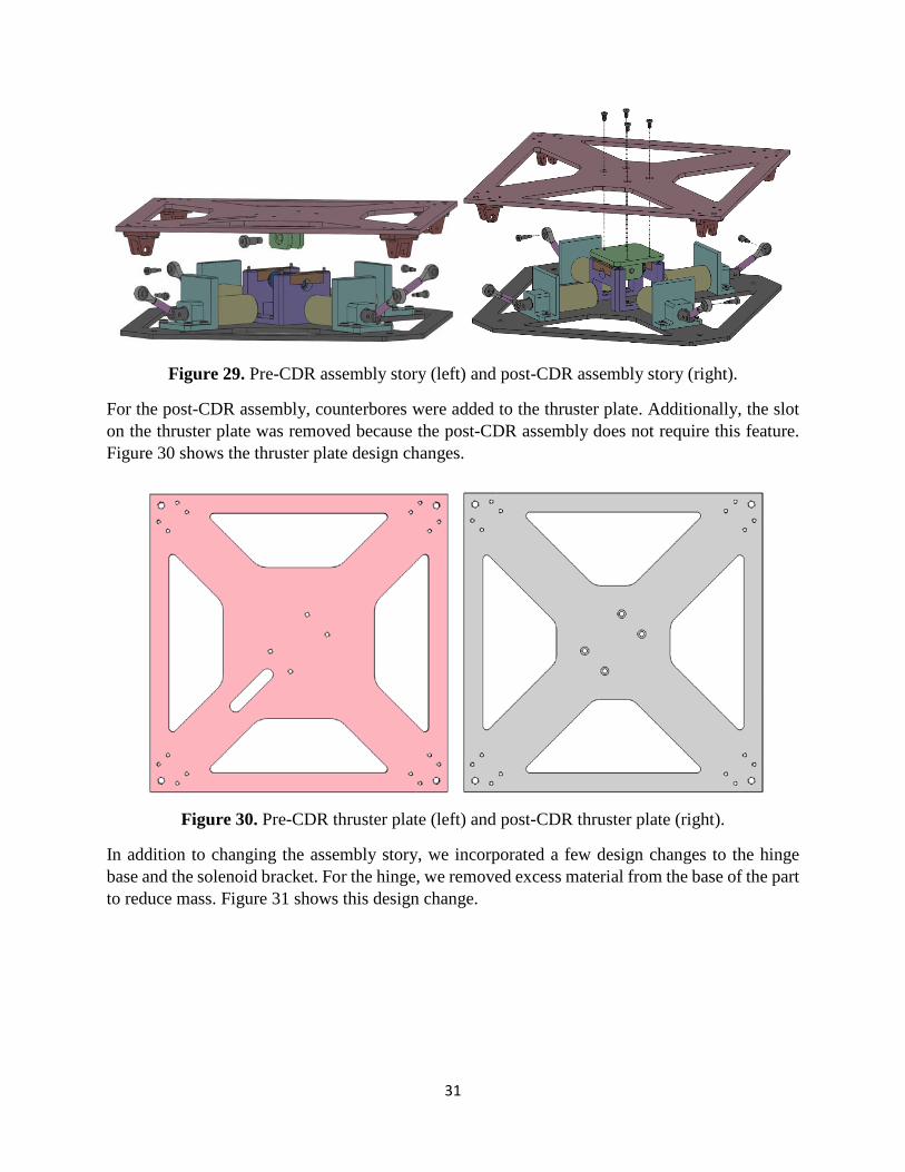
For the post-CDR assembly, counterbores were added to the thruster plate. Additionally, the slot on the thruster plate was removed because the post-CDR assembly does not require this feature. Figure 30 shows the thruster plate design changes.
Figure 30. Pre-CDR thruster plate (left) and post-CDR thruster plate (right).
In addition to changing the assembly story, we incorporated a few design changes to the hinge base and the solenoid bracket. For the hinge, we removed excess material from the base of the part to reduce mass. Figure 31 shows this design change.

32
Figure 31. Pre-CDR hinge base (left) and post-CDR hinge base (right).
For the solenoid bracket, we changed the bolt pattern that mounts to the base plate by reducing the number of clearance holes from four to two, reducing the total part count. Additionally, we changed the hard stop from an angled flat surface to a rounded edge. This allows the hard stop to interface with the thruster plate by means of a line contact, instead of relying on an angled machine surface where full contact is not guaranteed. We also reduced the hard stop wall thickness and removed material from the base of the solenoid bracket to reduce mass. Figure 32 shows these design changes.
Figure 32. Pre-CDR solenoid bracket (left) and post-CDR solenoid bracket (right).
In order to facilitate our testing, we designed two acrylic boxes, a mock thruster and an electronics housing. The mock thruster was designed to simulate the volume and mass properties of an ion thruster. The electronics housing was designed to hold our Arduino and testing board. Both boxes were laser cut out of black acrylic and the internal seams were fixed using hot glue. These designs are shown in Figure 33.

33
Figure 33. Final Gimbal Design with Mock Thruster and Electronics Box
To simulate the mass properties of an ion thruster, 5 kg of mass was added to the mock thruster. The center of mass location was determined in CAD, and foam was be used to raise the weights to the appropriate height. Figure 34 shows the mock thruster with the modeled weights from Cal Poly Mechatronics lab that correctly imitate the center of mass.
Figure 34. Acrylic Mock Thruster with Test Masses for a Similar Center of Gravity
The acrylic base plate of the mock thruster includes bolt patterns for mounting testing equipment. A 3D printed bracket was designed to hold a laser pointer during vector precision testing. These designs are shown in Figure 35 and the assembly of the vector precision test is shown in Figure 36.

34
Figure 35. Mock thruster base plate (left) and laser pointer bracket (right).
Figure 36. Assembly of vector precision test with the active laser pointer.
5.5 Safety, Maintenance, and Repairs
After completing our safety hazard analysis, shown in Appendix H, we found no major safety concerns for our design. Since this gimbal is designed to operate in space, there will be no people

35
to injure in the event of a failure. Additionally, we performed a failure mode analysis and a risk assessment, shown in Appendix I and J respectively, and found no major risks associated with our final design. On the ground, there are some minor concerns during assembly and testing. Those involved should be aware to avoid touching any live wires, since the solenoid will draw current when actuating, particularly at the initial pulse. While the forces are low, the hinge mechanism and the hard stops are pinch points and users should keep their hands clear while actuation is occurring. The gimbal has been designed so that each component can be removed and replaced after testing if necessary. However, it is intended for a satellite and will not receive maintenance over its life cycle, so the gimbal has not been designed to accommodate repairs. 5.6 Cost Analysis
The costs for all components used over the course of this project total to $3,141.56, which is $359.44 below our target budget of $3,500. The full budget for all components purchased over the course of the senior project is included in Appendix K. Table 6 breaks down the cost of all off the shelf components by subsystem, which totals to $405.
Table 6: Off the Shelf Components
Subsystem Cost Hinge $110
Solenoid and Linkage $168 Plates $55
Mock Thruster $72 Total $405
After verifying the kinematics of our design through a kinematic prototype built from off the shelf components and 3D printed parts, we ordered the remaining components which were machined by Protolabs. The costs of these components are broken down by subsystem in Table 7.
Table 7: Protolabs CNC Machined Components Subsystem Cost
Hinge $867 Solenoid and Linkage $1063
Total $1930
The total cost of our confirmation prototype is the sum of the off the shelf and the Protolabs machined components, or about $2,335. The remainder of the spent budget was used for creating our initial and kinematic prototypes.

36
6.0 Manufacturing Plan Our manufacturing occurred in two major steps. First, we manufactured a 3D printed kinematic prototype, using off the shelf components, as a way of verifying our design. Custom parts for this prototype were 3D printed in PLA plastic. After this build was complete and the design finalized, we sent the custom part drawings for our confirmation prototype to Protolabs Inc. to be CNC machined out of aluminum. We manufactured the plates using the water jet in the Cal Poly shops. 6.1 Procurement We sourced the components for the gimbal from McMaster-Carr and DigiKey. The parts list with sources is attached in Appendix K. For the CNC parts, Protolabs supplied the raw stock of 6061 aluminum. 6.2 Manufacturing For our 3D printed design, we utilized a Monoprice MakerSelect V2 3D printer. Each print used black PLA due to its low cost and availability and a 0.1mm layer height. Some features were modified to allow for 3D printing tolerances. We used the laser cutter to cut the plates from clear acrylic. The spring plungers, rod ends, and solenoids were self-threaded into the plastic. Figure 37 shows the final assembled plastic prototype.
Figure 37. Complete 3D-printed prototype
After building and testing the plastic model, we began designing and manufacturing of the metal version. First, we used the IT department water jet to cut-to-cut the plates out of 1/8” 6061 aluminum plate. We created a 2D drawing file to program the path of the jet. The size of each hole was reduced in order to account for the ~1mm width of cut on the water jet. After the plates were cut, they were deburred, and the holes were brought to final size with a drill press. Finally, we used
37
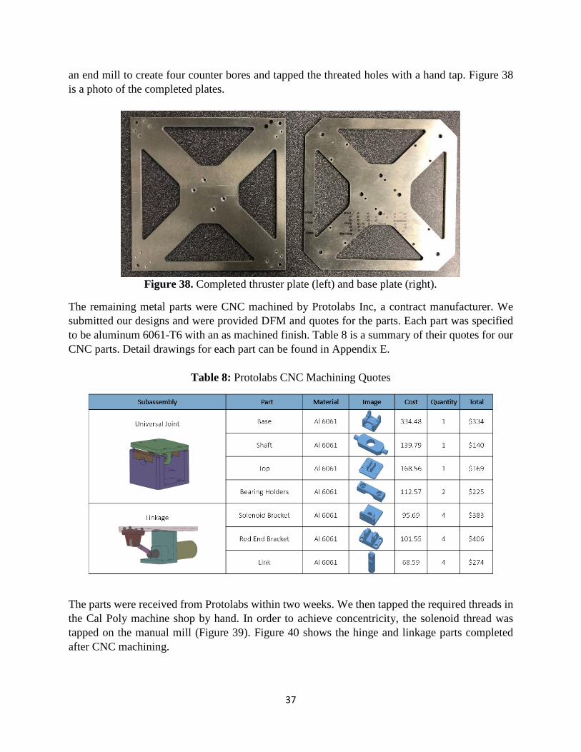
an end mill to create four counter bores and tapped the threated holes with a hand tap. Figure 38 is a photo of the completed plates.
Figure 38. Completed thruster plate (left) and base plate (right).
The remaining metal parts were CNC machined by Protolabs Inc, a contract manufacturer. We submitted our designs and were provided DFM and quotes for the parts. Each part was specified to be aluminum 6061-T6 with an as machined finish. Table 8 is a summary of their quotes for our CNC parts. Detail drawings for each part can be found in Appendix E.
Table 8: Protolabs CNC Machining Quotes
The parts were received from Protolabs within two weeks. We then tapped the required threads in the Cal Poly machine shop by hand. In order to achieve concentricity, the solenoid thread was tapped on the manual mill (Figure 39). Figure 40 shows the hinge and linkage parts completed after CNC machining.

38
Figure 39. Tapping solenoid threads into solenoid bracket
Figure 40: Completed hinge (left) and linkage (right).
Finally, we created a mock thruster and electronics box. We designed an interlocking flat pattern for each box and laser cut it from black acrylic. Each side was glued together internally with hot glue. Figure 41 shows the completed boxes.
Figure 41: Laser cut sides (left), electronics box (center), mock thruster (right)

39
6.3 Assembly We assembled our confirmation prototype manually with a set of English and Metric ball-end hex keys. The gimbal consists of two main subassemblies and one final assembly step. The first main subassembly is the two-axis hinge, depicted in Figure 42. Appendix E lists the parts and specific hardware used. One problem that occurred during assembly of the hinge was the top shims (item #8) would not stay in place during insertion of the hinge top. To fix this problem, we applied superglue to the shim and carefully located it with tweezers before assembling the rest of the parts.
Figure 42. Two-axis hinge assembly
The linkage and solenoid assembly is the second major subassembly, depicted in Figure 43. Appendix E lists the parts and specific hardware used. The spring pin (item #6) and radial bearing (item #8) were press-fit in with a vice. To ensure the correct orientation of the rod end (item #5), we added shims (item #7) until the rod end clocked correctly with the rod end bracket (shown in Figure 43 of the final assembly). We built four linkage and solenoid assemblies before moving on to the final assembly.

40
Figure 43. Linkage and solenoid assembly
Figure 44 depicts the final assembly. We first fastened the two-axis hinge (item #4) and the linkage and solenoid assemblies (item #5) to the base plate (item #1). Then, we fastened the four rod end brackets (item #3) to the thruster plate (item #2) and assembled the thruster plate to the two-axis hinge. Finally, we used shoulder bolts (item #9) to connect the rod end brackets with the linkage and solenoid assemblies. Figures 45 and 46 depicts the completed gimbal assembly.
Figure 44. Final assembly

41
Figure 45. Completed gimbal
Figure 46. Assembled gimbal with the mock thruster
7.0 Design Verification To validate the performance of our gimbal design, we developed a set of tests and design inspections. The results for each specification are included in Table 9. Descriptions of the original specifications can be found in Table 3. These tests were developed using our Design Verification and Testing Plan, found in Appendix L. The thermal-vacuum and life cycle tests were not

42
performed due to logistical issues and non-space grade components used. Our testing scheme focuses on verifying two important aspects of our design. The first set of tests focuses on testing the accuracy and precision of the gimbal. The second set of tests validates the ability of the gimbal to meet the load requirement of positioning an ion thruster. In addition to these tests, we performed design inspections to measure the overall mass and product envelope of the gimbal.
Table 9: Completed Specification Table
Spec. #
Parameter Requirement or Target
Tolerance Value Result
1 Mass 1.5kg Max 0.926kg Pass
2 Product Size 200x200x80mm Max 199x199x44mm Pass
3 Vector Precision ±0.5° Max ±0.01° Pass
4 Cost $3500 Max $2,264 Pass
5 Operational Temperature
-40°C to 100°C Min Not Tested -
6 Survival Temperature
-100°C to 200°C Min Not Tested -
7 Operational in Vacuum
10−8 Pa Min Not Tested -
8 Cycle life 10 Years Min Not Tested -
9 Vector Cone 2.5° Min 2.455° Fail
10 On- Axis Holding Torque
0.2Nm Min 0.25N-m Pass
11 Off-Axis Holding Torque
0.2Nm Min 0.1N-m Fail
12 Actuation in 1G Go/No-go - Pass Pass 7.1 Test #1: Vector Precision by Laser Pointer For this test, we attached a laser pointer with a bracket to the center of our mock thruster. We then fixed the gimbal base plate to the ground so that the laser pointed vertically towards a sheet of paper attached on the ceiling. The setup used for testing is shown in Figure 47. We ran the gimbal through its actuation range and recorded the position of the laser at each position with a pen. This

43
allowed us to measure the spread of the data around a position after repeated tests. We found that the laser center varied by 2mm maximum over a 2.974m distance. This corresponds to a change in corner angle of 0.001° each actuation. We conducted an uncertainty analysis on this measurement, and after factoring in the resolution of the measurement of the height of the ceiling, distance between the projected corners, and the spread of each data set. This resulted in an uncertainty of 0.004°, so we conservatively set the rated uncertainty to 0.01°. One problem with this test is the resolution of the laser pointer. We found that the laser pointer we used had a size of 4mm over this same distance. We plotted the center of the laser pointer beam on the paper to obtain the results, but the fact that the data was completely enclosed by the laser beam is strong evidence for the repeatability of the angle produced by the solenoids.
Figure 47. Laser pointer vector precision testing setup
7.2 Test #2: Vector Precision by Inertial Measurement Unit The second test for verifying vector precision utilized the MPU9250 inertial measurement unit (IMU). We used a script to test each of the four positions and record the position of the IMU after each actuation. Table 10 shows the results of this test. This test did not prove to be useful. The purpose was to determine the repeatability of the actuation angles, but there was a lot of noise affecting the measurement by approximately ±0.3°. Since the IMU noise is larger than our anticipated measurement range, it gives a poor indication of our repeatability. A graph of some of the data is shown in Figure 49 with each horizontal segment is a corner vector. Additionally, the calibration of the IMU proved to be challenging. To calibrate the system with respect to the angle of the table, we removed the thruster plate from the gimbal and placed it on a block of machined aluminum to raise it off the table, aligning it with the edge of the table. We then began the calibration and once the system reached steady state, we zeroed the position. Next, we re-attached the thruster plate to the gimbal and re-aligned the thruster plate with the edge of the table. The program then began actuating and collecting position data.

44
Table 10: Vector Precision IMU Test Results
Average Angle (degrees) Corner Trial 1 Trial 2 % Difference
A 3.333 3.348 0.438 B 3.478 3.565 2.465 C 3.501 3.530 0.817 D 3.252 3.241 0.359
Figure 48. IMU Test variance
Figure 49. IMU angle data for a series of eight actuations
7.3 Test #3: Vector Accuracy by Mechanical Measurement We used the vector accuracy test to determine the actuation range and accuracy of the angles produced by the gimbal and the hard stops. Our goal was to verify whether our gimbal can output a vector 2.5° from a neutral position. For this test, we used calipers to measure the height of each corner of the thruster plate with respect to the base. We calculated the resultant thrust angle for each actuation position. These four vector angles were then used to calculate the radius of the largest cone that our gimbal can guarantee. Table 11 shows the results of this test. From these results, we selected the smallest cone produced by the gimbal, 2.445°, which is 2.2% smaller than the desired cone. We attempted hit the exact nominal value of 2.5° in our design and the accumulated error resulted in the gimbal not meeting this specification. We would advise increasing the nominal angles slightly to ensure the cone angle is always larger than the spec within tolerance.
0
1
2
3
4
5
0 50 100 150 200 250 300
Angl
e (°
)
Data Point Number
Average Angle

45
Table 11: Calculated Vector Cone Angle with Respect to Vertical Position
Corner Smallest Average Vector Cone (°)
Percent Error (%)
1 2.459 -1.656 2 2.457 -1.704 3 2.445 -2.192 4 2.481 -0.778
7.4 Test #4: 1G Operation Test
Astranis asked that the gimbal be operational under 1G conditions with the expected 5 kg load. The mass-correct mock thruster was mounted to the thruster plate using M5 screws. We used a combination of weights and a Styrofoam block to position the center of mass at the same location as the center of mass of the thruster (based on a 5 kg thruster of uniform density), or 55 mm above the thruster plate. This setup is shown in Figure 50. We also found that a fully loaded thruster settled to the neutral position in under 1 second.
Figure 50. Mock thruster with internal space for adding weights and a slot on the side for mounting an IMU to the thruster plate
7.5 Test #5: Torque Test To determine the maximum torque that the gimbal can produce, we mounted the gimbal in place and fixed the thruster plate so that it could not rotate past the horizontal position. A bag was hung on the opposite side of the test solenoid and weights were added incrementally. This configuration is shown in Figure 51. This test used 13.5V and 0.47A, corresponding to full power for the

46
continuous usage setting. The solenoid opposite the weight was actuated. Once thruster plate began to lift from the hard stop, the final weight was recorded. This test was repeated on each of the sides. The lowest mass at which this failure occurred at was 200g, resulting in a maximum torque of 0.25Nm. We also tested the loading on the axis perpendicular to the actuated solenoid. The off-axis holding torque was much lower at 0.1Nm. The width of the hard stop could also be increased to increase the moment arm in the off-axis configuration. When we did our initial test, we had no problems meeting the 0.2Nm torque requirement with one solenoid tested. However, when we returned to do a second round of testing after making some minor positional adjustments, we found that the gimbal was producing significantly less torque than it had previously. We determined that this was due to the solenoid plunger no longer seating fully in the solenoid. Once the plungers were adjusted so that they fully retracted when powered, we again were able to meet the 0.2Nm requirement.
Figure 51. Torque test experimental setup for the in-axis and off axis configurations
7.6 Inspection and Analysis Results
The verification of the remainder of our parameters was done by inspection and analysis. Our mechanism has a mass 0.926 kg, well within our maximum mass parameter of 1.5 kg. The envelope of the gimbal in the neutral position is 199x199x44 mm, with the height gimbal 45% lower than the design envelope. 7.7 Future Testing In the future, a full integration test with the other systems on the satellite would be required. The interactions with the actual ion thruster will be more complex and will need to be tested thoroughly. Basic functionality tests can be conducted using the Operator’s Manual, found in Appendix M.

47
Additionally, environmental tests with aerospace grade components would be required to test the operational and survival temperature ranges. The solenoids that we utilized are not aerospace grade and would need to be replaced. For these tests, the gimbal should be tested in a thermo-vacuum chamber. After the test, the gimbal should be inspected for deformation, mass change, and functionality.
8.0 Project Management
For this project, we used a Gantt chart to track major milestones, create tasks, and allocate responsibility for those tasks to ensure that we met the major milestones. This allowed each team member to know which tasks were most critical and effectively decide which tasks to work on next. For the third quarter, we used the Gantt chart more heavily than in the previous two quarters due to the focus on manufacturing and testing rather than concept development. A copy of the Gantt chart used for this project can be found in Appendix N. Almost all of our major tasks took place during group meetings with the entire team present. During the ideation and design phases when we were developing multiple designs in parallel, we often worked on our own designs individually before bringing them back to the group for evaluation. When writing reports, performing analysis-based tasks, manufacturing, and testing however, we worked together as a group. As such, it was often not necessary to break down tasks like the testing procedures into individual components when all team members were expected to work on the same task. We made all planning decisions by order of next importance, and the Gantt chart served as a record for the tasks that were completed. Overall, we found that although a Gantt chart may be very useful on larger, more disjointed projects with more intermediate goals and milestone, the use of it did not prove critical for this project.
9.0 Conclusions and Recommendations Over the course of this senior design project, we designed and built a gimbal prototype to orient an ion thruster on one of Astranis’ future satellites. This section provides the results of our project in relation to our original specifications and includes our recommendations for future work. 9.1 Results Our gimbal can produce an average vector within a 2.45° by using a combination of 4 angular positions, each with an accuracy of 0.01°. The cone produced by our gimbal is 2.4% below the 2.5° cone that we aimed to produce. On all other parameters, including total mass, cost, and precision, we either met or exceeded the requirements. The gimbal’s holding torque closely matched our calculations at 0.25Nm, but was lower than our specification for an off-axis load. The environment and life targets were out of the scope of the project. With some minor design changes to either the location or height of the hard stops, it is possible to increase the size of the cone. An option would be to slightly reduce the height of the hard stops. In

48
our design, we relied on many shims and clearance fits to tune component positions. In future designs, we recommend that positions are more tightly controlled and permanently fixed. As for working with Astranis, the biggest challenge that we encountered was the initial lack of definition for the project. The project had a considerable amount of design freedom, which both helped and hindered our progress early on. The freedom allowed us to create and test a wide variety of designs. Pursuing multiple parallel paths allowed us to take the insights from one path and apply it to another. However, this open-endedness made it difficult to determine which paths should be cut, which slowed our progress as we approached the Critical Design Review. After that point, we were able to focus on optimizing and improving upon a single design. Another issue that we encountered was that certain requirements for the design, such as the holding torque specification or the inability to spin the thruster, were added several months into the project. While we were able to redesign to meet these new specifications as soon as we received them, a complete set of requirements at the beginning would have been beneficial. We found that the more we communicated with Jay, the better our designs became because of the quick turnaround time for feedback. Before our Preliminary Design Review, we sent a preview of the concepts that we intended to present. Jay informed us of several places where communication had been previously unclear, prompting major improvements before PDR. This feedback also played into our later design decisions. During the CDR design phase, we began creating short PowerPoints for our weekly meetings with Jay. These presentations were brief but allowed us to better communicate recent developments. Additionally, it allowed Jay to provide continuous feedback, so when we presented our CDR, it contained no surprises. We continued this process into the manufacturing and testing phase, although less frequently once the design was locked-in.
Another benefit of working with Jay was the quick turnaround time for ordering parts. We used 3D-printed materials and McMaster-Carr parts to construct our structural and kinematic prototypes. The ability to send Jay a McMaster cart and have all the materials available within two days for constructing the prototypes helped us stay on timeline immensely. Jay was fantastic as a mentor and knowledgeable resource for this project. We would also like to thank professor Schuster for coordinating senior project and for his valuable guidance throughout the year.
9.2 Next Steps
As discussed in Section 7.7, the primary next step would be to perform additional environment and life tests to verify that the gimbal will withstand the space environment for the life cycle of the satellite. In terms of our design, there are many improvements we would suggest. First, we would optimize the thruster plate and the base plate. These components contribute to about half of the weight of the gimbal so present an opportunity for light-weighting. All components could be optimized for mass through stress analysis. We also recommend integrating the hard stops into the hinge. This would allow the gimbal to rest against a hard stop for each axis of rotation, improving stability.

49
This prototype was designed with easily procurable parts so there are several changes that would have to be made for this design to be launch ready. All components, such as bearings, fasteners, and joints, would need to be replaced with aerospace grade components rated for our life and temperature requirements. Also, the aluminum parts should be hard anodized to mitigate damage at contact surfaces. It would be advantageous to work with a vendor to create solenoids optimized for the gimbal. In our design, we relied on many shims and clearance fits to tune component positions. For future designs, we recommend that the positions are more tightly controlled and permanently fixed. Over the course of our critical design and testing, we thought of several concepts for future design exploration. One area for improvement would be actuator selection. Solenoids are simple, reliable, and non-locking, however, they have nonlinear force curves, short actuation distances, and are quite heavy. We suggest an investigation of using two voice coils to replace the four solenoids. Voice coils can be position controlled, they are bidirectional, and they do not hold position when unpowered. We found one feasible voice coil, Moticont model #GVCM-025-029-01. It has similar stroke, force, and power draw, but it is much larger than the solenoids we used. Another possibility is to replace the solenoids with two rotary motors creating a four-bar linkage. In this case the center joint could be replaced with a ball joint. However, to avoid using geared motors, we would need a strong motor operating at stall. We also recommend exploration of the single degree of freedom concept. This design was eliminated due to complicated manufacturing and no passive return, but it has the potential to be a feasible solution. These concepts are depicted in Figure 53.
(a) Voice Coil Actuators (b) Rotary linkage
(c) Single Degree Of Freedom
Figure 53. Proposed Future Iterations

50
9.3 Final Thoughts
The Thruster Gimbal project proved to be an extremely interesting and nuanced problem to solve. We were able to pursue multiple designs in parallel and we enjoyed the freedom and flexibility that this provided. Although we recognize that our design is not launch ready, we are hopeful our discoveries will help motivate the design that is ultimately launched into space. The gimbal prototype that we created using solenoids and vector averaging is a unique solution to orient an ion thruster and we are eager to see how this concept develops in the future.
Appendices: [A] Quality Function Deployment Chart [B] Pugh Matrix [C] Design Refinement Decision Matrix [D] Alternative Designs [E] Drawing Package [F] Product Literature [G] Design Analysis [H] Design Hazard Checklist [I] Failure Modes and Effects Analysis [J] Risk Assessment [K] Project Budget [L] Design Verification Plan and Report [M] Operator’s Manual [N] Gantt Chart

51
References [1] “AMG-LP Low-Profile Direct-Drive Gimbals.” Aerotech, www.aerotech.com/product-
catalog/gimbals-and-optical-mounts/amg-lp.aspx?p=/product-catalog/gimbals-and-optical-mounts.aspx.
[2] COBRA Gimbal 3DOF, High Accuracy, High Reliability Carpal-Wrist Gimbal. COBRA Gimbal 3DOF, High Accuracy, High Reliability Carpal-Wrist Gimbal, www.tethers.com/SpecSheets/Brochure_Gimbal.pdf.
[3] “Interactive G35 Gimbal Model.” NEA Electronics, www.neaelectronics.com/products/gimbals-and-pointing-mechanisms/.
[4] Ion Thruster Gimbal. Ion Thruster Gimbal, www.moog.com/content/dam/moog/literature/Space_Defense/Spacecraft/Spacecraft_Mechanisms/500-764_Ion_Thruster_Gimbal_0414.pdf.
[5] Wood, Brian, et al. “SMART-1 ELECTRICAL PROPULSION STEERING MECHANISM (EPMEC).” European Space Mechanisms and Tribology Symposium, 2001, esmats.eu/esmatspapers/pastpapers/pdfs/2001/wood.pdf.
[6] Haag, Thomas W. Ion Thruster Support and Positioning System. 14 Apr. 1998.
[7] Tilley, Scott W, et al. Spacecraft Attitude Control and Momentum Unloading Using Gimballed and Throttled Thrusters. 20 Sept. 1994.
[8] Goodzeit, Neil Evan, and Santosh Ratan. Gimbaled Thruster Control System. 19 Nov. 2002.
[9] Voigt, Che-Ram S. Mechanism for Thrust Vector Control Using Multiple Nozzles. 2 Sept. 1997.
[10] Charles, Che-Hang, et al. Attitude Slew Methodology for Space Vehicles Using Gimbaled Low-Thrust Propulsion Subsystem. 20 Dec. 2016.
[11] De Rooij, Antonius. SPACEMATDB, Space Materials Database.
[12]“Space and Missile Systems Center Standard, Test Requirements for Launch, Upper-Stage and Apace Vehicles.” United States Air Force Space Command, 5 Sept. 2014.
[13] “General Environmental Verification Standard (GEVS) for GSFC Flight Programs and Projects.” NASA Goddard Space Flight Center, 22 Apr. 2013.
[14] “Standard Test Method for Total Mass Loss and Collected Volatile Condensable Materials from Outgassing in a Vacuum Environment.” American Society for Testing and Materials

Appendix A: Quality Function Development

Appendix B: Pugh Matrix

Appendix C: Design Refinement Decision Matrix
Decision Matrix
Concept Four Linear
Actuators Dual Pivot Double Swivel
Attribute Weight
Complexity 9 5 45 7 63 3 27
Temperature Resistance 7 5 35 5 35 5 35
Mass 8 4 32 7 56 3 24
Cost 4 4 16 6 24 5 20
Vacuum Resistance 6 5 30 5 30 5 30
Redundancy 6 6 36 6 36 7 42
Reliability 10 4 40 6 60 5 50
Time to Manufacture 3 2 6 5 15 2 6
Volume 5 3 15 5 25 3 15
Vector Repeatability 9 7 63 6 54 8 72
Actuation Time 3 8 24 7 21 6 18
Stiffness 4 5 20 4 16 9 36
Power Consumption 8 5 40 8 64 8 64
Cable Management 5 9 45 8 40 1 5
Sum: 447 539 444

Appendix D: Alternative Designs
Concept Description
Single DOF No Rotation Further development of the preliminary single DOF
idea. This design uses a tilted surface beneath the
thruster that rotates independently. This tilted
surface makes sliding contact with a plate attached
to the thruster. The thruster includes a passive
rotary stage made up of a U-joint to prevent it from
rotating about the z-axis.
Double Swivel This design is an iteration of the four-position linear
actuator concept and utilizes vector averaging to
achieve a single vector over time. This concept uses
two solenoids and a ball joint to position the
thruster in four discrete positions. A pyramidal plate
with four surfaces is used to keep the thruster
clocked in one of four positions.
Electromagnetic Locking Positions This design is another iteration of the four-position
linear actuator concept and utilizes vector averaging
to achieve a single vector over time. This concept
uses four electromagnets and a ball joint to position
the thruster in four discrete positions. For this
design an electromagnet is located underneath each
face of a pyramidal plate. The electromagnets are
independently activated to clock the thruster to one
face of the pyramidal surface.
Appendix E: Drawing Package BOM
Assembly Drawing
Part Drawings

Lvl0 Lvl1 Lvl20 1000 Final Assembly1 0100 Base Plate ------ 1 Manuf'd2 89015K18 12”X12” Alum. Plate Al 6061 McMaster 1 27.71 27.71 Received1 0200 Thruster Plate ------ 1 Manuf'd2 89015K18 12”X12” Alum. Plate Al 6061 McMaster 1 27.71 27.71 Received2 0201 Rod End Bracket Al 6061 Protolabs 4 101.55 406.20 Received1 0300 Two-Axis Hinge ------2 0301 Base Al 6061 Protolabs 1 334.48 334.48 Received2 0302 Shaft Al 6061 Protolabs 1 139.79 139.79 Received2 0303 Bearing Holder Al 6061 Protolabs 2 112.57 225.14 Received2 0304 Hinge Top Al 6061 Protolabs 1 168.56 168.56 Received2 57155K352 R156 Ball Bearing Stl Steel McMaster 2 6.32 12.64 Received2 57155K353 R166 Ball Bearing Stl Steel McMaster 2 5.55 11.10 Received2 97022A887 3/16” Shim Stl Steel McMaster 1 Pack 10.04 10.04 Received2 97022A876 3/16” Shim Stl Steel McMaster 1 Pack 7.15 7.15 Received2 N/A 8-36 Spring Plunger Stl Steel CubeSat 4 11.00 44.00 Received2 93615A110 4-40 Socket Head Screw Stl Steel McMaster 1 Pack 5.65 5.65 Received2 90337A184 3/16" Shoulder Screw Stl Steel McMaster 1 7.74 7.74 Received1 0400 Linkage and Solenoid ------2 0401 Solenoid Bracket Al 6061 Protolabs 4 95.69 382.76 Received2 0402 Link Al 6061 Protolabs 4 68.59 274.36 Received2 2024-1074-ND 3/4" Pull Solenoid Stl Steel DigiKey 4 26.50 106.00 Received2 59935K110 Ball Joint Rod End Alloy Steel McMaster 4 7.50 30.00 Received2 92373A140 3/32" Spring Pin Stl Steel McMaster 1 Pack 3.19 3.19 Received2 97022A868 1/8" Shim Stl Steel McMaster 1 Pack 8.42 8.42 Received2 9368T450 5/16" Brass Bearing Bronze McMaster 4 0.59 2.36 Received1 500 Mock Thruster ------2 501 Thruster Base ------ 1 Manuf'd2 502 Thruster Top ------ 1 Manuf'd2 503 Thruster Side ------ 3 Manuf'd2 504 Thruster Side IMU ------ 1 Manuf'd2 505 Thruster Chamfer ------ 4 Manuf'd2 8505K741 12"x12" Acrylic Sheet Acrylic McMaster 3 7.14 21.42 Received1 92220A313 4-40 Socket Head Screw Stl Steel McMaster 1 Pack 9.38 9.38 Received1 93615A210 6-32 Socket Head Screw Stl Steel McMaster 1 Pack 8.57 8.57 Received1 90265A113 3mm Shoulder Screw Stl Steel McMaster 4 3.08 12.32 Received
Total: 2286.69
Status
Indented Bill of Material (BOM)Gimbal Mechanism
Vendor Qty Cost Ttl CostAssembly Part Number Description Matl

4
2
1
9
8 6
3
7
5
8
SCALE: 3:8
NOT TO SCALE: FOR REFERENCE ONLY
ITEM NO. PART NUMBER DESCRIPTION QTY.1 0100 BASE PLATE 12 0200 THRUSTER PLATE 13 0201 ROD END BRACKET 44 0300 TWO-AXIS HINGE SUBASSEMBLY 15 0400 LINKAGE AND SOLENOID SUBASSEMBLY 46 93615A110 4-40 SOCKET HEAD SCREW 167 92220A313 4-40 SOCKET HEAD SCREW 48 93615A210 6-32 SOCKET HEAD SCREW 129 90265A113 3MM SHOULDER SCREW 4
AL6061-T6
5/22/19G. RAMIREZ
AS MACHINEDBREAK EDGES
INTERPRET GEOMETRICTOLERANCING PER: ASME Y14.5
DIMENSIONS ARE IN MMTOLERANCES:X.X 0.2 X.XX 0.10X.XXX 0.050X.X° 0.5° FINAL ASSEMBLY
SHEET 1 OF 1
UNLESS OTHERWISE SPECIFIED:
SCALE: 2:3 WEIGHT:
REVDWG. NO.
BSIZE
TITLE:
NAME DATE
DRAWN
FINISH
MATERIAL
CHECKED
A A
B B
4
4
3
3
2
2
1
1
J. TRAN
1000

1
7
6
9
5
2
8
4
10
3
11
A
A
B
B SECTION A-A SECTION B-B
ITEM NO. PART NUMBER DESCRIPTION QTY.1 0301 HINGE BASE 12 0302 HINGE SHAFT 13 0303 BEARING HOLDER 24 0304 HINGE TOP 15 SR166 3/8" BALL BEARING 26 57155K352 5/16" BALL BEARING 27 97022A887 3/16" SHIM 38 97022A876 3/16" SHIM 29 8495A6 8-36 SPRING PLUNGER 410 93615A110 4-40 SOCKET HEAD SCREW 411 90337A184 SHOULDER BOLT 1
AL6061-T6
5/27/19G.RAMIREZ
AS MACHINEDBREAK EDGES
INTERPRET GEOMETRICTOLERANCING PER: ASME Y14.5
DIMENSIONS ARE IN MMTOLERANCES:X.X 0.2 X.XX 0.10X.XXX 0.050X.X° 0.5°
A A
B B
4
4
3
3
2
2
1
1
TWO-AXIS HINGE
SHEET 1 OF 1
UNLESS OTHERWISE SPECIFIED:
SCALE: 1:1 WEIGHT:
REVDWG. NO.
BSIZE
TITLE:
NAME DATE
DRAWN
FINISH
MATERIAL
CHECKED
0300
5/27/19J.NEIMAN

27
6
5
8
1 4
A
A SECTION A-A
NOTES
1. ADJUST QTY. OF SHIMS (ITEM NO. 6) UNTIL ROD END IS PERPENDICULAR TO BASE OF SOLENOID BRACKET
ITEM NO. PART NUMBER DESCRIPTION QTY.1 0401 SOLENOID BRACKET 12 0402 LINK 14 195204-230 PULL SOLENOID 15 59935K11 BALL JOINT ROD END 16 92373A140 3/32" SPRING PIN 17 97022A868 1/8" SHIM AS REQ.8 9368T45 5/16" BRASS BEARING 1
AL6061-T6
5/27/19G. RAMIREZ
AS MACHINEDBREAK EDGES
INTERPRET GEOMETRICTOLERANCING PER: ASME Y14.5
DIMENSIONS ARE IN MMTOLERANCES:X.X 0.2 X.XX 0.10X.XXX 0.050X.X° 0.5°
A A
B B
4
4
3
3
2
2
1
1
LINKAGE AND SOLENOID
SHEET 1 OF 1
UNLESS OTHERWISE SPECIFIED:
SCALE: 1:1 WEIGHT:
REVDWG. NO.
BSIZE
TITLE:
NAME DATE
DRAWN
FINISH
MATERIAL
CHECKED J. NEIMAN
0400

4X 3.80 THRU
4X 2.26 6.004-40 UNC 5.69
4X 3.45 15.008-36 UNF 8.33
19.00
35.00
35.18
17.88
R4.839
4X 25.800
2X 27.18
18.0
26.00
R4.839
4X R0.80 MAX
.05
D
3.50
27.178
33.00
R0.05 TYP
2.5 X 45° TYP
0.1 A B C
A
43.18
43.18
35.18
35.18
4X 4.76 22.86
2X 27.2
0.2 A B CC
B4X 2.5 X 45°
4 SURFACES NO BURRS ALLOWED
0.2 A B C
0.2 M A B C
0.1 D
0.1 A B C
.05
AL6061-T6
2/27/19J. NEIMAN
AS MACHINEDBREAK EDGES
INTERPRET GEOMETRICTOLERANCING PER: ASME Y14.5
DIMENSIONS ARE IN MMTOLERANCES:X.X 0.2 X.XX 0.10X.XXX 0.050X.X° 0.5°
A A
B B
4
4
3
3
2
2
1
1
HINGE BASE
04SHEET 1 OF 1
UNLESS OTHERWISE SPECIFIED:
SCALE: 2:3 WEIGHT:
REVDWG. NO.
BSIZE
TITLE:
NAME DATE
DRAWN
FINISH
MATERIAL
CHECKED M. MILICH 2/29/19
0301
SOLIDWORKS Educational Product. For Instructional Use Only.

6.35
11.43
5.72
3.18 2X 4.763
8.128+-0.0100.040 THRU
2X R0.25MAX
12.700
2X 5.08 25.40
2X 0.25 X 45° MAX CHAMFER
4X 2.54 X 45° CHAMFER
0.1 B
A
B
A A
B B
2
2
1
1
AL6061-T6
HINGE SHAFT
01SHEET 1 OF 1
3/3/19J. NEIMAN
UNLESS OTHERWISE SPECIFIED:
SCALE: 2:1
REVDWG. NO.
ASIZE
TITLE:
NAME DATE
CHECKED
DRAWN
AS MACHINEDBREAK EDGES
FINISH
MATERIAL
INTERPRET GEOMETRICTOLERANCING PER: ASME Y14.5
DIMENSIONS ARE IN MMTOLERANCES:X.X 0.2 X.XX 0.10X.XXX 0.050X.X° 0.5°
J. NEIMAN
0302

.70.18
2X .13 1.00 .22 .14
.16
A
B
.529
R.193 0.380 R.13 THRU
1.06
0.1 C A
.28
.32
2X 0.3 X 45° CHAMFER
C
0.2 A B
A A
B B
2
2
1
1
AL6061-T6
BEARING HOLDER
02SHEET 1 OF 1
3/07/19J. NEIMAN
UNLESS OTHERWISE SPECIFIED:
SCALE: 2:1
REVDWG. NO.
ASIZE
TITLE:
NAME DATE
CHECKED
DRAWN
AS MACHINEDBREAK EDGES
FINISH
MATERIAL
INTERPRET GEOMETRICTOLERANCING PER: ASME Y14.5
DIMENSIONS ARE IN MMTOLERANCES:X.X 0.2 X.XX 0.10X.XXX 0.050X.X° 0.5°
J. NEIMAN
0303

3.45 THRU8-32 UNC THRU
4.83 3.0
8.47 0.15 2X10.2 2X 20.32
21.57
12.192
4X 2.5 X 45° CHMAFER
C
3.30
6.890
2X 2.91
1.91
21.59
19.18
A
B 43.18
43.18
4X 3.66 THRU
35.00
19.00 4X 3.5 X 45° CHMAFER0.2 B C A
0.2 C
A A
B B
2
2
1
1
AL6061-T6
HINGE TOP
02SHEET 1 OF 1
3/07/19J. NEIMAN
UNLESS OTHERWISE SPECIFIED:
SCALE: 1:1
REVDWG. NO.
ASIZE
TITLE:
NAME DATE
CHECKED
DRAWN
AS MACHINEDBREAK EDGES
FINISH
MATERIAL
INTERPRET GEOMETRICTOLERANCING PER: ASME Y14.5
DIMENSIONS ARE IN MMTOLERANCES:X.X 0.2 X.XX 0.10X.XXX 0.050X.X° 0.5°
J. NEIMAN
0304

4X R2.0
26.00
9.00
2X 3.18
.05
A
3.18
18.18
R1.59
33.757
35.0
3.50
R3.0 X2 28.00
2X 3.80
15.88
0.2 M A B C
CB
13.10 11.43 9/16-18 UNF 11.0
9.63 THRU
9.90
17.50
0.1 A C
0.1 A B C
A A
B B
2
2
1
1
AL6061-T6
SOLENOID BRACKET
01SHEET 1 OF 1
03/06/19
5/22/19
J. TRAN
UNLESS OTHERWISE SPECIFIED:
SCALE: 3:2
REVDWG. NO.
ASIZE
TITLE:
NAME DATE
CHECKED
DRAWN
AS MACHINEDBREAK EDGES
FINISH
MATERIAL
INTERPRET GEOMETRICTOLERANCING PER: ASME Y14.5
DIMENSIONS ARE IN MMTOLERANCES:X.X 0.2 X.XX 0.10X.XXX 0.050X.X° 0.5°
J. NEIMAN
0401

M3X0.5 8.000.1 A
20.83 2.79
R2.4
4.80
BA
2.04
2X 6.10
2X 45° 1.02
A A
B B
2
2
1
1
AL6061-T6
LINK
3SHEET 1 OF 1
3/7/19G. RAMIREZ
UNLESS OTHERWISE SPECIFIED:
SCALE: 4:1
REVDWG. NO.
ASIZE
TITLE:
NAME DATE
CHECKED
DRAWN
AS MACHINEDBREAK EDGES
FINISH
MATERIAL
INTERPRET GEOMETRICTOLERANCING PER: ASME Y14.5
DIMENSIONS ARE IN MMTOLERANCES:X.X 0.2 X.XX 0.10X.XXX 0.050X.X° 0.5°
G. RAMIREZ
0402

3.50
6.7
5.75 8.50
17.75
6.50
C
13.00 16.5
3.30 3.05.40 1.5
M2x0.4 THRU 4X R1.5
7.25
2x 16°
14.50
23.50
4X R2.5
17.90
8.90
2.80 2.80
3.26 THRU 0.1 A B
B
A
A A
B B
2
2
1
1
AL6061-T6
ROD END BRACKET
3SHEET 1 OF 1
3/3/2019G. RAMIREZ
UNLESS OTHERWISE SPECIFIED:
SCALE: 2:1
REVDWG. NO.
ASIZE
TITLE:
NAME DATE
CHECKED
DRAWN
AS MACHINEDBREAK EDGES
FINISH
MATERIAL
INTERPRET GEOMETRICTOLERANCING PER: ASME Y14.5
DIMENSIONS ARE IN MMTOLERANCES:X.X 0.2 X.XX 0.10X.XXX 0.050X.X° 0.5°
G. RAMIREZ
0201

34.99
19.00
26.00
8xR12.7
4X 2.71 THRU ALL6-32 UNC THRU ALL
16X 2.71 THRU ALL6-32 UNC THRU ALL
4X 4.20 THRU ALLM5 - 6H THRU ALL
8xR3.5
8xR2.5
4X 5.16 THRU ALL
45° 12.0 38.0 40.0
114.3
35.18
78.40
109.60
125.16
13.00
A B
C
3.18 200.00
200.00
0.2 A B
0.2 A B
0.2 A B
0.2 A B
AL6061-T6
2/27/19M. MILICH
AS MACHINEDBREAK EDGES
INTERPRET GEOMETRICTOLERANCING PER: ASME Y14.5
DIMENSIONS ARE IN MMTOLERANCES:X.X 0.2 X.XX 0.10X.XXX 0.050X.X° 0.5°
A A
B B
4
4
3
3
2
2
1
1
BASE PLATE
01SHEET 1 OF 1
M. MILICH
UNLESS OTHERWISE SPECIFIED:
SCALE: 1:2 WEIGHT:
REVDWG. NO.
BSIZE
TITLE:
NAME DATE
DRAWN
FINISH
MATERIAL
CHECKED
0100

8.0
19.00
2XR4.00
34.0
130.81
115.558.90
17.90
35.00
4X 4.20 THRU ALLM5 - 6H THRU ALL
16X 2.26 THRU ALL4-40 UNC THRU ALL
4X 2.71 THRU ALL6-32 UNC THRU ALL
12.7 36.5 43.0
114.3
8XR12.70
2XR2.54
30.0
30.0
2X45°
0.2 A BA
B
C
200.00
3.18 200.00
SLOT DIMENSIONS IN ALL FOUR PLACES
0.2 A B
0.2 A B
AL6061-T6
3/7/19M. MILICH
AS MACHINEDBREAK EDGES
INTERPRET GEOMETRICTOLERANCING PER: ASME Y14.5
DIMENSIONS ARE IN MMTOLERANCES:X.X 0.2 X.XX 0.10X.XXX 0.050X.X° 0.5°
A A
B B
4
4
3
3
2
2
1
1
THRUSTER PLATE
01SHEET 1 OF 1
M. MILICH
UNLESS OTHERWISE SPECIFIED:
SCALE: 1:2 WEIGHT:
REVDWG. NO.
BSIZE
TITLE:
NAME DATE
DRAWN
FINISH
MATERIAL
CHECKED
0200


NUMBERPART
Information in this drawing is provided for reference only.
http://www.mcmaster.com
9.80 mm
25 mm
30.15 mm
14 mmM3 x 0.5 Thread
4 mm
6.40 mm
30° Max.Ball Swivel
3 mm
59935K11Right-Hand Thread
Note:Steel Housing and Ball
Ball Joint Rod End© 2017 McMaster-Carr Supply Company

NUMBERPART
Information in this drawing is provided for reference only.
http://www.mcmaster.com
0.377"
0.3135" +0.001 -0.000
+0.001 -0.000 1/4"±0.005
9368T45High-Temperature Dry-Running
Sleeve Bearing© 2017 McMaster-Carr Supply Company

NUMBERPART
Information in this drawing is provided for reference only.
http://www.mcmaster.com
0.3125"
0.1875" +0.0000 -0.0002
+0.0000 -0.0002 7/64" +0.000
-0.001
Trade Number: R156
57155K352Stainless Steel
Ball Bearing© 2017 McMaster-Carr Supply Company

NUMBERPART
Information in this drawing is provided for reference only.
http://www.mcmaster.com
2 mmHex
5 mm 2 mm
2 mm
4 mm
0.76 mm
1.3 mm
6 mm
3 mm
M2 x 0.4 mm Thread
-0.010-0.072
+0.25+0.00
90265A113Metric 18-8 Stainless Steel
Shoulder Screw© 2018 McMaster-Carr Supply Company

NUMBERPART
Information in this drawing is provided for reference only.
http://www.mcmaster.com
3/32"Hex
5/16" 7/64"
0.164"
0.047"
3/16"+-0.0000.001
0.119"
3/16" 5/16"+-0.0020.000
#8-32 Thread
90337A184Low-Profile
Precision Shoulder Screw© 2018 McMaster-Carr Supply Company

NUMBERPART
Information in this drawing is provided for reference only.
http://www.mcmaster.com
0.099"
0.022"Wall Thickness
3/32"Nominal Pin
Diameter
Actual PinDiameter
5/16" ±0.015
0.091"
Chamfer length variesfrom 0.008" to 0.038"
in length.
+0.004 -0.000
92373A14018-8 Stainless SteelSlotted Spring Pin
© 2011 McMaster-Carr Supply CompanyRecommended 0.094" to 0.097" Diameter Hole Size

NUMBERPART
Information in this drawing is provided for reference only.
http://www.mcmaster.com
0.183"
0.05"Hex
0.112"
0.059" 1/4"
#4-40 Thread
93615A110Low-Profile Stainless SteelSocket Head Cap Screw
© 2019 McMaster-Carr Supply Company

NUMBERPART
Information in this drawing is provided for reference only.
http://www.mcmaster.com
0.226"
1/16"Hex
0.138"
0.072" 1/4"
#6-32 Thread
93615A210Low-Profile Stainless SteelSocket Head Cap Screw
© 2014 McMaster-Carr Supply Company

NUMBERPART
Information in this drawing is provided for reference only.
http://www.mcmaster.com
3/16"±0.002
1/8" -0.000+0.011
0.003"±0.0005
97022A868316 Stainless Steel
Round Shim© 2017 McMaster-Carr Supply Company
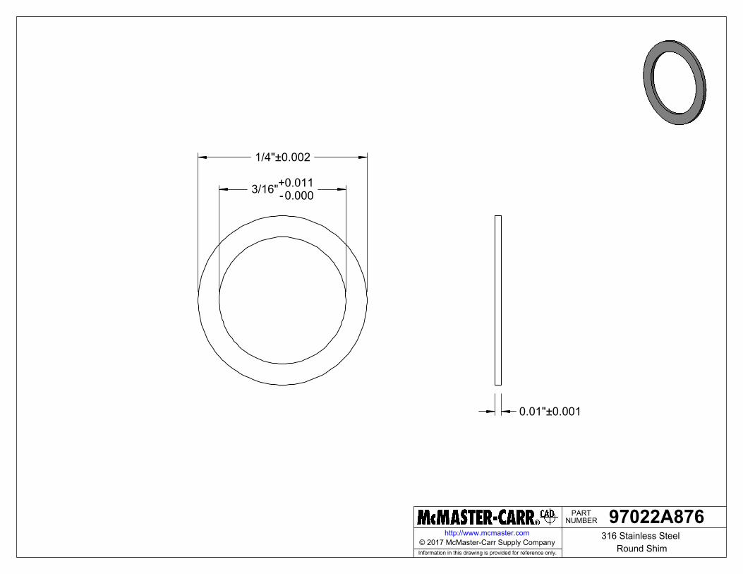
NUMBERPART
Information in this drawing is provided for reference only.
http://www.mcmaster.com
1/4"±0.002
3/16"-0.000+0.011
0.01"±0.001
97022A876316 Stainless Steel
Round Shim© 2017 McMaster-Carr Supply Company
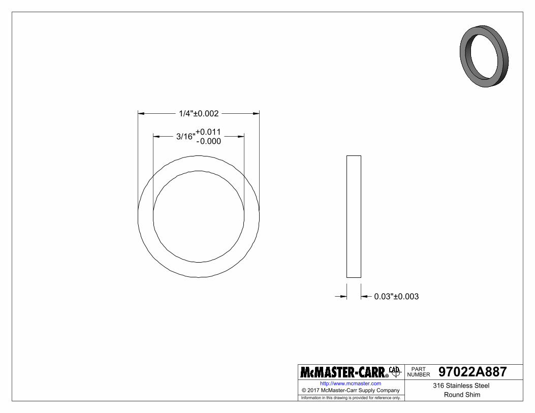
NUMBERPART
Information in this drawing is provided for reference only.
http://www.mcmaster.com
1/4"±0.002
3/16"-0.000+0.011
0.03"±0.003
97022A887316 Stainless Steel
Round Shim© 2017 McMaster-Carr Supply Company
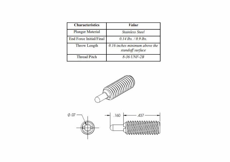

Specifications
Bearing Type Open
Bore Dia (d) 0.1875 in
Outer Dia (D) 0.3750 in
Width (B) 0.1250 in
Radius (min) (rs) 0.004 in
Dynamic Load Rating (Cr) 136 lbs
Static Load Rating (Cor) 49 lbs
Max Speed (Grease) 50,000 rpm
Max Speed (Oil) 60,000 rpm
Max. Shaft Shoulder Dia. Inner (Li) 0.2 in
Min. Housing Shoulder Dia., Outer (Lo) 0.3 in
Ball Qty 8
Ball Dia (Dw) 0.0625 in
Weight (g) 0.81 grams
Precision A1
Standard Clearance K25
Material Martensitic Stainless Steel
* Also available in 52100 Chrome Steel
* ABEC Grades 1, 3, 5, 7, and 9 are available.
Part Number: SR166Miniature & InstrumentSeries, Stainless Steel BallBearing
Product Details
Value Beyond the Part™All information in this catalog has been thoroughly checked for accuracy. However, AST Bearings assumes no liability for possible
errors or omissions. All dimensions and specifications are subject to change without notice.
HEADQUARTERS:222 New RoadParsippany, NJ 07045(800) 526-1250
WEST COAST OFFICE:3740 Prospect AveYorba Linda, CA 92886(800) 227-8786
email:[email protected]
Engineering Consulting & Design
Bearing Applications Engineering
Quality Assurance Inspection &Verification
Bearing Failure Analysis
Custom Packaging
Bearing Lubrication Services

Appendix F: Product Literature

Product LiteratureCal Poly Thruster Gimbal
Description Manufacturer Part # Component Literature Links
Pull Solenoid DigiKey 2024-1074-ND Solenoidhttps://www.digikey.com/products/en?
keywords=2024-1074-NDRod End McMaster 59935K110 Linkage https://www.mcmaster.com/59935k11
3/32” Spring Pin McMaster 92373A140 Solenoid https://www.mcmaster.com/92373a1408”X8” Aluminum Plate McMaster 89015K239 Plates https://www.mcmaster.com/89015k239
3/16” Shim McMaster 97022A887 Hinge https://www.mcmaster.com/97022a8873/16” Shim McMaster 97022A876 Hinge https://www.mcmaster.com/97022a8761/8” Shim McMaster 97022A868 Linkage https://www.mcmaster.com/97022a868
3/8" Bearing AST Bearings SR166 Hingehttps://www.astbearings.com/catalog.
html?page=product&id=SR1665/16” Ball Bearing McMaster 57155k352 Hinge https://www.mcmaster.com/57155k352
5/16” Bronze Bearing McMaster 9368T450 Solenoid https://www.mcmaster.com/9368t45
Spring Plunger CubeSat N/A Hinge
https://static1.squarespace.com/static/5418c831e4b0fa4ecac1bacd/t/56e9b62337013b6c063a655a/1458157
095454/cds_rev13_final2.pdf3/16” Shoulder Screw McMaster 90337A184 Hinge https://www.mcmaster.com/90337a1843mm Shoulder Screw McMaster 90265A113 Linkage https://www.mcmaster.com/90265a113
Socket Head Screw 6-32 McMaster 93615A210 Various https://www.mcmaster.com/93615a210Socket Head Screw 4-40 McMaster 93615A110 Various https://www.mcmaster.com/93615a110

Appendix G: Design Analysis Calculations


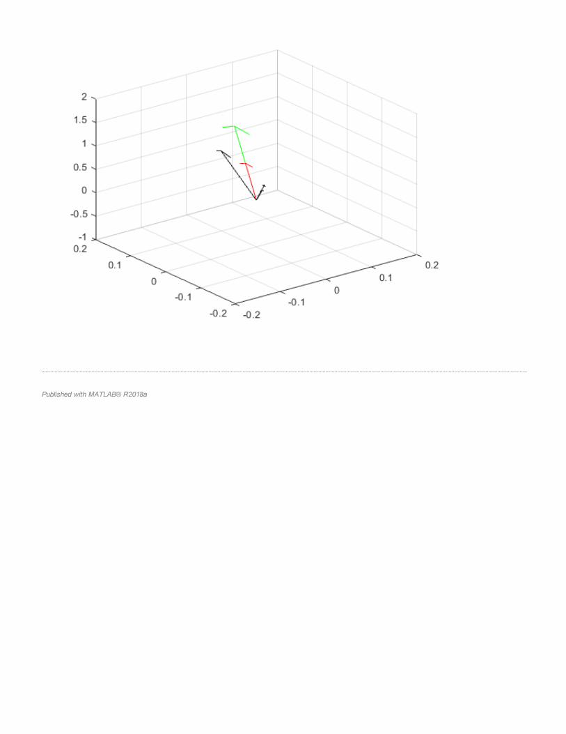

Appendix H: Design Hazard Checklist
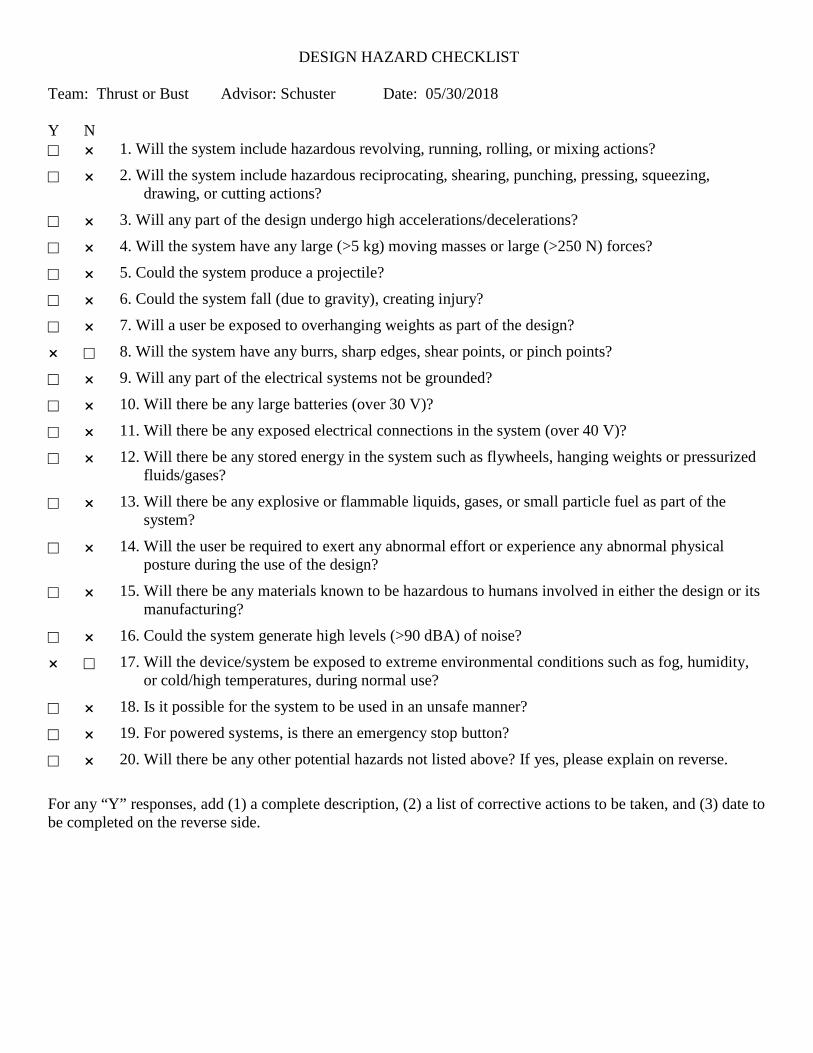
DESIGN HAZARD CHECKLIST Team: Thrust or Bust Advisor: Schuster Date: 05/30/2018 Y N 1. Will the system include hazardous revolving, running, rolling, or mixing actions? 2. Will the system include hazardous reciprocating, shearing, punching, pressing, squeezing,
drawing, or cutting actions? 3. Will any part of the design undergo high accelerations/decelerations? 4. Will the system have any large (>5 kg) moving masses or large (>250 N) forces? 5. Could the system produce a projectile? 6. Could the system fall (due to gravity), creating injury? 7. Will a user be exposed to overhanging weights as part of the design? 8. Will the system have any burrs, sharp edges, shear points, or pinch points? 9. Will any part of the electrical systems not be grounded? 10. Will there be any large batteries (over 30 V)? 11. Will there be any exposed electrical connections in the system (over 40 V)? 12. Will there be any stored energy in the system such as flywheels, hanging weights or pressurized
fluids/gases? 13. Will there be any explosive or flammable liquids, gases, or small particle fuel as part of the
system? 14. Will the user be required to exert any abnormal effort or experience any abnormal physical
posture during the use of the design? 15. Will there be any materials known to be hazardous to humans involved in either the design or its
manufacturing? 16. Could the system generate high levels (>90 dBA) of noise? 17. Will the device/system be exposed to extreme environmental conditions such as fog, humidity,
or cold/high temperatures, during normal use? 18. Is it possible for the system to be used in an unsafe manner? 19. For powered systems, is there an emergency stop button? 20. Will there be any other potential hazards not listed above? If yes, please explain on reverse. For any “Y” responses, add (1) a complete description, (2) a list of corrective actions to be taken, and (3) date to be completed on the reverse side.

Description of Hazard Planned Corrective Action Planned Date
Actual Date
May have sharp edges or pinch points.
Break edges and inform operator of potential pinch points, if any exist for the chosen design.
5/15/19 5/9/19
The mechanism will be operated in space.
No corrective action is required because the mechanism will only be exposed to extreme environments once in space.
N/A
There is no “Emergency Stop” button.
No corrective action is required because the voltage and current will be very low, and the power supply will have a button to suppress output.
N/A

Appendix I: Failure Modes and Effects Analysis

Product: THRUSTER GIMBAL
Team: THRUST OR BUST
Design Failure Mode and Effects AnalysisPrepared by: MILENA MILICH
Date: 03/07/2019
Design FMEA_Linkage.xlsx Page 1 of 1 Revision Date: 5/7/19
Action Results
System / Function Potential Failure Mode
Potential Effects of the Failure Mode
Seve
rity
Potential Causes of the Failure Mode
Current Preventative
Activities
Occ
uren
ce Current Detection Activities De
tect
ion
Prio
rity
Recommended Action(s)Responsibility &
Target Completion Date
Actions Taken
Seve
rity
Occ
uren
ce
Criti
calit
y
Thruster plate/ hold thruster secure thruster becomes loose a) lose accuracy
b) lose thruster 8 1) bolt failure2) vibe backout
1) load and bolt analysis (pretorque, etc)2) staking
2 Visual detection 4 64
1) Position sensor on the thruster2) Satellite position feedback
1) J. Tran (5/9/19)2) N/A
Holes added to thruster plate for mounting IMU
Base plate/ secure mechanism to satellite
thruster and mechanism become loose
a) lose accuracyb) lose thruster 9 1) bolt failure
2) vibe backout
1) load and bolt analysis (pretorque, etc)2) staking
2 None 4 72
1) Position sensor on the thruster2) Satellite position feedback
1) J. Tran (5/9/19)2) N/A
Holes added to thruster plate for mounting IMU
Base plate/ hold cables cable wear a) lose power to the
thruster or solenoids 7 1) cable sliding against edge of one of the plates
1) cable management2) chamfer or break edges
4 Visual inspection 2 56 None
Hinge top/ rotate about shaft Joint locks a) thruster motion limited
to one plane 6 1) Uneven thermal expansion 1) use bearings 3 Visual inspection 2 36 None
Hinge top/ hold thruster plate secure thruster becomes loose a) lose accuracy
b) lose thruster 8 1) bolt failure2) vibe backout
1) load and bolt analysis (pretorque, etc)2) staking
2 Visual inspection 4 64 None
Hinge shaft/ rotate in hinge Joint locks a) thruster motion limited
to one plane 6 1) Uneven thermal expansion 1) use bearings 3 Visual inspection 2 36 None
Solenoid bracket/hold solenoid
Solenoid no longer held in position
a) Lose positioing ability in half the cone 5
1) bracket deforms under high moment2) bracket breaks under moment at extreme temperatures
1) limit solenoid force 1 Visual inspection 2 10 None
Solenoid/pull on linkage Lose power
a) lose thruster positioning in half of the cone
51) cable wear2) out of temperature range
1) cable management 5 Visual inspection 2 50 None
Solenoid pin becomes stuck to solenoid
a) thruster becomes stuck at one angle 7 1) Large radial force at
extreme temperatures1) add bearing to take some of the load 4 Visual inspection 2 56 None
Spring pin/ hold link to solenoid (allowing rotation)
Joint locks a) Thruster becomes stuck at one angle 7 1) Uneven thermal
expansion 1) None 4 Visual inspection 2 56 None
Pin breaks a) Thruster becomes stuck at one angle 7 1) Large actuation forces 1) limit solenoid force 4 Visual inspection 2 56 None
Rod end/ allow rotation Joint locks a) Thruster becomes stuck at one angle 7 1) Uneven thermal
expansion 1) None 4 Visual inspection 2 56 None
Linkage bracket/ hold rod end to thruster plate
Joint locks a) Thruster becomes stuck at one angle 7 1) Uneven thermal
expansion 1) None 4 Visual inspection 2 56 None
Linkage detatches from thruster plate
a) Lose positioing ability in half the cone 5 1) bolt failure
2) vibe backout
1) load and bolt analysis (pretorque, etc)2) staking
2 Visual inspection 4 40 None
Spring plungers/ return thruster to center Lose of restoring force a) Loss of passive return
to center 5 1) loss of stiffness2) vibe backout
1) use parts with aerospace heritage2) Loctite
3 Testing 6 90
1) Position sensor on the thruster2) Satellite position feedback
1) J. Tran (5/9/19)2) N/A
Holes added to thruster plate for mounting IMU

Appendix J: Risk Assessment

Preliminary Risk Assesment 4/30/2019
designsafe Report
Application: Preliminary Risk Assesment Analyst Name(s): Thrust or Bust
Description: Company: Cal Poly San Luis Obispo
Facility Location:Product Identifier: Thruster Gimbal Mechanism
Assessment Type: Detailed
Limits:
Sources:
Risk Scoring System: ANSI AIHA Z10 2005
Guide sentence: When doing [task], the [user] could be injured by the [hazard] due to the [failure mode].
/CommentsHazard /
Task
User /
Failure Mode
Risk Reduction Methods
ResponsibleInitial Assessment
Severity
LIkelihood of Oc Risk Level
Final Assessment
Severity
LIkelihood of Oc Risk Level/Control System /ReferenceItem Id
Status /
pinch points : between
thruster plate and gimbal
misuse (placing hands near
mechanism during operation)
LowNegligible
Occasional
Negligible
Occasional
Low
/Standard preocedures
for testing and operation
will be created by the
team once the prototype
is manufactured (TYP)
operator(s)
normal operation
1-1-1
electrical / electronic :
normally live parts(direct
contact)
loose wires
MediumMarginal
Occasional
standard procedures Marginal
Improbable
Low In-process
Team
operator(s)
normal operation
1-1-2
electrical / electronic :
software errors
unexpected actuation
LowNegligible
Remote
Negligible
Remote
Lowoperator(s)
normal operation
1-1-3
heat / temperature : burns /
scalds
extended use of solenoids
MediumMarginal
Occasional
warning label(s) Marginal
Remote
Medium Action Item [5/23/2019]
Milena
operator(s)
normal operation
1-1-4
mechanical : unexpected
motion
device not powered off
LowNegligible
Remote
Negligible
Remote
Lowoperator(s)
clear jams
1-2-1
pinch points : between
thruster plate and gimbal
device not powered off
LowNegligible
Remote
Negligible
Remote
Lowoperator(s)
clear jams
1-2-2
Privileged and Confidential InformationPage 1

Preliminary Risk Assesment 4/30/2019
/CommentsHazard /
Task
User /
Failure Mode
Risk Reduction Methods
ResponsibleInitial Assessment
Severity
LIkelihood of Oc Risk Level
Final Assessment
Severity
LIkelihood of Oc Risk Level/Control System /ReferenceItem Id
Status /
pinch points : between
thruster plate and gimbal
not moving hands away
during operation
LowNegligible
Occasional
Negligible
Occasional
Lowtechnician(s)
trouble-shooting / problem
solving
2-1-1
electrical / electronic :
normally live parts(direct
contact)
loose wires
MediumMarginal
Occasional
standard procedures Marginal
Improbable
Low In-process
Team
technician(s)
trouble-shooting / problem
solving
2-1-2
heat / temperature : hot
surfaces
extended use of solenoids
MediumMarginal
Occasional
warning label(s) Marginal
Remote
Medium Action Item [5/23/2019]
Milena
technician(s)
trouble-shooting / problem
solving
2-1-3
mechanical : unexpected
motion
software or wiring errors
MediumNegligible
Probable
standard procedures Negligible
Remote
Low In-process
Team
technician(s)
adjust controls / switches
2-2-1
mechanical : unexpected
motion
device not powered off
LowNegligible
Occasional
Negligible
Occasional
Lowengineer(s)
adjust controls
3-1-1
pinch points : between
thruster plate and gimbal
misuse (placing hands near
mechanism during operation)
LowNegligible
Occasional
Negligible
Occasional
Lowengineer(s)
adjust controls
3-1-2
electrical / electronic :
normally live parts(direct
contact)
loose wires
MediumMarginal
Occasional
standard procedures Marginal
Improbable
Low In-process
Team
engineer(s)
adjust controls
3-1-3
heat / temperature : burns /
scalds
contact with solenoids before
they are allowed to cool
MediumMarginal
Occasional
warning label(s) Marginal
Remote
Medium Action Item [5/23/2019]
Milena
engineer(s)
adjust controls
3-1-4
pinch points : between
thruster plate and gimbal
misuse (placing hands near
mechanism during operation)
LowNegligible
Occasional
Negligible
Occasional
Lowpasser-by / non-user
walk near robot
4-1-1
Privileged and Confidential InformationPage 2

Appendix K: Project Budget
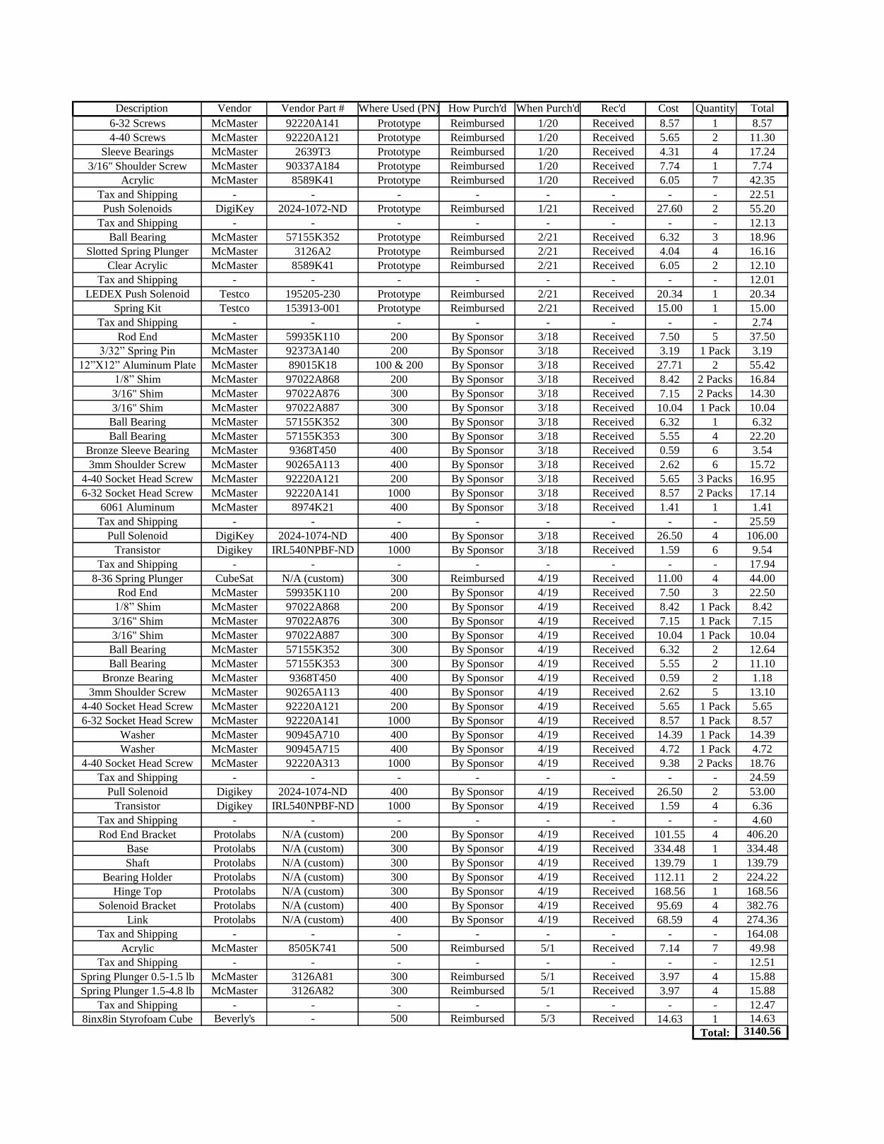
Description Vendor Vendor Part # Where Used (PN) How Purch'd When Purch'd Rec'd Cost Quantity Total
6-32 Screws McMaster 92220A141 Prototype Reimbursed 1/20 Received 8.57 1 8.57
4-40 Screws McMaster 92220A121 Prototype Reimbursed 1/20 Received 5.65 2 11.30
Sleeve Bearings McMaster 2639T3 Prototype Reimbursed 1/20 Received 4.31 4 17.24
3/16" Shoulder Screw McMaster 90337A184 Prototype Reimbursed 1/20 Received 7.74 1 7.74
Acrylic McMaster 8589K41 Prototype Reimbursed 1/20 Received 6.05 7 42.35
Tax and Shipping - - - - - - - - 22.51
Push Solenoids DigiKey 2024-1072-ND Prototype Reimbursed 1/21 Received 27.60 2 55.20
Tax and Shipping - - - - - - - - 12.13
Ball Bearing McMaster 57155K352 Prototype Reimbursed 2/21 Received 6.32 3 18.96
Slotted Spring Plunger McMaster 3126A2 Prototype Reimbursed 2/21 Received 4.04 4 16.16
Clear Acrylic McMaster 8589K41 Prototype Reimbursed 2/21 Received 6.05 2 12.10
Tax and Shipping - - - - - - - - 12.01
LEDEX Push Solenoid Testco 195205-230 Prototype Reimbursed 2/21 Received 20.34 1 20.34
Spring Kit Testco 153913-001 Prototype Reimbursed 2/21 Received 15.00 1 15.00
Tax and Shipping - - - - - - - - 2.74
Rod End McMaster 59935K110 200 By Sponsor 3/18 Received 7.50 5 37.50
3/32” Spring Pin McMaster 92373A140 200 By Sponsor 3/18 Received 3.19 1 Pack 3.19
12”X12” Aluminum Plate McMaster 89015K18 100 & 200 By Sponsor 3/18 Received 27.71 2 55.42
1/8” Shim McMaster 97022A868 200 By Sponsor 3/18 Received 8.42 2 Packs 16.84
3/16" Shim McMaster 97022A876 300 By Sponsor 3/18 Received 7.15 2 Packs 14.30
3/16" Shim McMaster 97022A887 300 By Sponsor 3/18 Received 10.04 1 Pack 10.04
Ball Bearing McMaster 57155K352 300 By Sponsor 3/18 Received 6.32 1 6.32
Ball Bearing McMaster 57155K353 300 By Sponsor 3/18 Received 5.55 4 22.20
Bronze Sleeve Bearing McMaster 9368T450 400 By Sponsor 3/18 Received 0.59 6 3.54
3mm Shoulder Screw McMaster 90265A113 400 By Sponsor 3/18 Received 2.62 6 15.72
4-40 Socket Head Screw McMaster 92220A121 200 By Sponsor 3/18 Received 5.65 3 Packs 16.95
6-32 Socket Head Screw McMaster 92220A141 1000 By Sponsor 3/18 Received 8.57 2 Packs 17.14
6061 Aluminum McMaster 8974K21 400 By Sponsor 3/18 Received 1.41 1 1.41
Tax and Shipping - - - - - - - - 25.59
Pull Solenoid DigiKey 2024-1074-ND 400 By Sponsor 3/18 Received 26.50 4 106.00
Transistor Digikey IRL540NPBF-ND 1000 By Sponsor 3/18 Received 1.59 6 9.54
Tax and Shipping - - - - - - - - 17.94
8-36 Spring Plunger CubeSat N/A (custom) 300 Reimbursed 4/19 Received 11.00 4 44.00
Rod End McMaster 59935K110 200 By Sponsor 4/19 Received 7.50 3 22.50
1/8” Shim McMaster 97022A868 200 By Sponsor 4/19 Received 8.42 1 Pack 8.42
3/16" Shim McMaster 97022A876 300 By Sponsor 4/19 Received 7.15 1 Pack 7.15
3/16" Shim McMaster 97022A887 300 By Sponsor 4/19 Received 10.04 1 Pack 10.04
Ball Bearing McMaster 57155K352 300 By Sponsor 4/19 Received 6.32 2 12.64
Ball Bearing McMaster 57155K353 300 By Sponsor 4/19 Received 5.55 2 11.10
Bronze Bearing McMaster 9368T450 400 By Sponsor 4/19 Received 0.59 2 1.18
3mm Shoulder Screw McMaster 90265A113 400 By Sponsor 4/19 Received 2.62 5 13.10
4-40 Socket Head Screw McMaster 92220A121 200 By Sponsor 4/19 Received 5.65 1 Pack 5.65
6-32 Socket Head Screw McMaster 92220A141 1000 By Sponsor 4/19 Received 8.57 1 Pack 8.57
Washer McMaster 90945A710 400 By Sponsor 4/19 Received 14.39 1 Pack 14.39
Washer McMaster 90945A715 400 By Sponsor 4/19 Received 4.72 1 Pack 4.72
4-40 Socket Head Screw McMaster 92220A313 1000 By Sponsor 4/19 Received 9.38 2 Packs 18.76
Tax and Shipping - - - - - - - - 24.59
Pull Solenoid Digikey 2024-1074-ND 400 By Sponsor 4/19 Received 26.50 2 53.00
Transistor Digikey IRL540NPBF-ND 1000 By Sponsor 4/19 Received 1.59 4 6.36
Tax and Shipping - - - - - - - - 4.60
Rod End Bracket Protolabs N/A (custom) 200 By Sponsor 4/19 Received 101.55 4 406.20
Base Protolabs N/A (custom) 300 By Sponsor 4/19 Received 334.48 1 334.48
Shaft Protolabs N/A (custom) 300 By Sponsor 4/19 Received 139.79 1 139.79
Bearing Holder Protolabs N/A (custom) 300 By Sponsor 4/19 Received 112.11 2 224.22
Hinge Top Protolabs N/A (custom) 300 By Sponsor 4/19 Received 168.56 1 168.56
Solenoid Bracket Protolabs N/A (custom) 400 By Sponsor 4/19 Received 95.69 4 382.76
Link Protolabs N/A (custom) 400 By Sponsor 4/19 Received 68.59 4 274.36
Tax and Shipping - - - - - - - - 164.08
Acrylic McMaster 8505K741 500 Reimbursed 5/1 Received 7.14 7 49.98
Tax and Shipping - - - - - - - - 12.51
Spring Plunger 0.5-1.5 lb McMaster 3126A81 300 Reimbursed 5/1 Received 3.97 4 15.88
Spring Plunger 1.5-4.8 lb McMaster 3126A82 300 Reimbursed 5/1 Received 3.97 4 15.88
Tax and Shipping - - - - - - - - 12.47
8inx8in Styrofoam Cube Beverly's - 500 Reimbursed 5/3 Received 14.63 1 14.63
Total: 3140.56

Appendix L: Design Verification Plan & Report

Senior Project DVP&RDate: 05/30/2019 Team: Cal Poly Satelite Positioning
SystemsSponsor: Astranis Space Technologies Corp. Description of System: Gimbal system for pointing an ion
thrusterDVP&R Engineer: Joshua Tran
TEST PLAN TEST REPORTItemNo. Specification # Test Description Acceptance
Criteria
Test Responsibilit
y
Test Stage
SAMPLES TESTED
TIMING TEST RESULTSNOTES
QuantityType Start date Finish date Test Result Quantity Pass Quantity Fail
1 Vector Precison by Laser Pointer
Use a laser pointer to determine the repeatability of a given angle
±0.5° Milena M. FP 1 Sys 5/11/2019 5/13/2019 ±0.004° 1 0
2 Vector Precision by IMU
Use IMU to determine the angle created by each position
±0.5° Junior R. FP 1 Sys 5/8/2019 5/11/2019 N/A N/A N/A IMU produced too much noise to be useful
3Vector Accuracy by Mechanical Measurement
Use calipers to measure the change in plate corner height during actuation
2.5° minimum Josh T. FP 1 Sys 5/13/2019 5/15/2019 2.445° 0 1 2% below desired angle
4 1g Actuation Test
Attach the mock thruster and weight it such that it is 5kg. Actuate the gimbal to ensure that it is still functional. Increase weight until failure
Actuation in 1g with 5kg of mass
minimum
Josh T. FP 1 Sys 5/13/2019 5/15/2019 Pass 1 0
5 Torque TestFix the thruster plate to a horizontal position. Add weights to the opposite side until the gimbal fails to actuate
0.2 Nm torque minimum
Josh N. FP 1 Sys 5/13/2019 5/15/2019 0.25Nm 1 0 Solenoids required minor tuning before testing

Appendix M: Operator’s Manual
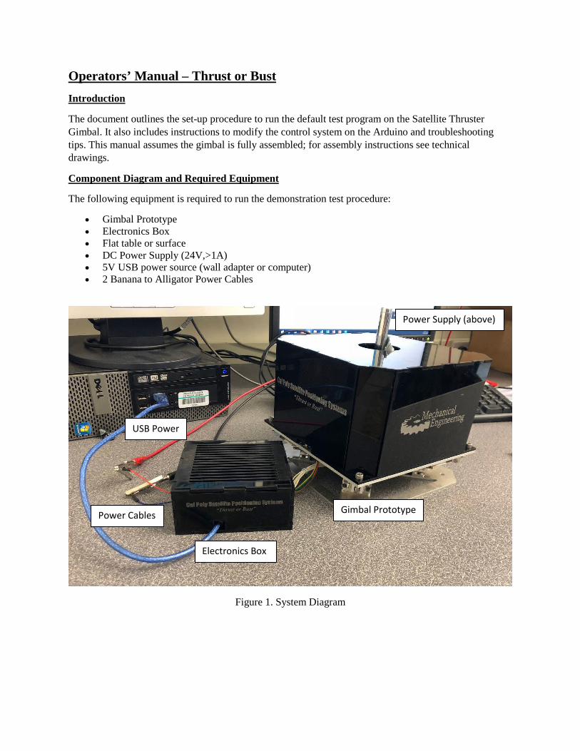
Operators’ Manual – Thrust or Bust Introduction
The document outlines the set-up procedure to run the default test program on the Satellite Thruster Gimbal. It also includes instructions to modify the control system on the Arduino and troubleshooting tips. This manual assumes the gimbal is fully assembled; for assembly instructions see technical drawings.
Component Diagram and Required Equipment
The following equipment is required to run the demonstration test procedure:
• Gimbal Prototype • Electronics Box • Flat table or surface • DC Power Supply (24V,>1A) • 5V USB power source (wall adapter or computer) • 2 Banana to Alligator Power Cables
Figure 1. System Diagram
Gimbal Prototype
Electronics Box
Power Cables
USB Power
Power Supply (above)

Test Cycle Instructions
The following instruction describe how to run the default demonstration mode. Once it is correctly set-up, it will run continuously without input from the user.
Step 1: Place gimbal baseplate on flat level surface. Secure the gimbal to the surface with bolts or a clamp.
Step 2: Attach banana cables to power supply with alligator clips on the opposite ends. Ensure the alligator clips do not touch at any point during operation. Plug the blue USB cable into a 5V source (computer or wall adapter).
Step 3: Set power supply to 24V DC voltage, set current limit to 1A.
Step 4: Open the electronics box and press the red restart button on the Arduino board. This will run the firmware loaded onto this microprocessor. This will cycle through each of the positions for 5 seconds each. Keep hands away from the gimbal to avoid pinch points, hot surfaces, and live wires.
Step 5: After the test is completed, turn off the power supply and disconnect the power supply cables.
Warnings:
Solenoids may become hot. Avoid touching solenoids during operation. Do not exceed 10W power for greater than 5 minutes.
Avoid pinch points. Keep hands away from mechanism during operation.
Harmless but painful shocks are possible. Keep hands away from alligator clips and electronics box during operation.
Test Modifications
The gimbal comes preprogrammed with a test routine. This program can be modified through the C-program in the Arduino IDE. To modify the program, download the code file, plug the blue USB cable into a computer, modify the code as required, and re-upload to the Arduino. The source code can be downloaded at the following link:
https://drive.google.com/open?id=1onqjaCb00ICId-91O-oUSQstvOKdRYiy
The example code bellow causes one actuation. The actuation occurs in three phases. First the solenoid is given full power for a short period of time to initiate motion. Then the solenoid is held at a lower power for the required time period. Finally, the solenoid is turned off and the system is allowed some time to re-

center. The power is controlled by a PWM signal. To set the duty cycle (percent of full power) adjust the power level from 0 (0%) to 255 (100%). To change the timing adjust each delay value in milliseconds.
Troubleshooting
If the gimbal is not actuating the first step is to reset the program. Open the electronics box and hit the red button located on the Arduino. Next, confirm it is correctly receiving power. Check that the ground and power line are connected to the black and red wire and that the alligator leads are not shorted together. Next, verify the LEDs on the Arduino are on. Finally open the electronics box and ensure the blue and red wires are connected to the breadboard.
If a single or multiple solenoid no longer actuates it may be because of a loose connection. The circuit is contained on a breadboard so may be prone to disconnection. To fix this problem open the electronics box and identify the loose wire. Then reattach the wire in the appropriate location based on the photo in Figure 2 or the circuit diagram in Figure 3.
Figure 2. Breadboard circuit

Figure 3. Electrical Schematic

Appendix N: Gantt Chart