Embed Size (px)
Citation preview
CAFE LAB
Voltaire Advanced Data Security, Ltd.2in1 PC™
Final Evaluation ReportVersion 1.5
Robert J. WestNicholas Pantiuk
Eric J. Grimes
June 7, 1999
COACT, Inc. Rivers Ninety-Five9140 Guilford Road, Suite LColumbia, Maryland 21046Phone: 301-498-0150Fax: 301-498-0855
Registration No. TTAP-CC-0004Document No. CA-0299-011
ii
TABLE OF CONTENTS
1 PRODUCT OVERVIEW............................................................................................................ 1
2 IDENTIFICATION .....................................................................................................................42.1 TITLE .....................................................................................................................................42.2 PRODUCT VERSION NUMBER............................................................................................42.3 VERSION NUMBERS FOR PRODUCT CONTENTS.............................................................42.4 EVALUATION ASSURANCE LEVEL (EAL) .......................................................................42.5 CONFORMANCE CLAIM......................................................................................................42.6 REGISTRATION.....................................................................................................................52.7 KEYWORDS...........................................................................................................................5
3 SECURITY POLICY ..................................................................................................................63.1 PARTITIONING ACCESS POLICY .......................................................................................63.1.1 Exceptions to the Partitioning Access Policy .........................................................................83.2 ADMINISTRATOR ACCESS POLICY...................................................................................83.3 IDENTIFICATION AND AUTHENTICATION POLICY........................................................93.4 FLOPPY DISK SWITCHING POLICY ...................................................................................9
4 ASSUMPTIONS AND CLARIFICATION OF SCOPE .............................................................104.1 ORGANISATIONAL SECURITY POLICY ASSUMPTIONS ...............................................104.2 ENVIRONMENTAL ASSUMPTIONS ..................................................................................114.3 CLARIFICATION OF SCOPE ..............................................................................................114.4 TARGET OF EVALUATION................................................................................................124.5 CLARIFICATION OF TERMINOLOGY...............................................................................12
5 ARCHITECTURE.....................................................................................................................145.1 SYSTEM OVERVIEW..........................................................................................................145.2 HARDWARE OVERVIEW ...................................................................................................155.3 SOFTWARE OVERVIEW.....................................................................................................16
6 DOCUMENTATION ................................................................................................................176.1 USER GUIDANCE................................................................................................................176.2 ADMINISTRATOR GUIDANCE..........................................................................................176.2.1 Security-Relevant Events ....................................................................................................186.3 VENDOR DOCUMENTS PROVIDED IN SUPPORT OF EVALUATION............................19
7 PRODUCT TESTING ...............................................................................................................217.1 REPLICATED VENDOR TESTING .....................................................................................227.1.1 Details of the Test Suite ......................................................................................................227.1.2 Test Configuration..............................................................................................................237.1.3 Coverage and Depth Analysis .............................................................................................247.1.4 Testing Approach ...............................................................................................................257.1.5 Results of Vendor Testing...................................................................................................257.2 EVALUATOR TESTING ......................................................................................................257.2.1 Details of the Test Suite ......................................................................................................267.2.2 Test Configuration..............................................................................................................277.2.3 Coverage and Depth Analysis .............................................................................................287.2.4 Testing Approach ...............................................................................................................297.2.5 Results of Vendor Testing...................................................................................................29
iii
TABLE OF CONTENTS – CONTINUED8 EVALUATED CONFIGURATION...........................................................................................318.1 EVALUATED HARDWARE AND SOFTWARE COMPONENTS .......................................318.1.1 Evaluated Hardware Components........................................................................................318.1.2 Evaluated Software Components.........................................................................................348.2 CONFIGURATION AND USAGE NOTES...........................................................................358.2.1 Required and Allowed Configuration Settings .....................................................................358.2.2 Evaluated Configuration Settings ........................................................................................388.2.3 Non-Evaluated Configuration Settings ................................................................................388.2.4 Incorrect Installation of the Evaluated Configuration ...........................................................398.3 TARGET ENVIRONMENT ..................................................................................................398.4 RESIDUAL VULNERABILITIES.........................................................................................39
9 RESULTS OF EVALUATION..................................................................................................419.1 SECURITY FUNCTIONAL REQUIREMENTS ....................................................................419.1.1 FDP_ACC.1 Subset Access Control ....................................................................................419.1.1.1 FDP_ACC.1.1 – Partitioning Access Policy .....................................................................419.1.1.2 FDP_ACC.1.1 – Administrator Access Policy..................................................................429.1.1.3 Dependencies ..................................................................................................................429.1.1.3.1 FDP_ACF.1 – Security attribute based access control ...................................................429.1.2 FDP_ACF.1 – Security Attribute Based Access Control ......................................................429.1.2.1 Partitioning Access Policy ...............................................................................................439.1.2.1.1 FDP_ACF.1.1 – Partitioning Access Policy ..................................................................439.1.2.1.2 FDP_ACF.1.2 – Partitioning Access Policy ..................................................................439.1.2.1.3 FDP_ACF.1.3 – Partitioning Access Policy ..................................................................449.1.2.1.4 FDP_ACF.1.4 – Partitioning Access Policy ..................................................................449.1.2.2 Administrator Access Policy............................................................................................449.1.2.2.1 FDP_ACF.1.1 – Administrator Access Policy...............................................................459.1.2.2.2 FDP_ACF.1.2 – Administrator Access Policy...............................................................459.1.2.2.3 FDP_ACF.1.3 – Administrator Access Policy...............................................................459.1.2.2.4 FDP_ACF.1.4 – Administrator Access Policy...............................................................459.1.2.3 Dependencies ..................................................................................................................459.1.2.3.1 FDP_ACC.1 – Subset access control ............................................................................459.1.2.3.2 FMT_MSA.3 – Static attribute initialisation .................................................................469.1.3 FDP_ITC.1 Import of User Data Without Security Attributes.............................................469.1.3.1 FDP_ITC.1.1...................................................................................................................469.1.3.2 FDP_ITC.1.2...................................................................................................................469.1.3.3 FDP_ITC.1.3...................................................................................................................469.1.3.4 Dependencies ..................................................................................................................479.1.3.4.1 FDP_ACC.1 Subset access control ...............................................................................479.1.3.4.2 FMT_MSA.3 Static attribute initialisation ....................................................................479.1.4 FIA_UID.2 – User Identification Before Any Action...........................................................479.1.4.1 FIA_UID.2.1...................................................................................................................479.1.4.2 Dependencies ..................................................................................................................479.1.5 FMT_MSA.1 – Management of Security Attributes.............................................................479.1.5.1 FMT_MSA.1.1................................................................................................................489.1.5.2 Dependencies ..................................................................................................................509.1.5.2.1 FDP_ACC.1 – Subset Access Control ..........................................................................509.1.5.2.2 FMT_SMR.1 – Security Roles .....................................................................................509.1.6 FMT_MSA.3 – Static Attribute Initialisation.......................................................................509.1.6.1 FMT_MSA.3.1................................................................................................................509.1.6.1.1 FMT_MSA.3.1 – Transition State ................................................................................519.1.6.1.2 FMT_MSA.3.1 – States A and B..................................................................................51
iv
TABLE OF CONTENTS – CONTINUED9.1.6.2 FMT_MSA.3.2................................................................................................................519.1.6.3 Dependencies ..................................................................................................................529.1.6.3.1 FMT_MSA.1 – Management of security attributes........................................................529.1.6.3.2 FMT_SMR.1 – Security roles.......................................................................................529.1.7 FMT_SMR.1 – Security Roles ............................................................................................529.1.7.1 FMT_SMR.1.1................................................................................................................529.1.7.2 FMT_SMR.1.2................................................................................................................529.1.7.3 Dependencies ..................................................................................................................529.1.7.3.1 FIA_UID.1 – Timing of Identification..........................................................................529.1.8 FMT_SMR.3 – Assuming Roles..........................................................................................539.1.8.1 FMT_SMR.3.1................................................................................................................539.1.8.2 Dependencies ..................................................................................................................539.1.8.2.1 FMT_SMR.1 – Security roles.......................................................................................539.1.9 FPT_FLS.1 – Fail Secure ..................................................................................................539.1.9.1 FPT_FLS.1.1...................................................................................................................539.1.9.2 Dependencies ..................................................................................................................549.1.9.2.1 ADV_SPM.1 – Informal TOE security policy model........................................................549.1.10 FPT_RCV.4 – Function Recovery .......................................................................................549.1.10.1 FPT_RCV.4.1 .................................................................................................................549.1.10.2 Dependencies ..................................................................................................................549.1.10.2.1 ADV_SPM.1 – Informal TOE security policy model ....................................................549.1.11 FPT_RVM.1 – Non-Bypassability of the TSP .....................................................................549.1.11.1 FPT_RVM.1.1 ................................................................................................................549.1.11.2 Dependencies ..................................................................................................................549.1.12 FPT_SEP.3 – Complete Reference Monitor.........................................................................559.1.12.1 FPT_SEP.3.1...................................................................................................................559.1.12.2 FPT_SEP.3.2...................................................................................................................559.1.12.3 FPT_SEP.3.3...................................................................................................................569.1.12.4 Dependencies ..................................................................................................................569.2 ASSURANCE REQUIREMENTS .........................................................................................569.2.1 ACM_CAP.2 – Configuration Items....................................................................................579.2.1.1 Evidence Elements ..................................................................................................579.2.1.2 Evaluator Action Elements and Findings..........................................................................579.2.1.2.1 Unique Version Numbers.............................................................................................579.2.1.2.2 Labeled With Reference...............................................................................................579.2.1.2.3 Configuration List........................................................................................................579.2.1.2.4 Description of Configuration Items that Comprise the TOE ..........................................609.2.1.2.5 Method of Unique Identification of Configuration Items...............................................649.2.1.2.6 Unique Identification of Configuration Items................................................................659.2.1.2.7 Configuration Items Evidence ......................................................................................669.2.2 ADO_DEL.1 – Delivery Procedures....................................................................................669.2.2.1 Evidence Elements ..................................................................................................669.2.2.2 Evaluator Action Elements and Findings..........................................................................669.2.2.2.1 Description of Delivery Procedures ..............................................................................669.2.2.2.2 Delivery Procedures Evidence......................................................................................679.2.3 ADO_IGS.1 – Installation, Generation, And Start-Up Procedures ........................................679.2.3.1 Evidence Elements ..................................................................................................679.2.3.2 Evaluator Action Elements and Findings..........................................................................679.2.3.2.1 Description of Installation, Generation, and Start-Up ....................................................679.2.3.2.2 Determination of Resulting Configuration ....................................................................689.2.3.2.3 Installation, Generation, and Start-Up Evidence............................................................68

v
TABLE OF CONTENTS – CONTINUED9.2.4 ADV_FSP.1 – Informal Functional Specification ................................................................689.2.4.1 Documentation Included in the Functional Specification ..................................................689.2.4.2 Evidence Elements ..................................................................................................689.2.4.3 Evaluator Action Elements and Findings..........................................................................699.2.4.3.1 Description of the TSF and External Interfaces .............................................................699.2.4.3.2 Internally Consistent ....................................................................................................699.2.4.3.3 Purposes and Uses of External Interfaces......................................................................699.2.4.3.3.1 ISA Bus....................................................................................................................709.2.4.3.3.2 IDE Bus – PC...........................................................................................................719.2.4.3.3.3 IDE Bus – Disk ........................................................................................................729.2.4.3.3.4 Network Connectors.................................................................................................729.2.4.3.3.5 Setup Pins/Plugs.......................................................................................................729.2.4.3.3.6 Jumper Pins..............................................................................................................749.2.4.3.4 Complete Representation of the TSF ............................................................................759.2.4.3.5 Accurate and Complete Instantiation of TOE Security Functional Requirements ...........769.2.4.6 Functional Specification Evidence ...................................................................................779.2.5 ADV_HLD.1 – Descriptive High-Level Design...................................................................779.2.5.1 Evidence Elements ..................................................................................................779.2.5.2 Documentation Included in the High-Level Design ..........................................................779.2.5.3 Evaluator Action Elements and Findings..........................................................................779.2.5.3.1 Informal High-Level Design ........................................................................................789.2.5.3.2 Internal Consistency ..................................................................................................789.2.5.3.3 Structure of the TSF in Terms of Subsystems ...............................................................789.2.5.3.4 Security Functionality Provided by Each Subsystem of the TSF....................................789.2.5.3.4.1 Main Block...............................................................................................................789.2.5.3.4.2 IDE Block ...............................................................................................................799.2.5.3.4.3 EEPROM Block .......................................................................................................809.2.5.3.4.4 State Machine Block.................................................................................................829.2.5.3.5 Underlying Hardware, Firmware, and/or Software ........................................................849.2.5.3.6 Identify All Interfaces to the Subsystems ......................................................................849.2.5.3.7 Accurate and Complete Instantiation of the TOE Security Functional Requirements......859.2.5.4 High-Level Design Evidence ...........................................................................................869.2.6 ADV_RCR.1 – Informal Correspondence Demonstration ....................................................869.2.6.1 Evidence Elements ..................................................................................................869.2.6.2 Evaluator Action Elements and Findings..........................................................................869.2.6.2.1 Correspondence Demonstration....................................................................................869.2.6.3 Informal Correspondence Evidence .................................................................................889.2.7 ADV_SPM.1 – Informal TOE Security Policy Model ..........................................................889.2.7.1 Evidence Elements ..................................................................................................889.2.7.2 Evaluator Action Elements and Findings..........................................................................899.2.7.2.1 Informal TSP Model ..................................................................................................899.2.7.2.2 Description of Rules and Characteristics.......................................................................899.2.7.2.3 Consistent and Complete Model ...................................................................................899.2.7.2.4 Correspondence Between TSP Model and Functional Specification ..............................919.2.7.2.5 Informal Security Policy Model Evidence.....................................................................919.2.8 AGD_ADM.1 – Administrator Guidance ............................................................................929.2.8.1 Evidence Elements ..................................................................................................929.2.8.2 Evaluator Action Elements and Findings..........................................................................929.2.8.2.1 Describe Administrative Functions and Interfaces.........................................................929.2.8.2.2 Describe How to Administer the TOE in a Secure Manner............................................929.2.8.2.3 Warnings About Functions and Privileges that Should Be Controlled............................92
vi
TABLE OF CONTENTS – CONTINUED9.2.8.2.4 Assumptions Regarding User Behavior ........................................................................939.2.8.2.5 Security Parameters Under the Control of the Administrator .........................................939.2.8.2.6 Security-Relevant Events .............................................................................................939.2.8.2.7 Consistency of Documentation.....................................................................................949.2.8.2.8 Security Requirements for the IT Environment .............................................................959.2.9 AGD_USR.1 – User Guidance ............................................................................................959.2.9.1 Evidence Elements ..................................................................................................959.2.9.2 Evaluator Action Elements and Findings..........................................................................959.2.9.2.1 User Functions and interfaces.......................................................................................959.2.9.2.2 Use of User Functions..................................................................................................959.2.9.2.3 Warnings About User Functions and Privileges ............................................................969.2.9.2.4 User Responsibilities....................................................................................................969.2.9.2.5 Consistency with Other Documentation .......................................................................969.2.9.2.6 User Relevant Environmental Security Requirements ...................................................979.2.10 ATE_COV.1 – Evidence of Coverage .................................................................................979.2.10.1 Evidence Elements ..................................................................................................979.2.10.2 Evaluator Action Elements and Findings..........................................................................979.2.10.2.1 Correspondence Between Tests and Functional Specification........................................979.2.10.2.2 Test Coverage Evidence...............................................................................................999.2.11 ATE_FUN.1 – Functional Testing.......................................................................................999.2.11.1 Evidence Elements ..................................................................................................999.2.11.2 Evaluator Action Elements and Findings..........................................................................999.2.11.2.1 Content of Test Documentation ....................................................................................999.2.11.2.2 Developer Test Documentation Examination ..............................................................1009.2.11.2.3 Test Documentation Examination Results...................................................................1009.2.12 ATE_IND.2 – Independent Testing – Sample....................................................................1029.2.12.1 Evidence Elements ................................................................................................1029.2.12.2 Evaluator Action Elements and Findings........................................................................1039.2.12.2.1 TOE Suitable for Testing ...........................................................................................1039.2.12.2.2 Equivalent Set of Resources .......................................................................................1039.2.12.2.3 Test a Subset of the TSF.............................................................................................1059.2.12.2.4 Verify Test Results for a Sample of Tests ...................................................................1069.2.13 AVA_SOF.1 – Strength of TOE Security Function Evaluation ..........................................1089.2.13.1 Evidence Elements ................................................................................................1089.2.13.2 Evaluator Action Elements and Findings........................................................................1089.2.13.2.1 Minimum Strength Level ...........................................................................................1089.2.13.2.2 Meets or Exceeds Claimed Strength of Function Metric..............................................1089.2.13.2.3 Confirm Correctness of Claimed Strength of Function ................................................1089.2.14 AVA_VLA.1 – Developer Vulnerability Analysis .............................................................1089.2.14.1 Evidence Elements ................................................................................................1089.2.14.2 Evaluator Action Elements and Findings........................................................................1089.2.14.2.1 Content of Developer’s Vulnerability Analysis ...........................................................1089.2.14.2.2 Security Threats Addressed by the TOE .....................................................................1099.2.14.2.3 Security Threats Addressed by the Operating Environment.........................................1099.2.14.2.4 Obvious and Residual Vulnerabilities .........................................................................1099.2.14.2.5 Exploitability of Obvious Vulnerabilities....................................................................1109.2.14.2.6 Consistency of Documentation...................................................................................1109.2.14.2.7 CAFÉ Lab Vulnerability Testing................................................................................1119.2.14.2.7.1 Obvious Vulnerabilities ..........................................................................................1129.2.14.2.7.2 Residual Vulnerabilities..........................................................................................113

vii
TABLE OF CONTENTS – CONTINUED10 EVALUATOR COMMENTS/RECOMMENDATIONS ..........................................................11410.1 PRODUCT ENVIRONMENT..............................................................................................11410.2 INDIVIDUAL IDENTIFICATION & AUTHENTICATION................................................11410.3 USE OF THE CEM .............................................................................................................114
TABLES
Table 1-1 Security Functional Requirements ....................................................................2Table 1-2 Assurance Requirements ..................................................................................2Table 3.1-1 Transition State Access Rules ...........................................................................7Table 3.1-2 State A Access Rules........................................................................................7Table 3.1-3 State B Access Rules ........................................................................................8Table 3.4-1 Floppy Disk Switching Policy Rules .................................................................9Table 7.1.2-1 Partition Configuration...................................................................................23Table 7.1.2-2 Settings Configuration....................................................................................24Table 7.1.3-1 Developer Tests Correspondence to Functional Specifications ........................24Table 7.2.2-1 Partition Configuration...................................................................................27Table 7.2.2-2 Settings Configuration....................................................................................28Table 7.2.3-1 Independent Tests Correspondence to Functional Specifications......................28Table 7.2.5-1 Overall Test Correspondence to Functional Specifications ..............................29Table 8.1.1-1 Evaluated 2in1 PC™ Card List .......................................................................32Table 8.1.1-2 Evaluated Elements Complementing the 2in1 PC™ Card................................34Table 8.2.1-1 Allowed Configuration Settings......................................................................35Table 9.1-1 Security Functional Requirements ..................................................................41Table 9.1.2.1.2-1 Partitioning Access Policy Rules.....................................................................44Table 9.1.5.1-1 Administrator Dependant Attributes and Parameters .......................................48Table 9.1.6.1-1 Administrator Selectable Security Attributes...................................................51Table 9.2-1 Assurance Requirements ................................................................................56Table 9.2.1.2.3-1 Container Items..............................................................................................58Table 9.2.1.2.3-2 Software Elements Disk 1...............................................................................58Table 9.2.1.2.3-3 Software Elements Disk 2...............................................................................59Table 9.2.1.2.3-4 Card Components...........................................................................................60Table 9.2.1.2.4-1 Container Items..............................................................................................60Table 9.2.1.2.4-2 Software Elements Disk 1...............................................................................61Table 9.2.1.2.4-3 Software Elements Disk 2...............................................................................63Table 9.2.1.2.4-4 Card Components...........................................................................................63Table 9.2.1.2.4-1 Container Items..............................................................................................64Table 9.2.1.2.5-2 Card Components...........................................................................................65Table 9.2.4.3.3-1 Uses of the IDE Interface................................................................................71Table 9.2.4.3.3-2 Setup Pins/Plug Uses ......................................................................................73Table 9.2.4.3.3-3 2in1 PC™ Jumper Pins...................................................................................74Table 9.2.4.3.5-1 Security Functional Requirements to Functional Specification Mapping..........76Table 9.2.5.3.4-1 Administrator Dependant Attributes and Parameters .......................................80Table 9.2.5.3.6-1 Interfaces to the Blocks ..................................................................................84Table 9.2.5.3.7-1 Mapping of Functional Specification to High-Level Design ...........................85Table 9.2.5.3.7-2 Mapping of High-Level Design to Functional Specification ............................86
viii
TABLES – CONTINUEDTable 9.2.6.2.1-1 Functions to Security Functional Requirements Mapping ................................87Table 9.2.6.2.1-2 Security Functional Requirements to Functional Specification Mapping..........87Table 9.2.6.2.1-3 Mapping of Functional Specification to High-Level Design ...........................88Table 9.2.6.2.1-4 Mapping of High-Level Design to Functional Specification ............................88Table 9.2.7.2.3-1 Mode/Role Use By Policies ............................................................................90Table 9.2.7.2.3-2 Partitioning Access Policy Rules.....................................................................90Table 9.2.7.2.3-3 Partitioning Access Policy Exception Rules ....................................................90Table 9.2.7.2.4-1 Security Policy Model to Functional Specification Mapping............................91Table 9.2.10.2.1-1 Correspondence of Developer and Independent Tests to Functional
Specifications.................................................................................................97Table 9.2.10.2.1-2 Identification of Developer Tests ....................................................................98Table 9.2.10.2.1-3 Identification of Independent Tests .................................................................98Table 9.2.11.2.1-1 Vendor Test Documentation .........................................................................100Table 9.2.11.2.2-1 ATE_FUN.1.1C – Test Documentation Examination ....................................100Table 9.2.11.2.2-2 Developer Tests............................................................................................101Table 9.2.11.2.2-3 Independent Tests.........................................................................................102Table 9.2.14.2.4-1 Obvious Vulnerabilities ................................................................................109Table 9.2.14.2.4-2 Residual Vulnerabilities................................................................................109Table 9.2.14.2.6-1 Vulnerability Mapping .................................................................................111Table 9.2.14.2.7-1 Sample Tests to Confirm Developer Vulnerability Test Results .....................112Table 9.2.14.2.7-1 TSF Tests to Confirm Mitigation of TOE Vulnerabilities ..............................112Table 9.2.14.2.7.1-1 Obvious Vulnerabilities ................................................................................112Table 9.2.14.2.7.2-2 Residual Vulnerabilities................................................................................113
APPENDICES
A ACRONYMS ...................................................................................................................A-1B Evaluation Test Plan for the 2in1 PC™ , Version 1.21 .......................................................B-1C BIBLIOGRAPHY ............................................................................................................C-1

1
SECTION 1
EXECUTIVE SUMMARY
1 PRODUCT OVERVIEW
The Target of Evaluation (TOE) is the 2in1 PC™ card, the supporting software providedon the installation floppy diskettes, and the documentation provided as part of the 2in1PC™ product developed by Voltaire that provides physical separation between twonetworks through the use of a hardware based security controller that is embedded on the2in1 PC™ card. The 2in1 PC™ card is installed on a single host PC that conforms to thePC/AT standard and is configured by using the supplied installation diskettes. Thesediskettes partition the host PC’s hard disk into three or four separate disk partitions andallow for the configuration of the security functions on 2in1 PC™ card itself. Once the2in1 PC™ card has been configured, the security controller manages both the PC’sconnection between two networks and the access to the PC’s configured disk partitions.This enables a single PC to securely connect to two physically separated networkconnections, while protecting the data stored on the PC’s hard disk(s). Security isachieved by a state machine that allows the PC to access only the network connection anddisk partition(s) associated with that machine state.
The 2in1 PC™ installation disks partition a PC into two distinct user domains (A and B).Each of the domains consists of a portion of the hard disk, a network connection, and,optionally, some other devices (e.g., floppy disk, SCSI interface, etc.). It also provides acapability for an administrator to set-up and configure the controls necessary toimplement these functions.
The TOE recognises two types of users (roles), users and administrators, and two modesof operation, work mode and set-up mode. In work mode, there are three user machinestates; A, B, and Transition (T), and four user visible functions that the TSF controls.They are:
1. Read or write access to disk partitions,
2. Connectivity to networks,
3. Connectivity to other (optional) TSF controlled devices, and
4. Switch user states.
In set-up mode, only the administrator function is recognised and permits theInitialisation or modification of parameters and configuration information. In this mode,I/O operations to the hard disk are not monitored and both network connections aresevered. The administrator role is determined through the installation of an internal set-up
2
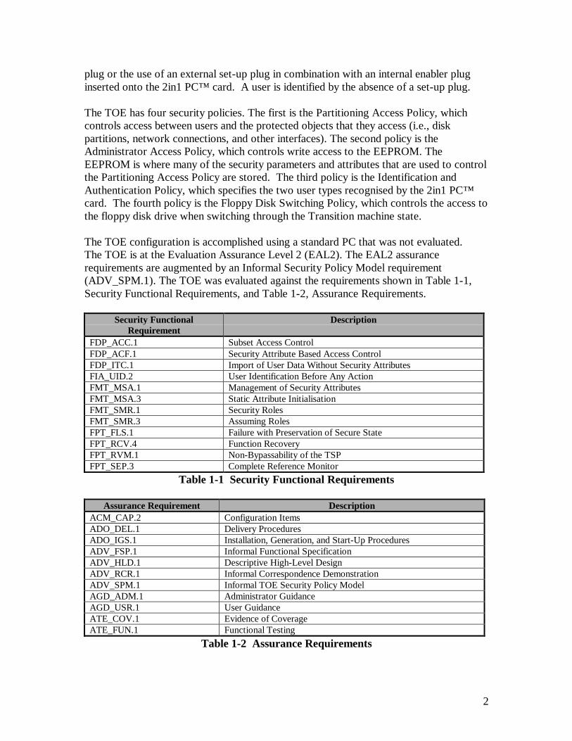
plug or the use of an external set-up plug in combination with an internal enabler pluginserted onto the 2in1 PC™ card. A user is identified by the absence of a set-up plug.
The TOE has four security policies. The first is the Partitioning Access Policy, whichcontrols access between users and the protected objects that they access (i.e., diskpartitions, network connections, and other interfaces). The second policy is theAdministrator Access Policy, which controls write access to the EEPROM. TheEEPROM is where many of the security parameters and attributes that are used to controlthe Partitioning Access Policy are stored. The third policy is the Identification andAuthentication Policy, which specifies the two user types recognised by the 2in1 PC™card. The fourth policy is the Floppy Disk Switching Policy, which controls the access tothe floppy disk drive when switching through the Transition machine state.
The TOE configuration is accomplished using a standard PC that was not evaluated.The TOE is at the Evaluation Assurance Level 2 (EAL2). The EAL2 assurancerequirements are augmented by an Informal Security Policy Model requirement(ADV_SPM.1). The TOE was evaluated against the requirements shown in Table 1-1,Security Functional Requirements, and Table 1-2, Assurance Requirements.
Security FunctionalRequirement
Description
FDP_ACC.1 Subset Access ControlFDP_ACF.1 Security Attribute Based Access ControlFDP_ITC.1 Import of User Data Without Security AttributesFIA_UID.2 User Identification Before Any ActionFMT_MSA.1 Management of Security AttributesFMT_MSA.3 Static Attribute InitialisationFMT_SMR.1 Security RolesFMT_SMR.3 Assuming RolesFPT_FLS.1 Failure with Preservation of Secure StateFPT_RCV.4 Function RecoveryFPT_RVM.1 Non-Bypassability of the TSPFPT_SEP.3 Complete Reference Monitor
Table 1-1 Security Functional Requirements
Assurance Requirement DescriptionACM_CAP.2 Configuration ItemsADO_DEL.1 Delivery ProceduresADO_IGS.1 Installation, Generation, and Start-Up ProceduresADV_FSP.1 Informal Functional SpecificationADV_HLD.1 Descriptive High-Level DesignADV_RCR.1 Informal Correspondence DemonstrationADV_SPM.1 Informal TOE Security Policy ModelAGD_ADM.1 Administrator GuidanceAGD_USR.1 User GuidanceATE_COV.1 Evidence of CoverageATE_FUN.1 Functional Testing
Table 1-2 Assurance Requirements
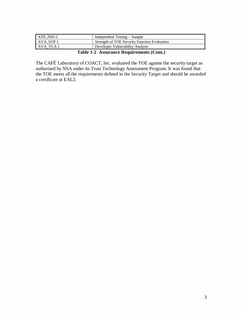
3
ATE_IND.2 Independent Testing – SampleAVA_SOF.1 Strength of TOE Security Function EvaluationAVA_VLA.1 Developer Vulnerability Analysis
Table 1-2 Assurance Requirements (Cont.)
The CAFÉ Laboratory of COACT, Inc. evaluated the TOE against the security target asauthorised by NSA under its Trust Technology Assessment Program. It was found thatthe TOE meets all the requirements defined in the Security Target and should be awardeda certificate at EAL2.
4
SECTION 2
IDENTIFICATION
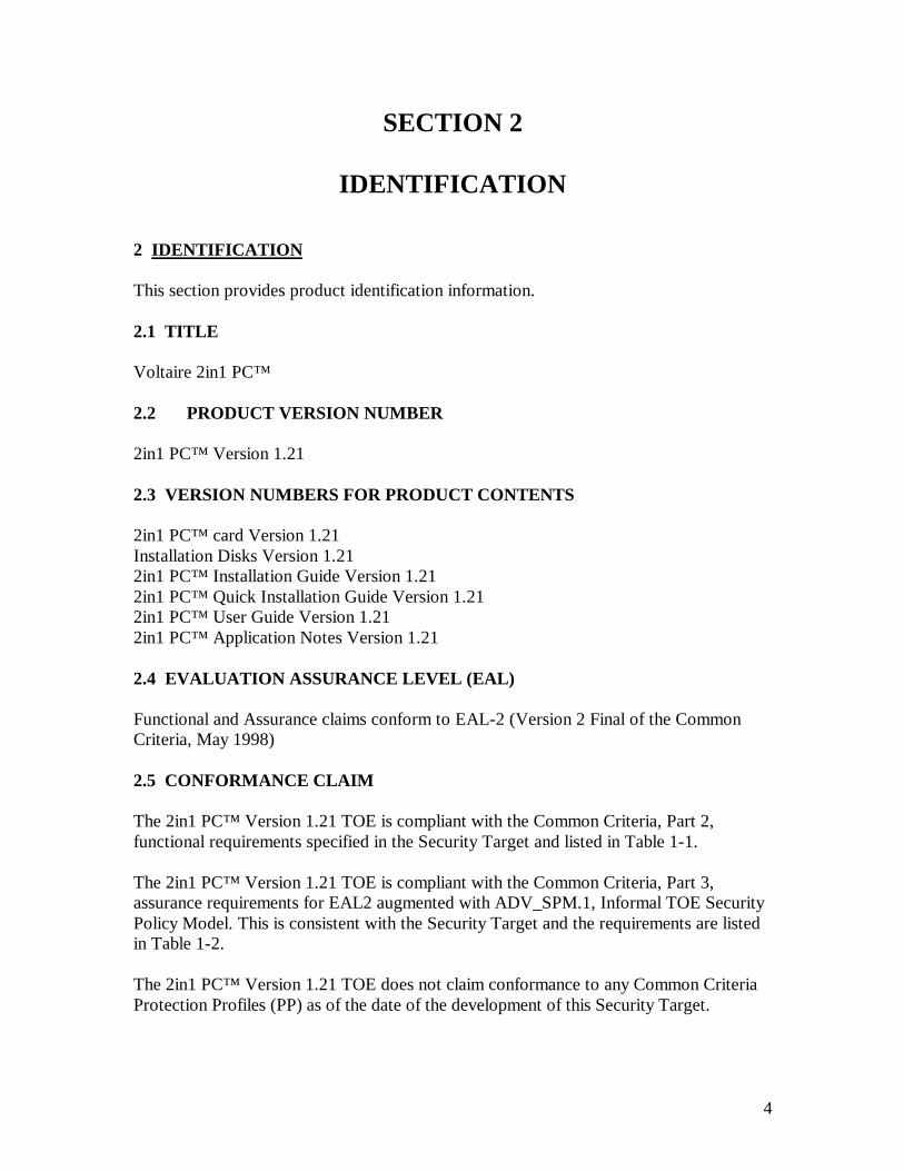
2 IDENTIFICATION
This section provides product identification information.
2.1 TITLE
Voltaire 2in1 PC™
2.2 PRODUCT VERSION NUMBER
2in1 PC™ Version 1.21
2.3 VERSION NUMBERS FOR PRODUCT CONTENTS
2in1 PC™ card Version 1.21Installation Disks Version 1.212in1 PC™ Installation Guide Version 1.212in1 PC™ Quick Installation Guide Version 1.212in1 PC™ User Guide Version 1.212in1 PC™ Application Notes Version 1.21
2.4 EVALUATION ASSURANCE LEVEL (EAL)
Functional and Assurance claims conform to EAL-2 (Version 2 Final of the CommonCriteria, May 1998)
2.5 CONFORMANCE CLAIM
The 2in1 PC™ Version 1.21 TOE is compliant with the Common Criteria, Part 2,functional requirements specified in the Security Target and listed in Table 1-1.
The 2in1 PC™ Version 1.21 TOE is compliant with the Common Criteria, Part 3,assurance requirements for EAL2 augmented with ADV_SPM.1, Informal TOE SecurityPolicy Model. This is consistent with the Security Target and the requirements are listedin Table 1-2.
The 2in1 PC™ Version 1.21 TOE does not claim conformance to any Common CriteriaProtection Profiles (PP) as of the date of the development of this Security Target.

5
2.6 REGISTRATION
Registration No. TTAP-CC-0004
2.7 KEYWORDS
Multi-level security, COTS, access control, discretionary control, network security,network security hardware, networked information systems, data security, andinformation protection.
6
SECTION 3
SECURITY POLICY
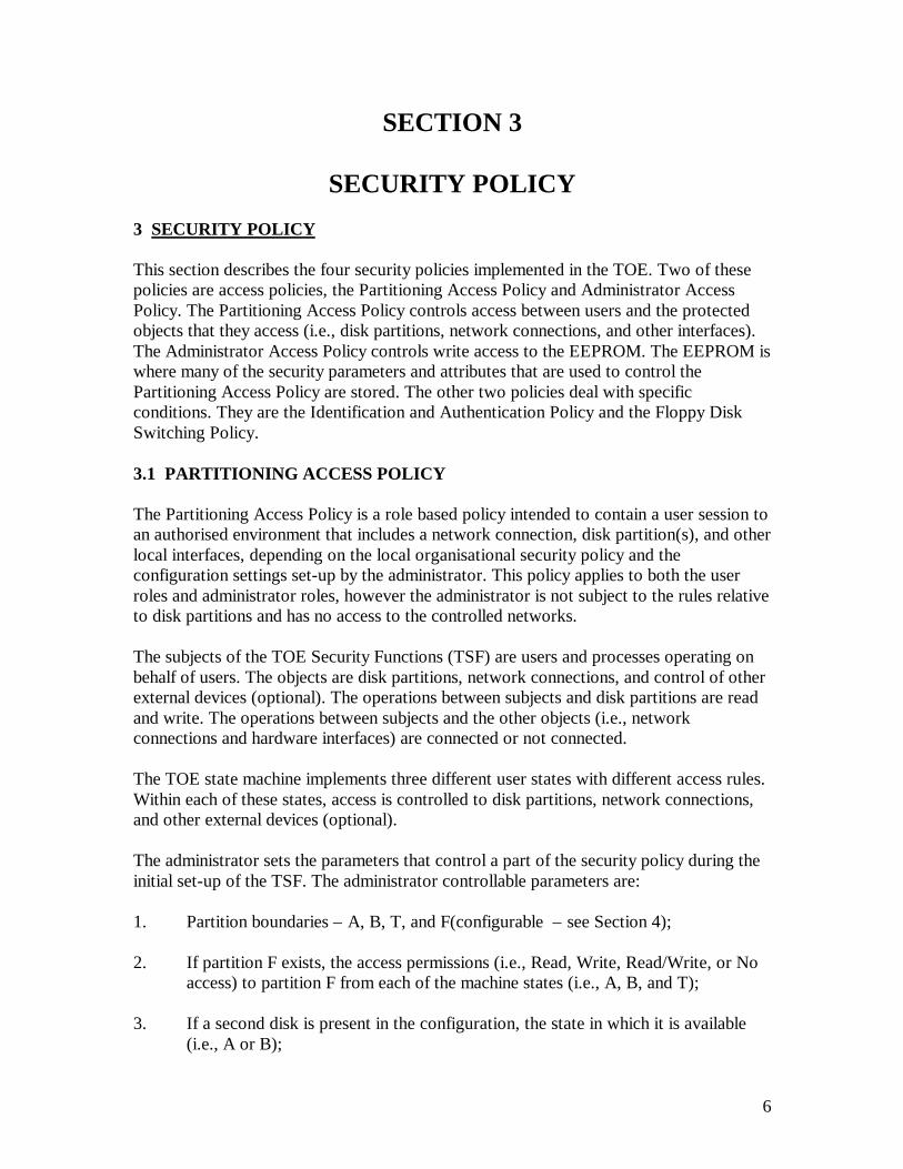
3 SECURITY POLICY
This section describes the four security policies implemented in the TOE. Two of thesepolicies are access policies, the Partitioning Access Policy and Administrator AccessPolicy. The Partitioning Access Policy controls access between users and the protectedobjects that they access (i.e., disk partitions, network connections, and other interfaces).The Administrator Access Policy controls write access to the EEPROM. The EEPROM iswhere many of the security parameters and attributes that are used to control thePartitioning Access Policy are stored. The other two policies deal with specificconditions. They are the Identification and Authentication Policy and the Floppy DiskSwitching Policy.
3.1 PARTITIONING ACCESS POLICY
The Partitioning Access Policy is a role based policy intended to contain a user session toan authorised environment that includes a network connection, disk partition(s), and otherlocal interfaces, depending on the local organisational security policy and theconfiguration settings set-up by the administrator. This policy applies to both the userroles and administrator roles, however the administrator is not subject to the rules relativeto disk partitions and has no access to the controlled networks.
The subjects of the TOE Security Functions (TSF) are users and processes operating onbehalf of users. The objects are disk partitions, network connections, and control of otherexternal devices (optional). The operations between subjects and disk partitions are readand write. The operations between subjects and the other objects (i.e., networkconnections and hardware interfaces) are connected or not connected.
The TOE state machine implements three different user states with different access rules.Within each of these states, access is controlled to disk partitions, network connections,and other external devices (optional).
The administrator sets the parameters that control a part of the security policy during theinitial set-up of the TSF. The administrator controllable parameters are:
1. Partition boundaries – A, B, T, and F(configurable – see Section 4);
2. If partition F exists, the access permissions (i.e., Read, Write, Read/Write, or Noaccess) to partition F from each of the machine states (i.e., A, B, and T);
3. If a second disk is present in the configuration, the state in which it is available(i.e., A or B);
7
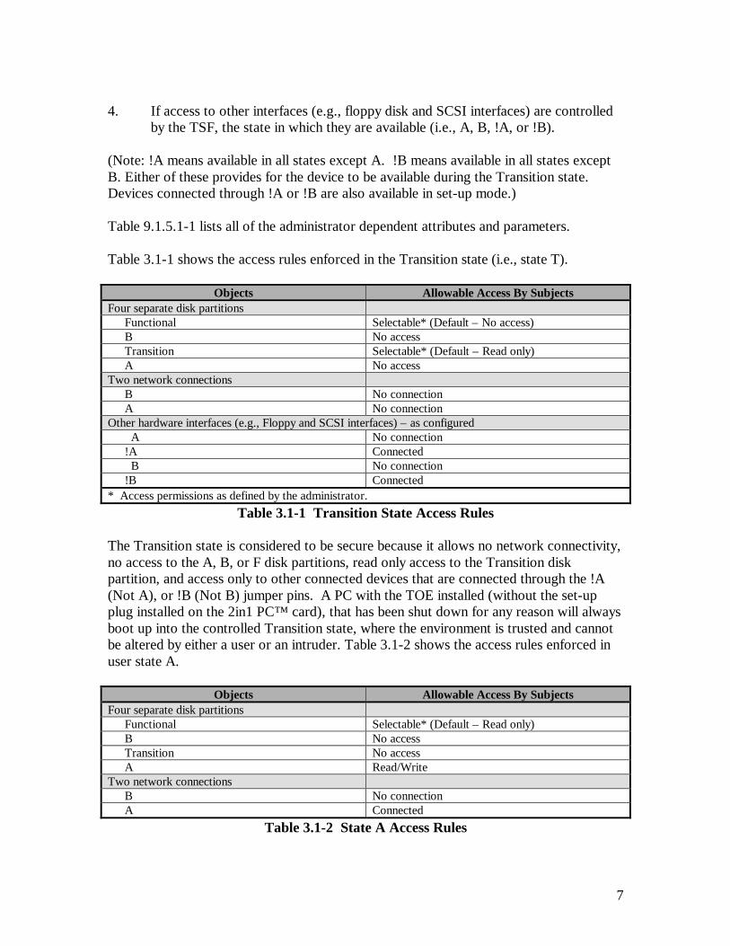
4. If access to other interfaces (e.g., floppy disk and SCSI interfaces) are controlledby the TSF, the state in which they are available (i.e., A, B, !A, or !B).
(Note: !A means available in all states except A. !B means available in all states exceptB. Either of these provides for the device to be available during the Transition state.Devices connected through !A or !B are also available in set-up mode.)
Table 9.1.5.1-1 lists all of the administrator dependent attributes and parameters.
Table 3.1-1 shows the access rules enforced in the Transition state (i.e., state T).
Objects Allowable Access By SubjectsFour separate disk partitions
Functional Selectable* (Default – No access)B No accessTransition Selectable* (Default – Read only)A No access
Two network connectionsB No connectionA No connection
Other hardware interfaces (e.g., Floppy and SCSI interfaces) – as configured A No connection!A Connected B No connection!B Connected
* Access permissions as defined by the administrator.Table 3.1-1 Transition State Access Rules
The Transition state is considered to be secure because it allows no network connectivity,no access to the A, B, or F disk partitions, read only access to the Transition diskpartition, and access only to other connected devices that are connected through the !A(Not A), or !B (Not B) jumper pins. A PC with the TOE installed (without the set-upplug installed on the 2in1 PC™ card), that has been shut down for any reason will alwaysboot up into the controlled Transition state, where the environment is trusted and cannotbe altered by either a user or an intruder. Table 3.1-2 shows the access rules enforced inuser state A.
Objects Allowable Access By SubjectsFour separate disk partitions
Functional Selectable* (Default – Read only)B No accessTransition No accessA Read/Write
Two network connectionsB No connectionA Connected
Table 3.1-2 State A Access Rules

8
Objects Allowable Access By SubjectsOther hardware interfaces (e.g., Floppy and SCSI interfaces) – as configured
A Connected!A No connection B No connection!B Connected
* Access permissions as defined by the administrator.Table 3.1-2 State A Access Rules (Cont.)
Table 3.1-3 shows the access rules enforced in user state B.
Objects Allowable Access By SubjectsFour separate disk partitions
Functional Selectable* (Default – Read/Write)B Read/WriteTransition No accessA No access
Two network connectionsB ConnectedA No connection
Other hardware interfaces (e.g., Floppy and SCSI interfaces) – as configured A No connection!A Connected B Connected!B No connection
* Access permissions as defined by the administrator.Table 3.1-3 State B Access Rules
3.1.1 Exceptions to the Partitioning Access Policy
When the administrator has identified himself by inserting the set-up plug into the 2in1PC™ card the following exceptions are made to the Partitioning Access Policy:
1. Unconditional access is allowed to all disk partitions. Typically, the administratoraccesses only partitions associated with the partition he is booted from, but thataccess is not monitored or controlled by the TSF.
2. No network connections are allowed.
3. Other device connections are allowed for devices associated with !A (Not A) or!B (Not B), and disallowed for devices associated with A and B.
4. Always boot into A, boot into T is bypassed.
3.2 ADMINISTRATOR ACCESS POLICY
The Administrator Access Policy provides the rules for write access to the EEPROM,where many of the security parameters and attributes that are used to control the
9
Partitioning Access Policy are stored. Other dynamic parameters, such as the currentmachine state, are stored in the Altera chip.
The Administrator Access Policy is a role-based policy intended to limit write access tothe EEPROM to administrators. Like the Partitioning Access Policy, the subjects areusers and processes operating on behalf of users, but the only object is the EEPROM andthe only controlled operation is write. The Administrator Access Policy is very simple;administrators may write to the EEPROM, users may not.
3.3 IDENTIFICATION AND AUTHENTICATION POLICY
Another security policy covers identification and authentication. The TOE identifies onlyuser roles (i.e., user and administrator), not users as individuals. By definition, anyindividual operating without the set-up plug in place is a user. Also by definition, anyindividual operating with the set-up plug in place is an administrator.
3.4 FLOPPY DISK SWITCHING POLICY
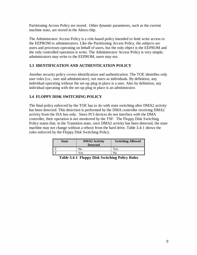
The final policy enforced by the TOE has to do with state switching after DMA2 activityhas been detected. This detection is performed by the DMA controller receiving DMA2activity from the ISA bus only. Since PCI devices do not interface with the DMAcontroller, their operation is not monitored by the TSF. The Floppy Disk SwitchingPolicy states that, in the Transition state, once DMA2 activity has been detected, the statemachine may not change without a reboot from the hard drive. Table 3.4-1 shows therules enforced by the Floppy Disk Switching Policy.
State DMA2 ActivityDetected
Switching Allowed
T No YesT Yes No
Table 3.4-1 Floppy Disk Switching Policy Rules

10
SECTION 4
ASSUMPTIONS ANDCLARIFICATION OF SCOPE
4 ASSUMPTIONS AND CLARIFICATION OF SCOPE
This section provides information about assumptions regarding organisational securitypolicy and the operating environment used in the evaluation of the TOE, clarification ofthe scope of the evaluation, and clarification of some terminology used either by thevendor or the evaluators.
4.1 ORGANISATIONAL SECURITY POLICY ASSUMPTIONS
The following organisational security policies are beyond the scope of the Target ofEvaluation (TOE) and were assumed to be implemented in the evaluation:
1. Users must be identified and authenticated before access to the TOE can begranted.Rationale: In some environments, identification and authentication mechanismsmay be required and therefore must be supplied by the operational environment,as the TOE only requires identification for administrator privileges.
2. Administrators of the system will be adequately trained, enabling them toeffectively implement organisational security policies.Rationale: Administrators are expected to use IT resources and information inaccordance with the organisational security policy. In order for this to bepossible, administrators must be adequately trained to understand the purposeand need for security controls, and to be able to make secure decisions withrespect to their discretionary actions.
3. The organisation’s IT resources must be used only for authorised purposes.Rationale: In conjunction with the TOE environment, users must ensure that theorganisation’s information technology is not used for unauthorised purposes.
4. The organisation’s IT systems must be implemented and operated in a mannerthat represents due care and diligence with respect to any risks to the organisation.Rationale: It is important that the level of security afforded the IT system be inaccordance with what is generally considered adequate within the business orgovernment sector in which the organisation is placed.

11
4.2 ENVIRONMENTAL ASSUMPTIONS
The specific conditions listed below are assumed to exist in the TOE environment.These assumptions include both practical realities in the development of the TOE securityrequirements and the essential environmental conditions on the use of the TOE.
1. The operating systems and supporting software stored in the Transition, A, and Bdisk partitions are not relied upon for security functionality.Rationale: These components are beyond the scope of the TSF.
2. Users of the TOE are trusted not to modify the hardware configuration.Rationale: Personnel security and determination of trusted users is beyond thescope of the TOE.
3. The TOE will be located in a controlled environment (i.e. basic physical securityis assumed to prevent modification of the system hardware / software).Rationale: Physical security of the host system is beyond the scope of the TOE.
4. The Personal Computer (PC) platform fully complies with the PC/AT standardand uses an IDE controller for the primary system disk.Rationale: Standard compliance of the host system is beyond the scope of theTOE.
4.3 CLARIFICATION OF SCOPE
Administrator set-up software is not a part of the TSF and is not used in work mode. Itexists on the 2in1 PC™ installation disks and should never be left available to a user. Theadministrator must use physical and procedural means to protect these disks. The firstdisk is a bootable floppy disk that will run only in set-up mode (i.e., with theadministrator set-up plug installed on the 2in1 PC™ card).
There is a “SWITCH” process present in each machine environment (i.e., machine statesA, B, and T, loaded with whatever TOE compatible operating system is loaded in theirdisk partitions). This “SWITCH” process is executed when the user initiates it, either byclicking the icon or by invoking the “SWITCH” command, depending on the operatingsystem and/or user choice. The “SWITCH” process notifies the TOE of its intent tochange user states on the next reset signal, and then causes a reset signal to be sent. Thisprocess is not part of the TSF. This process is provided for the convenience of the user,but the user could choose to provide the same functionality himself. The user interface tothe TSF, for the purpose of a state change, is the combination of the two events from theuser. If the user does not initiate the events, or initiates only one of the events, the statechange does not occur and the user is left in his present state.
The TOE must be installed on a PC/AT compatible system with an IDE controller for theprimary system drive. It does not rely on this system for any security functionality, and it

12
does not claim to provide any security functionality for any system that does not meetthese standards.
4.4 TARGET OF EVALUATION
The TOE is the 2in1 PC™ card, the supporting software provided on the installationfloppy diskettes, and the documentation provided as part of the TOE developed byVoltaire.
4.5 CLARIFICATION OF TERMINOLOGY
In this evaluation, the following terms and phrases have a specific meaning that maydiffer somewhat from common usage.
Control Access to External Devices (e.g., floppy disk and/or SCSI interface) – Accesscontrol to external devices is provided by controlling the passage of a control signal (e.g.,“device ready” for the floppy disk) on the device ribbon cable. The wire carrying thecontrol signal is physically interrupted and taken from the ribbon cable and connected tojumper pins on the 2in1 PC™ card. From the input jumper pin, the connection is routedthrough an electro-mechanical relay to the output jumper pin. Access is controlled to thedevice by allowing or not allowing the control signal through the electro-mechanicalrelay. No other command, address, or data line on the device cable is monitored by theTSF. By PC standard convention, the interface will not recognise any command, address,or data present on the device cable until the control signal is received.
Optional – The internal enabler plug, external set-up plug, and the cables provided tocontrol external devices are additional elements that were not included as part of theTOE. These additional elements were ordered from the developer and their functionalitywas evaluated to verify that the jumper pins on the 2in1 PC™ card do provide the abilityto control external devices and that the combination of the internal enabler plug and theexternal set-up plug is an equivalent to the internal set-up plug.
Detect Floppy Disk Usage – Floppy disk usage is associated and is based on the detectionof DMA2 (DRQ2) signals on the ISA bus. This detection is performed by the DMAcontroller receiving DMA2 activity from the ISA bus only. Since PCI devices do notinterface with the DMA controller, their operation is not monitored by the TSF.
Control Access to Networks – Access control to networks is provided by controlling thepassage of the network connection through two electro-mechanical relays. Both relaysmust be closed for the network connection to be made.
Secure/Public – Various developer documents refer to the user (i.e., work mode) states,as well as disk partitions, network and external device connections, as “Secure” and“Public”. These terms are merely labels the developer uses for the machine states and theprotected assets associated with them. In this context, the term “Secure” does not implythat there is any inherent security associated with it. Some of the developer
13
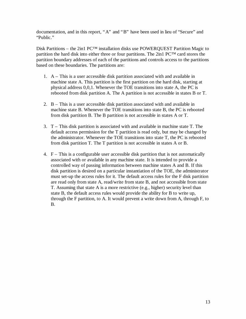
documentation, and in this report, “A” and “B” have been used in lieu of “Secure” and“Public.”
Disk Partitions – the 2in1 PC™ installation disks use POWERQUEST Partition Magic topartition the hard disk into either three or four partitions. The 2in1 PC™ card stores thepartition boundary addresses of each of the partitions and controls access to the partitionsbased on these boundaries. The partitions are:
1. A – This is a user accessible disk partition associated with and available inmachine state A. This partition is the first partition on the hard disk, starting atphysical address 0,0,1. Whenever the TOE transitions into state A, the PC isrebooted from disk partition A. The A partition is not accessible in states B or T.
2. B – This is a user accessible disk partition associated with and available inmachine state B. Whenever the TOE transitions into state B, the PC is rebootedfrom disk partition B. The B partition is not accessible in states A or T.
3. T – This disk partition is associated with and available in machine state T. Thedefault access permission for the T partition is read only, but may be changed bythe administrator. Whenever the TOE transitions into state T, the PC is rebootedfrom disk partition T. The T partition is not accessible in states A or B.
4. F – This is a configurable user accessible disk partition that is not automaticallyassociated with or available in any machine state. It is intended to provide acontrolled way of passing information between machine states A and B. If thisdisk partition is desired on a particular instantiation of the TOE, the administratormust set-up the access rules for it. The default access rules for the F disk partitionare read only from state A, read/write from state B, and not accessible from stateT. Assuming that state A is a more restrictive (e.g., higher) security level thanstate B, the default access rules would provide the ability for B to write up,through the F partition, to A. It would prevent a write down from A, through F, toB.
14
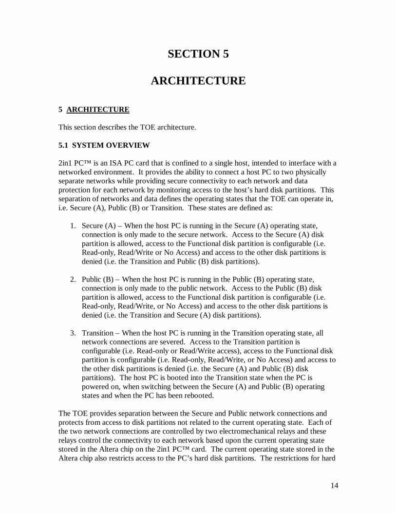
SECTION 5
ARCHITECTURE
5 ARCHITECTURE
This section describes the TOE architecture.
5.1 SYSTEM OVERVIEW
2in1 PC™ is an ISA PC card that is confined to a single host, intended to interface with anetworked environment. It provides the ability to connect a host PC to two physicallyseparate networks while providing secure connectivity to each network and dataprotection for each network by monitoring access to the host’s hard disk partitions. Thisseparation of networks and data defines the operating states that the TOE can operate in,i.e. Secure (A), Public (B) or Transition. These states are defined as:
1. Secure (A) – When the host PC is running in the Secure (A) operating state,connection is only made to the secure network. Access to the Secure (A) diskpartition is allowed, access to the Functional disk partition is configurable (i.e.Read-only, Read/Write or No Access) and access to the other disk partitions isdenied (i.e. the Transition and Public (B) disk partitions).
2. Public (B) – When the host PC is running in the Public (B) operating state,connection is only made to the public network. Access to the Public (B) diskpartition is allowed, access to the Functional disk partition is configurable (i.e.Read-only, Read/Write, or No Access) and access to the other disk partitions isdenied (i.e. the Transition and Secure (A) disk partitions).
3. Transition – When the host PC is running in the Transition operating state, allnetwork connections are severed. Access to the Transition partition isconfigurable (i.e. Read-only or Read/Write access), access to the Functional diskpartition is configurable (i.e. Read-only, Read/Write, or No Access) and access tothe other disk partitions is denied (i.e. the Secure (A) and Public (B) diskpartitions). The host PC is booted into the Transition state when the PC ispowered on, when switching between the Secure (A) and Public (B) operatingstates and when the PC has been rebooted.
The TOE provides separation between the Secure and Public network connections andprotects from access to disk partitions not related to the current operating state. Each ofthe two network connections are controlled by two electromechanical relays and theserelays control the connectivity to each network based upon the current operating statestored in the Altera chip on the 2in1 PC™ card. The current operating state stored in theAltera chip also restricts access to the PC’s hard disk partitions. The restrictions for hard
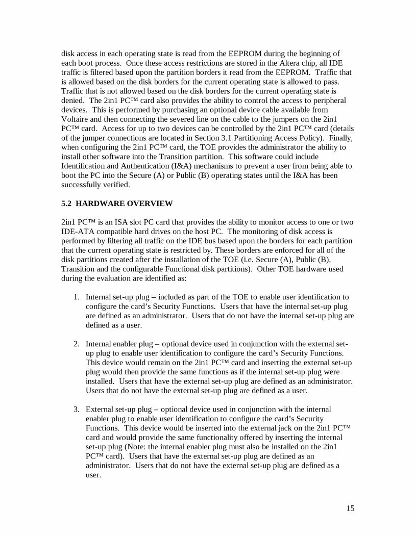
15
disk access in each operating state is read from the EEPROM during the beginning ofeach boot process. Once these access restrictions are stored in the Altera chip, all IDEtraffic is filtered based upon the partition borders it read from the EEPROM. Traffic thatis allowed based on the disk borders for the current operating state is allowed to pass.Traffic that is not allowed based on the disk borders for the current operating state isdenied. The 2in1 PC™ card also provides the ability to control the access to peripheraldevices. This is performed by purchasing an optional device cable available fromVoltaire and then connecting the severed line on the cable to the jumpers on the 2in1PC™ card. Access for up to two devices can be controlled by the 2in1 PC™ card (detailsof the jumper connections are located in Section 3.1 Partitioning Access Policy). Finally,when configuring the 2in1 PC™ card, the TOE provides the administrator the ability toinstall other software into the Transition partition. This software could includeIdentification and Authentication (I&A) mechanisms to prevent a user from being able toboot the PC into the Secure (A) or Public (B) operating states until the I&A has beensuccessfully verified.
5.2 HARDWARE OVERVIEW
2in1 PC™ is an ISA slot PC card that provides the ability to monitor access to one or twoIDE-ATA compatible hard drives on the host PC. The monitoring of disk access isperformed by filtering all traffic on the IDE bus based upon the borders for each partitionthat the current operating state is restricted by. These borders are enforced for all of thedisk partitions created after the installation of the TOE (i.e. Secure (A), Public (B),Transition and the configurable Functional disk partitions). Other TOE hardware usedduring the evaluation are identified as:
1. Internal set-up plug – included as part of the TOE to enable user identification toconfigure the card’s Security Functions. Users that have the internal set-up plugare defined as an administrator. Users that do not have the internal set-up plug aredefined as a user.
2. Internal enabler plug – optional device used in conjunction with the external set-up plug to enable user identification to configure the card’s Security Functions.This device would remain on the 2in1 PC™ card and inserting the external set-upplug would then provide the same functions as if the internal set-up plug wereinstalled. Users that have the external set-up plug are defined as an administrator.Users that do not have the external set-up plug are defined as a user.
3. External set-up plug – optional device used in conjunction with the internalenabler plug to enable user identification to configure the card’s SecurityFunctions. This device would be inserted into the external jack on the 2in1 PC™card and would provide the same functionality offered by inserting the internalset-up plug (Note: the internal enabler plug must also be installed on the 2in1PC™ card). Users that have the external set-up plug are defined as anadministrator. Users that do not have the external set-up plug are defined as auser.
16
4. Y cable – included as part of the TOE to provide the connectivity from each of thenetworks connected to the 2in1 PC™ card to the Network Interface Card (NIC)on the host PC.
5. Two IDE cables – included as part of the TOE to connect the hard disk(s) to the2in1 PC™ card and the 2in1 PC™ card to the IDE controller.
6. Floppy disconnection cable – optional device used to verify the disabling of theability to send data to a floppy disk for each of the PC operating states (i.e.Transition, Secure (A) and Public (B)).
5.3 SOFTWARE OVERVIEW
The TOE includes software that is provided on diskettes one and two of the installationsoftware. This software was used during the installation and reconfiguration of the 2in1PC™ card. The details of the software components on the installation diskettes aredefined in Section 9.2.1 ACM_CAP.2 Configuration Items. The details of other softwareused during the independent testing are defined in Section 9.2.12 Independent Testing –Sample.
17
SECTION 6
DOCUMENTATION
6 DOCUMENTATION
This section describes the user and administrator guidance documents and lists all of thedocuments that Voltaire provided to support this evaluation.
6.1 USER GUIDANCE
The User Guidance describes the Switching and Data Transfer functions permitted to theuser. It also provides a description of the necessary actions and expected results whenusing the appropriate keyboard or mouse inputs for the Windows 95/98/NT 4, Windows3.11/NT 3.51, MS-DOS, and Linux/SCO operating systems. (Ref. Voltaire 2in1 PC™User Guide)
The User Guidance describes the two basic functions provided for the user when usingthe TOE. The Switching function enables the user to switch between the A and Bmachine states as required. The Data Transfer function is an option which allows thetransfer of data from one machine state to another and will normally be only possible inone direction, e.g., data could be copied from machine state B to A but not from A to B.The configuration of the parameters for these functions is done by the administratorduring installation of the TOE and cannot be accessed or modified by the user. The UserGuidance also provides a description of the necessary actions and expected results whenusing the appropriate keyboard or mouse inputs for the Windows 95/98/NT 4, Windows3.11/NT 3.51, MS-DOS, and Linux/SCO operating systems.
6.2 ADMINISTRATOR GUIDANCE
The Administrator Guidance is contained in the 2in1 PC™ Installation Guide and issupplemented by 2in1 PC™ Application Notes. The administrator function is invoked inthe set-up mode through the use of an internal or external set-up plug as applicable.
The Administrator Guidance provides a detailed overview of the TOE securityfunctionality available to the administrator in the set-up mode. It also provides step-by-step set-up mode procedures, configuration settings, and descriptions of the necessaryactions and expected results when using the appropriate keyboard or mouse inputs for theWindows 3.1/95/NT, and MS-DOS operating systems.
The Administrator Guidance describes the use of security parameters and their securevalues as appropriate. The administrator controls parameters for the following functions:
18
1. Configuring the 2in1 PC™ carda. Custom names for the state machinesb. Disk space allocated to the A, B, and Functional partitionsc. Size of A and/or B partitionsd. Access to the Functional partition from the A, B, and Transition state
machinese. Transition settings
1) Power-up modef. Advanced settings
1) Reset signal2) Network mode3) Second hard drive4) Forced shutdown
2. Installing Special Software to the Transition Areaa. Writing to the appropriate batch file
3. Installing a Reset Cable, if necessary
4. General Hardware Dependent Settings (Application Notes)a. BIOS Settingsb. Hard Disk Settingsc. Specific Platform Dependent Settings
6.2.1 Security-Relevant Events
The Administrator Guidance provides detailed descriptions and procedures for security-relevant events. Specifically, the following security-relevant administrative functions aredescribed.
1. Changing to the 2in1 PC™ Set-up Modea. Internal Set-upb. External Set-up
2. Configuring Your 2in1 PC™
3. Completing the Installation Flow
4. Installing Operating Systems
5. Installing 2in1 PC™ Drivers
6. Working with the 2in1 PC™
a. Switching Machine States (rebooting)b. Shutting Down the 2in1 PC™ System

19
7. Reconfiguring, Reinstalling or Removing the 2in1 PC™ Card
8. Installing Special Software or Re-installing an Operating System
9. Advanced Configurationsa. Dual Disk Configurationb. Configuring an Extended Partition in Windows NT
10. Application Notesa. General Hardware Dependent Settingsb. Chip Setsc. BIOS Settingsd. Hard Disk Settingse. Specific Platform Dependent Settings
6.3 VENDOR DOCUMENTS PROVIDED IN SUPPORT OF EVALUATION
The following is a list of documents provided by the vendor in support of this evaluation(the numbering system used for each document is defined as, digits one and two representan EAL-2 level evaluation; digits three through six define the month and date thedocument was delivered to the evaluation lab; digits seven through nine define thespecific control number assigned to every document; and the bracketed numbers identifythe document as being revision one, revision two, and so on).
E20598004 – 2in1 PC™ Physical Data SecurityE20598005 – 2in1 PC™ Security ClaimsE20698006 – 2in1 PC™ Administrative RightsE20698007 – 2in1 PC™ Security PolicyE20698008 – 2in1 PC™ Flow PolicyE20698009 – 2in1 PC™ Hardware DesignE20698010 – 2in1 PC™ Terminal MapE20598011 – 2in1 PC™ Product Approval TestsE20598012(2) – 2in1 PC™ Software Design Document (Windows 3.11 – DOS)E20598013 – 2in1 PC™ Software Design Document (Windows NT)E20598014 – 2in1 PC™ Software Design Document (Windows 95)E21098015 – 2in1 PC™ Software Design Document (Windows 98)E21098016 – 2in1 PC™ System Development PlanE21098017 – 2in1 PC™ Platform Qualifications SummaryE20598018(2) – 2in1 PC™ Platform Tests DescriptionE20598019(2) – 2in1 PC™ Install White Box Tests SheetE20897020 – 2in1 PC™ Code DocumentationE20898021 – 2in1 PC™ Hardware FailureE20898022 – 2in1 PC™ New Version TestsE20398023 – 2in1 PC™ White PaperE20598024 – 2in1 PC™ System Design DocumentE20498025 – 2in1 PC™ SPOCK Presentation
20
E20198034 – 2in1 PC™ IDE Tests – Source CodeE21198035(4) – 2in1 PC™ Informal Security Policy ModelE20698036(3) – 2in1 PC™ Hacking TestsE21198037 – Preliminary Evaluation of 2in1 PC™E21198038 – 2in1 PC™ Operating System QA TestE21198039(2) – Evaluation of 2in1 PC™ Installation Guide, Version 1.21E21198040(2) – 2in1 PC™ Vulnerability AnalysisE21198041(3) – 2in1 PC™ Configuration ItemsE21198042(3) – 2in1 PC™ Functional TestingE21198043(2) – 2in1 PC™ Tests CoverageE21197044 – 2in1 PC™ Product Requirements DocumentE21198045(3) – 2in1 PC™ Delivery ProcedureE21198046 – 2in1 PC™ User GuideE21198047(2) – 2in1 PC™ Mapping of Assurance ElementsE21198048 – 2in1 PC™ ClaimsE21198049 – 2in1 PC™ Relay InformationE21298050 – 2in1 PC™ Software ComponentsE21298053 – 2in1 PC™ Transition partitionE21298054(4) – 2in1 PC™ Functional SpecificationsE21298056 – 2in1 PC™ Addendum to the 2in1 PC™ – Installation SoftwareE21298057 – 2in1 PC™ IDE Tests – OutputE21298058 – 2in1 PC™ Addendum to the 2in1 PC™ – The Transition partitionE21298061 – 2in1 PC™ Updates to the SYD EEPROM Mapping SectionE21298062 – 2in1 PC™ Application NotesE21298063 – 2in1 PC™ Installation GuideE21298064 – 2in1 PC™ Quick Installation GuideE21197065 – 2in1 PC™ IO Protocol TestsE20199066 – 2in1 PC™ Addendum to the 2in1 PC™ – System Design Document

21
SECTION 7
PRODUCT TESTING
7 PRODUCT TESTING
The Common Criteria, Part 3: Security assurance requirements, Section 13, Class ATE:Tests, identifies the families of the “Tests” class and describes what the testing isintended to accomplish. Specifically, “Testing helps establish that the TOE securityfunctional requirements are met. Testing provides assurance that the TOE satisfies atleast the TOE security functional requirements, although it cannot establish that the TOEdoes no more than what was specified… ” It also states that “The emphasis in this class ison the confirmation that the TSF operates according to its specification. … ”
The developer’s test documentation was checked and examined in accordance with theATE_FUN.1C requirements identified in Section 9.2.11.1. The 2in1 PC™ functional testdocuments were developed to meet the content and presentation of evidence elements forATE_FUN.1.
The developer test documentation included a test plan that provided enough informationto fully satisfy the ATE_FUN.1, Functional Testing, element. The 2in1 PC FunctionalTesting document clearly identifies the test approach and goals in the introductory sectionand provides a detailed analysis near the end of the document. The content of thisdocument was reviewed by the evaluators and a selection of tests was made to be verifiedin section 9.2.12 ATE_IND.2 Independent Testing – Sample. Furthermore, theEvaluation Test Plan for the 2in1 PC™ was created to satisfy the ATE_IND.2requirement. This document identifies the vendor tests that were selected andindependent tests developed by the evaluators to confirm the TSF enforcement. Thesetwo test suites were identified by the evaluators to verify the validity of the developer’sfunctional testing and provide correspondence to the functional specifications. Voltaireprovided detailed test procedures for functional tests that could be replicated and verifiedby the evaluators, see Table 9.2.11.2.2-2. The second suite of tests was independentlydeveloped and performed by CAFÉ Lab evaluators, see Table 9.2.11.2.2-3. All of the testdescriptions and results are contained in the Evaluation Test Plan for the 2in1 PC™ ,Version 1.21.
The EAL2 assurance that the TOE satisfies the security functional requirements isprovided by analysis of all of the applicable Class ATE elements, i.e., ATE_COV(Evidence of Coverage), ATE_IND (Independent Testing - Sample), and ATE_FUN(Functional Testing). The evaluators determined that all of the elements were satisfiedthrough a combination of developer test documentation, the CAFÉ LAB Evaluation TestPlan for the 2in1 PC™ , Version 1.21 and the tests performed and documented by the lab.
22
7.1 REPLICATED VENDOR TESTING
This section describes the vendor testing.
7.1.1 Details of the Test Suite
The platform used during the TOE vendor testing is defined as:
Computer: Twinbrook Systems, Intel 200Mhz Pentium-MMXMothercard: TX ChipsetHard Disk: Seagate hard disk; model ST31720A, 1,705MBBIOS Information: Award Modular BIOS Version 5.41PGM / Award Plug and
Play BIOS Extension V1.0AISA Slot Cards: Voltaire 2in1 PC™ , Version 1.21
Generic PIC Combo Network Interface Card (NIC) Generic 16Bit SoundBlaster Compatible Sound Card Diamond Stealth 4MB PCI Video Card / 3D 2000 Pro Generic 33.6K Compatible Modem
Other: 32 MB SDRAM 24X LG CD-ROM Model CRD-8240B Generic 3.5” 1.44MB NEC Floppy Diskette Drive 512K L2 Pipeline Burst CacheOperating System Used for Evaluation: DOS 7, Windows 952in1 PC™ Drivers: Operating System DependentOther Software: 2in1 PC™ Configuration Information from the 2in1 PC™
Installation Diskettes, Version 1.21 (2 Disks)
The test suite used during the execution of the vendor performed tests included:
1. Twinbrook Systems, Intel 200Mhz Pentium-MMX – provided by the testing lab.
2. Fluke 75 Multi-meter – provided by the testing lab to evaluate the networkconnectors for test VT03 in the Evaluation Test Plan for 2in1 PC™ , Version 1.21.
3. llr.exe – source code was provided by the vendor and then compiled by theevaluation lab to test the low-level read access to the hard disk based on Cylinder,Head, Sector (CHS) and Logic Block Addressing (LBA) schemes. Thisapplication was used in test VT06 located in the Evaluation Test Plan for 2in1PC™ , Version 1.21.
4. rwe2.exe – source code was provided by the vendor and then compiled by theevaluation lab to test the read and write permissions to the EEPROM on the 2in1PC™ card. This application was used in tests VT01 and VT03 located in theEvaluation Test Plan for 2in1 PC™ , Version 1.21.
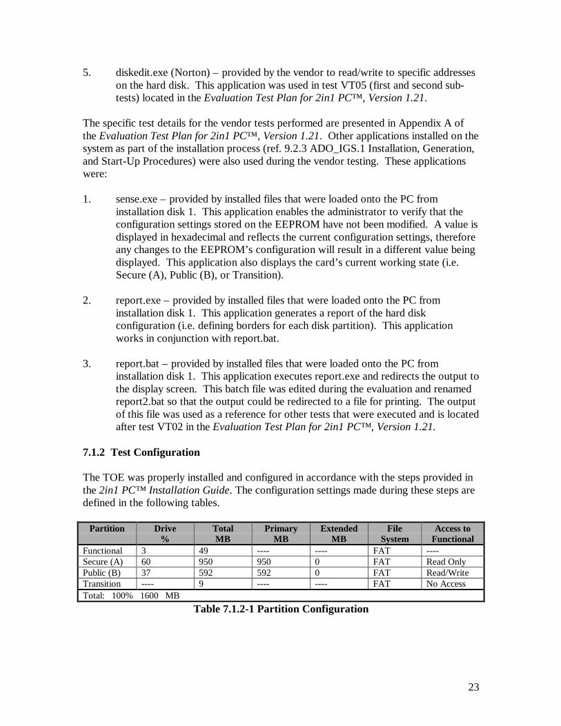
23
5. diskedit.exe (Norton) – provided by the vendor to read/write to specific addresseson the hard disk. This application was used in test VT05 (first and second sub-tests) located in the Evaluation Test Plan for 2in1 PC™ , Version 1.21.
The specific test details for the vendor tests performed are presented in Appendix A ofthe Evaluation Test Plan for 2in1 PC™ , Version 1.21. Other applications installed on thesystem as part of the installation process (ref. 9.2.3 ADO_IGS.1 Installation, Generation,and Start-Up Procedures) were also used during the vendor testing. These applicationswere:
1. sense.exe – provided by installed files that were loaded onto the PC frominstallation disk 1. This application enables the administrator to verify that theconfiguration settings stored on the EEPROM have not been modified. A value isdisplayed in hexadecimal and reflects the current configuration settings, thereforeany changes to the EEPROM’s configuration will result in a different value beingdisplayed. This application also displays the card’s current working state (i.e.Secure (A), Public (B), or Transition).
2. report.exe – provided by installed files that were loaded onto the PC frominstallation disk 1. This application generates a report of the hard diskconfiguration (i.e. defining borders for each disk partition). This applicationworks in conjunction with report.bat.
3. report.bat – provided by installed files that were loaded onto the PC frominstallation disk 1. This application executes report.exe and redirects the output tothe display screen. This batch file was edited during the evaluation and renamedreport2.bat so that the output could be redirected to a file for printing. The outputof this file was used as a reference for other tests that were executed and is locatedafter test VT02 in the Evaluation Test Plan for 2in1 PC™ , Version 1.21.
7.1.2 Test Configuration
The TOE was properly installed and configured in accordance with the steps provided inthe 2in1 PC™ Installation Guide. The configuration settings made during these steps aredefined in the following tables.
Partition Drive%
TotalMB
PrimaryMB
ExtendedMB
FileSystem
Access toFunctional
Functional 3 49 ---- ---- FAT ----Secure (A) 60 950 950 0 FAT Read OnlyPublic (B) 37 592 592 0 FAT Read/WriteTransition ---- 9 ---- ---- FAT No AccessTotal: 100% 1600 MB
Table 7.1.2-1 Partition Configuration

24
Transition Settings Advanced SettingsPower-Up Mode: Menu Reset Signal Advanced
Network Mode 2in1 PC™2nd HD (if exists) A onlyForce Shutdown No
Table 7.1.2-2 Settings Configuration
Changes to the TOE configuration identified in the Tables above were performed for thefollowing vendor tests:
1. VT05 (First Sub-test) – The TOE configuration was modified by changing theaccess to Functional to ‘Read Only’ when the PC is running in the Public (B) diskpartition. This modification was performed to replicate the vendor supplied testprocedures.
2. VT05 (Second Sub-test) – The TOE configuration was modified by changing theaccess to Functional to ‘No Access’ when the PC is running in either the Secure(A) or Public (B) disk partition. This modification was performed to replicate thevendor supplied test procedures.
3. VT06 – The TOE configuration was modified by changing the access toFunctional to ‘No Access’ when the PC is running in either the Secure (A) orPublic (B) disk partition. This modification was performed to replicate thevendor supplied test procedures.
7.1.3 Coverage and Depth Analysis
The developer test documentation evidence was evaluated as to the relevance of theidentified security functions to be tested (ref. 9.2.11 ATE_FUN.1 Functional Testing).The selection of the developer tests was based upon a requirement to verify developerfunctional testing (see Section 9.2.11.2.3 Describe Scenarios) and correspondence to thetests mapped to the 2in1 PC™ Functional Specification. With the confirmation ofdeveloper tests performed by the evaluators, a portion of the security functions within theTSC has been tested. Details of the vendor testing coverage are defined in Table 7.1.3-1Developer Tests Correspondence to Functional Specifications.
Functional Specification Developer Tests1) Allow the setting up and configuration of the2in1 PC™ attributes.2) Provide storage for configuration data(including card configuration and MBRs).
VT01
3) In WORK mode, provide a state machine withthree distinct states of operation: A, B and T(Transition).
Table 7.1.3-1 Developer Tests Correspondence to Functional Specifications
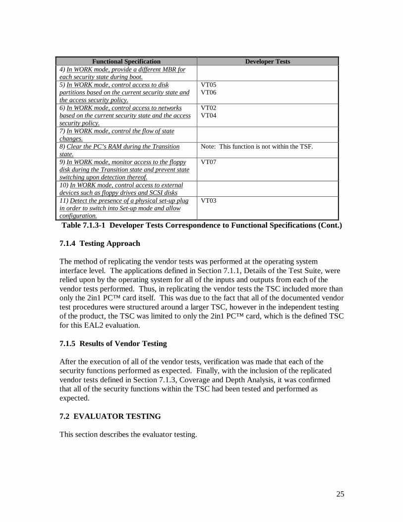
25
Functional Specification Developer Tests4) In WORK mode, provide a different MBR foreach security state during boot.5) In WORK mode, control access to diskpartitions based on the current security state andthe access security policy.
VT05VT06
6) In WORK mode, control access to networksbased on the current security state and the accesssecurity policy.
VT02VT04
7) In WORK mode, control the flow of statechanges.8) Clear the PC’s RAM during the Transitionstate.
Note: This function is not within the TSF.
9) In WORK mode, monitor access to the floppydisk during the Transition state and prevent stateswitching upon detection thereof.
VT07
10) In WORK mode, control access to externaldevices such as floppy drives and SCSI disks11) Detect the presence of a physical set-up plugin order to switch into Set-up mode and allowconfiguration.
VT03
Table 7.1.3-1 Developer Tests Correspondence to Functional Specifications (Cont.)
7.1.4 Testing Approach
The method of replicating the vendor tests was performed at the operating systeminterface level. The applications defined in Section 7.1.1, Details of the Test Suite, wererelied upon by the operating system for all of the inputs and outputs from each of thevendor tests performed. Thus, in replicating the vendor tests the TSC included more thanonly the 2in1 PC™ card itself. This was due to the fact that all of the documented vendortest procedures were structured around a larger TSC, however in the independent testingof the product, the TSC was limited to only the 2in1 PC™ card, which is the defined TSCfor this EAL2 evaluation.
7.1.5 Results of Vendor Testing
After the execution of all of the vendor tests, verification was made that each of thesecurity functions performed as expected. Finally, with the inclusion of the replicatedvendor tests defined in Section 7.1.3, Coverage and Depth Analysis, it was confirmedthat all of the security functions within the TSC had been tested and performed asexpected.
7.2 EVALUATOR TESTING
This section describes the evaluator testing.
26
7.2.1 Details of the Test Suite
The platform used during the TOE independent testing is defined as:
Computer: Twinbrook Systems, Intel 200Mhz Pentium-MMXMothercard: TX ChipsetHard Disk: Seagate hard disk; model ST31720A, 1,705MBBIOS Information: Award Modular BIOS Version 5.41PGM/Award Plug and
Play BIOS Extension V1.0AISA Slot Cards: Voltaire 2in1 PC™ , Version 1.21
Generic PIC Combo Network Interface Card (NIC) Generic 16Bit SoundBlaster Compatible Sound Card Diamond Stealth 4MB PCI Video Card / 3D 2000 Pro Generic 33.6K Compatible Modem
Other: 32 MB SDRAM 24X LG CD-ROM Model CRD-8240B Generic 3.5” 1.44MB NEC Floppy Diskette Drive 512K L2 Pipeline Burst CacheOperating System Used for Evaluation: DOS 7, Windows 952in1 PC™ Drivers: Operating System DependentOther Software: 2in1 PC™ Configuration Information from the 2in1 PC™
Installation Diskettes, Version 1.21 (2 Disks)
The test suite used during the execution of the independent tests included:
1. Twinbrook Systems, Intel 200Mhz Pentium-MMX – provided by the testing lab.
2. Innotec ID520 IDE Analyzer – provided by Voltaire. This device was used intests ET03 and ET04 that are defined in the Evaluation Test Plan for 2in1 PC™ ,Version 1.21 Plan.
3. Faxconn ISA Slot Extension Card – provided by Voltaire. This device was used inall of the independent tests to provide easy access to the 2in1 PC™ cardcomponents.
4. HP 545A Logic Probe – provided by Voltaire. This device was used inconjunction with the 2in1 PC™ Hardware Design document to verifyconnections on the 2in1 PC™ card. This device was used in independentevaluator tests as identified in the Evaluation Test Plan for 2in1 PC™ , Version1.21.
5. HP 1660A Logic Analyzer (50/100-MHz State/500-MHz Timing) – provided bythe testing lab. This device was used in test ET02 located in the Evaluation TestPlan for 2in1 PC™ , Version 1.21.
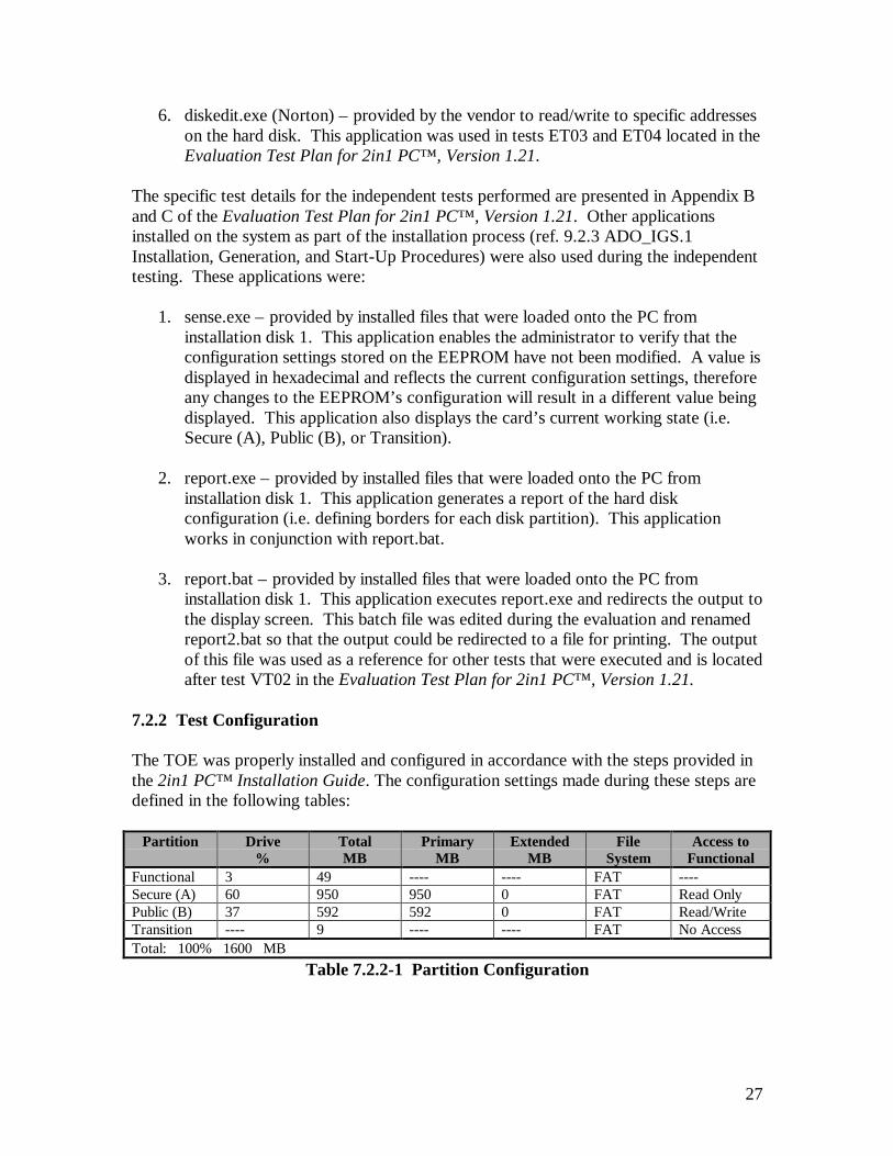
27
6. diskedit.exe (Norton) – provided by the vendor to read/write to specific addresseson the hard disk. This application was used in tests ET03 and ET04 located in theEvaluation Test Plan for 2in1 PC™ , Version 1.21.
The specific test details for the independent tests performed are presented in Appendix Band C of the Evaluation Test Plan for 2in1 PC™ , Version 1.21. Other applicationsinstalled on the system as part of the installation process (ref. 9.2.3 ADO_IGS.1Installation, Generation, and Start-Up Procedures) were also used during the independenttesting. These applications were:
1. sense.exe – provided by installed files that were loaded onto the PC frominstallation disk 1. This application enables the administrator to verify that theconfiguration settings stored on the EEPROM have not been modified. A value isdisplayed in hexadecimal and reflects the current configuration settings, thereforeany changes to the EEPROM’s configuration will result in a different value beingdisplayed. This application also displays the card’s current working state (i.e.Secure (A), Public (B), or Transition).
2. report.exe – provided by installed files that were loaded onto the PC frominstallation disk 1. This application generates a report of the hard diskconfiguration (i.e. defining borders for each disk partition). This applicationworks in conjunction with report.bat.
3. report.bat – provided by installed files that were loaded onto the PC frominstallation disk 1. This application executes report.exe and redirects the output tothe display screen. This batch file was edited during the evaluation and renamedreport2.bat so that the output could be redirected to a file for printing. The outputof this file was used as a reference for other tests that were executed and is locatedafter test VT02 in the Evaluation Test Plan for 2in1 PC™ , Version 1.21.
7.2.2 Test Configuration
The TOE was properly installed and configured in accordance with the steps provided inthe 2in1 PC™ Installation Guide. The configuration settings made during these steps aredefined in the following tables:
Partition Drive%
TotalMB
PrimaryMB
ExtendedMB
FileSystem
Access toFunctional
Functional 3 49 ---- ---- FAT ----Secure (A) 60 950 950 0 FAT Read OnlyPublic (B) 37 592 592 0 FAT Read/WriteTransition ---- 9 ---- ---- FAT No AccessTotal: 100% 1600 MB
Table 7.2.2-1 Partition Configuration
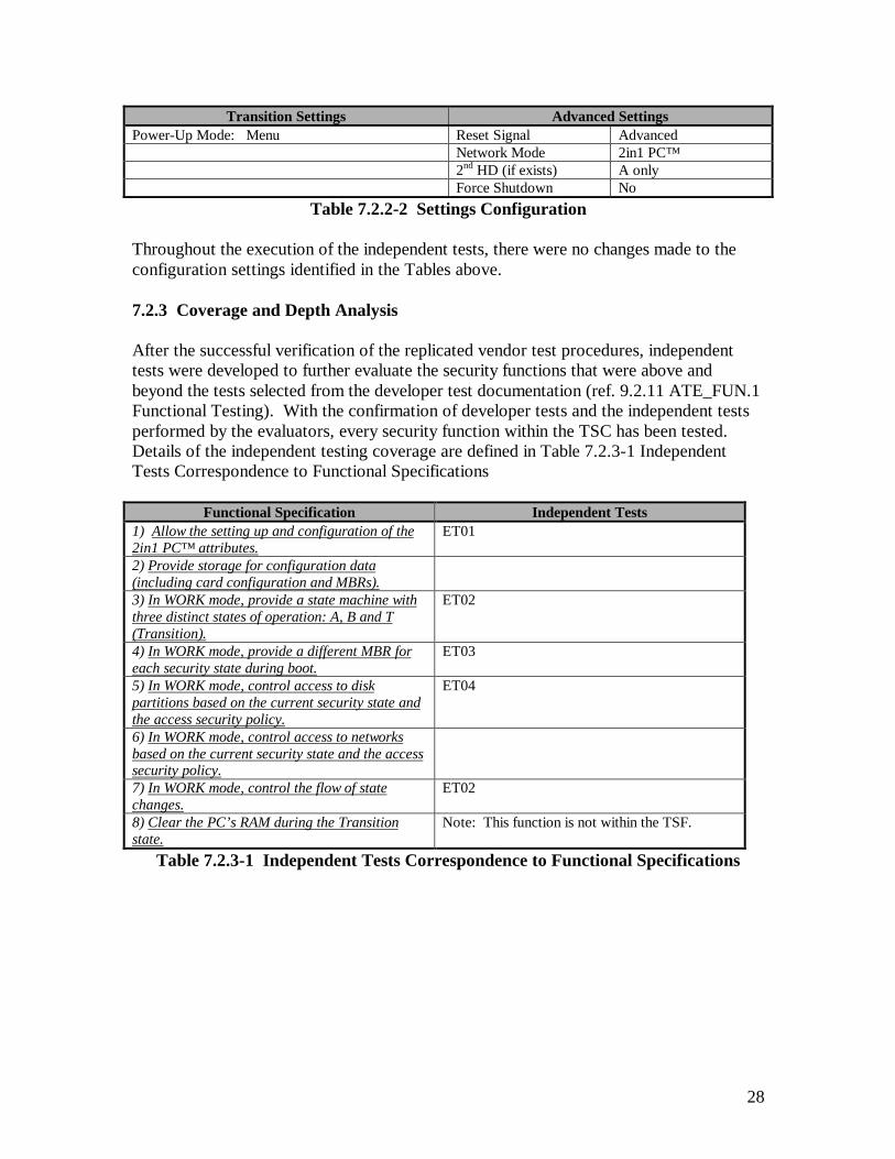
28
Transition Settings Advanced SettingsPower-Up Mode: Menu Reset Signal Advanced
Network Mode 2in1 PC™2nd HD (if exists) A onlyForce Shutdown No
Table 7.2.2-2 Settings Configuration
Throughout the execution of the independent tests, there were no changes made to theconfiguration settings identified in the Tables above.
7.2.3 Coverage and Depth Analysis
After the successful verification of the replicated vendor test procedures, independenttests were developed to further evaluate the security functions that were above andbeyond the tests selected from the developer test documentation (ref. 9.2.11 ATE_FUN.1Functional Testing). With the confirmation of developer tests and the independent testsperformed by the evaluators, every security function within the TSC has been tested.Details of the independent testing coverage are defined in Table 7.2.3-1 IndependentTests Correspondence to Functional Specifications
Functional Specification Independent Tests1) Allow the setting up and configuration of the2in1 PC™ attributes.
ET01
2) Provide storage for configuration data(including card configuration and MBRs).3) In WORK mode, provide a state machine withthree distinct states of operation: A, B and T(Transition).
ET02
4) In WORK mode, provide a different MBR foreach security state during boot.
ET03
5) In WORK mode, control access to diskpartitions based on the current security state andthe access security policy.
ET04
6) In WORK mode, control access to networksbased on the current security state and the accesssecurity policy.7) In WORK mode, control the flow of statechanges.
ET02
8) Clear the PC’s RAM during the Transitionstate.
Note: This function is not within the TSF.
Table 7.2.3-1 Independent Tests Correspondence to Functional Specifications
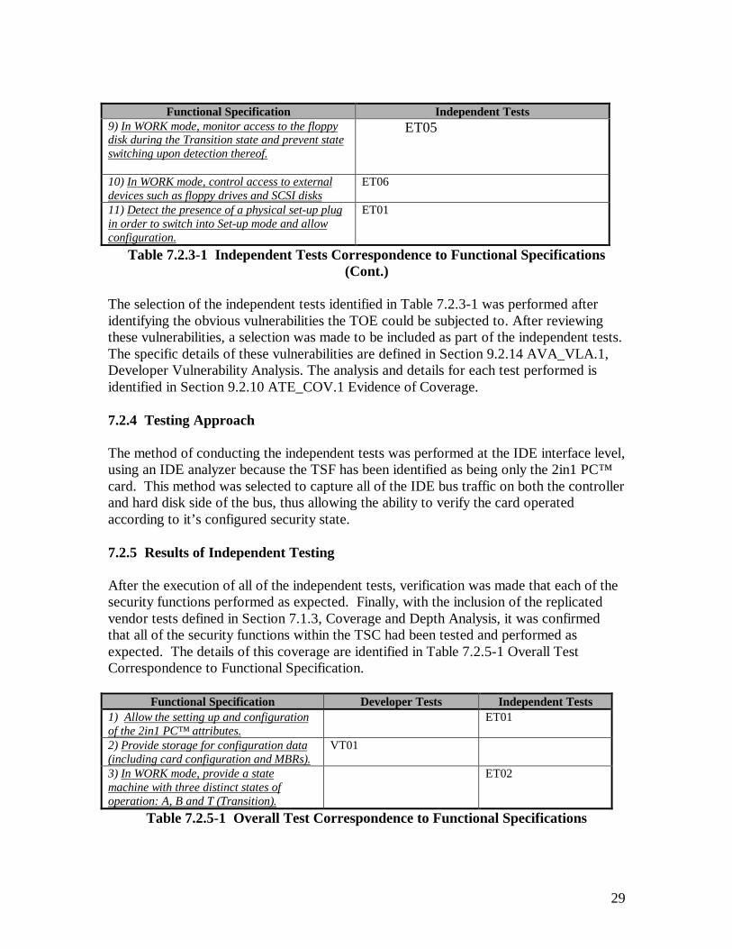
29
Functional Specification Independent Tests9) In WORK mode, monitor access to the floppydisk during the Transition state and prevent stateswitching upon detection thereof.
ET05
10) In WORK mode, control access to externaldevices such as floppy drives and SCSI disks
ET06
11) Detect the presence of a physical set-up plugin order to switch into Set-up mode and allowconfiguration.
ET01
Table 7.2.3-1 Independent Tests Correspondence to Functional Specifications(Cont.)
The selection of the independent tests identified in Table 7.2.3-1 was performed afteridentifying the obvious vulnerabilities the TOE could be subjected to. After reviewingthese vulnerabilities, a selection was made to be included as part of the independent tests.The specific details of these vulnerabilities are defined in Section 9.2.14 AVA_VLA.1,Developer Vulnerability Analysis. The analysis and details for each test performed isidentified in Section 9.2.10 ATE_COV.1 Evidence of Coverage.
7.2.4 Testing Approach
The method of conducting the independent tests was performed at the IDE interface level,using an IDE analyzer because the TSF has been identified as being only the 2in1 PC™card. This method was selected to capture all of the IDE bus traffic on both the controllerand hard disk side of the bus, thus allowing the ability to verify the card operatedaccording to it’s configured security state.
7.2.5 Results of Independent Testing
After the execution of all of the independent tests, verification was made that each of thesecurity functions performed as expected. Finally, with the inclusion of the replicatedvendor tests defined in Section 7.1.3, Coverage and Depth Analysis, it was confirmedthat all of the security functions within the TSC had been tested and performed asexpected. The details of this coverage are identified in Table 7.2.5-1 Overall TestCorrespondence to Functional Specification.
Functional Specification Developer Tests Independent Tests1) Allow the setting up and configurationof the 2in1 PC™ attributes.
ET01
2) Provide storage for configuration data(including card configuration and MBRs).
VT01
3) In WORK mode, provide a statemachine with three distinct states ofoperation: A, B and T (Transition).
ET02
Table 7.2.5-1 Overall Test Correspondence to Functional Specifications
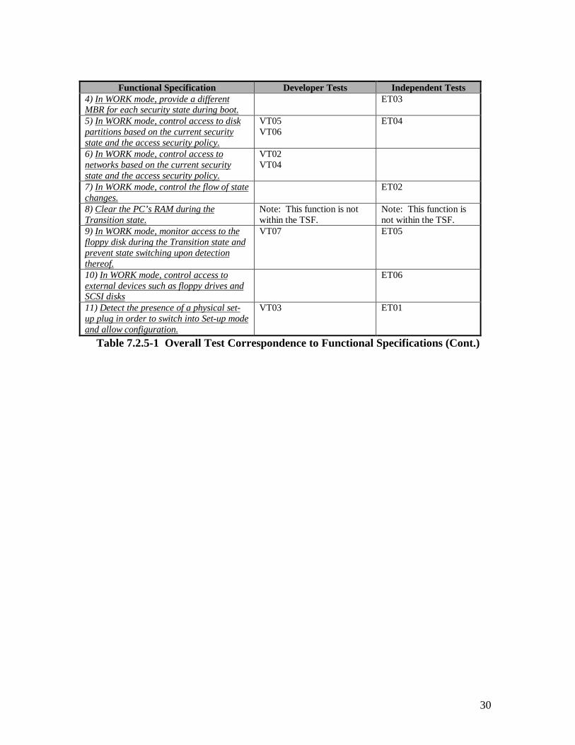
30
Functional Specification Developer Tests Independent Tests4) In WORK mode, provide a differentMBR for each security state during boot.
ET03
5) In WORK mode, control access to diskpartitions based on the current securitystate and the access security policy.
VT05VT06
ET04
6) In WORK mode, control access tonetworks based on the current securitystate and the access security policy.
VT02VT04
7) In WORK mode, control the flow of statechanges.
ET02
8) Clear the PC’s RAM during theTransition state.
Note: This function is notwithin the TSF.
Note: This function isnot within the TSF.
9) In WORK mode, monitor access to thefloppy disk during the Transition state andprevent state switching upon detectionthereof.
VT07 ET05
10) In WORK mode, control access toexternal devices such as floppy drives andSCSI disks
ET06
11) Detect the presence of a physical set-up plug in order to switch into Set-up modeand allow configuration.
VT03 ET01
Table 7.2.5-1 Overall Test Correspondence to Functional Specifications (Cont.)
31
SECTION 8
EVALUATED CONFIGURATION
8 EVALUATED CONFIGURATION
This section describes the evaluated configuration for the TOE. The purpose of anevaluated configuration is to define the hardware and software components that wereexamined by the evaluation team. Furthermore, based upon the assumptions defined inSection 4, Assumptions and Clarification of Scope, guidance on how to configure andoperate the TOE in a secure manner is also identified.
8.1 EVALUATED HARDWARE AND SOFTWARE COMPONENTS
This section identifies the hardware and software components that were examined by theevaluation team (ref. Section 7 Product Testing). The examined hardware and softwarecomponents are identified for both the vendor replicated tests and the independentevaluator tests performed. A rationale is also provided to explain the overall scope of thecomponents selected.
8.1.1 Evaluated Hardware Components
The hardware component examined by the evaluators was the 2in1 PC™ ISA slot PCcard. Table 8.1.1-1 Evaluated 2in1 PC™ Card List, identifies the evaluated componentson the 2in1 PC™ card, provides a description of each element’s security function andprovides a rationale as to why the component was selected. The actions enforced by eachcomponent were verified by the evaluators, Section 7 Product Testing provides furtherdetails of this verification.
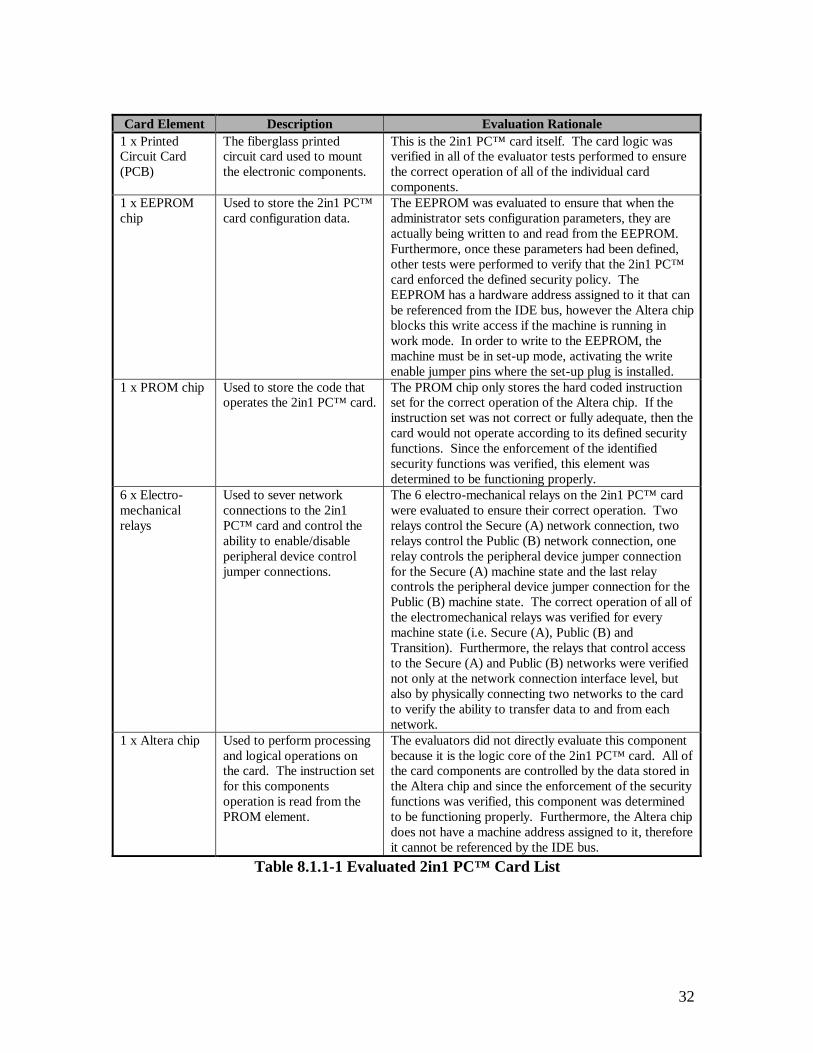
32
Card Element Description Evaluation Rationale1 x PrintedCircuit Card(PCB)
The fiberglass printedcircuit card used to mountthe electronic components.
This is the 2in1 PC™ card itself. The card logic wasverified in all of the evaluator tests performed to ensurethe correct operation of all of the individual cardcomponents.
1 x EEPROMchip
Used to store the 2in1 PC™card configuration data.
The EEPROM was evaluated to ensure that when theadministrator sets configuration parameters, they areactually being written to and read from the EEPROM.Furthermore, once these parameters had been defined,other tests were performed to verify that the 2in1 PC™card enforced the defined security policy. TheEEPROM has a hardware address assigned to it that canbe referenced from the IDE bus, however the Altera chipblocks this write access if the machine is running inwork mode. In order to write to the EEPROM, themachine must be in set-up mode, activating the writeenable jumper pins where the set-up plug is installed.
1 x PROM chip Used to store the code thatoperates the 2in1 PC™ card.
The PROM chip only stores the hard coded instructionset for the correct operation of the Altera chip. If theinstruction set was not correct or fully adequate, then thecard would not operate according to its defined securityfunctions. Since the enforcement of the identifiedsecurity functions was verified, this element wasdetermined to be functioning properly.
6 x Electro-mechanicalrelays
Used to sever networkconnections to the 2in1PC™ card and control theability to enable/disableperipheral device controljumper connections.
The 6 electro-mechanical relays on the 2in1 PC™ cardwere evaluated to ensure their correct operation. Tworelays control the Secure (A) network connection, tworelays control the Public (B) network connection, onerelay controls the peripheral device jumper connectionfor the Secure (A) machine state and the last relaycontrols the peripheral device jumper connection for thePublic (B) machine state. The correct operation of all ofthe electromechanical relays was verified for everymachine state (i.e. Secure (A), Public (B) andTransition). Furthermore, the relays that control accessto the Secure (A) and Public (B) networks were verifiednot only at the network connection interface level, butalso by physically connecting two networks to the cardto verify the ability to transfer data to and from eachnetwork.
1 x Altera chip Used to perform processingand logical operations onthe card. The instruction setfor this componentsoperation is read from thePROM element.
The evaluators did not directly evaluate this componentbecause it is the logic core of the 2in1 PC™ card. All ofthe card components are controlled by the data stored inthe Altera chip and since the enforcement of the securityfunctions was verified, this component was determinedto be functioning properly. Furthermore, the Altera chipdoes not have a machine address assigned to it, thereforeit cannot be referenced by the IDE bus.
Table 8.1.1-1 Evaluated 2in1 PC™ Card List
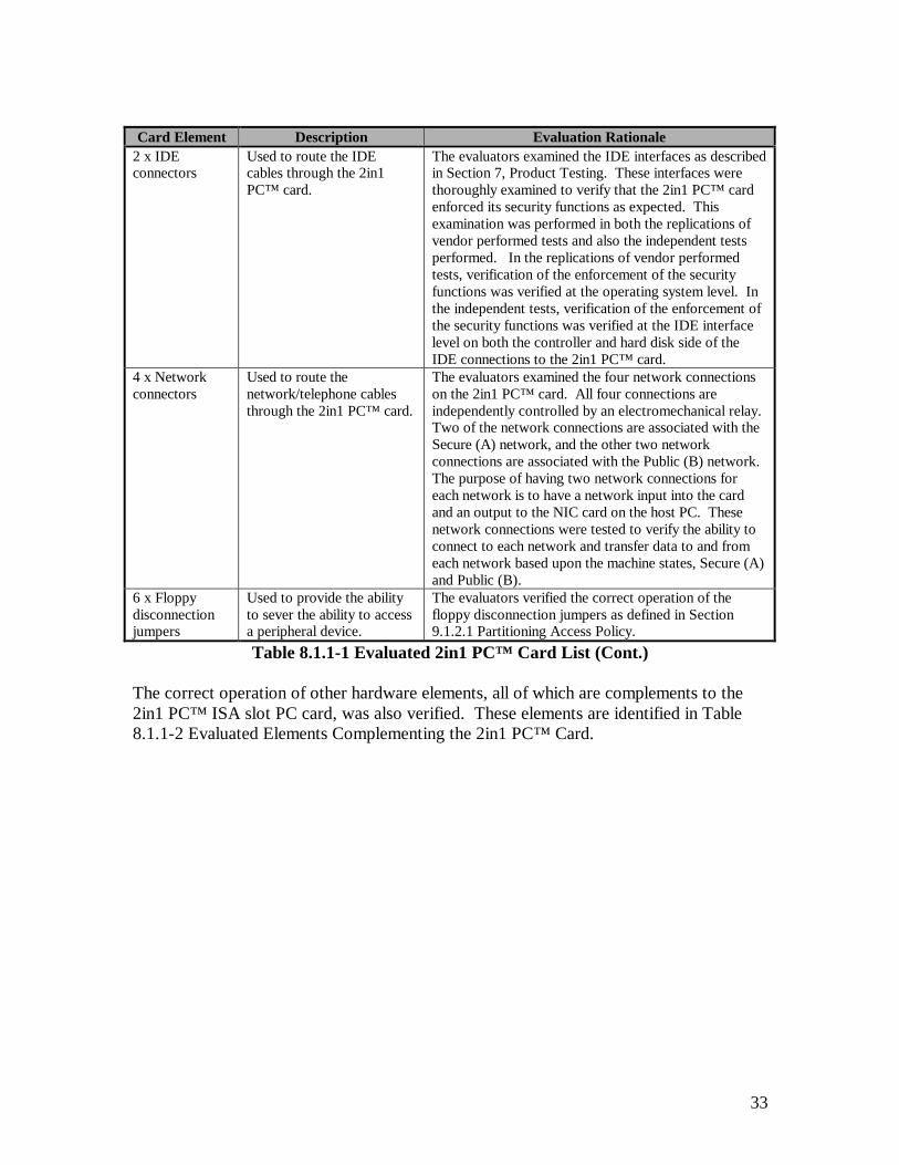
33
Card Element Description Evaluation Rationale2 x IDEconnectors
Used to route the IDEcables through the 2in1PC™ card.
The evaluators examined the IDE interfaces as describedin Section 7, Product Testing. These interfaces werethoroughly examined to verify that the 2in1 PC™ cardenforced its security functions as expected. Thisexamination was performed in both the replications ofvendor performed tests and also the independent testsperformed. In the replications of vendor performedtests, verification of the enforcement of the securityfunctions was verified at the operating system level. Inthe independent tests, verification of the enforcement ofthe security functions was verified at the IDE interfacelevel on both the controller and hard disk side of theIDE connections to the 2in1 PC™ card.
4 x Networkconnectors
Used to route thenetwork/telephone cablesthrough the 2in1 PC™ card.
The evaluators examined the four network connectionson the 2in1 PC™ card. All four connections areindependently controlled by an electromechanical relay.Two of the network connections are associated with theSecure (A) network, and the other two networkconnections are associated with the Public (B) network.The purpose of having two network connections foreach network is to have a network input into the cardand an output to the NIC card on the host PC. Thesenetwork connections were tested to verify the ability toconnect to each network and transfer data to and fromeach network based upon the machine states, Secure (A)and Public (B).
6 x Floppydisconnectionjumpers
Used to provide the abilityto sever the ability to accessa peripheral device.
The evaluators verified the correct operation of thefloppy disconnection jumpers as defined in Section9.1.2.1 Partitioning Access Policy.
Table 8.1.1-1 Evaluated 2in1 PC™ Card List (Cont.)
The correct operation of other hardware elements, all of which are complements to the2in1 PC™ ISA slot PC card, was also verified. These elements are identified in Table8.1.1-2 Evaluated Elements Complementing the 2in1 PC™ Card.

34
Card Element Description Evaluation Rationale1 x Internal Set-upplug
Used to enable the write function toalter the EEPROM configurationsettings and allows for fullunmonitored IDE access to the harddisk(s).
This component was used during theinstallation procedure to configure the2in1 PC™ card on the host PC. It wasalso used to reconfigure the 2in1 PC™card to verify the expected results fromthe replicated vendor tests (ref. Section7,Product Testing).
1 x Internal EnablerPlug(Note: This is anoptional device,however itsfunctionality wasverified).
Used in conjunction with the externalset-up plug to enable the writefunction to alter the EEPROMconfiguration settings and to allowfull unmonitored IDE access to thehard disk(s). With the internalenabler plug inserted on the 2in1PC™ card, the external set-up plugcan be used in lieu of the internal set-up plug.
This component, used in conjunctionwith the external set-up plug, wasexamined to verify that the functionalityprovided is the same as with the internalset-up plug.
1 x External Set-upPlug(Note: This is anoptional device,however itsfunctionality wasverified).
Used in conjunction with the internalenabler plug to enable the writefunction to alter the EEPROMconfiguration settings and to allowfor full unmonitored IDE access tothe hard disk(s). With the internalenabler plug inserted on the 2in1PC™ card, the external set-up plugcan be used in lieu of the internal set-up plug.
This component, used in conjunctionwith the internal enabler plug, wasexamined to verify that the functionalityprovided is the same as with the internalset-up plug.
1 x Floppy DiskControl Cable(Note: This is anoptional device,however itsfunctionality wasverified).
This cable replaces the floppy drivecable on the host PC. This cable isinstalled on the host PC in the samemanner as the old cable, however ithas a spliced control signal wire thatis connected to the peripheral devicecontrol jumpers on the 2in1 PC™card. These jumpers are controlledby two electro-mechanical relays.One relay controls the jumpers forthe Secure (A) machine state and theother relay controls the jumpers forthe Public (B) machine state.
This component was examined to verifythe ability to enable/disable access to thefloppy diskette drive. This wasperformed by connecting the floppy diskcontrol cable onto the host PC and thenconnecting the severed control signalwire to the floppy disconnectionjumpers.
Table 8.1.1-2 Evaluated Elements Complementing the 2in1 PC™ Card
8.1.2 Evaluated Software Components
The software components examined by the evaluators were the two installation diskettesprovided as part of the TOE for the installation and configuration of the card on the hostPC. The extent of this examination was limited to only the verification of a secureconfiguration of the TOE as defined in Section 9.2.3 ADO_IGS.1 Installation,Generation, and Start-up Procedures. The individual software elements stored on eachdisk (ref. 9.2.1.2.3 Configuration List) were not independently evaluated in Section 7Product Testing, because they were defined to be outside the scope of the TSF. The area
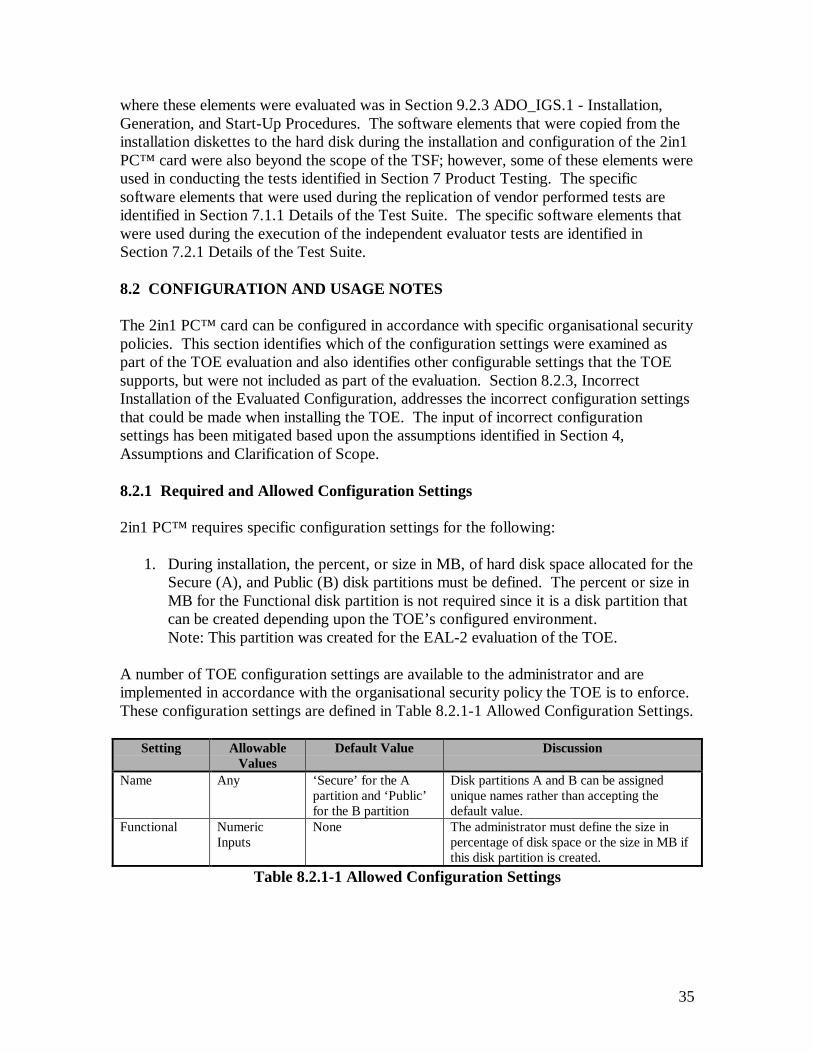
35
where these elements were evaluated was in Section 9.2.3 ADO_IGS.1 - Installation,Generation, and Start-Up Procedures. The software elements that were copied from theinstallation diskettes to the hard disk during the installation and configuration of the 2in1PC™ card were also beyond the scope of the TSF; however, some of these elements wereused in conducting the tests identified in Section 7 Product Testing. The specificsoftware elements that were used during the replication of vendor performed tests areidentified in Section 7.1.1 Details of the Test Suite. The specific software elements thatwere used during the execution of the independent evaluator tests are identified inSection 7.2.1 Details of the Test Suite.
8.2 CONFIGURATION AND USAGE NOTES
The 2in1 PC™ card can be configured in accordance with specific organisational securitypolicies. This section identifies which of the configuration settings were examined aspart of the TOE evaluation and also identifies other configurable settings that the TOEsupports, but were not included as part of the evaluation. Section 8.2.3, IncorrectInstallation of the Evaluated Configuration, addresses the incorrect configuration settingsthat could be made when installing the TOE. The input of incorrect configurationsettings has been mitigated based upon the assumptions identified in Section 4,Assumptions and Clarification of Scope.
8.2.1 Required and Allowed Configuration Settings
2in1 PC™ requires specific configuration settings for the following:
1. During installation, the percent, or size in MB, of hard disk space allocated for theSecure (A), and Public (B) disk partitions must be defined. The percent or size inMB for the Functional disk partition is not required since it is a disk partition thatcan be created depending upon the TOE’s configured environment.Note: This partition was created for the EAL-2 evaluation of the TOE.
A number of TOE configuration settings are available to the administrator and areimplemented in accordance with the organisational security policy the TOE is to enforce.These configuration settings are defined in Table 8.2.1-1 Allowed Configuration Settings.
Setting AllowableValues
Default Value Discussion
Name Any ‘Secure’ for the Apartition and ‘Public’for the B partition
Disk partitions A and B can be assignedunique names rather than accepting thedefault value.
Functional NumericInputs
None The administrator must define the size inpercentage of disk space or the size in MB ifthis disk partition is created.
Table 8.2.1-1 Allowed Configuration Settings

36
Setting AllowableValues
Default Value Discussion
Access toFunctional,Secure (A)
Read/Write,Read Only, orNo Access
Read Only Read/Write-Sets the Secure (A) machine tohave the ability to write data to and read datafrom the Functional disk partition.
Read Only-Sets the Secure (A) machine toonly have the ability to read data from theFunctional disk partition.
No Access-Sets the Secure (A) machine tohave no ability to access the data stored in theFunctional disk partition.
Access toFunctional,Public (B)
Read/Write,Read Only, orNo Access
Read/Write Read/Write-Sets the Public (B) machine tohave the ability to write data to and read datafrom the Functional disk partition.
Read Only-Sets the Public (B) machine toonly have the ability to read data from theFunctional disk partition.
No Access-Sets the Public (B) machine tohave no ability to access the data stored in theFunctional disk partition.
Access toFunctional,Transition
Read/Write,Read Only, orNo Access
No Access Read/Write-Sets the Transition machine tohave the ability to write data to and read datafrom the Functional disk partition.
Read Only-Sets the Transition machine toonly have the ability to read data from theFunctional disk partition.
No Access-Sets the Transition machine tohave no ability to access the data stored in theFunctional disk partition.
Power-UpMode
A, B, or Menu A A-Sets the PC during first power on to bootinto Transition and then reboot into theSecure (A) machine state.
B-Sets the PC during first power on to bootinto Transition and then reboot into thePublic (B) machine state.
Transition-Sets the PC during first power onto boot into Transition and then displays amenu for the user to select whether to rebootthe PC into the Secure (A) or Public (B)machine state.
Table 8.2.1-1 Allowed Configuration Settings (Cont.)

37
Setting AllowableValues
Default Value Discussion
Reset Signal Advanced orATCompatible
Advanced Advanced-Set to match the reset signalmethod used on the host PC (IDE Reset).
AT Compatible-Set to match the reset signalmethod used on the host PC (ISA64 Reset).
Note: If this setting is not properlyconfigured, the TOE will ignore the resetsignal that has been sent.
Network Mode 2in1 PC, or2in1 Net
2in1 PC 2in1 PC-Set if to allow the user on the hostPC to control the machine states.
2in1 Net-Set if the optional (not evaluated)2in1 Net device will be used to control themachine states of a group of host PC’s thathave the 2in1 PC™ card installed on them.
2nd HD (ifexists)
A Only, BOnly.
A A Only-Set to allow only the Secure (A)machine state the ability to access thesecondary slave hard disk.
B Only-Set to allow only the Public (B)machine state the ability to access thesecondary slave hard disk.
ForceShutdown
Yes, or No No Yes-Sets the Host PC to fully power downwhen switching between machine statesSecure (A) and Public (B).
No-Sets the host PC to perform a soft-bootwhen switching between machine statesSecure (A) and Public (B).
Table 8.2.1-1 Allowed Configuration Settings (Cont.)
The configuration settings defined in Table 8.2.1-1 Allowed Configuration Settings onlyapply to the configuration of the 2in1 PC™ card during the installation of the TOE. Afterthe installation has been completed, the only parameters that cannot be modified withoutreinstalling the TOE on the host system are the partition sizes on the master disk for theSecure (A), Public (B), Transition and Functional disk partition. These configurationsettings only apply to the 2in1 PC™ card itself.
The operating environment must address other devices or connections that are to becontrolled by the 2in1 PC™ card. This includes:
1. Proper connection of the network wires to the 2in1 PC™ card. If the networkconnections are not connected to the 2in1 PC™ card as defined in the 2in1 PCInstallation Guide, then the result will be no network connectivity.
2. Proper connection of the peripheral device control cables to the jumperconnections on the 2in1 PC™ card (these cables are optional and supplied by
38
Voltaire). If the cable connections are not properly inserted onto the correctjumpers on the 2in1 PC™ card as defined in the 2in1 PC Installation Guide, thenthe controlled device on the host PC will be disabled/enabled for the wrongmachine states.
3. Proper connection of the IDE cables from the motherboard to the 2in1 PC™ cardand from the 2in1 PC™ card to the hard disk(s). If the IDE cables are notproperly installed on the 2in1 PC™ card, then the host PC will not function.
8.2.2 Evaluated Configuration Settings
The following TOE configuration settings were not tested in Section 7 Product Testingand Section 9.2.3 ADO_IGS.1 – Installation, Generation, and Start-Up Procedures (refTable 8.2.1-1 Allowed Configuration Settings):
1. Name- Names were not reassigned to the ‘Secure’ (A) or ‘Public’ (B) diskpartitions.
2. Functional- The creation of the Functional disk partition was not omitted duringthe installation process (ref. 9.2.3 ADO_IGS.1 Installation, Generation, and Start-up Procedures).
3. Access to Functional, Secure (A)- ‘Read/Write’ access to the Functional diskpartition while running in the Secure (A) machine state was not tested.
4. Access to Functional, Transition- ‘Read/Write’ and ‘Read Only’ access to theFunctional disk partition while running in the Transition machine state was nottested.
5. Power-Up Mode- During first power on of the PC, Power-Up Mode ‘B’ was nottested.
6. Reset Signal- The ‘AT Compatible’ reset signal was not tested.
7. 2nd HD (if exists)- The configuration of the TOE did not include the existence of asecond hard disk, therefore the selections ‘A Only’ and ‘B Only’ were not tested.
8. Force Shutdown- The selection ‘Yes’ was not tested.
8.2.3 Non-Evaluated Configuration Settings
The following TOE configuration settings were not evaluated:
1) Network Mode- The ‘2in1 Net’ selection was not evaluated.
39
8.2.4 Incorrect Installation of the Evaluated Configuration
The administrator must select the appropriate TOE configuration settings in order toenforce their organisational security policy. The specific TOE configuration settings that,if not properly configured, will result in a violation of any organisational security policyinclude:
1. Defining incorrect values for the Secure (A) machine’s ability to pass data toand/or from the Functional disk partition.
2. Defining incorrect values for the Public (B) machine’s ability to pass data toand/or from the Functional disk partition.
The operational environment must address the incorrect installation of other devices orconnections that are to be controlled by the 2in1 PC™ card. These connections include:
1. Network Connections: If the network connections are not connected to the 2in1PC™ card as defined in the 2in1 PC Installation Guide, then the result will be nonetwork connectivity.
2. Peripheral device control cables: If the cable connections are not properly insertedonto the correct jumpers on the 2in1 PC™ card as defined in the 2in1 PCInstallation Guide, then the controlled device on the host PC will bedisabled/enabled for the wrong machine states.
3. IDE Cables: If the IDE cables are not properly installed on the 2in1 PC™ card asdefined in the 2in1 PC Installation Guide, then the host PC will not function.
8.3 TARGET ENVIRONMENT
The TOE is a COTS system that is intended to be installed on a PC that is located in acontrolled environment. The operational environment must provide basic physicalsecurity. Other requirements for the target environment include:
1. Users of the TOE must recognise the need for a secure IT environment.
2. Administrators must be adequately trained to competently administer the securityfeatures of the TOE during set-up and reconfiguration.
3. Users of the TOE system must be trusted not to modify the hardwareconfiguration.
8.4 RESIDUAL VULNERABILITIES
The TOE vulnerabilities are identified in Section 9.2.14, Developer VulnerabilityAnalysis. Along with the identification of residual vulnerabilities, this section also

40
defines how each vulnerability is mitigated by either environmental assumptions orpolicies, or how each vulnerability is mitigated based upon the logic used on the 2in1PC™ card.

41
SECTION 9
RESULTS OF EVALUATION
9 RESULTS OF EVALUATION
This section provides descriptions of how the TOE meets each of the Security FunctionalRequirements and Assurance Requirements of the 2in1 PC™ Security Target Report.
9.1 SECURITY FUNCTIONAL REQUIREMENTS
Table 9.1-1 lists the security functional requirements from the 2in1 PC™ Security TargetReport.
Security Functional Requirement DescriptionFDP_ACC.1 Subset Access ControlFDP_ACF.1 Security Attribute Based Access ControlFDP_ITC.1 Import of User Data Without Security AttributesFIA_UID.2 User Identification Before Any ActionFMT_MSA.1 Management of Security AttributesFMT_MSA.3 Static Attribute InitialisationFMT_SMR.1 Security RolesFMT_SMR.3 Assuming RolesFPT_FLS.1 Failure with Preservation of Secure StateFPT_RCV.4 Function RecoveryFPT_RVM.1 Non-Bypassability of the TSPFPT_SEP.3 Complete Reference Monitor
Table 9.1-1 Security Functional Requirements
9.1.1 FDP_ACC.1 Subset Access Control
Subset access control requires that each identified access control SFP be in place for asubset of the possible operations, on a subset of the objects in the TOE.
9.1.1.1 FDP_ACC.1.1 – Partitioning Access Policy
The TSF shall enforce the [Partitioning Access Policy] on [the user’s current machinestate: “A”, “B” and “T”; disk partitions: Transition, Functional, “A”, and “B”;network connections: “A” and “B”; and other devices controlled by the PartitioningAccess Policy].
This element was satisfied by the TOE. In the Partitioning Access Policy, the onlysubjects are users and processes running on behalf of users. The objects are diskpartitions, network connections, and other devices controlled by the TSF. The
42
Partitioning Access Policy described in Section 3.1 is enforced by a combination ofsecurity functions specified in the 2in1 PC™ Functional Specification. A state machine ismaintained that provides three user states: A, B, and Transition. While in any given state,the IDE bus monitor permits only IDE hard disk addresses that are within the boundariesof disk partitions to which the user is allowed access, according to the PartitioningAccess Policy. The IDE bus monitor also permits only IDE hard disk operations (e.g.,read/write) that are allowed for the partition, according to the Partitioning Access Policy.The TSF sets and resets relays that control network access in accordance with thePartitioning Access Policy. Other optional interfaces may be controlled by the TSF. Theadministrator may configure the optional interfaces with special ribbon cables suppliedby Voltaire. These ribbon cables have a jumper that connects to pins on the 2in1 PC™card to enable or disable their use in specific user states. Devices so connected arecontrolled by the TSF.
9.1.1.2 FDP_ACC.1.1 – Administrator Access Policy
The TSF shall enforce the [Administrator Access Policy] on [the user roles:administrator and user; for write access to the EEPROM].
This element was satisfied by the TOE. The TOE implements a role based access policyproviding the administrator the ability to set-up and modify some of the attributes andparameters used by the Partitioning Access Policy. The Administrator Access Policy isdescribed in Section 3.2. Write access to the EEPROM is physically prohibited while inwork mode. When the administrator has been identified, by detection of the set-up plugbeing inserted on the 2in1 PC™ card, they are put into set-up mode and write access tothe EEPROM is physically enabled (the PC must be powered off to insert the set-up plug,then powered back on to enter set-up mode).
9.1.1.3 Dependencies
9.1.1.3.1 FDP_ACF.1 – Security Attribute Based Access Control
The TSF meets the requirement for this condition by providing security attribute basedaccess control. (See Section 9.1.2.)
9.1.2 FDP_ACF.1 Security Attribute Based Access Control
This element was satisfied by the TSF. The TSF has two access control policies that areenforced by the TSF. The first is the Partitioning Access Policy, which controls accessbetween users and the objects that they normally access (i.e., disk partitions, networkconnections, and other interfaces) while in work mode. The second policy is theAdministrator Access Policy, which controls write access to the EEPROM. TheEEPROM is where many of the security parameters and attributes that are used to controlthe Partitioning Access Policy are stored.
43
9.1.2.1 Partitioning Access Policy
The following requirements apply to the Partitioning Access Policy.
9.1.2.1.1 FDP_ACF.1.1 – Partitioning Access Policy
The TSF shall enforce the [Partitioning Access Policy] to objects based on [the user’scurrently active machine state, disk partition address, network connection type, and pinconnection for external devices controlled by the TOE].
This element was satisfied by the TSF. The allowable attributes are as follows:
1. Machine state A, B, or T2. Disk partition addresses Address ranges for A, B, T, or F3. Network connection A or B4. External Devices (Floppy or SCSI) A, B, !A, or !B.
(Note: !A means available in all states except A. !B means available in all states exceptB. Either of these provides for the device to be available during the Transition state.)
9.1.2.1.2 FDP_ACF.1.2 – Partitioning Access Policy
The TSF shall enforce the following rules to determine if an operation among controlledsubjects and controlled objects is allowed: [users in a given state have access only to diskpartitions, network connections, and other TOE controlled interfaces authorised for theircurrent state].
This element was satisfied by the TSF. In state A, users have access only to disk partitionA, and possibly F (depending on the security policy settings selected by theadministrator), network connection A, and possibly other external devices (e.g., floppydisk and SCSI interfaces), depending on the security policy settings and cablesconnecting the devices selected by the administrator. In state B, users have access only todisk partition B, and possibly F (depending on the security policy settings selected by theadministrator), network connection B, and possibly other external devices (depending onthe security policy settings selected by the administrator and cables connecting thedevices). In state T, users have read only access to disk partition T, and possibly access toF (depending on the security policy settings selected by the administrator), no networkconnections, and access to other external devices (e.g., floppy disk and SCSI interfaces)connected on !A (Not A) and !B (Not B). The external devices (e.g., floppy disk and SCSIinterfaces), if configured as part of the TSC, can be available in A, B, !A (Not A), or !B (NotB) (see Section 9.1.2.1.1). The existence of, and access policy for, disk partition F isselectable by the administrator. If partition F exists, the default settings are read accessfrom state A and read/write access from state B. An administrator selectable setting ofread only from state A and read/write from state B would allow the passing ofinformation from state B to state A, but not from state A to state B.

44
The TSF enforces its Partitioning Access Policy, as shown in Table 9.1.2.1.2-1. Thispolicy is more fully discussed in Section 3, Security Policy.
State A State B State TDisk Partitions
A R/W No access No accessB No access R/W No accessT No access No access R*F R* R/W* No access*
Network ConnectionsA Connected Not Connected Not ConnectedB Not Connected Connected Not Connected
Other InterfaceExternal devices A & !B** B & !A ** !A, & !B
* Administrator selectable. ** Administrator configurable as A, B, !A (Not A), or !B (Not B)Table 9.1.2.1.2-1 Partitioning Access Policy Rules
9.1.2.1.3 FDP_ACF.1.3 – Partitioning Access Policy
The TSF shall explicitly authorise access of subjects to objects based on the followingadditional rules: [when the administrator has entered set-up mode, unconditional accessis granted to the entire hard disk and to other controlled devices connected to the !A (NotA) and !B (Not B) jumper pins].
This element was satisfied by the TSF. The administrator role, and set-up mode, areidentified by the set-up plug being inserted onto the 2in1 PC™ card. In this role, access isallowed to all disk partitions. Typically, the administrator accesses only partitionsassociated with the partition he is booted from, but that access is not monitored orcontrolled by the TSF. Relays are set to allow access to any devices connected to the !A(Not A) and !B (Not B) jumper pins.
9.1.2.1.4 FDP_ACF.1.4 – Partitioning Access Policy
The TSF shall explicitly deny access of subjects to objects based on the [administratorhaving entered set-up mode, then no network connections are allowed and othercontrolled device access is not allowed to devices connected to the A and B jumper pins].
This element was satisfied by the TSF. Entering set-up mode causes relays to be opened,disconnecting both A and B networks and to any devices connected to the A and Bjumper pins.
9.1.2.2 Administrator Access Policy
The Administrator Access Policy provides the rules for write access to the EEPROM bythe user roles. The following requirements apply to the Administrator Access Policy.
45
9.1.2.2.1 FDP_ACF.1.1 – Administrator Access Policy
The TSF shall enforce the [Administrator Access Policy] to objects based on [the userrole: user or administrator, for write access to the EEPROM].
This element was satisfied by the TSF. For the Administrator Access Policy, theattributes are the user roles: user or administrator.
9.1.2.2.2 FDP_ACF.1.2 – Administrator Access Policy
The TSF shall enforce the following rules to determine if an operation among controlledsubjects and controlled objects is allowed: [administrators are allowed to write to theEEPROM; users are denied write access to the EEPROM].
This element was satisfied by the TSF. Being in set-up mode identifies the administratorrole. When the set-up plug is in place, and the system has been rebooted in set-up mode,write access is physically enabled to the EEPROM. Typically, the administrator usesutilities provided on the 2in1 PC™ installation disks to manage EEPROM information.These utilities are not a part of the TSF and have not been included in Section 7 ProductTesting, because they were defined to be outside the scope of the TSF. The area wherethese elements were evaluated was in Section 9.2.3 ADO_IGS.1 - Installation,Generation, and Start-Up Procedures.
9.1.2.2.3 FDP_ACF.1.3 – Administrator Access Policy
The TSF shall explicitly authorise access of subjects to objects based on the followingadditional rules: [none].
This element was satisfied by the TSF. There are no other rules that apply to write accessto the EEPROM.
9.1.2.2.4 FDP_ACF.1.4 – Administrator Access Policy
The TSF shall explicitly deny access of subjects to objects based on the [none].
This element was satisfied by the TSF. There are no other rules that apply to write accessto the EEPROM.
9.1.2.3 Dependencies
9.1.2.3.1 FDP_ACC.1 Subset Access Control
The TSF meets the requirement for this condition by providing subset access control.(See Section 9.1.1.)

46
9.1.2.3.2 FMT_MSA.3 Static Attribute Initialisation
The TSF meets the requirement for this condition by providing static attributeInitialisation. (See Section 9.1.6.)
9.1.3 FDP_ITC.1 Import of User Data Without Security Attributes
Import of user data without security attributes requires that the security attributescorrectly represent the user data and are supplied separately from the object.
9.1.3.1 FDP_ITC.1.1
The TSF shall enforce the [Partitioning Access Policy] when importing user data,controlled under the SFP, from outside of the TSC.
This element was satisfied by the TSF. In work mode, data may be imported only fromdevices that are authorised for the particular machine state, and will be stored in a diskpartition appropriate for that machine state. For example: In machine state B, data mayonly be imported from network B or external devices (e.g., floppy drive, SCSI disk) thathave been properly set up for state B by the administrator. That data may be stored indisk partition B or, depending on the administrator provided security policy selections, indisk partition F.
9.1.3.2 FDP_ITC.1.2
The TSF shall ignore any security attributes associated with the user data when importedfrom outside the TSC.
This element was satisfied by the TSF. External security attributes, such as securitylabels, are not recognised by TSF. The only security attributes recognised by the TSF arethe assignments associated with machine state, disk partition, or other devices controlledby the TSF (i.e., A, B, T, or F).
9.1.3.3 FDP_ITC.1.3
The TSF shall enforce the following rules when importing user data controlled under theSFP from outside the TSC: [user data imported under the control of the TSF is assignedthe security attribute of the current machine state (i.e., A or B)].
This element was satisfied by the TSF. In work mode, all data imported under control ofthe TSF is assigned the security attribute of the current machine state.
47
9.1.3.4 Dependencies
9.1.3.4.1 FDP_ACC.1 Subset Access Control
The TSF meets the requirement for this condition by providing subset access control.(See Section 9.1.1.)
9.1.3.4.2 FMT_MSA.3 Static Attribute Initialisation
The TSF meets the requirement for this condition by providing static attributeInitialisation. (See Section 9.1.6.)
9.1.4 FIA_UID.2 User Identification Before Any Action
User identification before any action requires that users identify themselves before any actionwill be allowed by the TSF.
9.1.4.1 FIA_UID.2.1
The TSF shall require each user to identify itself before allowing any other TSF-mediatedactions on behalf of that user.
This element was satisfied by the TSF. The requirement for the identification before anyaction is derived from the FMT_SMR.1, Security Roles, security functional requirement.The TOE makes no claim of individual identification of users. The TSF identifies onlyuser roles (i.e., user and administrator), not users as individuals. By definition, anyindividual operating in work mode is a user. Also by definition, any individual operatingin set-up mode is an administrator. A user may become an administrator, and enter set-upmode, by powering off the PC, opening the PC case, inserting the set-up plug on the 2in1PC™ card, and turning the machine back on. Alternately, if the optional, internal enablerplug is already inserted on the 2in1 PC™ card, the user need only turn the PC off, insertthe external set-up jack, and turn the power back on. To become a user again, and returnto work mode, the administrator reverses the process, removing the set-up plug andrestarting the machine in work mode. The TSF checks for the presence or absence of theset-up plug (in one of its two forms), thus identifying the user role, before performing anyfunctions on behalf of the user.
9.1.4.2 Dependencies
This requirement has no dependencies.
9.1.5 FMT_MSA.1 Management of Security Attributes
Management of security attributes allows authorised users (roles) to manage the specifiedsecurity attributes.

48
9.1.5.1 FMT_MSA.1.1
The TSF shall enforce the [Administrator Access Policy] to restrict the ability to[change_ default and modify] the security attributes [partition boundary addresses,MBRs, access rights, switching policies, and internal set-up information] to [theadministrator that has entered set-up mode].
This element was satisfied by the TSF. In work mode, no write access is allowed to theEEPROM, where most of the security attribute information, including partition boundaryaddresses, access rights, and switching policies, is stored. When in set-up mode, theadministrator may modify these attributes.
Table 9.1.5.1-1 shows the information stored on the EEPROM that is modifiable by theadministrator or set by the installation software.
Attribute Allowable Values Default SetBy*
Discussion
Power On Mode A, B, Ta, Tb** Ta** Adm The administrator may select theinitial user state. The installationsoftware allows only Ta or Tb.**
Access to Functionaldisk partition in T
N – No accessR – Read OnlyR/W – Read & write
N Adm Access policy for the Functionaldisk partition while in T.
Access to Functionaldisk partition in B
N – No accessR – Read OnlyR/W – Read & write
R/W Adm Access policy for the Functionaldisk partition while in B.
Access to Functionaldisk partition in A
N – No accessR – Read OnlyR/W – Read & write
R Adm Access policy for the Functionaldisk partition while in A.
Slave disk usage A or B A Adm The second disk, if present, maybe accessible in either state A orB, not both.
Reset signal IDE resetISA 64
ISA 64 Inst There are two ways to detect areset on a PC – by detecting theactual associated electrical activityon the ISA or IDE bus, or bymonitoring the CPU resetcommand itself. As certain PCsdon't display the aforementionedbus electrical activity during reset,the only way to verify a reset onthem is to monitor the CPU resetcommand.
Table 9.1.5.1-1 Administrator Dependent Attributes and Parameters
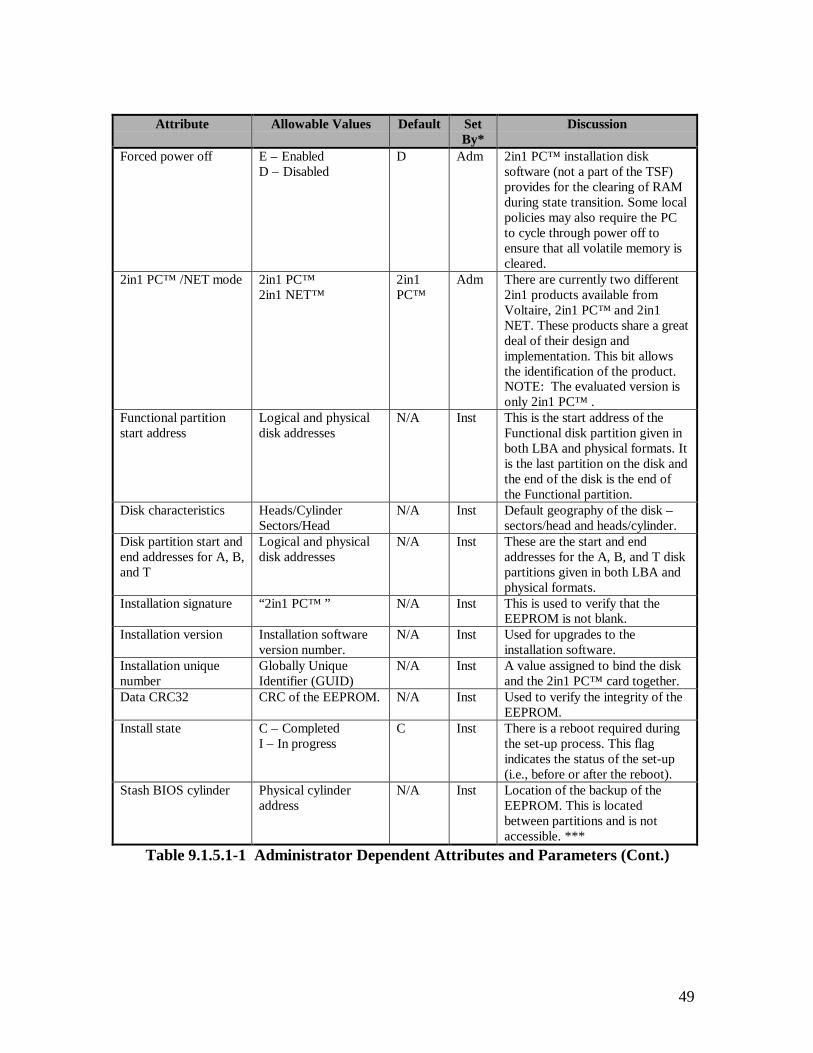
49
Attribute Allowable Values Default SetBy*
Discussion
Forced power off E – EnabledD – Disabled
D Adm 2in1 PC™ installation disksoftware (not a part of the TSF)provides for the clearing of RAMduring state transition. Some localpolicies may also require the PCto cycle through power off toensure that all volatile memory iscleared.
2in1 PC™ /NET mode 2in1 PC™2in1 NET™
2in1PC™
Adm There are currently two different2in1 products available fromVoltaire, 2in1 PC™ and 2in1NET. These products share a greatdeal of their design andimplementation. This bit allowsthe identification of the product.NOTE: The evaluated version isonly 2in1 PC™ .
Functional partitionstart address
Logical and physicaldisk addresses
N/A Inst This is the start address of theFunctional disk partition given inboth LBA and physical formats. Itis the last partition on the disk andthe end of the disk is the end ofthe Functional partition.
Disk characteristics Heads/CylinderSectors/Head
N/A Inst Default geography of the disk –sectors/head and heads/cylinder.
Disk partition start andend addresses for A, B,and T
Logical and physicaldisk addresses
N/A Inst These are the start and endaddresses for the A, B, and T diskpartitions given in both LBA andphysical formats.
Installation signature “2in1 PC™ ” N/A Inst This is used to verify that theEEPROM is not blank.
Installation version Installation softwareversion number.
N/A Inst Used for upgrades to theinstallation software.
Installation uniquenumber
Globally UniqueIdentifier (GUID)
N/A Inst A value assigned to bind the diskand the 2in1 PC™ card together.
Data CRC32 CRC of the EEPROM. N/A Inst Used to verify the integrity of theEEPROM.
Install state C – CompletedI – In progress
C Inst There is a reboot required duringthe set-up process. This flagindicates the status of the set-up(i.e., before or after the reboot).
Stash BIOS cylinder Physical cylinderaddress
N/A Inst Location of the backup of theEEPROM. This is locatedbetween partitions and is notaccessible. ***
Table 9.1.5.1-1 Administrator Dependent Attributes and Parameters (Cont.)

50
Attribute Allowable Values Default SetBy*
Discussion
MBRs for A, B, and T Boot loader andsystem tables
N/A Inst These are the actual MBR to beused for booting from the A, B,and T disk partitions.
* Adm means specifically set by the administrator. Inst means the value is determined by the set-upsoftware, depending on administrator selected parameters.** Ta and Tb are the Transition state where the next state has been identified as A or B, respectively.*** The stash is a mirror image of the EEPROM that is saved to facilitate recovery from a damaged ormalfunctioning 2in1 PC card. It has no security function. Without this information, much of the data onthe hard disk would be difficult to recover and my be completely lost, in the event of a failure. The stashresides in a gap between partitions, and therefore is never accessible in WORK mode (when you're inpartition A it is above your highest accessible sector, when you're in T and B, it's below your lowestaccessible sector). The "Stash BIOS cylinder" item in the EEPROM is the address of the cylinder in whichthe stash is located. It's used to assist in locating the stash when it needs to be updated (and not having tosequentially search the entire disk for it - a lengthy process).
Table 9.1.5.1-1 Administrator Dependent Attributes and Parameters (Cont.)
9.1.5.2 Dependencies
9.1.5.2.1 FDP_ACC.1 Subset Access Control
The TSF meets the requirement for this condition by providing subset access control.(See Section 9.1.1.)
9.1.5.2.2 FMT_SMR.1 Security Roles
The TSF meets the requirement for this condition by providing security roles. (SeeSection 9.1.7.)
9.1.6 FMT_MSA.3 Static Attribute Initialisation
Static attribute Initialisation ensures that the default values of security attributes areappropriately either permissive or restrictive in nature.
9.1.6.1 FMT_MSA.3.1
The TSF provides two different types of default access policies for the Functionalpartition, if one exists. For the Transition state, the defaults are restrictive. For states Aand B, the default is for a “read down” access policy, where state B may read and write tothe Functional partition and state A may only read from the Functional partition. Table9.1.6.1-1 shows the access rule attributes that have selectable values, the possibleselections, and the default selection.

51
Attribute Allowable Selections Default SelectionFirst power on state States A, B, T (where the next state is B), or T
(where the next state is A). (Note – Installationsoftware allows only Ta or Tb.)
State T (where the nextstate is A)
Access to the F diskpartition from state T
No access, read only access, or read/write access No access
Access to the T partitionfrom state T
Read only or read/write Read only
Access to the F partitionfrom state B
No access, read only access, or read/write access R/W
Access to the F partitionfrom state A
No access, read only access, or read/write access R
Slave disk state State A or B State ATable 9.1.6.1-1 Administrator Selectable Partitioning Access Policy Security
Attributes
9.1.6.1.1 FMT_MSA.3.1 – Transition state
The TSF shall enforce the [Partitioning Access Policy] to provide [restrictive] defaultvalues for security attributes that are used to enforce the SFP.
This element was satisfied by the TSF. The SFP is enforced in the Transition state.Administrator selectable access rules for the Transition state default to the mostrestrictive case, as shown in the access security policy (see Section 3). From theTransition state, the T partition is read only and no other partitions are accessible.
9.1.6.1.2 FMT_MSA.3.1 – States A and B
The TSF shall enforce the [Partitioning Access Policy] to provide [read down] defaultvalues for security attributes that are used to enforce the SFP.
This element was satisfied by the TSF. The SFP is enforced in the Transition state.Administrator selectable access rules for states A and B default to a “read down” case, asshown in the access security policy (see Section 3). Where state A is assumed to be amore restrictive state than state B, state B may read and write to the Functional partitionand state A may only read from the Functional partition. This will allow the flow ofinformation from state B to state A, but not from A to B.
9.1.6.2 FMT_MSA.3.2
The TSF shall allow the [administrator] to specify alternative initial values to overridethe default values when an object or information is created.
This element was satisfied by the TSF. In set-up mode, write access is logically andphysically enabled to the EEPROM, and the administrator has the capability to specifyalternative initial values to override default values. Typically, the administrator usesutilities provided on the 2in1 PC™ installation disks to set initial values and/or overridedefault values in the EEPROM. These utilities are not a part of the TSF and are not
52
included in Section 7 Product Testing, because they were defined to be outside the scopeof the TSF. The area where these elements were evaluated was in Section 9.2.3ADO_IGS.1 - Installation, Generation, and Start-Up Procedures.
9.1.6.3 Dependencies
9.1.6.3.1 FMT_MSA.1 Management of Security Attributes
The TSF meets the requirement for this condition by management of security attributes.(See Section 9.1.5.)
9.1.6.3.2 FMT_SMR.1 Security Roles
The TSF meets the requirement for this condition by providing security roles. (SeeSection 9.1.7.)
9.1.7 FMT_SMR.1 Security Roles
FMT_SMR.1 Security roles specifies the roles with respect to security that the TSFrecognises.
9.1.7.1 FMT_SMR.1.1
The TSF shall maintain the roles [administrator and user].
This element was satisfied by the TSF. There are two roles recognised by the 2in1 PC™TSF, the user role and the administrator role. There are specific actions that may onlyoccur in one or the other of the recognised roles.
9.1.7.2 FMT_SMR.1.2
The TSF shall be able to associate users with roles.
This element was satisfied by the TSF. All users operating the TOE in work mode are inthe user role. Anyone operating the TOE in set-up mode is considered to be in theadministrator role.
9.1.7.3 Dependencies
9.1.7.3.1 FIA_UID.1 Timing of Identification
The TSF meets the requirement for this condition by providing user identification beforeany action (See Section 9.1.4.). Administrators are required to be in set-up mode beforethey can perform any administrator functions. Being in work mode (i.e., the set-up plugnot being inserted on the 2in1 PC™ card) identifies the user role.
53
9.1.8 FMT_SMR.3 Assuming Roles
Assuming roles requires that an explicit request be given to the TSF to assume a role.
9.1.8.1 FMT_SMR.3.1
The TSF shall require an explicit request to assume the following roles: [administrator].
This element was satisfied by the TSF. Installation of the set-up plug in the TSF, andpower up in set-up mode, is the explicit action necessary to assume the administrator role.Anyone operating the TOE without being in set-up mode is considered to be a user.
A user may become an administrator by powering off the PC, opening the PC case,inserting the set-up plug on the 2in1 PC™ card, and turning the machine back on.Alternately, if the optional, internal enabler plug is already inserted on the 2in1 PC™card, the user need only turn the PC off, insert the external set-up jack, and turn thepower back on. To become a user again, the administrator reverses the process, removingthe set-up plug and restarting the machine in work mode. The TSF checks for thepresence of the set-up plug (in one of its two forms), thus identifying the user role, beforeperforming any functions on behalf of the user.
9.1.8.2 Dependencies
9.1.8.2.1 FMT_SMR.1 Security Roles
The TOE meets the requirement for this condition by providing security roles (SeeSection 9.1.7.).
9.1.9 FPT_FLS.1 Failure with Preservation of Secure State
FPT_FLS.1 Failure with preservation of secure state requires that the TSF preserve asecure state in the face of the identified failures.
9.1.9.1 FPT_FLS.1.1
The TSF shall preserve a secure state when the following types of failures occur: [forcedshutdown, power failure, or system failure].
This element was satisfied by the TSF. Under forced shutdown, power failure, or systemfailure in work mode, the TSF does not respond until it has reached the Transition state.The Transition state is defined in the 2in1 PC™ Informal Security Policy Model as beinga secure state. It allows no network connections, no access to either the A or B diskpartitions, read only access to the Transition disk partition, and access only to otherconnected devices that are connected through the !A (not A) or !B (not B) jumper pins.
54
9.1.9.2 Dependencies
9.1.9.2.1 ADV_SPM.1 Informal TOE Security Policy Model
The TOE meets the requirement for this condition by providing an informal TOE securitypolicy model (ref. Section 3). Upon failure in the work mode, the TSF always transitionsto, or through, the Transition state, described in the informal TOE security policy model.
9.1.10 FPT_RCV.4 Function Recovery
Function recovery, provides for recovery at the level of particular SFs, ensuring eithersuccessful completion or rollback of TSF data to a secure state.
9.1.10.1 FPT_RCV.4.1
The TSF shall ensure that [forced shutdown, power failure, or system failure while inwork mode] have the property that the SF either completes successfully, or for theindicated failure scenarios, recovers to a consistent and secure state.
This element was satisfied by the TSF. In work mode, the TSF recovers to, or through,the Transition state after any forced shutdown, power failure, or system failure. TheTransition state is defined in the 2in1 PC™ Informal Security Policy Model as being asecure state. It allows no network connections, no access to either the A or B diskpartitions, read only access to the Transition disk partition, and access only to otherconnected devices that are connected through the !A (not A) or !B (not B) jumper pins.
9.1.10.2 Dependencies
9.1.10.2.1 ADV_SPM.1 Informal TOE Security Policy Model
The TOE meets the requirement for this condition by providing an informal TOE securitypolicy model. (See Section 3.) Upon failure in the work mode, the TSF always transitionsto, or through, the secure (i.e., transition) state, described in the informal TOE securitypolicy model.
9.1.11 FPT_RVM.1 Non-Bypassability of the TSP
FPT_RVM.1 requires non-bypassability for all SFPs in the TSP.
9.1.11.1 FPT_RVM.1.1
The TSF shall ensure that TSP enforcement functions are invoked and succeed beforeeach function within the TSC is allowed to proceed.
55
This element was satisfied by the TSF. In work mode, there are four user visiblefunctions that the TSF controls. They are:
1. Read or write access to disk partitions,
2. Connectivity to network connections,
3. Connectivity to other (optional) TSF controlled devices, and
4. Switch user states.
The TSF controls each of these functions and allows them to proceed only if they complywith the Partitioning Access Policy. Additionally, the user state switch may occur only ifit does not violate the Floppy Disk Switching Policy.
9.1.11.2 Dependencies
This requirement has no dependencies.
9.1.12 FPT_SEP.3 Complete Reference Monitor
Complete reference monitor, requires that there be distinct domain(s) for TSPenforcement, a domain for the remainder of the TSF, as well as domains for the non-TSFportions of the TOE.
9.1.12.1 FPT_SEP.3.1
The unisolated portion of the TSF shall maintain a security domain for its own executionthat protects it from interference and tampering by untrusted subjects.
This element was satisfied by the TSF. The TOE security policy is enforced entirely bythe 2in1 PC™ card. The TSF is isolated from interference or modification. The statemachine implementation is in the Altera chip that is loaded from ROM and is notaccessible by untrusted subjects. The EEPROM is not writeable without the set-up plug,and therefore not writeable by untrusted subjects. The IDE checking is also implementedin the Altera chip that is loaded from ROM, and its security attributes are on theEEPROM. The Altera chip has no input interface open to outside of the TSF.
9.1.12.2 FPT_SEP.3.2
The TSF shall enforce separation between the security domains of subjects in the TSC.
This element was satisfied by the TSF. The user security domains are maintained by acombination of the security features implemented on the 2in1 PC™ card. ThePartitioning Access Policy is intended to contain a user session to an authorisedenvironment that includes a network connection, disk partition(s), and other local

56
interfaces, depending on the local organisation security policy and the administratorcontrolled settings. Each user state has it’s own domain that includes disk partitions,network connections, and other device connections. Separation of these domains isprovided by the TSF.
9.1.12.3 FPT_SEP.3.3
The TSF shall maintain the part of the TSF that enforces the access controland/or information flow control SFPs in a security domain for its ownexecution that protects them from interference and tampering by theremainder of the TSF and by subjects untrusted with respect to the TSP.
This element was satisfied by the TSF. The access control SFPs covered in thisrequirement are the Partitioning Access Policy and the Administrator Access Policy.There are no information flow control policies for this TOE. The TOE security policy isenforced entirely by the 2in1 PC™ card. The card is isolated from interference ormodification. The state machine, IDE checking, and network and other hardwareinterface access control implementation is in the Altera chip that is loaded from ROM.The Altera chip has no input interface open to outside of the TSF. Object securityattributes are on the EEPROM and are not writeable without the set-up plug, andtherefore not writeable by untrusted subjects.
9.1.12.4 Dependencies
This requirement has no dependencies.
9.2 ASSURANCE REQUIREMENTS
The assurance requirements for the TOE are the EAL2 assurance requirements,augmented by the informal TOE security policy model requirement. Table 9.2-1 lists theassurance requirements from the 2in1 PC™ Security Target Report.
Assurance Requirement DescriptionACM_CAP.2 Configuration ItemsADO_DEL.1 Delivery ProceduresADO_IGS.1 Installation, Generation, and Start-Up ProceduresADV_FSP.1 Informal Functional SpecificationADV_HLD.1 Descriptive High-Level DesignADV_RCR.1 Informal Correspondence DemonstrationADV_SPM.1 Informal TOE Security Policy ModelAGD_ADM.1 Administrator GuidanceAGD_USR.1 User GuidanceATE_COV.1 Evidence of CoverageATE_FUN.1 Functional TestingATE_IND.2 Independent Testing – SampleAVA_SOF.1 Strength of TOE Security Function EvaluationAVA_VLA.1 Developer Vulnerability Analysis
Table 9.2-1 Assurance Requirements
57
9.2.1 ACM_CAP.2 Configuration Items
9.2.1.1 Evidence Elements
This section addresses the individual content and presentation evidence elements asdefined in the CC Version 2, May 1998. Specifically, these elements consist of theunique identification and description of the TOE configuration items. These uniquelyidentified configuration items provide a definition of the TOE hardware and softwareelements that lead to an overall unique version number for the TOE. Furthermore, theconfiguration management system used in the assignment of the identification ofhardware items, software items, and the TOE itself is also provided.
9.2.1.2 Evaluator Action Elements and Findings
9.2.1.2.1 Unique Version Numbers
The 2in1 PC™ Configuration Items satisfies this element by defining a unique versionfor the TOE. The version defined for the TOE is 1.21. The 2in1 PC™ ConfigurationItems further defines the TOE contents, software elements and card componentsidentifying the manufacturer version numbers and in some cases, the reassigned versionnumbers by the vendor.
9.2.1.2.2 Labeled With Reference
The 2in1 PC™ Configuration Items satisfies this element by listing labeled versionnumbers for the TOE such that the consumer can identify the TOE at the point ofpurchase. Verification that these procedures are in place and that the configuration itemversion numbers match the evaluated TOE was performed in Section 9.2.2.2.1,Description of Delivery Procedures.
9.2.1.2.3 Configuration List
The 2in1 PC™ Configuration Items satisfies this element by providing a list of theunique version numbers for the container items of the TOE. The container items definethe unique version numbers assigned by the vendor to the contents of the TOE as follows:
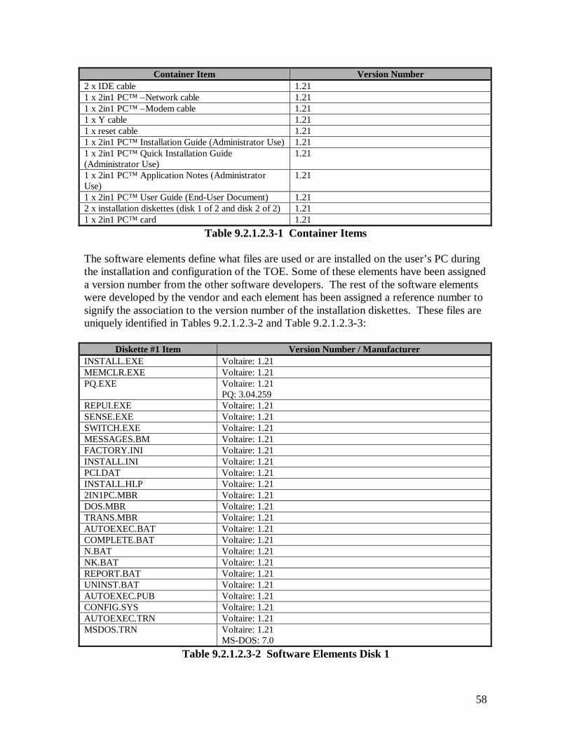
58
Container Item Version Number2 x IDE cable 1.211 x 2in1 PC™ –Network cable 1.211 x 2in1 PC™ –Modem cable 1.211 x Y cable 1.211 x reset cable 1.211 x 2in1 PC™ Installation Guide (Administrator Use) 1.211 x 2in1 PC™ Quick Installation Guide(Administrator Use)
1.21
1 x 2in1 PC™ Application Notes (AdministratorUse)
1.21
1 x 2in1 PC™ User Guide (End-User Document) 1.212 x installation diskettes (disk 1 of 2 and disk 2 of 2) 1.211 x 2in1 PC™ card 1.21
Table 9.2.1.2.3-1 Container Items
The software elements define what files are used or are installed on the user’s PC duringthe installation and configuration of the TOE. Some of these elements have been assigneda version number from the other software developers. The rest of the software elementswere developed by the vendor and each element has been assigned a reference number tosignify the association to the version number of the installation diskettes. These files areuniquely identified in Tables 9.2.1.2.3-2 and Table 9.2.1.2.3-3:
Diskette #1 Item Version Number / ManufacturerINSTALL.EXE Voltaire: 1.21MEMCLR.EXE Voltaire: 1.21PQ.EXE Voltaire: 1.21
PQ: 3.04.259REPUI.EXE Voltaire: 1.21SENSE.EXE Voltaire: 1.21SWITCH.EXE Voltaire: 1.21MESSAGES.BM Voltaire: 1.21FACTORY.INI Voltaire: 1.21INSTALL.INI Voltaire: 1.21PCI.DAT Voltaire: 1.21INSTALL.HLP Voltaire: 1.212IN1PC.MBR Voltaire: 1.21DOS.MBR Voltaire: 1.21TRANS.MBR Voltaire: 1.21AUTOEXEC.BAT Voltaire: 1.21COMPLETE.BAT Voltaire: 1.21N.BAT Voltaire: 1.21NK.BAT Voltaire: 1.21REPORT.BAT Voltaire: 1.21UNINST.BAT Voltaire: 1.21AUTOEXEC.PUB Voltaire: 1.21CONFIG.SYS Voltaire: 1.21AUTOEXEC.TRN Voltaire: 1.21MSDOS.TRN Voltaire: 1.21
MS-DOS: 7.0Table 9.2.1.2.3-2 Software Elements Disk 1

59
Diskette #1 Item Version Number / ManufacturerCOMMAND.COM MS-DOS: 7.0IO.SYS MS-DOS: 7.0ATTRIB.EXE MS-DOS: 7.0CHOICE.COM MS-DOS: 7.0MORE.COM MS-DOS: 7.0MOUSE.COM MS-DOS: 7.0SYS.COM MS-DOS: 7.0MSDOS.SYS MS-DOS: 7.0RAMDRIVE.SYS MS-DOS: 7.0HIMEM.SYS MS-DOS: 7.0
Table 9.2.1.2.3-2 Software Elements Disk 1 (Cont.)
Diskette #2 Item Version Number / Manufacturer\DOS\2IN1TSR3.COM Voltaire: 1.21\DOS\INSTALL.COM Voltaire: 1.21\DOS\TSR.DAT Voltaire: 1.21\OS2\AUTOEXEC.BAT Voltaire: 1.21\OS2\INSTALL.BAT Voltaire: 1.21\UNIX\LINUX\README.TXT Voltaire: 1.21\UNIX\LINUX\ V2IN1DRV-0.39.TAR.GZ
Voltaire: 1.21
\UNIX\LINUX\ V2IN1DRV-0.39-LINUX.BIN.TAR.GZ
Voltaire: 1.21
\UNIX\SCO\README Voltaire: 1.21\UNIX\SCO\V2I1SCO.TAR Voltaire: 1.21UNIX\SCO\V2IN1DRV-0.39-SCO.BIN.TAR.GZ
Voltaire: 1.21
\UTILS\APM.EXE Voltaire: 1.21\UTILS\CONFIG.PSW Voltaire: 1.21\UTILS\ENCRYPT.EXE Voltaire: 1.21\UTILS\PASSWORD.SYS Voltaire: 1.21\UTILS\PSW.BAT Voltaire: 1.21\UTILS\FILE2E2.EXE Voltaire: 1.21\UTILS\RE2.EXE Voltaire: 1.21\UTILS\RWE2.EXE Voltaire: 1.21\WIN\SETUP.EXE Voltaire: 1.21DEBUG.EXE MS-DOS: 7.0EDIT.COM MS-DOS: 7.0FORMAT.COM MS-DOS: 7.0MORE.COM MS-DOS: 7.0
Table 9.2.1.2.3-3 Software Elements Disk 2
The card components define the low-level components the TOE is comprised of. Thesecomponents are assigned unique version numbers from the manufacturer and in somecases, the vendor has reassigned the numbers as follows:

60
Card Component Version Number / Manufacturer1 x PCB Voltaire: Rev. B1 x EEPROM chip ATMEL: AT28C16-15SC or
Xicor: X2816CS-15Voltaire: 1.21
1 x PROM chip Altera: EPC1441 LC20Voltaire: 12A
6 x Electro-mechanical relays NaiS: TQ2SA-5V1 x Internal Set-up plug None1 x Altera chip Altera Flex EPF6016TC144-32 x IDE connectors None4 x Network connectors None6 x Floppy disconnection jumpers None
Table 9.2.1.2.3-4 Card Components
9.2.1.2.4 Description of Configuration Items that Comprise the TOE
The 2in1 PC™ Configuration Items satisfies this element by providing a description ofeach configuration item the TOE is comprised of. These items are defined as follows:
Container Item Version Number Description2 x IDE cable 1.21 Used to connect the hard disk(s) to the
2in1 PC™ card, and the 2in1 PC™ card tothe IDE controller.
1 x 2in1 PC™ –Network cable 1.21 Used to connect one 2in1 PC™ networkconnector to a network interface card.
1 x 2in1 PC™ –Modem cable 1.21 Used to connect one 2in1 PC™ networkconnector to a modem.
1 x Y cable 1.21 Used to connect both 2in1 PC™ networkconnectors to one NIC.
1 x reset cable 1.21 Used to connect the 2in1 PC™ card to themotherboard’s reset pins (necessary onlywith certain platforms).
1 x 2in1 PC™ Installation Guide(Administrator Use)
1.21 Provide detailed installation andadministration instructions for theinstaller/administrator.
1 x 2in1 PC™ Quick InstallationGuide (Administrator Use)
1.21 Provide quick and simple installationreference for the installer/administrator.
1 x 2in1 PC™ Application Notes(Administrator Use)
1.21 Provide information to theinstaller/administrator about specialproblematic hardware platforms, andtroubleshooting.
1 x 2in1 PC™ User Guide (End-User Document)
1.21 Provide operating instructions for the enduser.
2 x installation diskettes (disk 1of 2 and disk 2 of 2)
1.21 Used to configure the PC on which the2in1 PC™ is installed.
1 x 2in1 PC™ card 1.21 (See Table 9.2.1.2.4-4)Table 9.2.1.2.4-1 Container Items
The software elements define what files are used or installed on the user’s PC during theinstallation and configuration of the TOE. Some of these elements have been assigned aversion number from the other software developers. The rest of the software elements

61
were developed by the vendor and each element has been assigned a reference number tosignify the association to the version number of the installation diskettes. These files aredescribed in Table 9.2.1.2.4-2 and Table 9.2.1.2.4-2 as follows:
Diskette #1 Item Version Number /Manufacturer
Description
INSTALL.EXE Voltaire: 1.21 2in1 PC™ installation programMEMCLR.EXE Voltaire: 1.21 RAM clearing utility, copied to T partition.PQ.EXE Voltaire: 1.21
PQ: 3.04.259PowerQuest Partition Magic disk partitioning utility(compressed)
Table 9.2.1.2.4-2 Software Elements Disk 1
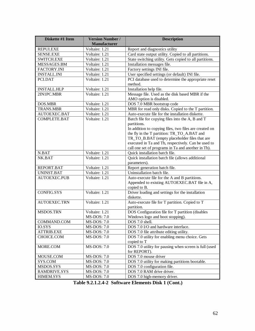
62
Diskette #1 Item Version Number /Manufacturer
Description
REPUI.EXE Voltaire: 1.21 Report and diagnostics utilitySENSE.EXE Voltaire: 1.21 Card state output utility. Copied to all partitions.SWITCH.EXE Voltaire: 1.21 State switching utility. Gets copied to all partitions.MESSAGES.BM Voltaire: 1.21 Installation messages file.FACTORY.INI Voltaire: 1.21 Factory settings INI file.INSTALL.INI Voltaire: 1.21 User specified settings (or default) INI file.PCI.DAT Voltaire: 1.21 PCI database used to determine the appropriate reset
method.INSTALL.HLP Voltaire: 1.21 Installation help file.2IN1PC.MBR Voltaire: 1.21 Message file. Used as the disk based MBR if the
AMO option is disabled.DOS.MBR Voltaire: 1.21 DOS 7.0 MBR bootstrap codeTRANS.MBR Voltaire: 1.21 MBR for read only disks. Copied to the T partition.AUTOEXEC.BAT Voltaire: 1.21 Auto-execute file for the installation diskette.COMPLETE.BAT Voltaire: 1.21 Batch file for copying files into the A, B and T
partitions.In addition to copying files, two files are created onthe fly in the T partition: TR_TO_A.BAT andTR_TO_B.BAT (empty placeholder files that areexecuted in Ta and Tb, respectively. Can be used tocall one set of programs in Ta and another in Tb).
N.BAT Voltaire: 1.21 Quick installation batch file.NK.BAT Voltaire: 1.21 Quick installation batch file (allows additional
parameters).REPORT.BAT Voltaire: 1.21 Report generation batch file.UNINST.BAT Voltaire: 1.21 Uninstallation batch file.AUTOEXEC.PUB Voltaire: 1.21 Auto-execute file for the A and B partitions.
Appended to existing AUTOEXEC.BAT file in A,copied to B.
CONFIG.SYS Voltaire: 1.21 Driver loading and settings for the installationdiskette.
AUTOEXEC.TRN Voltaire: 1.21 Auto-execute file for T partition. Copied to Tpartition.
MSDOS.TRN Voltaire: 1.21MS-DOS: 7.0
DOS Configuration file for T partition (disablesWindows logo and boot stopping).
COMMAND.COM MS-DOS: 7.0 DOS 7.0 shell.IO.SYS MS-DOS: 7.0 DOS 7.0 I/O and hardware interface.ATTRIB.EXE MS-DOS: 7.0 DOS 7.0 file attribute editing utility.CHOICE.COM MS-DOS: 7.0 DOS 7.0 utility for enabling menu choice. Gets
copied to TMORE.COM MS-DOS: 7.0 DOS 7.0 utility for pausing when screen is full (used
for REPORT).MOUSE.COM MS-DOS: 7.0 DOS 7.0 mouse driverSYS.COM MS-DOS: 7.0 DOS 7.0 utility for making partitions bootable.MSDOS.SYS MS-DOS: 7.0 DOS 7.0 configuration file.RAMDRIVE.SYS MS-DOS: 7.0 DOS 7.0 RAM drive driver.HIMEM.SYS MS-DOS: 7.0 DOS 7.0 high-memory driver.
Table 9.2.1.2.4-2 Software Elements Disk 1 (Cont.)
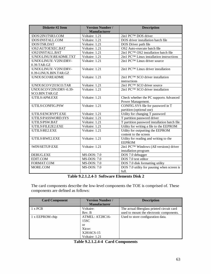
63
Diskette #2 Item Version Number /Manufacturer
Description
\DOS\2IN1TSR3.COM Voltaire: 1.21 2in1 PC™ DOS driver\DOS\INSTALL.COM Voltaire: 1.21 DOS driver installation batch file\DOS\TSR.DAT Voltaire: 1.21 DOS Driver path file\OS2\AUTOEXEC.BAT Voltaire: 1.21 OS2 Auto-execute batch file\OS2\INSTALL.BAT Voltaire: 1.21 2in1 PC™ OS2 installation batch file\UNIX\LINUX\README.TXT Voltaire: 1.21 2in1 PC™ Linux installation instructions\UNIX\LINUX\ V2IN1DRV-0.39.TAR.GZ
Voltaire: 1.21 2in1 PC™ Linux driver source
\UNIX\LINUX\ V2IN1DRV-0.39-LINUX.BIN.TAR.GZ
Voltaire: 1.21 2in1 PC™ Linux driver installation
\UNIX\SCO\README Voltaire: 1.21 2in1 PC™ SCO driver installationinstructions
\UNIX\SCO\V2I1SCO.TAR Voltaire: 1.21 2in1 PC™ SCO driver sourceUNIX\SCO\V2IN1DRV-0.39-SCO.BIN.TAR.GZ
Voltaire: 1.21 2in1 PC™ SCO driver installation
\UTILS\APM.EXE Voltaire: 1.21 Check whether the PC supports AdvancedPower Management.
\UTILS\CONFIG.PSW Voltaire: 1.21 CONFIG.SYS file for password in Tpartition (optional use)
\UTILS\ENCRYPT.EXE Voltaire: 1.21 Utility for changing T password\UTILS\PASSWORD.SYS Voltaire: 1.21 T partition password driver\UTILS\PSW.BAT Voltaire: 1.21 T partition password installation batch file\UTILS\FILE2E2.EXE Voltaire: 1.21 Utility for writing a file to the EEPROM\UTILS\RE2.EXE Voltaire: 1.21 Utility for outputting the EEPROM
content to the screen\UTILS\RWE2.EXE Voltaire: 1.21 Utility for reading and writing to the
EEPROM\WIN\SETUP.EXE Voltaire: 1.21 2in1 PC™ Windows (All versions) driver
installation programDEBUG.EXE MS-DOS: 7.0 DOS 7.0 debuggerEDIT.COM MS-DOS: 7.0 DOS 7.0 text editorFORMAT.COM MS-DOS: 7.0 DOS 7.0 disk formatting utilityMORE.COM MS-DOS: 7.0 DOS 7.0 utility for pausing when screen is
full.Table 9.2.1.2.4-3 Software Elements Disk 2
The card components describe the low-level components the TOE is comprised of. Thesecomponents are defined as follows:
Card Component Version Number /Manufacturer
Description
1 x PCB Voltaire:Rev. B
The actual fiberglass printed circuit cardused to mount the electronic components.
1 x EEPROM chip ATMEL: AT28C16-15SCorXicor:X2816CS-15Voltaire: 1.21
Used to store configuration data.
Table 9.2.1.2.4-4 Card Components

64
Card Component Version Number /Manufacturer
Description
1 x PROM chip Altera:EPC1441 LC20Voltaire: 12A
Used to store the code that operates the2in1 PC™ card.
6 x Electro-mechanical relays NaiS:TQ2SA-5V
Used to sever network and telephonewires connected to the 2in1 PC™ card.
1 x Internal Set-up plug None Used to Enable EEPROM alteration andfull disk access.
1 x Altera chip Altera FlexEPF6016TC144-3
Used to perform processing and logicoperations.
2 x IDE connectors None Used to route the IDE cables through the2in1 PC™ card.
4 x Network connectors None Used to route the network/telephonecables through the 2in1 PC™ card.
6 x Floppy disconnection jumpers None Used to provide the ability to severperipheral devices’ cables.
Table 9.2.1.2.4-4 Card Components (Cont.)
9.2.1.2.5 Method of Unique Identification of Configuration Items
The 2in1 PC™ Configuration Items satisfies this element by defining a unique method ofidentification. Both the installation diskettes and the 2in1 PC™ card are clearly markedas version 1.21. The following is a list of the uniquely identified TOE elements:
Container Item VersionNumber
Description
2 x installationdiskettes (disk 1 of 2and disk 2 of 2)
1.21 Voltaire’s version number is incremented by 0.01 every time aminor change, such as a bug fix, is implemented. Incrementedby 0.1 when a major change, such as new logic design isimplemented.
1 x 2in1 PC™ card 1.21 Voltaire’s version number is incremented by 0.01 every time aminor change, such as a bug fix, is implemented. It isincremented by 0.1 when a major change, such as new logicdesign or card architecture is implemented.
Table 9.2.1.2.4-1 Container Items
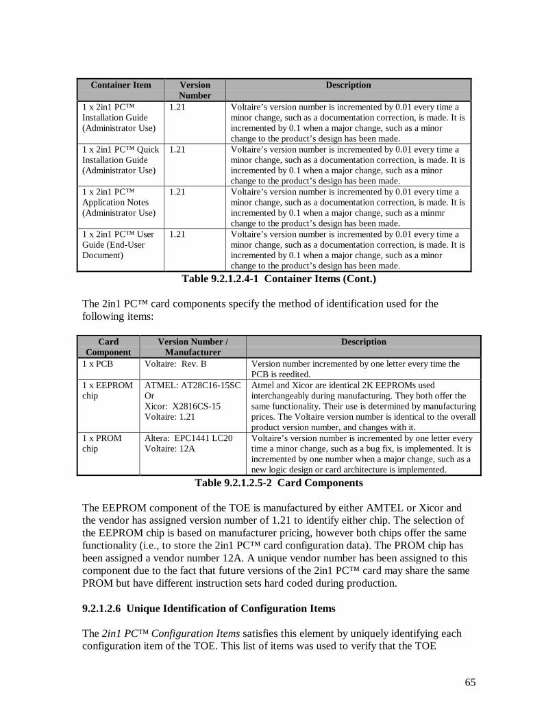
65
Container Item VersionNumber
Description
1 x 2in1 PC™Installation Guide(Administrator Use)
1.21 Voltaire’s version number is incremented by 0.01 every time aminor change, such as a documentation correction, is made. It isincremented by 0.1 when a major change, such as a minorchange to the product’s design has been made.
1 x 2in1 PC™ QuickInstallation Guide(Administrator Use)
1.21 Voltaire’s version number is incremented by 0.01 every time aminor change, such as a documentation correction, is made. It isincremented by 0.1 when a major change, such as a minorchange to the product’s design has been made.
1 x 2in1 PC™Application Notes(Administrator Use)
1.21 Voltaire’s version number is incremented by 0.01 every time aminor change, such as a documentation correction, is made. It isincremented by 0.1 when a major change, such as a minmrchange to the product’s design has been made.
1 x 2in1 PC™ UserGuide (End-UserDocument)
1.21 Voltaire’s version number is incremented by 0.01 every time aminor change, such as a documentation correction, is made. It isincremented by 0.1 when a major change, such as a minorchange to the product’s design has been made.
Table 9.2.1.2.4-1 Container Items (Cont.)
The 2in1 PC™ card components specify the method of identification used for thefollowing items:
CardComponent
Version Number /Manufacturer
Description
1 x PCB Voltaire: Rev. B Version number incremented by one letter every time thePCB is reedited.
1 x EEPROMchip
ATMEL: AT28C16-15SCOrXicor: X2816CS-15Voltaire: 1.21
Atmel and Xicor are identical 2K EEPROMs usedinterchangeably during manufacturing. They both offer thesame functionality. Their use is determined by manufacturingprices. The Voltaire version number is identical to the overallproduct version number, and changes with it.
1 x PROMchip
Altera: EPC1441 LC20Voltaire: 12A
Voltaire’s version number is incremented by one letter everytime a minor change, such as a bug fix, is implemented. It isincremented by one number when a major change, such as anew logic design or card architecture is implemented.
Table 9.2.1.2.5-2 Card Components
The EEPROM component of the TOE is manufactured by either AMTEL or Xicor andthe vendor has assigned version number of 1.21 to identify either chip. The selection ofthe EEPROM chip is based on manufacturer pricing, however both chips offer the samefunctionality (i.e., to store the 2in1 PC™ card configuration data). The PROM chip hasbeen assigned a vendor number 12A. A unique vendor number has been assigned to thiscomponent due to the fact that future versions of the 2in1 PC™ card may share the samePROM but have different instruction sets hard coded during production.
9.2.1.2.6 Unique Identification of Configuration Items
The 2in1 PC™ Configuration Items satisfies this element by uniquely identifying eachconfiguration item of the TOE. This list of items was used to verify that the TOE
66
delivered in Section 9.2.2 ADO_DEL.1 Delivery Procedures was properly marked withthe specified manufacturer and vendor version numbers.
9.2.1.2.7 Configuration Items Evidence
The following vendor documentation was referenced to satisfy this assurance component.• E21198041(4), 2in1 PC™ Configuration Items
9.2.2 ADO_DEL.1 Delivery Procedures
9.2.2.1 Evidence Elements
This section addresses the vendor delivery procedures when delivering the TOE to theuser’s location. The system controls and distribution facility procedures are defined toprovide assurance that the recipient receives the TOE without any modifications. Theestablished procedures define the steps the developer is enforcing to guarantee that therecipient receives the version that corresponds precisely to the TOE master copy, thusavoiding any tampering with the actual version, or substitution of a false version.
9.2.2.2 Evaluator Action Elements and Findings
9.2.2.2.1 Description of Delivery Procedures
The delivery procedures implemented by Voltaire satisfy this element by defining thesteps for the secure delivery of the TOE to the user’s site. The specific steps followed byVoltaire are:
1. Every 2in1 PC™ card undergoes a full final test before being packaged andshipped. This test ensures that the card is in working order (functionality-wise andsecurity-wise), ensures that the PROM version and the software on the installationdiskette are correct. (See 2in1 PC™ Product Approval Tests for furtherinformation regarding this procedure).
2. A sticker with the product’s overall version number is placed on the card itself.
3. Every TOE package is individually sealed using a sticker displaying the Voltairelogo, thereby preventing the possibility of opening the box and tampering with itscontents without being noticed.
4. A sticker with the product’s overall version number is placed on the package.
5. The TOE is stored in a controlled environment prior to shipment, i.e., a guardedoffice building, inside a locked office protected by an alarm system.
6. Cards are shipped to their final destination either by courier or by public mail.
67
After reviewing the vendor delivery procedure documentation, an order for the TOE wasplaced to verify that the documented delivery procedures were being enforced. Afterreceipt of the TOE, these delivery procedures were verified. This verification wasperformed in the following manner:
1. Physically inspecting the package upon receipt to confirm that the TOE wasproperly sealed.
2. Confirming that the TOE received matched the configuration items listed inSection 9.2.1.
Note: Version numbers on the card and package were not confirmed upon receiptof the TOE (items 2 and 4 of the vendor delivery procedures). This was due to thefact that when the order for the TOE was made, these procedures were notspecified. The requirement for these procedures was identified and has beenincorporated into Voltaire’s delivery procedures.
3. Installing and configuring the TOE to confirm that the 2in1 PC™ card operated asspecified. Section 9.2.12 defines the independent testing that was conducted andprovides details on the tests performed.
9.2.2.2.2 Delivery Procedures Evidence
The following vendor documentation was referenced to satisfy this assurance component.• E20598011, 2in1 PC™ Product Approval Tests• E21198045, 2in1 PC™ Delivery Procedure
9.2.3 ADO_IGS.1 Installation, Generation, and Start-Up Procedures
9.2.3.1 Evidence Elements
9.2.3.2 Evaluator Action Elements and Findings
This section addresses the installation, generation, and start-up procedures after receipt ofthe TOE from the vendor. These procedures provide assurance that the documentationprovided as part of the TOE is sufficient in detail to securely configure the TOE in itstarget environment.
9.2.3.2.1 Description of Installation, Generation, and Start-Up
Verification of the vendor’s installation, generation, and start-up procedures for the TOEsatisfies this element. These one-time procedures were verified using only the supportingdocumentation, the installation software, and other package contents that was provided
68
with the TOE in order to configure it to a secure operational state. Before theinstallation of the TOE commenced, the 2in1 PC Installation Guide was used to verifythat all of the TOE components have been received. Once this verification was made,Chapter 9 of the 2in1 PC Installation Guide was also examined. This Chapter addressesthe reconfiguration, reinstallation, or removal of the 2in1 PC™ card. For the specificevaluation details of the TOE documentation, please refer to the COACT, Inc. documententitled Evaluation of the 2in1 PC Installation Guide, Version 1.21. This documentdefines areas expressed to the vendor that should be included in future versions of theinstallation guide, however do not directly affect the procedures necessary for the secureinstallation, generation, and start-up of the TOE. When performing the installation,generation, and start-up procedures, the TOE provided a Graphical User Interface (GUI)so that the administrator could verify that the TOE security functions were properlyconfigured.
9.2.3.2.2 Determination of Resulting Configuration
Verification of the vendor-supplied installation, generation, and start-up proceduredocumentation has satisfied this element. This verification was performed by installingthe TOE using the included product documentation and by performing a trial run toconfirm that the TOE security functions were being enforced. Once the enforcement ofthe TOE security functions was verified, the security functions were further evaluatedthrough the replication of vendor tests and the execution of independent evaluator testsdefined in Section 9.2.12 ATE_IND.2, Independent Testing - Sample.
9.2.3.2.3 Installation, Generation, and Start-Up Evidence
The following vendor documentation was referenced to satisfy this assurance component.• E21298062, 2in1 PC™ App. Notes – Special Settings• E21298063, 2in1 PC™ Installation Guide• E21298064, 2in1 PC™ Quick Installation Guide• E21198039(2), Evaluation of the 2in1 PC™ Installation Guide, Version 1.21
9.2.4 ADV_FSP.1 Informal Functional Specification
9.2.4.1 Documentation Included in the Functional Specification
The following documents were considered part of the 2in1 PC™ functional specification:• E21198024, 2in1 PC™ System Design Document• E21298054, 2in1 PC™ Functional Specifications• E21198061, 2in1 PC™ Updates to the SYD EEPROM Mapping Section
9.2.4.2 Evidence Elements
This section addresses the informal functional specification that completely represents theTSF. The informal functional specification provides a high-level description of the user-visible interfaces and the behavior of the TSF. It is an instantiation of the TOE security
69
functional requirements. The functional specification shows that all the TOE securityfunctional requirements have been addressed.
9.2.4.3 Evaluator Action Elements and Findings
9.2.4.3.1 Description of the TSF and External Interfaces
The TOE satisfies this element. The TOE functional specification is in an informal style,written in English. All documents listed in Section 9.2.4.1 were considered in making thisdetermination.
9.2.4.3.2 Internally Consistent
The TOE satisfies this element. The functional specification is internally consistent. Itcontains no contradictory statements. The initial documentation, the 2in1 PC™ SystemDesign Document, is incomplete, sometimes vague, and has a few errors in it. Theseproblems have been corrected with supplemental documentation, including the 2in1PC™ Functional Specification and Updates to the SYD EEPROM Mapping Section. Thenew functional specification is consistent with the 2in1 PC™ System Design Document,but organises and defines the functions differently and adds more detail. The Updates tothe SYD EEPROM Mapping Section provide corrections to Appendix A – 2in1 PC™Configuration Summary in the 2in1 PC™ System Design Document. All documentslisted in Section 9.2.4.1 were considered in making this determination.
9.2.4.3.3 Purposes and Uses of External Interfaces
The TOE satisfies this element. The 2in1 PC™ Functional Specification providessufficient information on the purposes and uses of the interfaces to the TSF. Anexamination of the 2in1 PC™ card reveals the existence of the following physicalconnections:
1. ISA edge connector to the PC motherboard,
2. IDE bus connector to the PC motherboard (or the hard disk controller card, asappropriate),
3. IDE bus connector to the hard disk drive,
4. 2 RJ-45 network connector sockets,
5. 2 RJ-11 network connector sockets,
6. Set-up plug connector pins,
7. 26 jumper pins, and an
70
8. External set-up connector jack.
Additionally, there are 6 electro-mechanical relays that, while they are not externalinterfaces, provide the access control mechanism that enforces the security policy onsome of the external interfaces (see Sections 9.2.4.3.3.4 and 9.2.4.3.3.6).
The uses of each of these interfaces are described in the 2in1 PC™ FunctionalSpecification and are more fully explained in other supporting documentation (e.g., 2in1PC™ Installation Guide).
All of the TSFIs listed in the following sections can be derived, directly or indirectly,from the security functional requirements presented in Section 9.1. All interfacesmandated or implied in the security functional requirements are discussed in the 2in1PC™ Functional Specifications.
As described in the following sections, the available documentation identifies allinterfaces to the TSF and correctly and completely describes the behavior of the TOE ateach external interface. All security relevant input parameters, or a characterisation ofthose parameters, have been described. The following sections provide specificreferences to documentation, in addition to the 2in1 PC™ Functional Specification, thatwas used in determining the purpose and use of all of the external interfaces to the TSF.
9.2.4.3.3.1 ISA Bus
The ISA bus is used to receive reset signals and detect DMA2 activity. It is used in thefollowing security functions, as described in the 2in1 PC™ Functional Specification:
1. In work mode, control the flow of state changes (Function 7)
2. In work mode, monitor DMA2 activity during the Transition state and preventstate switching upon detection thereof (Function 9)
Detection of DMA2 activity affects the enforcement of the Floppy Disk Switching Policyin that the TSF will not allow any state switching if DMA2 activity has been detected inthe Transition state. This detection is performed by the DMA controller receiving DMA2activity from the ISA bus only. Since PCI devices do not interface with the DMAcontroller, their operation is not monitored by the TSF. This condition may only becleared by a reboot. (Ref. 2in1 PC™ System Design Document, Sections 3.1 & 4.2.2.)
The ISA bus reset signal is used as a part of state switching, but does not directly affectthe enforcement of the security policy. It indirectly affects the enforcement of thePartitioning Access Policy in that it can affect the machine state. However, the TSF willcontinue to enforce the Partitioning Access Policy for whatever state the machine is in.(Ref. 2in1 PC™ System Design Document, Sections 3.1, 3.4, 3.5 & 4.2.2.)
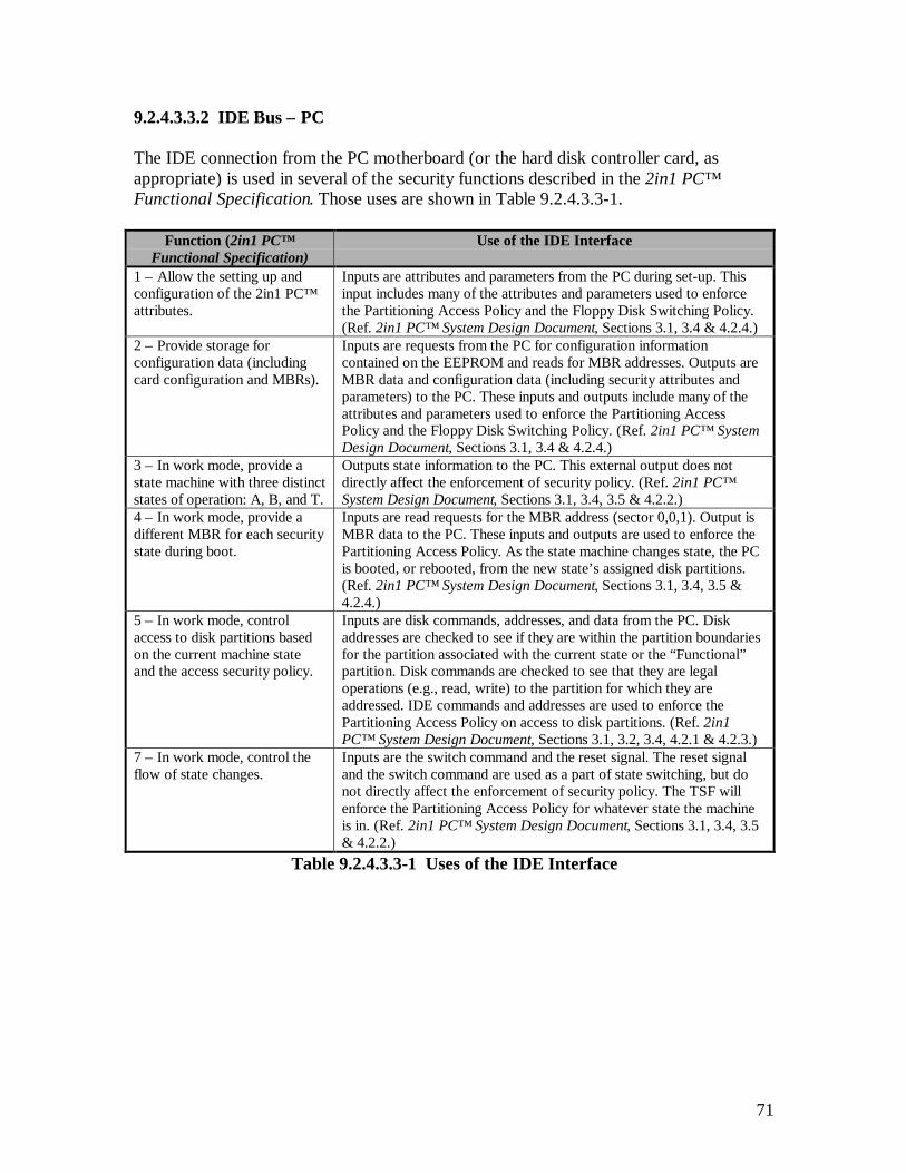
71
9.2.4.3.3.2 IDE Bus – PC
The IDE connection from the PC motherboard (or the hard disk controller card, asappropriate) is used in several of the security functions described in the 2in1 PC™Functional Specification. Those uses are shown in Table 9.2.4.3.3-1.
Function (2in1 PC™Functional Specification)
Use of the IDE Interface
1 – Allow the setting up andconfiguration of the 2in1 PC™attributes.
Inputs are attributes and parameters from the PC during set-up. Thisinput includes many of the attributes and parameters used to enforcethe Partitioning Access Policy and the Floppy Disk Switching Policy.(Ref. 2in1 PC™ System Design Document, Sections 3.1, 3.4 & 4.2.4.)
2 – Provide storage forconfiguration data (includingcard configuration and MBRs).
Inputs are requests from the PC for configuration informationcontained on the EEPROM and reads for MBR addresses. Outputs areMBR data and configuration data (including security attributes andparameters) to the PC. These inputs and outputs include many of theattributes and parameters used to enforce the Partitioning AccessPolicy and the Floppy Disk Switching Policy. (Ref. 2in1 PC™ SystemDesign Document, Sections 3.1, 3.4 & 4.2.4.)
3 – In work mode, provide astate machine with three distinctstates of operation: A, B, and T.
Outputs state information to the PC. This external output does notdirectly affect the enforcement of security policy. (Ref. 2in1 PC™System Design Document, Sections 3.1, 3.4, 3.5 & 4.2.2.)
4 – In work mode, provide adifferent MBR for each securitystate during boot.
Inputs are read requests for the MBR address (sector 0,0,1). Output isMBR data to the PC. These inputs and outputs are used to enforce thePartitioning Access Policy. As the state machine changes state, the PCis booted, or rebooted, from the new state’s assigned disk partitions.(Ref. 2in1 PC™ System Design Document, Sections 3.1, 3.4, 3.5 &4.2.4.)
5 – In work mode, controlaccess to disk partitions basedon the current machine stateand the access security policy.
Inputs are disk commands, addresses, and data from the PC. Diskaddresses are checked to see if they are within the partition boundariesfor the partition associated with the current state or the “Functional”partition. Disk commands are checked to see that they are legaloperations (e.g., read, write) to the partition for which they areaddressed. IDE commands and addresses are used to enforce thePartitioning Access Policy on access to disk partitions. (Ref. 2in1PC™ System Design Document, Sections 3.1, 3.2, 3.4, 4.2.1 & 4.2.3.)
7 – In work mode, control theflow of state changes.
Inputs are the switch command and the reset signal. The reset signaland the switch command are used as a part of state switching, but donot directly affect the enforcement of security policy. The TSF willenforce the Partitioning Access Policy for whatever state the machineis in. (Ref. 2in1 PC™ System Design Document, Sections 3.1, 3.4, 3.5& 4.2.2.)
Table 9.2.4.3.3-1 Uses of the IDE Interface

72
9.2.4.3.3.3 IDE Bus – Disk
The IDE bus connector to the hard disk drive is used to send valid commands, addresses,and data to the hard disk and return information from the hard disk. The validity of thecommands and addresses is determined in Function 5, as described in the 2in1 PC™Functional Specification. IDE outputs from the TSF to the hard disk drive are the resultsof the enforcement of the Partitioning Access Policy. (Ref. 2in1 PC™ System DesignDocument, Sections 3.1, 3.2, 3.4, 3.5, 4.2.1, & 4.2.3.)
Note: The flow of IDE commands, addresses, and data from the hard disk drive back tothe PC are not covered by the TSP, and are not monitored by the TSF.
9.2.4.3.3.4 Network Connectors
The 2in1 PC™ card has two RJ-45 network connection sockets and two RJ-11 networkconnection sockets. One RJ-45 and one RJ-11 network connection socket is used toprovide connectivity to each of the two networks (networks A and B). The connectivityto each of the two networks is enforced by the TSF controlling two electro-mechanicalrelays for each of the two networks. The A network cable is connected into the ‘Net A’RJ-45 connection socket on the 2in1 PC™ card. This socket is connected to an electro-mechanical relay, is routed through a second (redundant) electro-mechanical relay, and isthen routed out to the ‘Net A’ RJ-11 network connector for the A network. The Bnetwork cable is connected into the ‘Net B’ RJ-45 connection socket on the 2in1 PC™card. This socket is connected to an electro-mechanical relay, is routed through a second(redundant) electro-mechanical relay, and is then routed out to the ‘Net B’ RJ-11 networkconnector for the B network. The network connector sockets themselves are not a directinterface to the TSF, but are controlled by another interface (i.e., the electro-mechanicalrelays). The RJ-45 sockets connect to the external networks and the RJ-11 socketsconnect to the PC’s NIC card or modem. There are two electro-mechanical relaysbetween each of the RJ-45 sockets and RJ-11 sockets. The TSF controls the electro-mechanical relays, allowing or disallowing these network connections to be made. Thereare two relays on each circuit to provide redundant backup. Both must be closed for thecircuit to be complete. The use of this interface is described in Function 6, in the 2in1PC™ Functional Specification. (Ref. 2in1 PC™ System Design Document, Sections 3.1,3.4, & 4.2.1. Additional details on the network connections are also provided in the 2in1PC™ Installation Guide, Chapter 7.)
The electro-mechanical relays are used to enforce the Partitioning Access Policy onaccess to external networks.
9.2.4.3.3.5 Set-up Pins/Plugs
The set-up plug connector pins accept the 2in1 PC™ set-up plug that identifies a user asbeing in the administrator role and that the machine is in set-up mode. The PC must bepowered off to insert or remove the set-up plug on the 2in1 PC™ card. This must beperformed since the TSF only checks for the presence of the set-up plug after powering

73
on the PC. Inserting or removing the set-up plug while the machine has not beenpowered off will not change the mode (set-up or work) that the 2in1 PC™ card is runningin. The presence of the 2in1 PC™ set-up plug also physically and logically enables thewrite operations to the EEPROM, causes the network electro-mechanical relays to beopened (i.e., disconnecting all networks), causes the other connected device electro-mechanical relays associated with A and B to be opened (i.e., disconnecting all devicesconnected through the A and B jumpers), causes the other connected device electro-mechanical relays associated with !A (Not A) and !B (Not B) to be closed (i.e.,connecting all devices connected through the !A (Not A) and !B (Not B) jumpers), andallows all IDE commands to pass without being monitored. There are two methods ofusing the set-up pins to place the 2in1 PC™ card into setup mode. The first, andrecommended, method is with the standard, black, set-up plug. When this plug is insertedon the set-up pins, set-up mode is activated. The second method is to attach the gray,internal enabler plug to the set-up pins, and leave it in place. The PC must also bepowered off to insert or remove the external set-up plug. This enables the use of anexternal, phone jack type, plug to enter set-up mode. This external set-up plug is insertedin the external set-up connector jack. This second method is not recommended because itallows the TSF to be put into set-up mode without removing the cover of the host PC toinsert a plug for which the user does not have access. This could allow a user to enter set-up mode with only an easily obtainable microphone jack plug. Although the users areassumed to be trusted not to modify the TOE, it should not be that easy to assume theadministrator role.
Table 9.2.4.3.3-2 shows how the functions specified in the 2in1 PC™ FunctionalSpecification use the set-up pins/plug.
Function (2in1 PC™ FunctionalSpecification)
Use of the Set-up Pins/Plug
1 – Allow the setting up and configuration ofthe 2in1 PC™ attributes.
If the set-up plug is installed on the set-up pins, theEEPROM is made writeable and security attributes andparameters may be stored. (Ref. 2in1 PC™ SystemDesign Document, Sections 3.1, 3.4, & 4.2.4.)
11 – Detect the presence of a physical set-upplug in order to switch into set-up mode andallow configuration.
If the set-up plug is installed on the set-up pins, and thePC is powered back on, the Altera chip senses thepresence of the set-up plug and places the TOE in set-up mode, and establishes the user as being in theadministrator role. This allows all disk access, breaksall network connections, and other device connectionsare broken or established. (Ref. 2in1 PC™ SystemDesign Document, Sections 3.1, 3.4, & 4.2.4.)
Table 9.2.4.3.3-2 Set-up Pins/Plug Uses
The set-up pins/plugs are used in the enforcement of all of the security policies. TheIdentification and Authentication Policy assigns user roles and machine modes based onthe presence or absence of the set-up plug. When the plug is in place, the TOE is in set-upmode and the user is in the administrator role. Otherwise, the TOE is in work mode andthe user is in the user role. Based on the user role, different rules are applied in thePartitioning Access Policy. Administrator Access Policy rules are based on the user’s
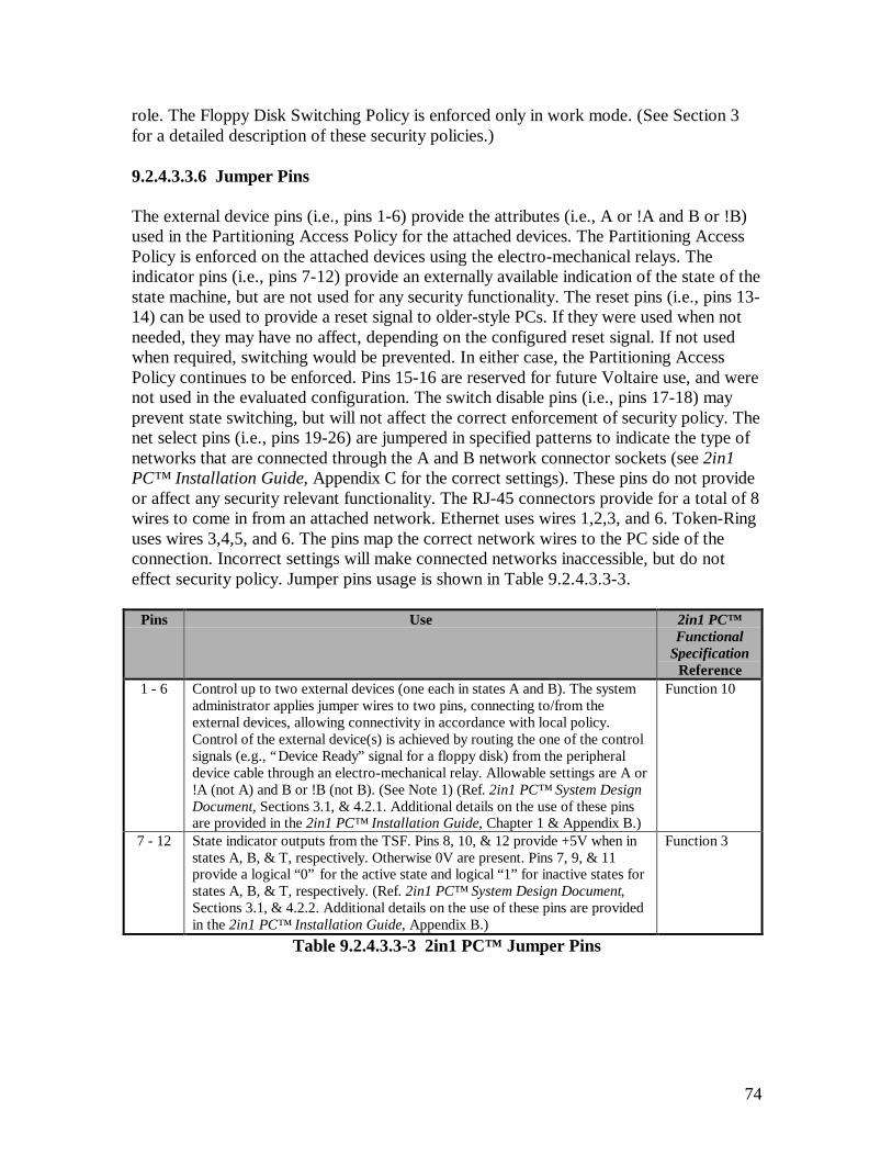
74
role. The Floppy Disk Switching Policy is enforced only in work mode. (See Section 3for a detailed description of these security policies.)
9.2.4.3.3.6 Jumper Pins
The external device pins (i.e., pins 1-6) provide the attributes (i.e., A or !A and B or !B)used in the Partitioning Access Policy for the attached devices. The Partitioning AccessPolicy is enforced on the attached devices using the electro-mechanical relays. Theindicator pins (i.e., pins 7-12) provide an externally available indication of the state of thestate machine, but are not used for any security functionality. The reset pins (i.e., pins 13-14) can be used to provide a reset signal to older-style PCs. If they were used when notneeded, they may have no affect, depending on the configured reset signal. If not usedwhen required, switching would be prevented. In either case, the Partitioning AccessPolicy continues to be enforced. Pins 15-16 are reserved for future Voltaire use, and werenot used in the evaluated configuration. The switch disable pins (i.e., pins 17-18) mayprevent state switching, but will not affect the correct enforcement of security policy. Thenet select pins (i.e., pins 19-26) are jumpered in specified patterns to indicate the type ofnetworks that are connected through the A and B network connector sockets (see 2in1PC™ Installation Guide, Appendix C for the correct settings). These pins do not provideor affect any security relevant functionality. The RJ-45 connectors provide for a total of 8wires to come in from an attached network. Ethernet uses wires 1,2,3, and 6. Token-Ringuses wires 3,4,5, and 6. The pins map the correct network wires to the PC side of theconnection. Incorrect settings will make connected networks inaccessible, but do noteffect security policy. Jumper pins usage is shown in Table 9.2.4.3.3-3.
Pins Use 2in1 PC™Functional
SpecificationReference
1 - 6 Control up to two external devices (one each in states A and B). The systemadministrator applies jumper wires to two pins, connecting to/from theexternal devices, allowing connectivity in accordance with local policy.Control of the external device(s) is achieved by routing the one of the controlsignals (e.g., “Device Ready” signal for a floppy disk) from the peripheraldevice cable through an electro-mechanical relay. Allowable settings are A or!A (not A) and B or !B (not B). (See Note 1) (Ref. 2in1 PC™ System DesignDocument, Sections 3.1, & 4.2.1. Additional details on the use of these pinsare provided in the 2in1 PC™ Installation Guide, Chapter 1 & Appendix B.)
Function 10
7 - 12 State indicator outputs from the TSF. Pins 8, 10, & 12 provide +5V when instates A, B, & T, respectively. Otherwise 0V are present. Pins 7, 9, & 11provide a logical “0” for the active state and logical “1” for inactive states forstates A, B, & T, respectively. (Ref. 2in1 PC™ System Design Document,Sections 3.1, & 4.2.2. Additional details on the use of these pins are providedin the 2in1 PC™ Installation Guide, Appendix B.)
Function 3
Table 9.2.4.3.3-3 2in1 PC™ Jumper Pins
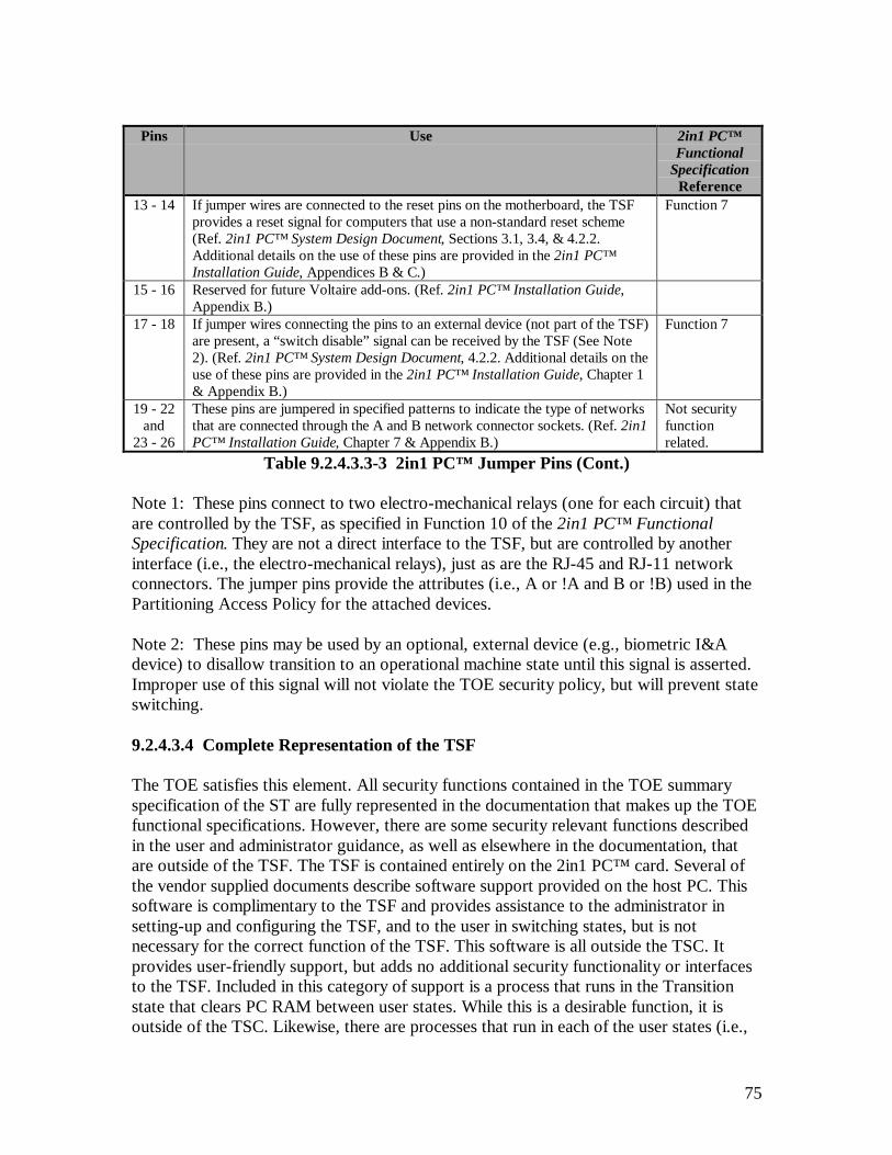
75
Pins Use 2in1 PC™Functional
SpecificationReference
13 - 14 If jumper wires are connected to the reset pins on the motherboard, the TSFprovides a reset signal for computers that use a non-standard reset scheme(Ref. 2in1 PC™ System Design Document, Sections 3.1, 3.4, & 4.2.2.Additional details on the use of these pins are provided in the 2in1 PC™Installation Guide, Appendices B & C.)
Function 7
15 - 16 Reserved for future Voltaire add-ons. (Ref. 2in1 PC™ Installation Guide,Appendix B.)
17 - 18 If jumper wires connecting the pins to an external device (not part of the TSF)are present, a “switch disable” signal can be received by the TSF (See Note2). (Ref. 2in1 PC™ System Design Document, 4.2.2. Additional details on theuse of these pins are provided in the 2in1 PC™ Installation Guide, Chapter 1& Appendix B.)
Function 7
19 - 22and
23 - 26
These pins are jumpered in specified patterns to indicate the type of networksthat are connected through the A and B network connector sockets. (Ref. 2in1PC™ Installation Guide, Chapter 7 & Appendix B.)
Not securityfunctionrelated.
Table 9.2.4.3.3-3 2in1 PC™ Jumper Pins (Cont.)
Note 1: These pins connect to two electro-mechanical relays (one for each circuit) thatare controlled by the TSF, as specified in Function 10 of the 2in1 PC™ FunctionalSpecification. They are not a direct interface to the TSF, but are controlled by anotherinterface (i.e., the electro-mechanical relays), just as are the RJ-45 and RJ-11 networkconnectors. The jumper pins provide the attributes (i.e., A or !A and B or !B) used in thePartitioning Access Policy for the attached devices.
Note 2: These pins may be used by an optional, external device (e.g., biometric I&Adevice) to disallow transition to an operational machine state until this signal is asserted.Improper use of this signal will not violate the TOE security policy, but will prevent stateswitching.
9.2.4.3.4 Complete Representation of the TSF
The TOE satisfies this element. All security functions contained in the TOE summaryspecification of the ST are fully represented in the documentation that makes up the TOEfunctional specifications. However, there are some security relevant functions describedin the user and administrator guidance, as well as elsewhere in the documentation, thatare outside of the TSF. The TSF is contained entirely on the 2in1 PC™ card. Several ofthe vendor supplied documents describe software support provided on the host PC. Thissoftware is complimentary to the TSF and provides assistance to the administrator insetting-up and configuring the TSF, and to the user in switching states, but is notnecessary for the correct function of the TSF. This software is all outside the TSC. Itprovides user-friendly support, but adds no additional security functionality or interfacesto the TSF. Included in this category of support is a process that runs in the Transitionstate that clears PC RAM between user states. While this is a desirable function, it isoutside of the TSC. Likewise, there are processes that run in each of the user states (i.e.,
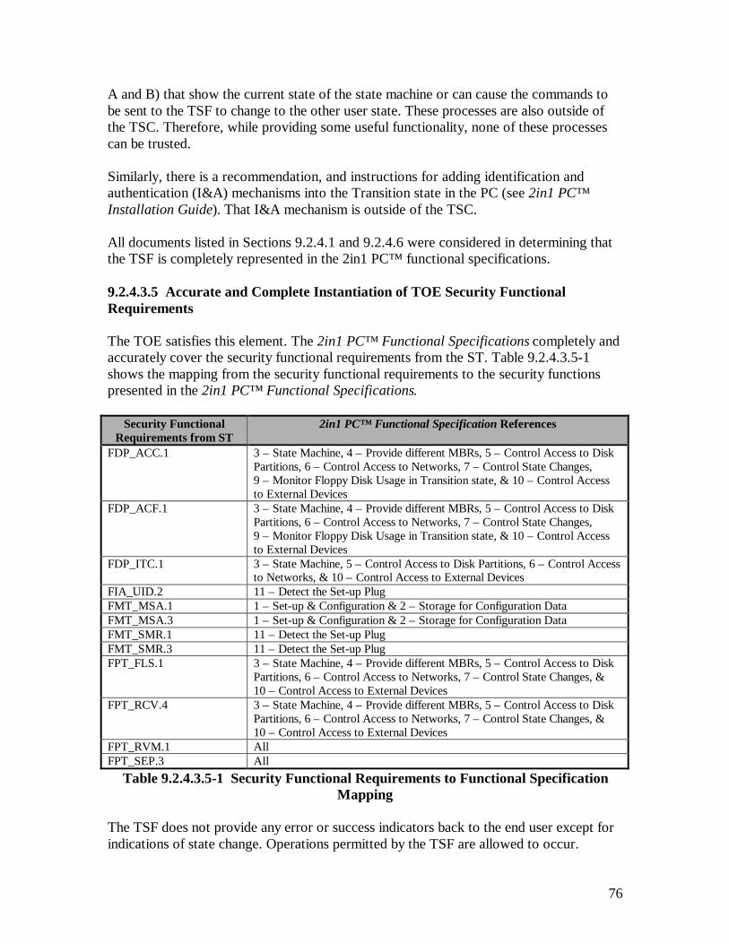
76
A and B) that show the current state of the state machine or can cause the commands tobe sent to the TSF to change to the other user state. These processes are also outside ofthe TSC. Therefore, while providing some useful functionality, none of these processescan be trusted.
Similarly, there is a recommendation, and instructions for adding identification andauthentication (I&A) mechanisms into the Transition state in the PC (see 2in1 PC™Installation Guide). That I&A mechanism is outside of the TSC.
All documents listed in Sections 9.2.4.1 and 9.2.4.6 were considered in determining thatthe TSF is completely represented in the 2in1 PC™ functional specifications.
9.2.4.3.5 Accurate and Complete Instantiation of TOE Security FunctionalRequirements
The TOE satisfies this element. The 2in1 PC™ Functional Specifications completely andaccurately cover the security functional requirements from the ST. Table 9.2.4.3.5-1shows the mapping from the security functional requirements to the security functionspresented in the 2in1 PC™ Functional Specifications.
Security FunctionalRequirements from ST
2in1 PC™ Functional Specification References
FDP_ACC.1 3 – State Machine, 4 – Provide different MBRs, 5 – Control Access to DiskPartitions, 6 – Control Access to Networks, 7 – Control State Changes,9 – Monitor Floppy Disk Usage in Transition state, & 10 – Control Accessto External Devices
FDP_ACF.1 3 – State Machine, 4 – Provide different MBRs, 5 – Control Access to DiskPartitions, 6 – Control Access to Networks, 7 – Control State Changes,9 – Monitor Floppy Disk Usage in Transition state, & 10 – Control Accessto External Devices
FDP_ITC.1 3 – State Machine, 5 – Control Access to Disk Partitions, 6 – Control Accessto Networks, & 10 – Control Access to External Devices
FIA_UID.2 11 – Detect the Set-up PlugFMT_MSA.1 1 – Set-up & Configuration & 2 – Storage for Configuration DataFMT_MSA.3 1 – Set-up & Configuration & 2 – Storage for Configuration DataFMT_SMR.1 11 – Detect the Set-up PlugFMT_SMR.3 11 – Detect the Set-up PlugFPT_FLS.1 3 – State Machine, 4 – Provide different MBRs, 5 – Control Access to Disk
Partitions, 6 – Control Access to Networks, 7 – Control State Changes, &10 – Control Access to External Devices
FPT_RCV.4 3 – State Machine, 4 – Provide different MBRs, 5 – Control Access to DiskPartitions, 6 – Control Access to Networks, 7 – Control State Changes, &10 – Control Access to External Devices
FPT_RVM.1 AllFPT_SEP.3 All
Table 9.2.4.3.5-1 Security Functional Requirements to Functional SpecificationMapping
The TSF does not provide any error or success indicators back to the end user except forindications of state change. Operations permitted by the TSF are allowed to occur.

77
Prohibited operations (e.g., read from a disk address outside the user’s allowed partitions)are not allowed to pass through the TSF to the hard disk, and no indication of success orfailure, and no data, are passed back to the user. The user visible indication of stateinformation is not trusted, so state change information presented to the user is also nottrusted. Regardless of what state the user thinks the TOE is in, the TSF enforces thesecurity policy for the actual state of the state machine.
9.2.4.6 Functional Specification Evidence
The following additional documentation was reviewed during the analysis of thefunctional specification:
• Voltaire 2in1 PC™ Security Target Report• E21198006, 2in1 PC™ Administrative Rights• E21198021, 2in1 PC™ Hardware Failure• E21198035, 2in1 PC™ Informal Security Policy Model• E21198046, 2in1 PC™ User Guide• E21198047, 2in1 PC™ Mapping of Assurance Elements• E21198063, 2in1 PC™ Installation Guide• E21198064, 2in1 PC™ Quick Installation Guide
9.2.5 ADV_HLD.1 Descriptive High-Level Design
9.2.5.1 Evidence Elements
This section addresses the high-level design of the TOE, provides a description of theTSF in terms of major structural units (i.e. subsystems), and relates these units to thefunctions that they provide. For each subsystem of the TSF, the high-level designdescribes every function, the purpose of each function, and identifies the securityfunctions contained in the subsystem. The interrelationships of all subsystems are alsodefined in the high-level design. These interrelationships are represented as externalinterfaces for data flow, control flow, etc., as appropriate.
9.2.5.2 Documentation Included in the High-Level Design
The following documentation was considered a part of the high-level design for the TOE:• E21198024, 2in1 PC™ System Design Document• E21198061, 2in1 PC™ Updates to the SYD EEPROM Mapping Section• E21199066, 2in1 PC™ Addendum to the System Design Document – High-Level
Design
9.2.5.3 Evaluator Action Elements and Findings

78
9.2.5.3.1 Informal High-Level Design
The TOE satisfies this element. The high-level design is in an informal style, written inEnglish.
9.2.5.3.2 Internal Consistency
The TOE satisfies this element. The high-level design is internally consistent. It containsno contradictory statements. The initial documentation, the 2in1 PC™ System DesignDocument, is incomplete, sometimes vague, and has a few errors in it. These problemshave been corrected with supplemental documentation provided by the developer,primarily the Addendum to the 2in1 PC™ System Design Document – High Level Design.The Addendum is consistent with the 2in1 PC™ System Design Document, and addsmore detail.
9.2.5.3.3 Structure of the TSF in Terms of Subsystems
The TOE satisfies this element. The high-level design is described in terms of blocks.There are four blocks described in the high-level design. They are the Main Block, IDEBlock, EEPROM Block, and the State Machine Block. Each of the blocks implements apart, or all, of the functions described in the functional specifications. The number andcomposition of the blocks is appropriate for the security functionality provided by theTOE. The functional decomposition into subsystems, and their descriptions, provided inthe high-level design is sufficient to provide a high-level understanding of design of theTSF. (Ref. 2in1 PC™ System Design Document, Section 4; Addendum to the 2in1 PC™System Design Document – High-Level Design; and 2in1 PC™ FunctionalSpecifications.)
9.2.5.3.4 Security Functionality Provided by Each Subsystem of the TSF
The TOE satisfies this element. The high-level design provides a description of thefunctional behavior of each of the four blocks. The following sections describe theblocks.
9.2.5.3.4.1 Main Block
The Main Block provides the external interface to the entire card. All external inputs andoutputs are channeled through the Main Block. Other blocks deal with externally visibleinputs and outputs, but they all pass through the Main Block. The other primary securityfunctions of the Main Block are:
• Manage security arbitration – allow or disallow IDE disk commands based on theresults of determinations made by the IDE Block (Function 5) and open and closeelectro-mechanical relays that control access to network connections (Function 6)and external devices (Function 10) based on mode and state information from theState Machine Block. (Ref. 2in1 PC™ System Design Document, Section 4.2.1;
79
Addendum to the 2in1 PC™ System Design Document – High-Level Design, MainBlock, Sections 3.1, 3.5, and 3.6; and 2in1 PC™ Functional Specifications.)
• Manage the reset mechanism – Monitor the IDE and ISA buses for any of thepossible reset signals or commands. When a reset is received, the Main Blocknotifies the State Machine Block (Function 7). (Ref. 2in1 PC™ System DesignDocument, Section 4.2.1; Addendum to the 2in1 PC™ System Design Document –High-Level Design, Main Block, Sections 3.3 and 3.4; and 2in1 PC™ FunctionalSpecifications.)
9.2.5.3.4.2 IDE Block
The IDE Block monitors IDE bus activity. The IDE Block looks for four specificconditions on the IDE bus and acts accordingly.
First, it looks for a read MBR (0,0,1). When a read MBR has been detected, the IDEBlock signals the EEPROM Block of the occurrence (Function 4). This process isfunctional only in work mode. When the TOE is in set-up mode, the MBR at physicaldisk location 0,0,1 (normally the MBR for the A partition) is used. (Ref. 2in1 PC™System Design Document, Section 4.2.3; Addendum to the 2in1 PC™ System DesignDocument – High-Level Design, IDE Block, Section 3.1; and 2in1 PC™ FunctionalSpecifications.)
The IDE Block also looks for 2in1 PC™ commands. When the “SWITCH” command isdetected, the IDE Block notifies the State Machine Block (Function 7). (Ref. 2in1 PC™System Design Document, Section 4.2.3; Addendum to the 2in1 PC™ System DesignDocument – High-Level Design, IDE Block, Section 3.1; and 2in1 PC™ FunctionalSpecifications.)
When a read or write command to the EEPROM is detected, the IDE Block notifies theEEPROM Block (Functions 1 and 2). (Ref. 2in1 PC™ System Design Document, Section4.2.3; Addendum to the 2in1 PC™ System Design Document – High-Level Design, IDEBlock, Section 3.1; and 2in1 PC™ Functional Specifications.)
The IDE Block also looks for any I/O command for the disk (Function 5). When a diskI/O command is detected, the IDE Block compares the disk address provided with thedisk boundary addresses for the different disk partitions. Then, based on the currentmachine state provided by the State Machine Block and partition boundary informationprovided by the EEPROM block, the IDE Block does the following checks and resultingnotifications:
1. Is the disk address within the partition associated with the current state orwithin the Functional partition?a. If not, signal the Main Block to block the command.b. Otherwise, is the access type (i.e., read or write) authorised for that
partition by the current machine state?
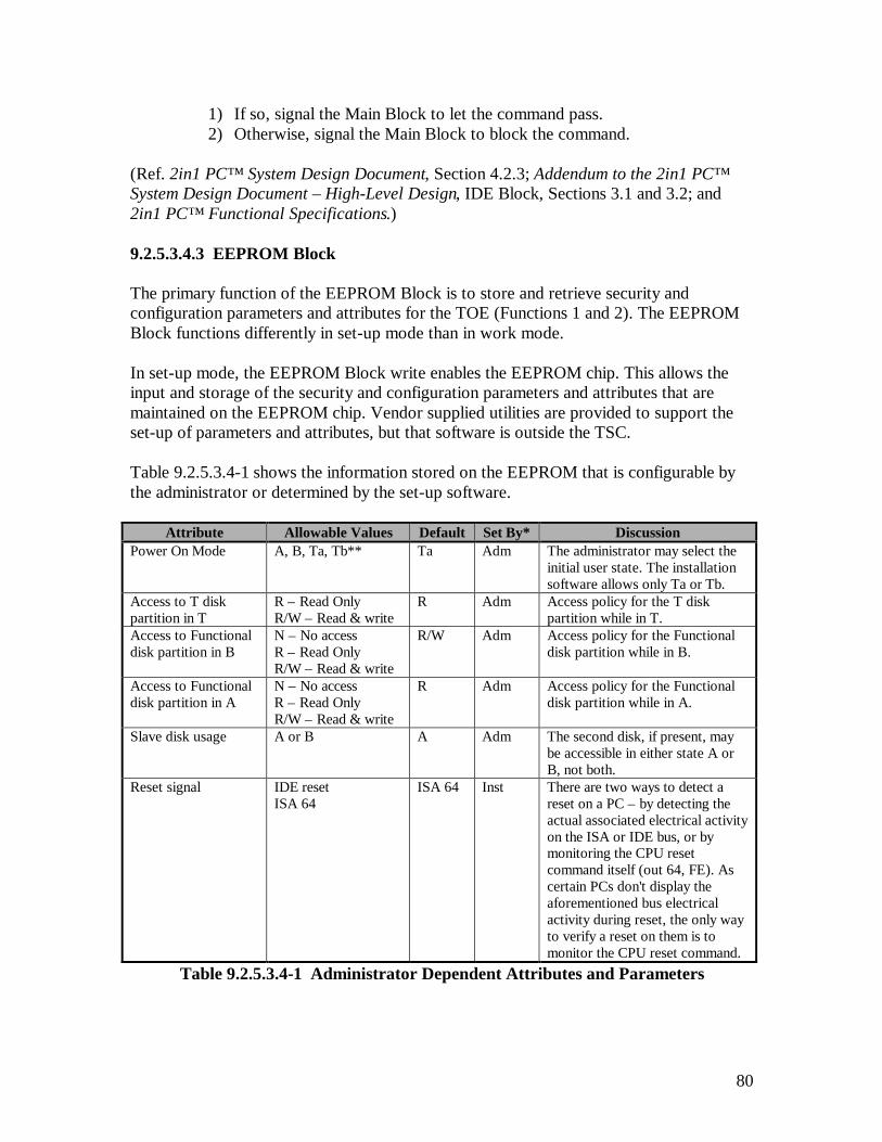
80
1) If so, signal the Main Block to let the command pass.2) Otherwise, signal the Main Block to block the command.
(Ref. 2in1 PC™ System Design Document, Section 4.2.3; Addendum to the 2in1 PC™System Design Document – High-Level Design, IDE Block, Sections 3.1 and 3.2; and2in1 PC™ Functional Specifications.)
9.2.5.3.4.3 EEPROM Block
The primary function of the EEPROM Block is to store and retrieve security andconfiguration parameters and attributes for the TOE (Functions 1 and 2). The EEPROMBlock functions differently in set-up mode than in work mode.
In set-up mode, the EEPROM Block write enables the EEPROM chip. This allows theinput and storage of the security and configuration parameters and attributes that aremaintained on the EEPROM chip. Vendor supplied utilities are provided to support theset-up of parameters and attributes, but that software is outside the TSC.
Table 9.2.5.3.4-1 shows the information stored on the EEPROM that is configurable bythe administrator or determined by the set-up software.
Attribute Allowable Values Default Set By* DiscussionPower On Mode A, B, Ta, Tb** Ta Adm The administrator may select the
initial user state. The installationsoftware allows only Ta or Tb.
Access to T diskpartition in T
R – Read OnlyR/W – Read & write
R Adm Access policy for the T diskpartition while in T.
Access to Functionaldisk partition in B
N – No accessR – Read OnlyR/W – Read & write
R/W Adm Access policy for the Functionaldisk partition while in B.
Access to Functionaldisk partition in A
N – No accessR – Read OnlyR/W – Read & write
R Adm Access policy for the Functionaldisk partition while in A.
Slave disk usage A or B A Adm The second disk, if present, maybe accessible in either state A orB, not both.
Reset signal IDE resetISA 64
ISA 64 Inst There are two ways to detect areset on a PC – by detecting theactual associated electrical activityon the ISA or IDE bus, or bymonitoring the CPU resetcommand itself (out 64, FE). Ascertain PCs don't display theaforementioned bus electricalactivity during reset, the only wayto verify a reset on them is tomonitor the CPU reset command.
Table 9.2.5.3.4-1 Administrator Dependent Attributes and Parameters
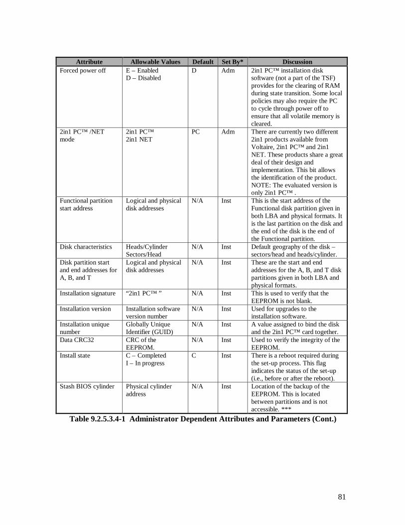
81
Attribute Allowable Values Default Set By* DiscussionForced power off E – Enabled
D – DisabledD Adm 2in1 PC™ installation disk
software (not a part of the TSF)provides for the clearing of RAMduring state transition. Some localpolicies may also require the PCto cycle through power off toensure that all volatile memory iscleared.
2in1 PC™ /NETmode
2in1 PC™2in1 NET
PC Adm There are currently two different2in1 products available fromVoltaire, 2in1 PC™ and 2in1NET. These products share a greatdeal of their design andimplementation. This bit allowsthe identification of the product.NOTE: The evaluated version isonly 2in1 PC™ .
Functional partitionstart address
Logical and physicaldisk addresses
N/A Inst This is the start address of theFunctional disk partition given inboth LBA and physical formats. Itis the last partition on the disk andthe end of the disk is the end ofthe Functional partition.
Disk characteristics Heads/CylinderSectors/Head
N/A Inst Default geography of the disk –sectors/head and heads/cylinder.
Disk partition startand end addresses forA, B, and T
Logical and physicaldisk addresses
N/A Inst These are the start and endaddresses for the A, B, and T diskpartitions given in both LBA andphysical formats.
Installation signature “2in1 PC™ ” N/A Inst This is used to verify that theEEPROM is not blank.
Installation version Installation softwareversion number
N/A Inst Used for upgrades to theinstallation software.
Installation uniquenumber
Globally UniqueIdentifier (GUID)
N/A Inst A value assigned to bind the diskand the 2in1 PC™ card together.
Data CRC32 CRC of theEEPROM.
N/A Inst Used to verify the integrity of theEEPROM.
Install state C – CompletedI – In progress
C Inst There is a reboot required duringthe set-up process. This flagindicates the status of the set-up(i.e., before or after the reboot).
Stash BIOS cylinder Physical cylinderaddress
N/A Inst Location of the backup of theEEPROM. This is locatedbetween partitions and is notaccessible. ***
Table 9.2.5.3.4-1 Administrator Dependent Attributes and Parameters (Cont.)

82
Attribute Allowable Values Default Set By* DiscussionMBRs for A, B, andT
Boot loader andsystem tables.
N/A Inst These are the actual MBRs to beused for booting from the A, B,and T disk partitions.
* Adm means specifically set by the administrator. Inst means the value is determined by the set-upsoftware, depending on administrator selected parameters.** Ta and Tb are the Transition state where the next state has been identified as A or B, respectively.*** The stash is a mirror image of the EEPROM that is saved to facilitate recovery from a damaged ormalfunctioning 2in1 PC card. It has no security function. Without this information, much of the data onthe hard disk would be difficult to recover and my be completely lost, in the event of a failure. The stashresides in a gap between partitions, and therefore is never accessible in WORK mode (when you're inpartition A it is above your highest accessible sector, when you're in T and B, it's below your lowestaccessible sector). The "Stash BIOS cylinder" item in the EEPROM is the address of the cylinder in whichthe stash is located. It's used to assist in locating the stash when it needs to be updated (and not having tosequentially search the entire disk for it - a lengthy process).
Table 9.2.5.3.4-1 Administrator Dependent Attributes and Parameters (Cont.)
(Ref. 2in1 PC™ System Design Document, Section 4.2.4 and Appendices A and B;Addendum to the 2in1 PC™ System Design Document – High-Level Design, EEPROMBlock, Sections 3.1 and 3.3; and 2in1 PC™ Functional Specifications.)
When the IDE Block notifies the EEPROM Block that a read MBR has been detected,and based on machine state obtained from the State Machine Block, the EEPROM Blockprovides MBR data appropriate for that state, to the IDE bus (Function 4). This providesthe capability to boot the operating system from the appropriate disk partition for themachine state. For example, when the TOE transitions into state A, the system is bootedfrom the A partition. (Ref. 2in1 PC™ System Design Document, Section 4.2.4;Addendum to the 2in1 PC™ System Design Document – High-Level Design, EEPROMBlock, Sections 3.2 and 3.4; and 2in1 PC™ Functional Specifications.)
The IDE Block also responds to requests for data both internal to the TSF and to externalsources. External requests for EEPROM data come through the IDE Block (Function 2).(Ref. 2in1 PC™ System Design Document, Section 4.2.4; Addendum to the 2in1 PC™System Design Document – High-Level Design, EEPROM Block, Section 3.2; and 2in1PC™ Functional Specifications.)
9.2.5.3.4.4 State Machine Block
The State Machine Block provides the state machine for the TOE. It controls andmaintains both the mode (i.e., set-up or work) and the state (i.e., A, B, or T) of the TOE.
When the system (i.e., PC and TOE) is powered-on, the State Machine Block checks theset-up pins for the presence of a set-up plug. If the set-up plug is detected, the TOE is putinto set-up mode (Function 11). In set-up mode, the machine states (i.e., A, B, and T) donot apply, and that part of the state machine is not active. (Ref. 2in1 PC™ System DesignDocument, Section 4.2.2; Addendum to the 2in1 PC™ System Design Document – High-Level Design, State Machine Block, Section 3.1; and 2in1 PC™ FunctionalSpecifications.)
83
When the TOE is not in set-up mode, it is in work mode. In work mode, the machinestates (i.e., A, B, and T) are maintained by the state machine (Functions 3 and 7). Achange of machine state requires two specific events to occur. First, a “SWITCH”command must be received from the IDE block. The next state is determined based onthe current machine state, an internal flag that indicates the next user state, and thedirection of the switch (i.e., switching from A or from B). The state will actually changewhen the next reset signal is received from the Main Block. (Ref. 2in1 PC™ SystemDesign Document, Section 4.2.2; Addendum to the 2in1 PC™ System Design Document– High-Level Design, State Machine Block, Sections 3.4 and 3.5; and 2in1 PC™Functional Specifications.) There are three conditions that may prevent state switching,depending on the administrator defined and configured options. They are:
1. Forced Shutdown – There is an administrator selectable option that requires a full,hard boot, between user states (i.e., A and B). When this option is selected, onlyone state transition is allowed (e.g., T –> A or T –> B) before state switching isdisabled (Function 7). When the State Machine Block determines that it was ahard boot (i.e., power-on), a flag is cleared to indicate initial state. The firstpower-on state is determined from configuration information obtained from theEEPROM Block (bits 1-2 of the first word on the EEPROM chip). At the nextreset signal, the flag will be set, indicating that the one allowed switch has takenplace. No additional state switches will be honored after the flag is set. (Ref. 2in1PC™ System Design Document, Section 4.2.2; Addendum to the 2in1 PC™System Design Document – High-Level Design, State Machine Block, Sections3.2, 3.4 and 3.6; and 2in1 PC™ Functional Specifications.)
2. DMA2 (DRQ2) Activity – There is an administrator selectable option thatprevents the state machine from leaving the transition (T) state if any DMA2activity has been detected during that state (Function 9). DMA2 (DRQ2) activityis generally associated with the floppy disk. (Note: There is a possibility thatDMA2 could be associated with another device (e.g., sound card). If that were tooccur, switching would also be prevented by access to the sound card, and wouldstill not violate the security policy.) This detection is performed by the DMAcontroller receiving DMA2 activity from the ISA bus only. Since PCI devices donot interface with the DMA controller, their operation is not monitored by theTSF. When DMA2 activity is detected during the Transition state, the system(PC & TOE) must be rebooted, through Transition state again, without any furtherDMA2 activity, before it is allowed to continue on to a user state (i.e., A or B).(Ref. 2in1 PC™ System Design Document, Section 4.2.2; Addendum to the 2in1PC™ System Design Document – High-Level Design, State Machine Block,Sections 3.3 and 3.4; and 2in1 PC™ Functional Specifications.)
3. Switch Disable – There are jumper pins (i.e., 17-18) on the 2in1 PC™ card thatmay disable switching. As long as a signal is asserted (i.e., +5v) on these pins,switching is disabled (Function 7). This feature was included in the TOE toprovide an optional, external device, such as a biometric I&A device, to be used
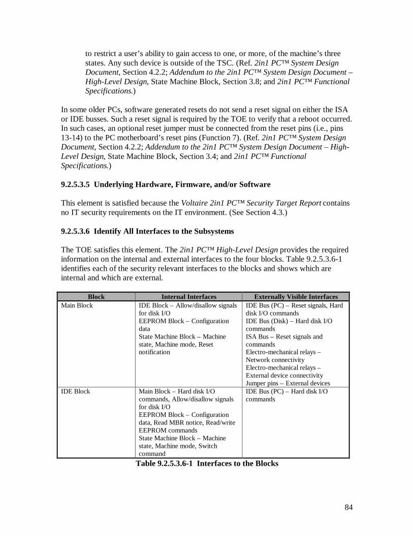
84
to restrict a user’s ability to gain access to one, or more, of the machine’s threestates. Any such device is outside of the TSC. (Ref. 2in1 PC™ System DesignDocument, Section 4.2.2; Addendum to the 2in1 PC™ System Design Document –High-Level Design, State Machine Block, Section 3.8; and 2in1 PC™ FunctionalSpecifications.)
In some older PCs, software generated resets do not send a reset signal on either the ISAor IDE busses. Such a reset signal is required by the TOE to verify that a reboot occurred.In such cases, an optional reset jumper must be connected from the reset pins (i.e., pins13-14) to the PC motherboard’s reset pins (Function 7). (Ref. 2in1 PC™ System DesignDocument, Section 4.2.2; Addendum to the 2in1 PC™ System Design Document – High-Level Design, State Machine Block, Section 3.4; and 2in1 PC™ FunctionalSpecifications.)
9.2.5.3.5 Underlying Hardware, Firmware, and/or Software
This element is satisfied because the Voltaire 2in1 PC™ Security Target Report containsno IT security requirements on the IT environment. (See Section 4.3.)
9.2.5.3.6 Identify All Interfaces to the Subsystems
The TOE satisfies this element. The 2in1 PC™ High-Level Design provides the requiredinformation on the internal and external interfaces to the four blocks. Table 9.2.5.3.6-1identifies each of the security relevant interfaces to the blocks and shows which areinternal and which are external.
Block Internal Interfaces Externally Visible InterfacesMain Block IDE Block – Allow/disallow signals
for disk I/OEEPROM Block – ConfigurationdataState Machine Block – Machinestate, Machine mode, Resetnotification
IDE Bus (PC) – Reset signals, Harddisk I/O commandsIDE Bus (Disk) – Hard disk I/OcommandsISA Bus – Reset signals andcommandsElectro-mechanical relays –Network connectivityElectro-mechanical relays –External device connectivityJumper pins – External devices
IDE Block Main Block – Hard disk I/Ocommands, Allow/disallow signalsfor disk I/OEEPROM Block – Configurationdata, Read MBR notice, Read/writeEEPROM commandsState Machine Block – Machinestate, Machine mode, Switchcommand
IDE Bus (PC) – Hard disk I/Ocommands
Table 9.2.5.3.6-1 Interfaces to the Blocks
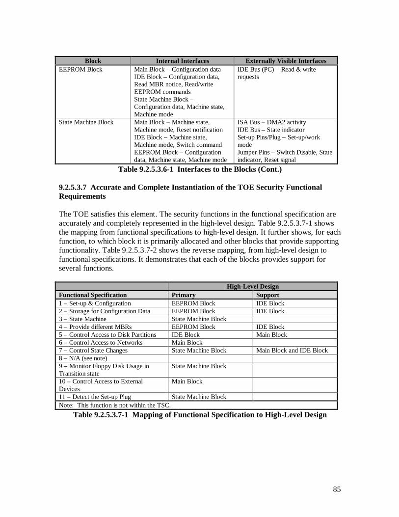
85
Block Internal Interfaces Externally Visible InterfacesEEPROM Block Main Block – Configuration data
IDE Block – Configuration data,Read MBR notice, Read/writeEEPROM commandsState Machine Block –Configuration data, Machine state,Machine mode
IDE Bus (PC) – Read & writerequests
State Machine Block Main Block – Machine state,Machine mode, Reset notificationIDE Block – Machine state,Machine mode, Switch commandEEPROM Block – Configurationdata, Machine state, Machine mode
ISA Bus – DMA2 activityIDE Bus – State indicatorSet-up Pins/Plug – Set-up/workmodeJumper Pins – Switch Disable, Stateindicator, Reset signal
Table 9.2.5.3.6-1 Interfaces to the Blocks (Cont.)
9.2.5.3.7 Accurate and Complete Instantiation of the TOE Security FunctionalRequirements
The TOE satisfies this element. The security functions in the functional specification areaccurately and completely represented in the high-level design. Table 9.2.5.3.7-1 showsthe mapping from functional specifications to high-level design. It further shows, for eachfunction, to which block it is primarily allocated and other blocks that provide supportingfunctionality. Table 9.2.5.3.7-2 shows the reverse mapping, from high-level design tofunctional specifications. It demonstrates that each of the blocks provides support forseveral functions.
High-Level DesignFunctional Specification Primary Support1 – Set-up & Configuration EEPROM Block IDE Block2 – Storage for Configuration Data EEPROM Block IDE Block3 – State Machine State Machine Block4 – Provide different MBRs EEPROM Block IDE Block5 – Control Access to Disk Partitions IDE Block Main Block6 – Control Access to Networks Main Block7 – Control State Changes State Machine Block Main Block and IDE Block8 – N/A (see note)9 – Monitor Floppy Disk Usage inTransition state
State Machine Block
10 – Control Access to ExternalDevices
Main Block
11 – Detect the Set-up Plug State Machine BlockNote: This function is not within the TSC.
Table 9.2.5.3.7-1 Mapping of Functional Specification to High-Level Design
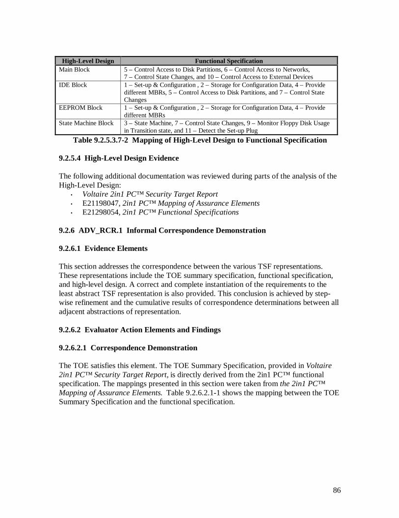
86
High-Level Design Functional SpecificationMain Block 5 – Control Access to Disk Partitions, 6 – Control Access to Networks,
7 – Control State Changes, and 10 – Control Access to External DevicesIDE Block 1 – Set-up & Configuration , 2 – Storage for Configuration Data, 4 – Provide
different MBRs, 5 – Control Access to Disk Partitions, and 7 – Control StateChanges
EEPROM Block 1 – Set-up & Configuration , 2 – Storage for Configuration Data, 4 – Providedifferent MBRs
State Machine Block 3 – State Machine, 7 – Control State Changes, 9 – Monitor Floppy Disk Usagein Transition state, and 11 – Detect the Set-up Plug
Table 9.2.5.3.7-2 Mapping of High-Level Design to Functional Specification
9.2.5.4 High-Level Design Evidence
The following additional documentation was reviewed during parts of the analysis of theHigh-Level Design:
• Voltaire 2in1 PC™ Security Target Report• E21198047, 2in1 PC™ Mapping of Assurance Elements• E21298054, 2in1 PC™ Functional Specifications
9.2.6 ADV_RCR.1 Informal Correspondence Demonstration
9.2.6.1 Evidence Elements
This section addresses the correspondence between the various TSF representations.These representations include the TOE summary specification, functional specification,and high-level design. A correct and complete instantiation of the requirements to theleast abstract TSF representation is also provided. This conclusion is achieved by step-wise refinement and the cumulative results of correspondence determinations between alladjacent abstractions of representation.
9.2.6.2 Evaluator Action Elements and Findings
9.2.6.2.1 Correspondence Demonstration
The TOE satisfies this element. The TOE Summary Specification, provided in Voltaire2in1 PC™ Security Target Report, is directly derived from the 2in1 PC™ functionalspecification. The mappings presented in this section were taken from the 2in1 PC™Mapping of Assurance Elements. Table 9.2.6.2.1-1 shows the mapping between the TOESummary Specification and the functional specification.

87
Functions Functional SpecificationSET-UP 1 – Set-up & ConfigurationSTORE 2 – Storage for Configuration DataSTATE 3 – State MachineBOOT 4 – Provide different MBRsAC_DISK 5 – Control Access to Disk PartitionsAC_NW 6 – Control Access to NetworksCHANGE 7 – Control State ChangesFLOPPY 9 – Monitor Floppy Disk Usage in Transition stateAC_DEV 10 – Control Access to External DevicesMODE 11 – Detect the Set-up Plug
Table 9.2.6.2.1-1 Functions to Security Functional Requirements Mapping
Table 9.2.6.2.1-2 shows the mapping of the security functional requirements from the STto the security functions presented in the 2in1 PC™ Functional Specifications.
Security FunctionalRequirements
2in1 PC™ Functional Specification References
FDP_ACC.1 3 – State Machine, 4 – Provide different MBRs, 5 – Control Access to DiskPartitions, 6 – Control Access to Networks, 7 – Control State Changes, 9 –Monitor Floppy Disk Usage in Transition state, & 10 – Control Access toExternal Devices
FDP_ACF.1 3 – State Machine, 4 – Provide different MBRs, 5 – Control Access to DiskPartitions, 6 – Control Access to Networks, 7 – Control State Changes, 9 –Monitor Floppy Disk Usage in Transition state, & 10 – Control Access toExternal Devices
FDP_ITC.1 3 – State Machine, 5 – Control Access to Disk Partitions, 6 – Control Access toNetworks, & 10 – Control Access to External Devices
FIA_UID.2 11 – Detect the Set-up PlugFMT_MSA.1 1 – Set-up & Configuration, & 2 – Storage for Configuration DataFMT_MSA.3 1 – Set-up & Configuration, & 2 – Storage for Configuration DataFMT_SMR.1 11 – Detect the Set-up PlugFMT_SMR.3 11 – Detect the Set-up PlugFPT_FLS.1 3 – State Machine, 4 – Provide different MBRs, 5 – Control Access to Disk
Partitions, 6 – Control Access to Networks, 7 – Control State Changes, & 10 –Control Access to External Devices
FPT_RCV.4 3 – State Machine, 4 – Provide different MBRs, 5 – Control Access to DiskPartitions, 6 – Control Access to Networks, 7 – Control State Changes, & 10 –Control Access to External Devices
FPT_RVM.1 AllFPT_SEP.3 All
Table 9.2.6.2.1-2 Security Functional Requirements to Functional SpecificationMapping
Table 9.2.6.2.1-3 shows the mapping of functional specifications to high-level design. Itfurther shows, for each function, to which block it is primarily allocated and other blocksthat provide supporting functionality. Table 9.2.6.2.1-4 shows the reverse mapping, fromhigh-level design to functional specifications. It demonstrates that each of the blocksprovides support for several functions.

88
Functional Specification High-Level Design(Primary)
High-Level Design(Support)
1 – Set-up & Configuration EEPROM Block IDE Block2 – Storage for Configuration Data EEPROM Block IDE Block3 – State Machine State Machine Block4 – Provide different MBRs EEPROM Block IDE Block5 – Control Access to Disk Partitions IDE Block Main Block6 – Control Access to Networks Main Block7 – Control State Changes State Machine Block Main Block and IDE Block8 – N/A (see note)9 – Monitor Floppy Disk Usage inTransition state
State Machine Block
10 – Control Access to ExternalDevices
Main Block
11 – Detect the Set-up Plug State Machine BlockNote: This function is not within the TSC.
Table 9.2.6.2.1-3 Mapping of Functional Specification to High-Level Design
High-Level Design Functional SpecificationMain Block 5 – Control Access to Disk Partitions, 6 – Control Access to Networks, 7 –
Control State Changes, and 10 – Control Access to External DevicesIDE Block 1 – Set-up & Configuration , 2 – Storage for Configuration Data, 4 – Provide
different MBRs, 5 – Control Access to Disk Partitions, and 7 – Control StateChanges
EEPROM Block 1 – Set-up & Configuration , 2 – Storage for Configuration Data, 4 – Providedifferent MBRs
State Machine Block 3 – State Machine, 7 – Control State Changes, 9 – Monitor Floppy Disk Usagein Transition state, and 11 – Detect the Set-up Plug
Table 9.2.6.2.1-4 Mapping of High-Level Design to Functional Specification
9.2.6.3 Informal Correspondence Evidence
The following additional documentation was reviewed during the analysis of the InformalCorrespondence Demonstration:
• Voltaire 2in1 PC™ Security Target Report• E21198024, 2in1 PC™ System Design Document• E21298054, 2in1 PC™ Functional Specifications• E21198061, 2in1 PC™ Updates to the SYD EEPROM Mapping Section• E21199066, 2in1 PC™ Addendum to the System Design Document – High-Level
Design
9.2.7 ADV_SPM.1 Informal TOE Security Policy Model
9.2.7.1 Evidence Elements
This section addresses the informal TOE security policy model. This model is defined ina consistent manner and fully describes the TSP rules, characteristics, and provides acorrespondence between the TSP and the functional specification. This correspondencedemonstrates that all of the security functions defined in the functional specification areconsistent and complete with respect to the TSP model.
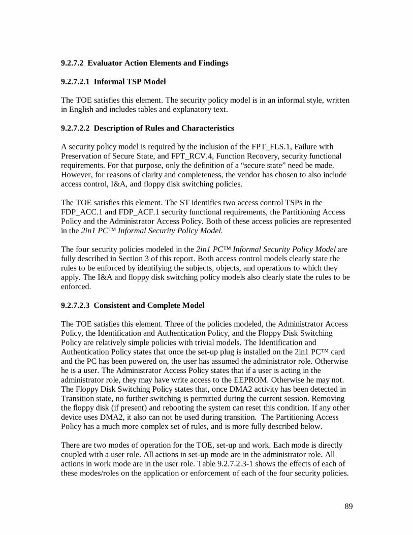
89
9.2.7.2 Evaluator Action Elements and Findings
9.2.7.2.1 Informal TSP Model
The TOE satisfies this element. The security policy model is in an informal style, writtenin English and includes tables and explanatory text.
9.2.7.2.2 Description of Rules and Characteristics
A security policy model is required by the inclusion of the FPT_FLS.1, Failure withPreservation of Secure State, and FPT_RCV.4, Function Recovery, security functionalrequirements. For that purpose, only the definition of a “secure state” need be made.However, for reasons of clarity and completeness, the vendor has chosen to also includeaccess control, I&A, and floppy disk switching policies.
The TOE satisfies this element. The ST identifies two access control TSPs in theFDP_ACC.1 and FDP_ACF.1 security functional requirements, the Partitioning AccessPolicy and the Administrator Access Policy. Both of these access policies are representedin the 2in1 PC™ Informal Security Policy Model.
The four security policies modeled in the 2in1 PC™ Informal Security Policy Model arefully described in Section 3 of this report. Both access control models clearly state therules to be enforced by identifying the subjects, objects, and operations to which theyapply. The I&A and floppy disk switching policy models also clearly state the rules to beenforced.
9.2.7.2.3 Consistent and Complete Model
The TOE satisfies this element. Three of the policies modeled, the Administrator AccessPolicy, the Identification and Authentication Policy, and the Floppy Disk SwitchingPolicy are relatively simple policies with trivial models. The Identification andAuthentication Policy states that once the set-up plug is installed on the 2in1 PC™ cardand the PC has been powered on, the user has assumed the administrator role. Otherwisehe is a user. The Administrator Access Policy states that if a user is acting in theadministrator role, they may have write access to the EEPROM. Otherwise he may not.The Floppy Disk Switching Policy states that, once DMA2 activity has been detected inTransition state, no further switching is permitted during the current session. Removingthe floppy disk (if present) and rebooting the system can reset this condition. If any otherdevice uses DMA2, it also can not be used during transition. The Partitioning AccessPolicy has a much more complex set of rules, and is more fully described below.
There are two modes of operation for the TOE, set-up and work. Each mode is directlycoupled with a user role. All actions in set-up mode are in the administrator role. Allactions in work mode are in the user role. Table 9.2.7.2.3-1 shows the effects of each ofthese modes/roles on the application or enforcement of each of the four security policies.
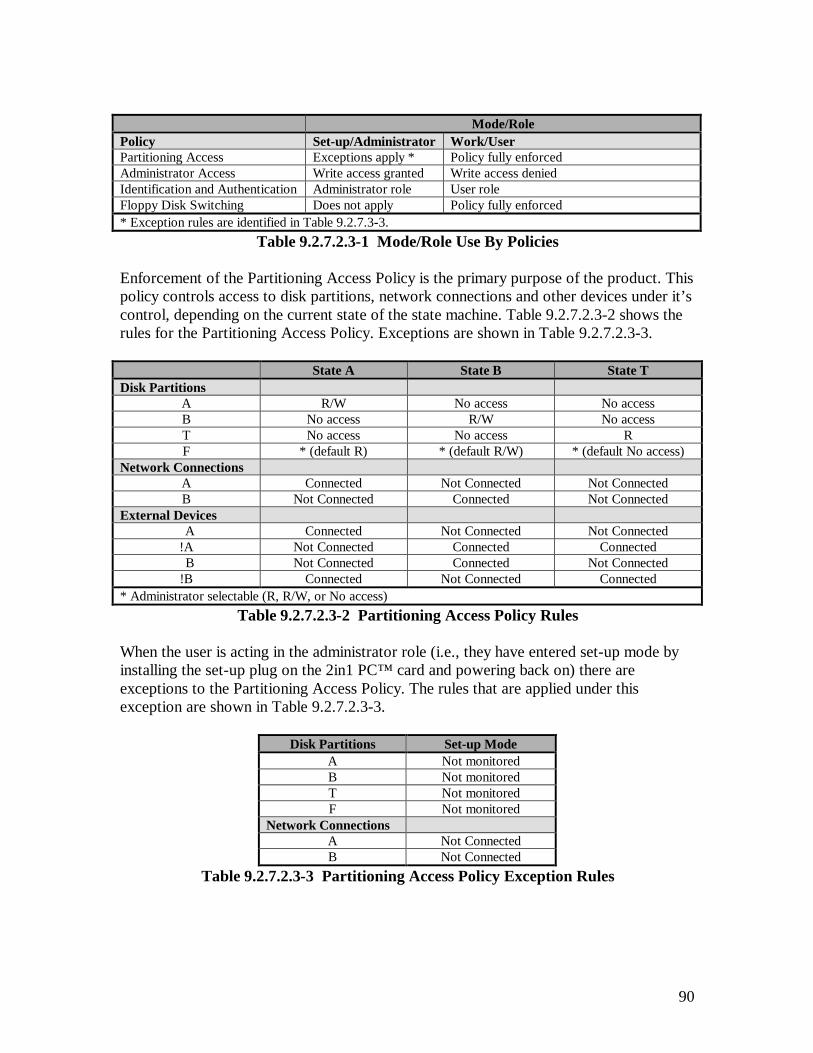
90
Mode/RolePolicy Set-up/Administrator Work/UserPartitioning Access Exceptions apply * Policy fully enforcedAdministrator Access Write access granted Write access deniedIdentification and Authentication Administrator role User roleFloppy Disk Switching Does not apply Policy fully enforced* Exception rules are identified in Table 9.2.7.3-3.
Table 9.2.7.2.3-1 Mode/Role Use By Policies
Enforcement of the Partitioning Access Policy is the primary purpose of the product. Thispolicy controls access to disk partitions, network connections and other devices under it’scontrol, depending on the current state of the state machine. Table 9.2.7.2.3-2 shows therules for the Partitioning Access Policy. Exceptions are shown in Table 9.2.7.2.3-3.
State A State B State TDisk Partitions
A R/W No access No accessB No access R/W No accessT No access No access RF * (default R) * (default R/W) * (default No access)
Network ConnectionsA Connected Not Connected Not ConnectedB Not Connected Connected Not Connected
External Devices A Connected Not Connected Not Connected!A Not Connected Connected Connected B Not Connected Connected Not Connected!B Connected Not Connected Connected
* Administrator selectable (R, R/W, or No access)Table 9.2.7.2.3-2 Partitioning Access Policy Rules
When the user is acting in the administrator role (i.e., they have entered set-up mode byinstalling the set-up plug on the 2in1 PC™ card and powering back on) there areexceptions to the Partitioning Access Policy. The rules that are applied under thisexception are shown in Table 9.2.7.2.3-3.
Disk Partitions Set-up ModeA Not monitoredB Not monitoredT Not monitoredF Not monitored
Network ConnectionsA Not ConnectedB Not Connected
Table 9.2.7.2.3-3 Partitioning Access Policy Exception Rules
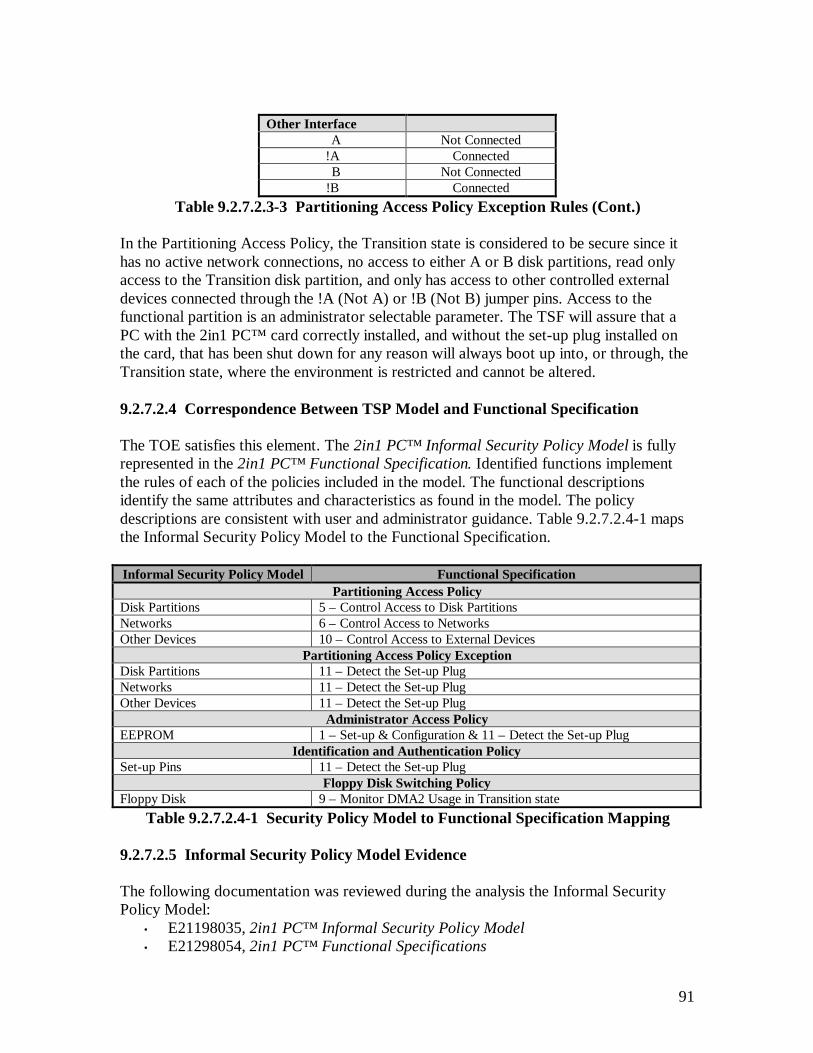
91
Other Interface A Not Connected!A Connected B Not Connected!B Connected
Table 9.2.7.2.3-3 Partitioning Access Policy Exception Rules (Cont.)
In the Partitioning Access Policy, the Transition state is considered to be secure since ithas no active network connections, no access to either A or B disk partitions, read onlyaccess to the Transition disk partition, and only has access to other controlled externaldevices connected through the !A (Not A) or !B (Not B) jumper pins. Access to thefunctional partition is an administrator selectable parameter. The TSF will assure that aPC with the 2in1 PC™ card correctly installed, and without the set-up plug installed onthe card, that has been shut down for any reason will always boot up into, or through, theTransition state, where the environment is restricted and cannot be altered.
9.2.7.2.4 Correspondence Between TSP Model and Functional Specification
The TOE satisfies this element. The 2in1 PC™ Informal Security Policy Model is fullyrepresented in the 2in1 PC™ Functional Specification. Identified functions implementthe rules of each of the policies included in the model. The functional descriptionsidentify the same attributes and characteristics as found in the model. The policydescriptions are consistent with user and administrator guidance. Table 9.2.7.2.4-1 mapsthe Informal Security Policy Model to the Functional Specification.
Informal Security Policy Model Functional SpecificationPartitioning Access Policy
Disk Partitions 5 – Control Access to Disk PartitionsNetworks 6 – Control Access to NetworksOther Devices 10 – Control Access to External Devices
Partitioning Access Policy ExceptionDisk Partitions 11 – Detect the Set-up PlugNetworks 11 – Detect the Set-up PlugOther Devices 11 – Detect the Set-up Plug
Administrator Access PolicyEEPROM 1 – Set-up & Configuration & 11 – Detect the Set-up Plug
Identification and Authentication PolicySet-up Pins 11 – Detect the Set-up Plug
Floppy Disk Switching PolicyFloppy Disk 9 – Monitor DMA2 Usage in Transition state
Table 9.2.7.2.4-1 Security Policy Model to Functional Specification Mapping
9.2.7.2.5 Informal Security Policy Model Evidence
The following documentation was reviewed during the analysis the Informal SecurityPolicy Model:
• E21198035, 2in1 PC™ Informal Security Policy Model• E21298054, 2in1 PC™ Functional Specifications
92
• E21198046, 2in1 PC™ User Guide• E21198063, 2in1 PC™ Installation Guide• E21198064, 2in1 PC™ Quick Installation Guide
9.2.8 AGD_ADM.1 Administrator Guidance
9.2.8.1 Evidence Elements
This section presents the results of the evaluation of administrator guidance providedwith the TOE. The administrator guidance is contained in the 2in1 PC™ InstallationGuide and is supplemented by 2in1 PC™ Application Notes. The administrator functionis invoked in the set-up mode through the use of an internal or external set-up plug asapplicable.
9.2.8.2 Evaluator Action Elements and Findings
9.2.8.2.1 Describe Administrative Functions and Interfaces
The administrator guidance satisfies this element by providing a detailed overview of theTOE security functionality available to the administrator in the set-up mode (Ref. 2in1PC™ Installation Guide, Chapter 1). It also provides step-by-step set-up modeprocedures, configuration settings, and descriptions of the necessary actions and expectedresults when using the appropriate keyboard or mouse inputs for the Windows3.1/95/NT, and MS-DOS operating systems (Ref. 2in1 PC™ Installation Guide, Chapter3, Chapter 4, Chapter 5, Chapter 6, Chapter 9, Appendix B, Appendix C, and AppendixD).
9.2.8.2.2 Describe How to Administer the TOE in a Secure Manner
The administrator guidance satisfies this element by describing the required administratoractions and procedures while in the set-up mode with the set-up plug inserted and isconsistent with the security management requirements specified in the Voltaire 2in1PC™ Security Target Report (Ref. 2in1 PC™ Installation Guide, Chapter 3, Chapter 4,Chapter 5, Chapter 6, Chapter 9, and Appendix D). Specifically:
• FMT_MSA.1 Management of Security Attributes• FMT_MSA.3 Static Attribute Initialisation• FMT_SMR.1 Security Roles• FMT_SMR.3 Assuming Roles
9.2.8.2.3 Warnings About Functions and Privileges that Should Be Controlled
This element is satisfied because there are no user-accessible functions and privileges,i.e., running the 2in1 PC™ installation program, keeping or erasing existing data,configuring the 2in1 PC™ card, and completing the installation flow, (Ref. 2in1 PC™Installation Guide, Chapter 4) available to the user in the work mode (Ref. 2in1 PC™Installation Guide, Chapter 8). Consequently, there are no specific warnings about these
93
items. The administrator guidance does provide highlighted warnings and informationalnotes regarding the installation and configuration of the TOE (Ref. 2in1 PC™Installation Guide, Chapter 3, Chapter 4, Chapter 5, Chapter 6, Chapter 9, and AppendixD).
9.2.8.2.4 Assumptions Regarding User Behavior
This element is satisfied because the user is unable to access, modify, or otherwise affectthe TOE security functions and privileges from the work mode. Consequently, theadministrator guidance contains no assumptions regarding user behavior. Specific userbehavior assumptions are contained in the Voltaire 2in1 PC™ Security Target Report,namely, that users recognise the need for a secure IT environment (A.E.USER-NEED).
9.2.8.2.5 Security Parameters Under the Control of the Administrator
The administrator guidance satisfies this element through the description of securityparameters and their secure values as appropriate. The administrator controls parametersfor the following functions (REF. 2in1 PC™ Installation Guide, Chapter 4, Chapter 10,Appendix C, and Application Notes):
1. Configuring the 2in1 PC™a. Custom names for the state machinesb. Disk space allocated to the A, B, and Functional partitionsc. Size of A and/or B partitionsd. Access to the Functional partition from the A, B, and Transition state
machinese. Transition settings
1) Power-up modef. Advanced settings
1) Reset signal2) Network mode3) Second hard drive4) Forced shutdown
2. Installing Special Software to the Transition Areaa. Writing to the appropriate batch file
3. Installing a Reset Cable, if necessary4. General Hardware Dependent Settings (Application Notes)
a. BIOS Settingsb. Hard Disk Settingsc. Specific Platform Dependent Settings
9.2.8.2.6 Security-Relevant Events
The administrator guidance satisfies this element through detailed descriptions andprocedures for security-relevant events. Specifically, the following events were examinedto determine that the guidance described each type of security-relevant event relative to

94
the administrative functions that need to be performed, including the changing of entitiesunder the control of the TSF (REF. 2in1 PC™ Installation Guide, Chapter 4, Chapter 5,Chapter 6, Chapter 8, Chapter 9, Chapter 10, Appendix D, and Application Notes):
1. Changing to the 2in1 PC™ Set-up Modea. Internal Set-upb. External Set-up
2. Configuring Your 2in1 PC™3. Completing the Installation Flow4. Installing Operating Systems5. Installing 2in1 PC™ Drivers6. Reconfiguring, Reinstalling or Removing the 2in1 PC™ Card7. Installing Special Software or Re-installing an Operating System8. Advanced Configurations
a. Dual Disk Configurationb. Configuring an Extended Partition in Windows NT
9. Application Notesa. General Hardware Dependent Settingsb. Chip Setsc. BIOS Settingsd. Hard Disk Settingse. Specific Platform Dependent Settings
9.2.8.2.7 Consistency of Documentation
Administrator guidance contained in the 2in1 PC™ Installation Guide and supplementedby 2in1 PC™ Application Notes is consistent with other applicable deliverables andsatisfies this element. The following documentation was reviewed in making theconsistency analysis determination:
• Voltaire 2in1 PC™ Security Target Report• E21298054(2), 2in1 PC™ Functional Specifications• E20598024, 2in1 PC™ System Design Document (Section 3)• E21298056, Addendum to the 2in1 PC™ High Level Design –INSTALLATION
Software• E21298058, Addendum to the 2in1 PC™ High Level Design – The Transition
partition• E21198046, 2in1 PC™ User Guide• E21198040(2), 2in1 PC™ Vulnerability Analysis• E20698006, 2in1 PC™ Administrative Rights• E20698007, 2in1 PC™ Security Policy• E21198035(2), 2in1 PC™ Informal Security Policy Model• E20598004, 2in1 PC™ Physical Data Security

95
9.2.8.2.8 Security Requirements for the IT Environment
This element is satisfied because the Voltaire 2in1 PC™ Security Target Report containsno IT security requirements on the IT environment.
9.2.9 AGD_USR.1 User Guidance
9.2.9.1 Evidence Elements
This section presents the results of the evaluation of user guidance provided with theTOE. The user guidance is supplied with the TOE as a separate document (Ref. Voltaire2in1 PC™ User Guide) and addresses only the functions available to the non-administrative user. The user is restricted to two basic actions, Switching and DataTransfer, as determined by the administrator during the installation of the TOE. As such,the user guidance only contains information relevant to these two functions.
9.2.9.2 Evaluator Action Elements and Findings
9.2.9.2.1 User Functions and interfaces
The user guidance satisfies this element by providing an overview of the TOE securityfunctionality and describing the Switching and Data Transfer functions permitted to theuser. It also provides a description of the necessary actions and expected results whenusing the appropriate keyboard or mouse inputs for the Windows 95/98/NT 4, Windows3.11/NT 3.51, MS-DOS, and Linux/SCO operating systems. (Ref. Voltaire 2in1 PC™User Guide)
9.2.9.2.2 Use of User Functions
The user guidance satisfies this element by providing a description of the methods (e.g.,menu selection, command line, or command button) and expected results for thefunctions available to the user.
The user is restricted to two basic functions when using the TOE. The Switching functionenables the user to switch between the A and B machine states as required. The DataTransfer function is an option which allows the transfer of data from one machine state toanother and will normally be only possible in one direction, e.g., data could be copiedfrom machine state B to A but not from A to B. The configuration of the parameters forthese functions is accomplished by the administrator during installation of the TOE andcannot be accessed or modified by the user. (Ref. Voltaire 2in1 PC™ User Guide)

96
9.2.9.2.3 Warnings About User Functions and Privileges
Parameters and privileges for the two user functions are configured by the administratorduring installation of the TOE and cannot be accessed or modified by the user.Consequently, no warnings are required in the user guidance.
9.2.9.2.4 User Responsibilities
User responsibilities are not included in the user guidance because of the limitedfunctions available to the user. Various aspects of user responsibilities are addressed inthe Voltaire 2in1 PC™ Security Target Report. Specifically:
1. A.E.ACCESS – The processing resources of the TOE that depend on hardwaresecurity features will be located within controlled access facilities that mitigateunauthorised, physical access.
2. A.E.USER-NEED – Users recognise the need for a secure IT environment.
3. P.E.KNOWN – Users of the TOE must be identified and authenticated beforeTOE access can be granted.
4. P.E.USAGE – The organisation’s IT resources must be used only for authorisedpurposes.
5. P.E.DUE-CARE – The organisation’s IT systems must be implemented andoperated in a manner that represents due care and diligence with respect to anyrisks to the organisation.
9.2.9.2.5 Consistency with Other Documentation
User guidance contained in the Voltaire 2in1 PC™ User Guide is consistent with otherapplicable deliverables and satisfies this element. The following documentation wasreviewed in making the consistency analysis determination:
• Voltaire 2in1 PC™ Security Target Report• E21298054(4), 2in1 PC™ Functional Specifications• E20598024, 2in1 PC™ System Design Document (Section 3)• E21298056, Addendum to the 2in1 PC™ High Level Design –INSTALLATION
Software• E21298058, Addendum to the 2in1 PC™ High Level Design – The Transition
partition• E21298063, 2in1 PC™ Installation Guide• E21198040(2), 2in1 PC™ Vulnerability Analysis• E20698006, 2in1 PC™ Administrative Rights• E20698007, 2in1 PC™ Security Policy• E21198035(4), 2in1 PC™ Informal Security Policy Model
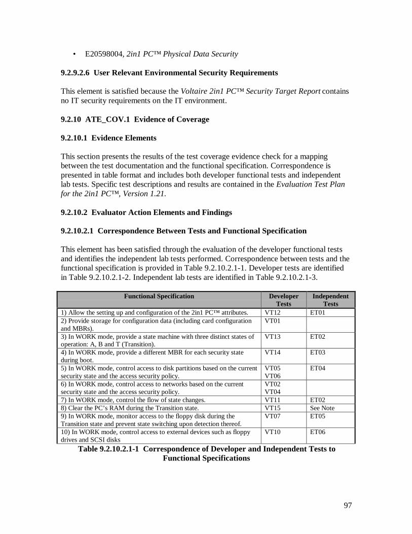
97
• E20598004, 2in1 PC™ Physical Data Security
9.2.9.2.6 User Relevant Environmental Security Requirements
This element is satisfied because the Voltaire 2in1 PC™ Security Target Report containsno IT security requirements on the IT environment.
9.2.10 ATE_COV.1 Evidence of Coverage
9.2.10.1 Evidence Elements
This section presents the results of the test coverage evidence check for a mappingbetween the test documentation and the functional specification. Correspondence ispresented in table format and includes both developer functional tests and independentlab tests. Specific test descriptions and results are contained in the Evaluation Test Planfor the 2in1 PC™ , Version 1.21.
9.2.10.2 Evaluator Action Elements and Findings
9.2.10.2.1 Correspondence Between Tests and Functional Specification
This element has been satisfied through the evaluation of the developer functional testsand identifies the independent lab tests performed. Correspondence between tests and thefunctional specification is provided in Table 9.2.10.2.1-1. Developer tests are identifiedin Table 9.2.10.2.1-2. Independent lab tests are identified in Table 9.2.10.2.1-3.
Functional Specification DeveloperTests
IndependentTests
1) Allow the setting up and configuration of the 2in1 PC™ attributes. VT12 ET012) Provide storage for configuration data (including card configurationand MBRs).
VT01
3) In WORK mode, provide a state machine with three distinct states ofoperation: A, B and T (Transition).
VT13 ET02
4) In WORK mode, provide a different MBR for each security stateduring boot.
VT14 ET03
5) In WORK mode, control access to disk partitions based on the currentsecurity state and the access security policy.
VT05VT06
ET04
6) In WORK mode, control access to networks based on the currentsecurity state and the access security policy.
VT02VT04
7) In WORK mode, control the flow of state changes. VT11 ET028) Clear the PC’s RAM during the Transition state. VT15 See Note9) In WORK mode, monitor access to the floppy disk during theTransition state and prevent state switching upon detection thereof.
VT07 ET05
10) In WORK mode, control access to external devices such as floppydrives and SCSI disks
VT10 ET06
Table 9.2.10.2.1-1 Correspondence of Developer and Independent Tests toFunctional Specifications
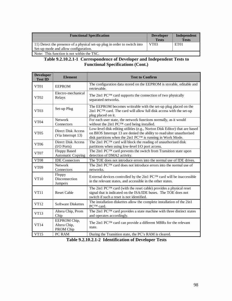
98
Functional Specification DeveloperTests
IndependentTests
11) Detect the presence of a physical set-up plug in order to switch intoSet-up mode and allow configuration.
VT03 ET01
Note: This function is not within the TSC.Table 9.2.10.2.1-1 Correspondence of Developer and Independent Tests to
Functional Specifications (Cont.)
DeveloperTest ID Element Test to Confirm
VT01 EEPROM The configuration data stored on the EEPROM is storable, editable andretrievable.
VT02Electro-mechanicalRelays The 2in1 PC™ card supports the connection of two physically
separated networks.
VT03 Set-up Plug The EEPROM becomes writeable with the set-up plug placed on the2in1 PC™ card. The card will allow full disk access with the set-upplug placed on it.
VT04 NetworkConnectors
For each user state, the network functions normally, as it wouldwithout the 2in1 PC™ card being installed.
VT05 Direct Disk Access(Via Interrupt 13)
Low-level disk editing utilities (e.g., Norton Disk Editor) that are basedon BIOS Interrupt 13 are denied the ability to read/alter unauthoriseddisk partitions when the 2in1 PC™ is running in Work Mode.
VT06 Direct Disk Access(I/O Ports)
The 2in1 PC™ card will block the reading of unauthorised diskpartitions when using low-level I/O port access.
VT07 Floppy BasedAutomatic Copying
The 2in1 PC™ card prevents the switch from Transition state upondetection of DMA2 activity.
VT08 IDE Connectors The TOE does not introduce errors into the normal use of IDE drives.
VT09 NetworkConnectors
The 2in1 PC™ card does not introduce errors into the normal use ofnetworks.
VT10FloppyDisconnectionJumpers
External devices controlled by the 2in1 PC™ card will be inaccessiblein the relevant states, and accessible in the other states.
VT11 Reset CableThe 2in1 PC™ card (with the reset cable) provides a physical resetsignal that is indicated on the ISA/IDE buses. The TOE does notswitch if such a reset is not identified.
VT12 Software Diskettes The installation diskettes allow the complete installation of the 2in1PC™ card.
VT13 Altera Chip, PromChip
The 2in1 PC™ card provides a state machine with three distinct statesand operates accordingly.
VT14EEPROM Chip,Altera Chip,PROM Chip
The 2in1 PC™ card can provide a different MBRs for the relevantstate.
VT15 PC RAM During the Transition state, the PC’s RAM is cleared.Table 9.2.10.2.1-2 Identification of Developer Tests
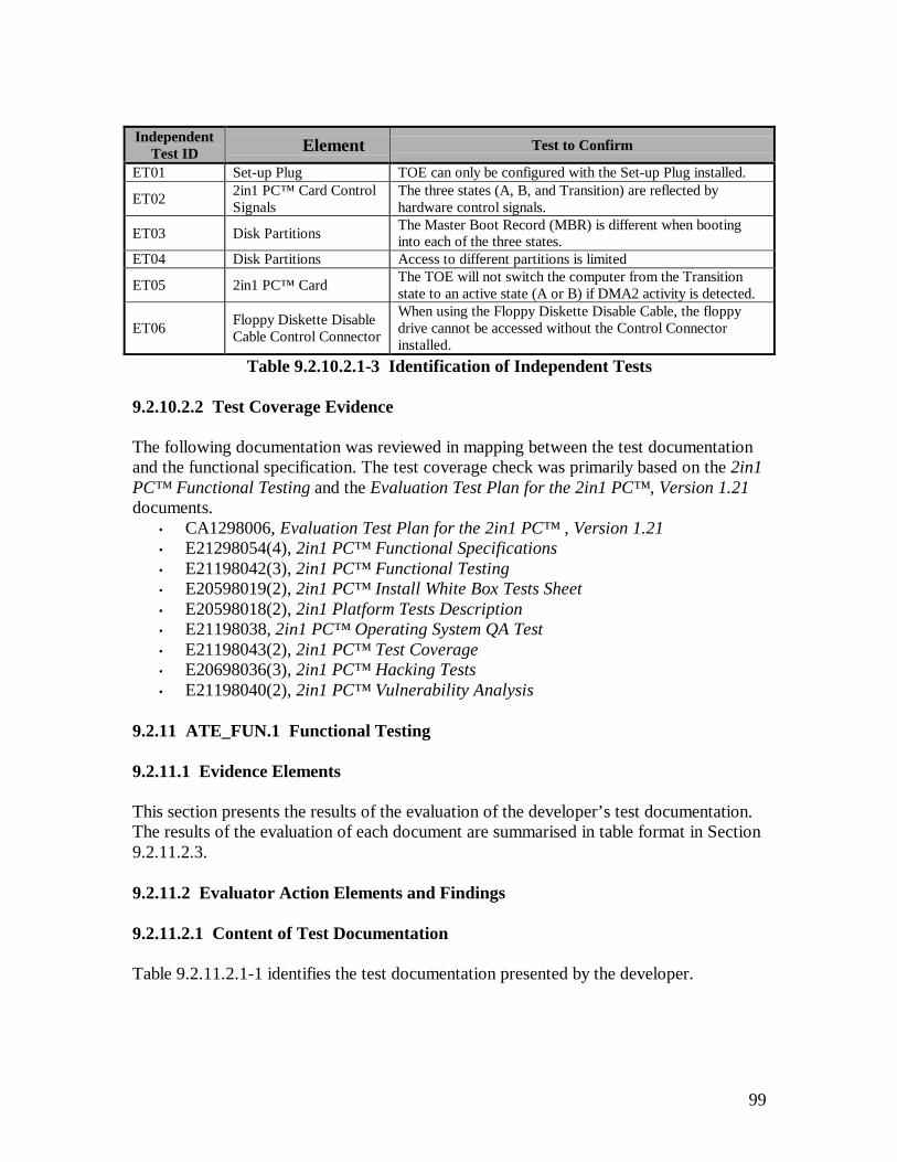
99
IndependentTest ID Element Test to Confirm
ET01 Set-up Plug TOE can only be configured with the Set-up Plug installed.
ET02 2in1 PC™ Card ControlSignals
The three states (A, B, and Transition) are reflected byhardware control signals.
ET03 Disk Partitions The Master Boot Record (MBR) is different when bootinginto each of the three states.
ET04 Disk Partitions Access to different partitions is limited
ET05 2in1 PC™ Card The TOE will not switch the computer from the Transitionstate to an active state (A or B) if DMA2 activity is detected.
ET06 Floppy Diskette DisableCable Control Connector
When using the Floppy Diskette Disable Cable, the floppydrive cannot be accessed without the Control Connectorinstalled.
Table 9.2.10.2.1-3 Identification of Independent Tests
9.2.10.2.2 Test Coverage Evidence
The following documentation was reviewed in mapping between the test documentationand the functional specification. The test coverage check was primarily based on the 2in1PC™ Functional Testing and the Evaluation Test Plan for the 2in1 PC™ , Version 1.21documents.
• CA1298006, Evaluation Test Plan for the 2in1 PC™ , Version 1.21• E21298054(4), 2in1 PC™ Functional Specifications• E21198042(3), 2in1 PC™ Functional Testing• E20598019(2), 2in1 PC™ Install White Box Tests Sheet• E20598018(2), 2in1 Platform Tests Description• E21198038, 2in1 PC™ Operating System QA Test• E21198043(2), 2in1 PC™ Test Coverage• E20698036(3), 2in1 PC™ Hacking Tests• E21198040(2), 2in1 PC™ Vulnerability Analysis
9.2.11 ATE_FUN.1 Functional Testing
9.2.11.1 Evidence Elements
This section presents the results of the evaluation of the developer’s test documentation. The results of the evaluation of each document are summarised in table format in Section9.2.11.2.3.
9.2.11.2 Evaluator Action Elements and Findings
9.2.11.2.1 Content of Test Documentation
Table 9.2.11.2.1-1 identifies the test documentation presented by the developer.
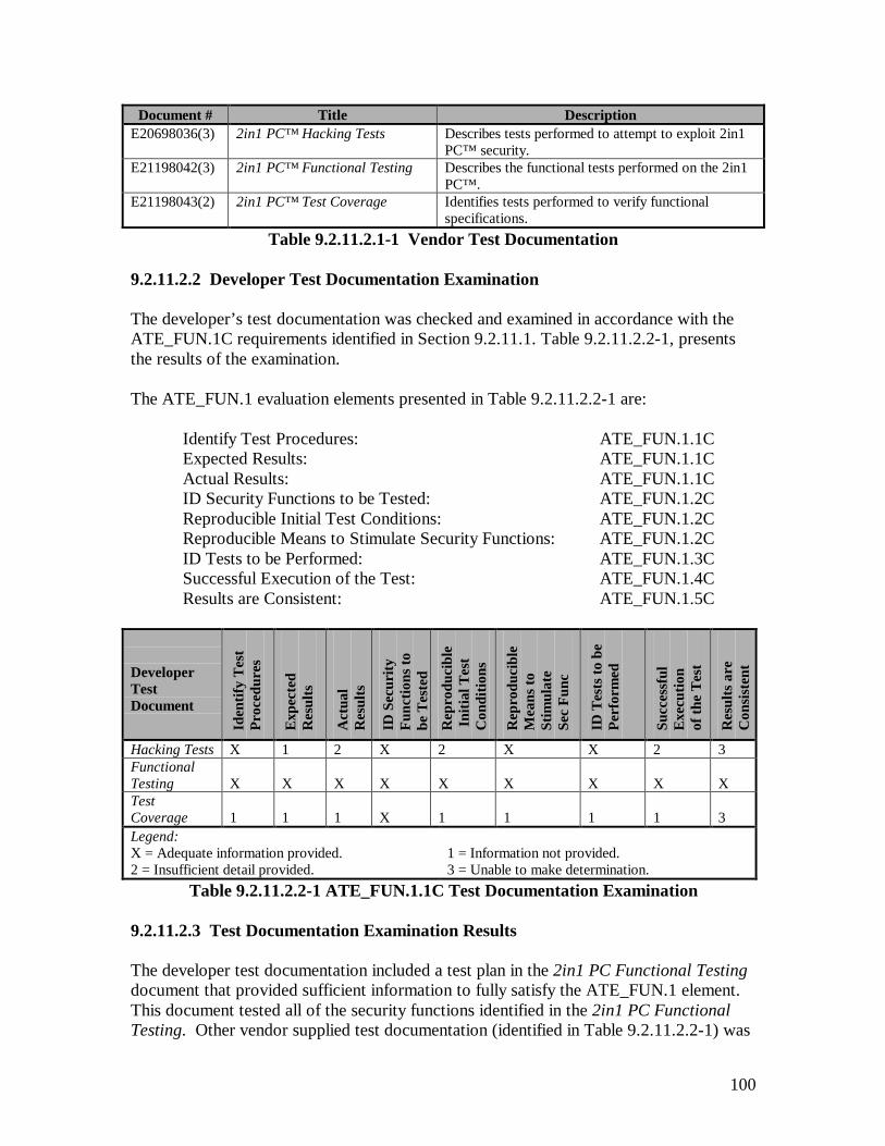
100
Document # Title DescriptionE20698036(3) 2in1 PC™ Hacking Tests Describes tests performed to attempt to exploit 2in1
PC™ security.E21198042(3) 2in1 PC™ Functional Testing Describes the functional tests performed on the 2in1
PC™ .E21198043(2) 2in1 PC™ Test Coverage Identifies tests performed to verify functional
specifications.Table 9.2.11.2.1-1 Vendor Test Documentation
9.2.11.2.2 Developer Test Documentation Examination
The developer’s test documentation was checked and examined in accordance with theATE_FUN.1C requirements identified in Section 9.2.11.1. Table 9.2.11.2.2-1, presentsthe results of the examination.
The ATE_FUN.1 evaluation elements presented in Table 9.2.11.2.2-1 are:
Identify Test Procedures: ATE_FUN.1.1CExpected Results: ATE_FUN.1.1CActual Results: ATE_FUN.1.1CID Security Functions to be Tested: ATE_FUN.1.2CReproducible Initial Test Conditions: ATE_FUN.1.2CReproducible Means to Stimulate Security Functions: ATE_FUN.1.2CID Tests to be Performed: ATE_FUN.1.3CSuccessful Execution of the Test: ATE_FUN.1.4CResults are Consistent: ATE_FUN.1.5C
DeveloperTestDocument
Iden
tify
Tes
tPr
oced
ures
Exp
ecte
dR
esul
ts
Act
ual
Res
ults
ID S
ecur
ityFu
nctio
ns to
be T
este
d
Rep
rodu
cibl
e I
nitia
l Tes
tC
ondi
tions
Rep
rodu
cibl
eM
eans
toSt
imul
ate
Sec
Func
ID T
ests
to b
ePe
rfor
med
Succ
essf
ulE
xecu
tion
of th
e T
est
Res
ults
are
Con
sist
ent
Hacking Tests X 1 2 X 2 X X 2 3FunctionalTesting X X X X X X X X XTestCoverage 1 1 1 X 1 1 1 1 3Legend:X = Adequate information provided.2 = Insufficient detail provided.
1 = Information not provided.3 = Unable to make determination.
Table 9.2.11.2.2-1 ATE_FUN.1.1C Test Documentation Examination
9.2.11.2.3 Test Documentation Examination Results
The developer test documentation included a test plan in the 2in1 PC Functional Testingdocument that provided sufficient information to fully satisfy the ATE_FUN.1 element.This document tested all of the security functions identified in the 2in1 PC FunctionalTesting. Other vendor supplied test documentation (identified in Table 9.2.11.2.2-1) was

101
not used to satisfy the ATE_FUN.1 element since these documents did not provide therequired content to test the TSF, however they were reviewed by the evaluators.
The 2in1 PC Functional Testing document clearly identifies the test approach and goalsin the introductory section and provides a detailed analysis near the end of the document.The content of this document was reviewed by the evaluators and a selection of tests wasmade to be verified in section 9.2.12 ATE_IND.2 Independent Testing – Sample.Furthermore, the Evaluation Test Plan for the 2in1 PC™ was created to satisfy theATE_IND.2 requirement. This document identifies the vendor tests that were selectedand independent tests developed by the evaluators to confirm the TSF enforcement.These two test suites were identified by the evaluators to verify the validity of thedeveloper’s functional testing and provide correspondence to the functionalspecifications. Voltaire provided detailed test procedures for functional tests that could bereplicated and verified by the evaluators, see Table 9.2.11.2.2-2. The second suite of testswas independently developed and performed by CAFÉ Lab evaluators, see Table9.2.11.2.2-3. All of the test descriptions and results are contained in the Evaluation TestPlan for the 2in1 PC™ , Version 1.21.
Developer Test ID Element Test to Confirm
VT01 EEPROM The configuration data stored on the EEPROM is storable,editable and retrievable.
VT02 Electro-mechanicalRelays
The 2in1 PC™ card supports the connection of twophysically separated networks.
VT03 Set-up Plug
The EEPROM becomes writeable with the set-up plugplaced on 2in1 PC™ card after the machine has been hardbooted. The card will allow full disk access with the set-upplug placed on it.
VT04 Network ConnectorsThe network connection for each user state (A,B,& T)functions normally, as it would without the 2in1 PC™ cardbeing installed.
VT05 Direct Disk Access(Via Interrupt 13)
Low-level disk editing utilities such as Norton Disk Editorthat are based on BIOS Interrupt 13 are denied the ability toread / alter unauthorised disk partitions when the TOE isrunning in Work Mode.
VT06 Direct Disk Access(I/O Ports)
The 2in1 PC™ card will block the reading of unauthoriseddisk partitions when using low-level I/O port access whenthe TOE is running in Work Mode.
VT07 Floppy BasedAutomatic Copying
The 2in1 PC™ card prevents the switch from Transitionstate upon detection of DMA2 activity.
VT08 IDE Connectors The TOE does not introduce errors into the normal use ofIDE drives.
Table 9.2.11.2.2-2 Developer Tests

102
Developer Test ID Element Test to Confirm
VT09 Network Connectors The 2in1 PC™ card does not introduce errors into thenormal use of networks.
VT10FloppyDisconnectionJumpers
External devices controlled by the 2in1 PC™ card will beinaccessible in the relevant states, and accessible in theother states.
VT11 Reset CableThe 2in1 PC™ card (with the reset cable) provides aphysical reset signal that is indicated on the ISA/IDE buses.The TOE does not switch if such a reset is not identified.
VT12 Software Diskettes The installation diskettes allow the complete installation ofthe 2in1 PC™ card.
VT13 Altera Chip, PromChip
The 2in1 PC™ card provides a state machine with threedistinct states and operates accordingly.
VT14EEPROM Chip,Altera Chip, PROMChip
The 2in1 PC™ card can provide a different MBRs for therelevant state.
VT15 PC RAM During the Transition state, the PC’s RAM is cleared.Table 9.2.11.2.2-2 Developer Tests (Cont.)
Independent Test ID Element Test to Confirm
ET01 Set-up Plug The TOE can only be configured with the Set-up Pluginstalled.
ET02 2in1 PC™ CardControl Signals
The three machine states (A, B, and Transition) arereflected by hardware control signals.
ET03 Disk Partitions The Master Boot Record (MBR) is different when bootinginto each of the three machine states.
ET04 Disk Partitions Access to disk partitions is limited.
ET05 2in1 PC™ CardThe TOE will not switch the computer from the Transitionstate to an active state (A or B) when DMA2 activity isdetected.
ET06Floppy DisketteDisable CableControl Connector
The floppy drive can only be accessed with the ControlConnector installed and the 2in1 PC™ card in theconfigured state.
Table 9.2.11.2.2-3 Independent Tests
9.2.12 ATE_IND.2 Independent Testing – Sample
9.2.12.1 Evidence Elements
This section addresses the independent testing performed by the evaluators. The testinghas been broken down into two test suites that are defined in the Evaluation Test Plan for2in1 PC™ , Version 1.2. The first test suite defines the replicated vendor tests that verifythe enforcement of the TSF, while the second test suite defines the independent testsperformed by the evaluators to verify the enforcement of the TSF.
103
9.2.12.2 Evaluator Action Elements and Findings
9.2.12.2.1 TOE Suitable for Testing
The TOE evaluated in this element was configured in accordance with the stated securityfunctions listed in the 2in1 PC™ Security Target. The details of this configuration aregiven in Section 2.2 of the Evaluation Test Plan for 2in1 PC™ , Version 1.21.Verification of the TOE’s suitability for testing was performed in the following manner:
1. After receiving the TOE from the vendor (ref. 9.2.2 ADO_DEL.1 DeliveryProcedures), verification of the configuration items was made. The details of thisverification are located in Section 9.2.1 ACM_CAP.2 Configuration Items.
2. The TOE was installed using only the vendor supplied product documentation.The details of this installation process are located in Section 9.2.3 ADO_IGS.1Installation, Generation, and Start-Up Procedures.
3. Resources used in the test were calibrated to ensure their proper operation. Alisting of the test resources used for the TOE evaluation is located in Section9.2.12.2.2 Equivalent Set of Resources, and also in Section 2 of the EvaluationTest Plan for 2in1 PC™ , Version 1.21.
After the steps listed above were completed, the enforcement of the settings configuredduring the installation procedure was verified. Verification was made by testing the diskaccess privileges and network connectivity for the Secure (A) and Public (B) machineoperating states. This was performed by creating a small text file, reading/writing the fileto other disk partitions and sending it to other PCs connected to the Secure (A) and Public(B) network connections. Once this process was completed and the enforcement of theTOE configuration settings was verified, the TOE was found to be suitable to commencethe vendor and evaluator tests defined in the Evaluation Test Plan for 2in1 PC™ , Version1.21.
9.2.12.2.2 Equivalent Set of Resources
The set of resources used during the execution of the vendor tests performed included thefollowing:
1. Twinbrook Systems, Intel 200Mhz Pentium-MMX – provided by the testing lab.Specific platform information is located in the Evaluation Test Plan for 2in1PC™ , Version 1.21.
2. Fluke 75 Multi-meter – provided by the testing lab to evaluate the networkconnectors for test VT03 in the Evaluation Test Plan for 2in1 PC™ , Version 1.21.
3. llr.exe – source code was provided by the vendor and then compiled by theevaluation lab to test the low-level read access to the hard disk based on Cylinder,
104
Head, Sector (CHS) and Logic Block Addressing (LBA) schemes. Thisapplication was used in test VT06 located in the Evaluation Test Plan for 2in1PC™ , Version 1.21.
4. rwe2.exe – source code was provided by the vendor and then compiled by theevaluation lab to test the read, write and execute permissions to the EEPROM onthe 2in1 PC™ card. This application was used in tests VT01 and VT03 located inthe Evaluation Test Plan for 2in1 PC™ , Version 1.21.
5. diskedit.exe (Norton) – provided by the vendor to read/write to specific addresseson the hard disk. This application was used in test VT05 (first and second sub-tests) located in the Evaluation Test Plan for 2in1 PC™ , Version 1.21.
The evaluators used the list of items above to verify the documented vendor test results.Most of the vendor performed tests were done so in a manner in which the scope waslarger (i.e. factors outside of the TSC were relied upon for the test results). The scope ofthe independent tests on the other hand, relied strictly upon the 2in1 PC™ card itself andits’ interfaces. Due to the differences in the scope, a subset of the vendor tests wasreplicated by the lab and the independent tests were used to verify the TOE securityfunctions defined in the 2in1 PC™ Security Target. The resources used in theindependent tests included the following:
1. Twinbrook Systems, Intel 200Mhz Pentium-MMX – provided by the testing lab.Specific platform information is located in the Evaluation Test Plan for 2in1PC™ , Version 1.21.
2. Innotec ID520 IDE Analyzer – provided by Voltaire. This device was used to intests ET03 and ET04 located in the Evaluation Test Plan for 2in1 PC™ , Version1.21 Plan.
3. Faxconn ISA Slot Extension Card – provided by Voltaire. This device was used inall of the independent tests to provide easy access to the 2in1 PC™ cardcomponents.
4. HP 545A Logic Probe – provided by Voltaire. This device was used inconjunction with the 2in1 PC™ Hardware Design document to verifyconnections on the 2in1 PC™ card. This device was used in independentevaluator tests as identified in the Evaluation Test Plan for 2in1 PC™ , Version1.21.
5. HP 1664A Logic Analyzer (50/100-MHz State/500-MHz Timing) – provided bythe testing lab. This device was used in test ET02 located in the Evaluation TestPlan for 2in1 PC™ , Version 1.21.
105
6. diskedit.exe (Norton) – provided by the vendor to read/write to specific addresseson the hard disk. This application was used in tests ET03 and ET04 located in theEvaluation Test Plan for 2in1 PC™ , Version 1.21.
The evaluators used the list of items above to execute the independent tests in order toevaluate the TOE at the interface level. The specific test details for the entire vendor andindependent tests performed are presented in Appendix A, B and C of the Evaluation TestPlan for 2in1 PC™ , Version 1.21.
Other applications installed on the system as part of the installation process (ref. 9.2.3ADO_IGS.1 Installation, Generation, and Start-Up Procedures) were also used during thevendor and independent testing. These applications were:
1. sense.exe – provided by installed files that were loaded onto the PC frominstallation disk 1. This application enables the Administrator to verify that theconfiguration settings stored on the EEPROM have not been modified. A value isdisplayed in hexadecimal and reflects the current configuration settings, thereforeany changes to the EEPROM’s configuration will result in a different value beingdisplayed. This application also displays the cards current working state (i.e.Secure (A), Public (B), or Transition).
2. report.exe – provided by installed files that were loaded onto the PC frominstallation disk 1. This application generates a report of the hard diskconfiguration (i.e. defining borders for each disk partition). This applicationworks in conjunction with report.bat.
3. report.bat – provided by installed files that were loaded onto the PC frominstallation disk 1. This application executes report.exe and redirects the output tothe display screen. This batch file was edited during the evaluation and renamedreport2.bat so that the output could be redirected to a file for printing. The outputof this file was used as a reference for other tests that were executed and is locatedafter test VT02 in the Evaluation Test Plan for 2in1 PC™ , Version 1.21.
9.2.12.2.3 Test a Subset of the TSF
The developer test documentation evidence was evaluated as to the relevance of theidentified security functions to be tested (ref. 9.2.11 ATE_FUN.1 Functional Testing).The selection of the developer tests was based upon a requirement to verify developerfunctional testing (see Section 9.2.11.2.3 Describe Scenarios) and correspondence to thetests mapped to the 2in1 PC™ Functional Specification. Once the test sample wasselected, independent tests were developed to further evaluate the security functions thatwere addressed by the developer test documentation (ref. 9.2.11 ATE_FUN.1 FunctionalTesting). With the confirmation of developer tests and the independent tests performedby the evaluators, every security function within the TSC has been tested. For the detailsof the testing coverage, refer to Table 9.2.10.2.1-1 Correspondence of Developer andIndependent Tests to Functional Specifications.

106
A selection of independent tests was also based on the identification of residual TOEvulnerabilities. After reviewing these vulnerabilities, the selection was made to beincluded as part of the independent tests. The specific details of these vulnerabilities aredefined in Section 9.2.14 AVA_VLA.1, Developer Vulnerability Analysis.
The independent tests were performed at the IDE interface level using an IDE analyzer.This test method was selected to capture all of the IDE bus traffic on both the controllerand hard disk side of the bus, thus allowing the ability to verify the card operatedaccording to its’ configured security state.
The identification and details for each of the evaluation tests performed is contained inthe Evaluation Test Plan for 2in1 PC™ , Version 1.21.
The expected results for all of the tests performed in the Evaluation Test Plan for 2in1PC™ , Version 1.21 were verified by the actual results. There were no inconsistenciesbetween the expected result and the actual results.
9.2.12.2.4 Verify Test Results for a Sample of Tests
This element addresses the scope of the documented vendor tests and provides a rationalefor the selection of specific vendor tests that were included in the Evaluation Test Planfor 2in1 PC™ , Version 1.21. The details of these procedures were documented by theevaluators and are located in Appendix A of the Evaluation Test Plan for 2in1 PC™ ,Version 1.21. The following vendor tests were selected to confirm their actual results:
1. VT01 – States that the configuration data on the EEPROM is storable, editableand retrievable. This test was selected to verify that the configuration data storedon the EEPROM could only be modified while the card is in set-up mode.Actual Result: The expected result was verified.
2. VT02 – States that the 2in1 PC™ card supports the connection of two physicallyseparated networks. This test was selected to verify:
a. When the PC is running in the Transition machine state, all networkconnections are severed.
b. When the PC is running in the Secure (A) machine state, connection is madeto only the Secure (A) network.
c. When the PC is running in the Public (B) machine state, connection is made toonly the Public (B) network.Actual Result: The expected result was verified.
3. VT03 – States that the EEPROM becomes writeable and full access to the harddisk is allowed when the PC is fully powered down, the set-up plug is installed onthe 2in1 PC™ card, and then the machine is powered back on. This test wasselected to verify that the detection of the installed set-up plug occurs after the PC

107
has been hard booted. Once this detection is made, the Administrator has theability to re-configure the EEPROM and also have full access to the hard disk.Actual Result: The expected result was verified.
4. VT04 – States that the connectivity to each of the two networks will functionnormally as it would without the 2in1 PC™ card being installed on the PC. Thistest was selected to verify that the 2in1 PC™ card supports the connection of twonetworks and that these networks are physically separated from one other. Thistest was also selected to verify that connectivity to each network is not affected asa result of having the 2in1 PC™ card installed on the machine (i.e. the card istransparent to the connected network).Actual Result: The expected result was verified.
5. VT05 – States that low-level disk editing utilities based on BIOS interrupt 13 aredenied the ability to read/alter unauthorised disk partitions when the TOE isrunning in work mode. This test was selected to verify that when the PC isrunning in any given machine state (Secure (A), Public (B), or Transition), accessto unauthorised disk partitions is blocked.Actual Result: The expected result was verified.
6. VT06 – States that the 2in1 PC™ card will block the reading of unauthorised diskpartitions when using low-level I/O port access methods while the TOE is runningin work mode. This test was selected to verify that when the PC is running in anygiven machine state (Secure (A), Public (B), or Transition), access tounauthorised disk partitions using LBA or CHS disk addressing methods will beblocked.Actual Result: The expected result was verified.
7. VT07 – States that the 2in1 PC™ card will prevent the switch from the Transitionmachine state upon detection of a floppy disk being accessed. This test wasselected to verify that the TOE monitors the ISA bus for any DMA2 traffic whilethe machine is running in the Transition machine state. If traffic is travelingacross the DMA2 channel, then the PC will not reboot into the Secure (A) orPublic (B) machine states; rather the PC will continue to reboot into theTransition state until no traffic is detected on the DMA2 channel.
Actual Result: The expected results were verified.
The vendor tests defined above were selected to verify that the key security functionsoffered by the TOE operated in accordance with the 2in1 PC™ Functional Specificationand the functional requirements listed in the 2in1 PC™ Security Target. Specifically, thekey security functions are three machine operating states (Secure (A), Public (B), andTransition), network access separation, hard disk access separation, and protection ofconfiguration information. Some of these key security functions, and also other securityfunctions offered by the TOE, have been further evaluated and defined in detail in theindependent tests described in Appendix B of the Evaluation Test Plan for 2in1 PC™ ,Version 1.21. The results of all of the independent tests performed were verified as

108
expected. Table 9.2.10.2.1-1 Correspondence of Developer and Independent Tests toFunctional Specification provides a mapping from the vendor and independent testsperformed to the 2in1 PC™ Functional Specification.
9.2.13 AVA_SOF.1 Strength of TOE Security Function Evaluation
9.2.13.1 Evidence Elements
This section addresses the strength of TOE security function, defining any mechanismsrelied upon by the TOE to enforce the TSF.
9.2.13.2 Evaluator Action Elements and Findings
9.2.13.2.1 Minimum Strength Level
This element is met because the TOE makes no strength of function claims.
9.2.13.2.2 Meets or Exceeds Claimed Strength of Function Metric
This element is met because the TOE makes no strength of function claims.
9.2.13.2.3 Confirm Correctness of Claimed Strength of Function
This element is met because the TOE makes no strength of function claims.
9.2.14 AVA_VLA.1 Developer Vulnerability Analysis
9.2.14.1 Evidence Elements
This section presents the results of the evaluation of the developer’s vulnerability analysisand penetration testing performed by the CAFÉ Lab. The attack potential for the TOE islow or higher based on the Voltaire 2in1 PC™ Security Target Report Secure UsageAssumptions and Organisational Security Policies (see Table 9.2.14.2-1 and Table9.2.14.2-2) and the identification and mitigation of obvious vulnerabilities in accordancewith AVA_VLA.1, Developer Vulnerability Analysis.
9.2.14.2 Evaluator Action Elements and Findings
9.2.14.2.1 Content of Developer’s Vulnerability Analysis
The 2in1 PC™ Vulnerability Analysis, E21198040(2), satisfies this element by providinga unique identification and description of each vulnerability along with a description ofhow each vulnerability is addressed by the TOE.
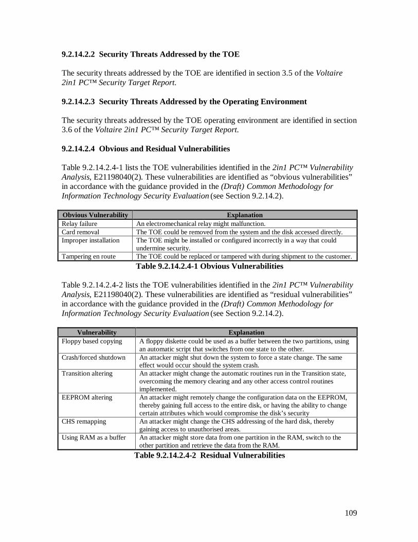
109
9.2.14.2.2 Security Threats Addressed by the TOE
The security threats addressed by the TOE are identified in section 3.5 of the Voltaire2in1 PC™ Security Target Report.
9.2.14.2.3 Security Threats Addressed by the Operating Environment
The security threats addressed by the TOE operating environment are identified in section3.6 of the Voltaire 2in1 PC™ Security Target Report.
9.2.14.2.4 Obvious and Residual Vulnerabilities
Table 9.2.14.2.4-1 lists the TOE vulnerabilities identified in the 2in1 PC™ VulnerabilityAnalysis, E21198040(2). These vulnerabilities are identified as “obvious vulnerabilities”in accordance with the guidance provided in the (Draft) Common Methodology forInformation Technology Security Evaluation (see Section 9.2.14.2).
Obvious Vulnerability ExplanationRelay failure An electromechanical relay might malfunction.Card removal The TOE could be removed from the system and the disk accessed directly.Improper installation The TOE might be installed or configured incorrectly in a way that could
undermine security.Tampering en route The TOE could be replaced or tampered with during shipment to the customer.
Table 9.2.14.2.4-1 Obvious Vulnerabilities
Table 9.2.14.2.4-2 lists the TOE vulnerabilities identified in the 2in1 PC™ VulnerabilityAnalysis, E21198040(2). These vulnerabilities are identified as “residual vulnerabilities”in accordance with the guidance provided in the (Draft) Common Methodology forInformation Technology Security Evaluation (see Section 9.2.14.2).
Vulnerability ExplanationFloppy based copying A floppy diskette could be used as a buffer between the two partitions, using
an automatic script that switches from one state to the other.Crash/forced shutdown An attacker might shut down the system to force a state change. The same
effect would occur should the system crash.Transition altering An attacker might change the automatic routines run in the Transition state,
overcoming the memory clearing and any other access control routinesimplemented.
EEPROM altering An attacker might remotely change the configuration data on the EEPROM,thereby gaining full access to the entire disk, or having the ability to changecertain attributes which would compromise the disk’s security
CHS remapping An attacker might change the CHS addressing of the hard disk, therebygaining access to unauthorised areas.
Using RAM as a buffer An attacker might store data from one partition in the RAM, switch to theother partition and retrieve the data from the RAM.
Table 9.2.14.2.4-2 Residual Vulnerabilities
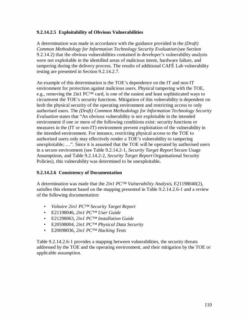
110
9.2.14.2.5 Exploitability of Obvious Vulnerabilities
A determination was made in accordance with the guidance provided in the (Draft)Common Methodology for Information Technology Security Evaluation (see Section9.2.14.2) that the obvious vulnerabilities contained in developer’s vulnerability analysiswere not exploitable in the identified areas of malicious intent, hardware failure, andtampering during the delivery process. The results of additional CAFÉ Lab vulnerabilitytesting are presented in Section 9.2.14.2.7.
An example of this determination is the TOE’s dependence on the IT and non-ITenvironment for protection against malicious users. Physical tampering with the TOE,e.g., removing the 2in1 PC™ card, is one of the easiest and least sophisticated ways tocircumvent the TOE’s security functions. Mitigation of this vulnerability is dependent onboth the physical security of the operating environment and restricting access to onlyauthorised users. The (Draft) Common Methodology for Information Technology SecurityEvaluation states that “An obvious vulnerability is not exploitable in the intendedenvironment if one or more of the following conditions exist: security functions ormeasures in the (IT or non-IT) environment prevent exploitation of the vulnerability inthe intended environment. For instance, restricting physical access to the TOE toauthorised users only may effectively render a TOE’s vulnerability to tamperingunexploitable; … ”. Since it is assumed that the TOE will be operated by authorised usersin a secure environment (see Table 9.2.14.2-1, Security Target Report Secure UsageAssumptions, and Table 9.2.14.2-2, Security Target Report Organisational SecurityPolicies), this vulnerability was determined to be unexploitable.
9.2.14.2.6 Consistency of Documentation
A determination was made that the 2in1 PC™ Vulnerability Analysis, E21198040(2),satisfies this element based on the mapping presented in Table 9.2.14.2.6-1 and a reviewof the following documentation:
• Voltaire 2in1 PC™ Security Target Report• E21198046, 2in1 PC™ User Guide• E21298063, 2in1 PC™ Installation Guide• E20598004, 2in1 PC™ Physical Data Security• E20698036, 2in1 PC™ Hacking Tests
Table 9.2.14.2.6-1 provides a mapping between vulnerabilities, the security threatsaddressed by the TOE and the operating environment, and their mitigation by the TOE orapplicable assumption.
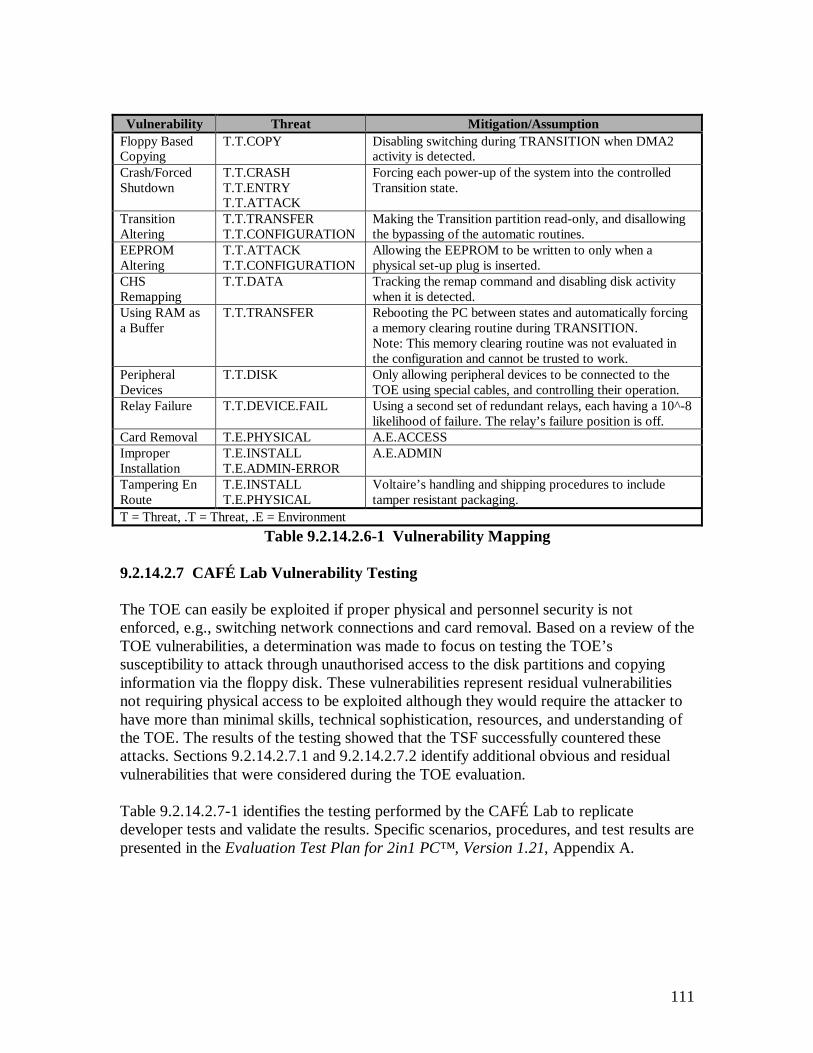
111
Vulnerability Threat Mitigation/AssumptionFloppy BasedCopying
T.T.COPY Disabling switching during TRANSITION when DMA2activity is detected.
Crash/ForcedShutdown
T.T.CRASHT.T.ENTRYT.T.ATTACK
Forcing each power-up of the system into the controlledTransition state.
TransitionAltering
T.T.TRANSFERT.T.CONFIGURATION
Making the Transition partition read-only, and disallowingthe bypassing of the automatic routines.
EEPROMAltering
T.T.ATTACKT.T.CONFIGURATION
Allowing the EEPROM to be written to only when aphysical set-up plug is inserted.
CHSRemapping
T.T.DATA Tracking the remap command and disabling disk activitywhen it is detected.
Using RAM asa Buffer
T.T.TRANSFER Rebooting the PC between states and automatically forcinga memory clearing routine during TRANSITION.Note: This memory clearing routine was not evaluated inthe configuration and cannot be trusted to work.
PeripheralDevices
T.T.DISK Only allowing peripheral devices to be connected to theTOE using special cables, and controlling their operation.
Relay Failure T.T.DEVICE.FAIL Using a second set of redundant relays, each having a 10^-8likelihood of failure. The relay’s failure position is off.
Card Removal T.E.PHYSICAL A.E.ACCESSImproperInstallation
T.E.INSTALLT.E.ADMIN-ERROR
A.E.ADMIN
Tampering EnRoute
T.E.INSTALLT.E.PHYSICAL
Voltaire’s handling and shipping procedures to includetamper resistant packaging.
T = Threat, .T = Threat, .E = EnvironmentTable 9.2.14.2.6-1 Vulnerability Mapping
9.2.14.2.7 CAFÉ Lab Vulnerability Testing
The TOE can easily be exploited if proper physical and personnel security is notenforced, e.g., switching network connections and card removal. Based on a review of theTOE vulnerabilities, a determination was made to focus on testing the TOE’ssusceptibility to attack through unauthorised access to the disk partitions and copyinginformation via the floppy disk. These vulnerabilities represent residual vulnerabilitiesnot requiring physical access to be exploited although they would require the attacker tohave more than minimal skills, technical sophistication, resources, and understanding ofthe TOE. The results of the testing showed that the TSF successfully countered theseattacks. Sections 9.2.14.2.7.1 and 9.2.14.2.7.2 identify additional obvious and residualvulnerabilities that were considered during the TOE evaluation.
Table 9.2.14.2.7-1 identifies the testing performed by the CAFÉ Lab to replicatedeveloper tests and validate the results. Specific scenarios, procedures, and test results arepresented in the Evaluation Test Plan for 2in1 PC™ , Version 1.21, Appendix A.
112
Element Test to Confirm VulnerabilityDirect Disk Access(Via Interrupt 13)VT05
Low-level disk editing utilities such as Norton DiskEditor that are based on BIOS Interrupt 13 are deniedthe ability to read / alter unauthorised disk partitionswhen the TOE is running in Work Mode.
An attacker might gainaccess to unauthoriseddisk partitions.
Direct Disk Access(I/O Ports)VT06
The 2in1 PC™ card will block the reading ofunauthorised disk partitions when using low-level I/Oport access.
An attacker might gainaccess to unauthoriseddisk partitions.
Floppy BasedAutomatic CopyingVT07
The 2in1 PC™ card prevents the switch from theTransition machine state upon detection of any DMA2activity.
A floppy diskette couldbe used as a bufferbetween the twopartitions, using anautomatic script thatswitches from one stateto the other.
VT [Number] = Vendor Test [Test Reference Number]Table 9.2.14.2.7-1 Sample Tests to Confirm Developer Vulnerability Test Results
Table 9.2.14.2.7-2 identifies the testing performed by the CAFÉ Lab to independentlyverify the mitigation of the unauthorised disk partition access and floppy disk copyingvulnerabilities. Specific scenarios, procedures, and test results are presented in theEvaluation Test Plan for 2in1 PC™ , Version 1, Appendix B.
Element Tests to Perform VulnerabilityET04 Access to the four disk partitions (Secure (A), Public (B),
Transition, and Functional) is controlled by the TSF.An attacker might gainaccess to unauthorised diskpartitions.
ET05 The TOE will not switch the computer from theTransition machine state to an active state (Secure (A) orPublic (B)) when DMA2 activity has been detected.
A floppy diskette could beused as a buffer between thetwo partitions, using anautomatic script that switchesfrom one state to the other.
ET [Number] = Evaluator Test [Test Reference Number]Table 9.2.14.2.7-2 TSF Tests to Confirm Mitigation of TOE Vulnerabilities
9.2.14.2.7.1 Obvious Vulnerabilities
Table 9.2.14.2.7.1-1 identifies obvious vulnerabilities considered as part of the TOEevaluation. It also identifies the mitigation for each vulnerability.
Obvious Vulnerability Mitigation1. Card removal. A.E.ACCESS
P.E.KNOWN2. Switch network connections. A.E.ACCESS
P.E.KNOWN3. Unauthorised use of the external set-up plug in conjunctionwith internal enabler plug.
A.E.ACCESSP.E.KNOWN
4. Unauthorised use of set-up plug A.E.ACCESSP.E.KNOWN
Table 9.2.14.2.7.1-1 Obvious Vulnerabilities

113
Obvious Vulnerability Mitigation5. Unauthorised modification of device control connectionjumpers.
A.E.ACCESSP.E.KNOWN
6. Unauthorised configuration of PC with more than 2 storagedevices to be controlled by the TOE (jumper connections).
A.E.ACCESSP.E.KNOWN
A = Assumption, P = Physical, .E = EnvironmentTable 9.2.14.2.7.1-1 Obvious Vulnerabilities (Cont.)
9.2.14.2.7.2 Residual Vulnerabilities
Table 9.2.14.2.7.2-2 identifies vulnerabilities requiring the attacker to have more thanminimal skills, technical sophistication, resources, and understanding of the TOE. It alsoidentifies the mitigation for each vulnerability.
Residual Vulnerability Mitigation1. Directly addressing the Alterachip and modifying theconfiguration settings derivedfrom the EEPROM during theboot/reboot process.
Making the Altera chip non-addressable mitigates this vulnerability.The EEPROM chip on the other hand does have a machine addressand the Altera chip controls the write access to it. Write access isonly granted when the machine is running in set-up mode by the set-up plug jumpering the write enable pins on the 2in1 PC™ card.
2. Deleting 2in1 PC™drivers/files stored in the A&Bmachine via networks to preventstate switching.
This vulnerability is not within the scope of the TSF, however it canlead to a denial of service attack preventing a user from switching toanother machine state (i.e. Secure (A) or Public (B)). Thisvulnerability does not undermine the security provided by the TOEand can be resolved by the administrator reinstalling the drivers/filesthat were removed.
3. Introduction of maliciouscode, e.g. B>F>A.
This vulnerability is not within the scope of the TSF, however it canlead to corruption of data controlled by the TOE. The operatingenvironment must address this vulnerability by having software,such as anti-virus programs, installed into the Transition diskpartition. By storing such software in this disk partition, wheneverthe machine boots into the Transition machine state, the anti-virussoftware is executed to scan the Functional disk partition to preventthe spread of malicious code to the other machine state (i.e. Secure(A) or Public (B)).
Table 9.2.14.2.7.2-2 Residual Vulnerabilities
114
SECTION 10
EVALUATORCOMMENTS/RECOMMENDATIONS
10 EVALUATOR COMMENTS/RECOMMENDATIONS
This section contains some brief comments on the evaluated product and the evaluationprocess.
10.1 PRODUCT ENVIRONMENT
The TOE is an effective product for its’ intended use. However, the requirement for asecure environment with non-malicious users can not be over stressed. The single largestvulnerability of the system is to a physical attack, where the network connections areswitched.
10.2 INDIVIDUAL IDENTIFICATION & AUTHENTICATION
In most environments it would seem prudent to provide one, or more, effective I&Amechanisms to use with the TOE. This could be done by a single product running in theTransition partition and state, identifying and authenticating each individual user beforeallowing them to do anything on the system. Another way would be to use an I&Amechanism with the operating system in each of the user states (i.e., A and B). A thirdmethod would be to use I&A mechanisms in both the Transition and user states.
10.3 USE OF THE CEM
The TOE evaluation process incorporated the guidance provided in the (Draft) CommonMethodology for Information Technology Security Evaluation, CEM-98-030, Version0.5, November 1998. The guidance in Part 2: Evaluation Methodology was especiallyuseful in defining the evaluation effort for achieving an EAL2 evaluation and inexplaining the required actions for each element. The document is still in draft status andwas only used as a guide. The evaluation was performed in accordance with therequirements in the Common Criteria for Information technology Security Evaluation,CCIB-98-028, Version 2.0, May 1998.

A-1
APPENDIX A
ACRONYMSA
ACC – Access control [family of requirements from the CC]ACF – Access control functions [family of requirements from the CC]ACM – Configuration management [class of assurance requirements from the CC]ADM – Administrator guidance [family of requirements from the CC]ADO – Delivery and operation [class of assurance requirements from the CC]ADV – Development [class of assurance requirements from the CC]AGD – Guidance [class of assurance requirements from the CC]
AMO – A MBR Open [When this option is on (default), read MBR requests forstate A return the MBR from address 0,0,1 of the hard disk]
ATE – Testing [class of assurance requirements from the CC]AVA – Vulnerability assessment [class of assurance requirements from the CC]
BBIOS – Basic Input/Output System
CCAP – Configuration management [family of requirements from the CC]CC – Common Criteria for Information Technology Security Evaluation (Version 2.0)CEM – Common Methodology for Information Technology Security Evaluation (Version0.5)CHS – Cylinder, Head, Sector [method to access the PC’s hard disk]CM – Configuration ManagementCOTS – Commercial-Off-The-ShelfCOV – Coverage [family of requirements from the CC]CPU – Central Processor UnitCRC – Cyclic Redundancy Check
DDEL – Delivery [family of requirements from the CC]DMA2 – Direct Memory Access/Addressing, Channel 2DRQ2 – An ISA bus signal for DMA2
EEAL – Evaluation Assurance LevelEAL2 – Evaluation Assurance Level 2 [Structurally Tested]EEPROM – Electronically Erasable Programmable Read-Only MemoryET – Evaluator Test

A-2
FFDP – User data protection [class of functional requirements from the CC]FIA – Identification and authentication [class of functional requirements from the CC]FLS – Fail secure [family of requirements from the CC]FMT – Security management [class of functional requirements from the CC]FPT – Protection of the TOE security functions [class of functional requirements fromthe CC]FSP – Functional specification [family of requirements from the CC]FUN – Functional tests [family of requirements from the CC]
GGUI – Graphical User InterfaceGUID – Globally Unique Identifier
HHD – Hard DiskHLD – High-level design [family of requirements from the CC]
II&A – Identification and AuthenticationI/O – Input/OutputIDE – Integrated Drive ElectronicsIGS – Installation, generation and start-up [family of requirements from the CC]IND – Independent testing [family of requirements from the CC]ISA – Industry Standard ArchitectureIT – Information TechnologyITC – Import from outside TSF control [family of requirements from the CC]
JK
LLBA – Logical Block Addressing [method to access the PC’s hard disk]Linux – UNIX operating system named after Linus Toralds
MMB – Megabyte(s)MBR – Master Boot RecordMHz – Mega-HertzMMX – Matrix Manipulation Extensions [Intel] + Multimedia ExtensionsMSA – Management of security attributes [family of requirements from the CC]MS-DOS – Microsoft – Disk Operating System
A-3
NNIC – Network Interface CardNSA – National Security AgencyNT – Microsoft – New Technology [Microsoft] operating system
O
PPC – Personal ComputerPC/AT – Personal Computer/Advanced Technology [IBM AT standard]PCB – Printed Circuit BoardPCI – Peripheral Component Interconnect/InterfacePP – Protection ProfilePROM – Programmable Read-Only Memory
QQA – Quality Assurance
RRAM – Random Access MemoryRCR – Representation Correspondence [family of requirements from the CC]RCV – Trusted Recovery [family of requirements from the CC]ROM – Read-Only Memory
SSCO – Santa Cruz Operation [UNIX operating system]SCSI – Small Computer Systems InterfaceSDRAM – Synchronous Dynamic Random Access MemorySF – Security FunctionSFP – Security Function PolicySMR – Security Management Roles [family of requirements from the CC]SOF – Strength of Function [family of requirements from the CC]SPM – Security Policy Model [family of requirements from the CC]ST – Security TargetSYD – 2in1 PC™ System Design Document
TTCP SYN – Transmission Control Protocol Synchronization Process [denial of serviceattack]TOE – Target of EvaluationTSC – TOE Scope Of ControlTSF – TOE Security FunctionTSFI – TOE Security Function InterfaceTSP – TOE Security Policy
UUID – User identification [family of requirements from the CC]USR – User guidance [family of requirements from the CC]

A-4
VVLA – Vulnerability analysis [family of requirements from the CC]VT – Vendor Test
WXYZ
B-1
APPENDIX B
Evaluation Test Plan for 2in1 PC, Version 1.21
Prepared for:Voltaire Advanced Data Security, Ltd.
103 Medinat HayehudimP.O.B. 12534
Herzylia 46733, Israel
By:COACT, Inc.
Rivers Ninety Five9140 Guilford Road, Suite LColumbia, Maryland 21046
Phone: 301-498-0150Fax: 301-498-0855
Email: café-lab@café.coact.com
Document No. CA129800607 January 1998

B-2
1 Introduction
This test plan identifies the tests performed for the 2in1 PC™ evaluation, describesspecific test scenarios and procedures, and presents the test results. It includes adescription of the test environment, test assumptions, and a cross-reference betweenspecific tests and the test results.
1.1 Scope
The 2in1 PC™ product evaluation is at the Evaluation Assurance Level 2 (EAL2). EAL2involves structural testing of the TOE but does not demand more effort on the part of thedeveloper than is consistent with good commercial practice and does not require asubstantially increased investment in cost or time. It is applicable where developers orusers require a low to moderate level of independently assured security in the absence ofready availability of the complete development record.
This test plan addresses the ATE_IND.2, Independent testing - sample, assurancecomponent of EAL2. The objective of this component is to demonstrate that the securityfunctions perform as specified. It requires the evaluator to repeat a sample of thedeveloper’s tests to gain confidence in the results obtained and to build on thedeveloper’s testing by conducting additional tests that exercise the TOE in a differentmanner.
The specific requirements of ATE_IND.2 are:
Dependencies:ADV_FSP.1 Informal functional specificationAGD_ADM.1 Administrative guidanceAGD_USR.1 User GuidanceATE_FUN.1 Functional testing
Developer action elements:ATE_IND.2.1D The developer shall provide the TOE for testing.
Content and presentation of evidence elements:ATE_IND.2.1C The TOE shall be suitable for testing.ATE_IND.2.2C The developer shall provide an equivalent set of resources to
those that were used in the developer’s functional testing of theTSF.
Evaluator action elements:ATE_IND.2.1E The evaluator shall confirm that the information provided meets
all requirements for content and presentation of evidence.ATE_IND.2.2E The evaluator shall test a subset of the TSF as appropriate to
confirm that the TOE operates as specified.
B-3
ATE_IND.2.3E The evaluator shall execute a sample of tests in the testdocumentation to verify the developer test results.
1.2 Functional Testing
Developer-provided information required by the ATE_FUN.1, Functional testing,assurance component has been evaluated separately and is not part of this test plan. Theevaluation methodology and results are detailed in the FER, Section 9.2.11.
1.3 Document Organization
The Evaluation Test Plan for the 2in1 PC, Version 1.21 is comprised of 5 Sections and 4Appendices.
Section 1, Introduction, provides the scope of the 2in1 PC™ product testing and thedocuments organization.
Section 2, Test Environment, describes the TOE configuration, the hardware andsoftware, and assumptions used during testing.
Section 3, Repeated Developer Tests to Confirm Developer Test Results, defines thesample of tests used to confirm the vendor test results and provides a mapping to the 2in1PC Functional Specification.
Section 4, Tests to Confirm the TOE Operates as Specified, defines the sample ofindependent tests used to confirm the 2in1 PC™ operates as specified and provides amapping to the 2in1 PC Functional Specification.
Section 5, Cross-Reference between Specific Tests and Test Results, defines the mappingbetween the tests listed in Sections 3 and 4 to their corresponding locations inAppendixes A and B and also defines the test document numbering scheme.
Appendix A, Test Results to Confirm Developer Test Results, this Section defines thefollowing for each test performed:
1) Naming the evaluators that performed the test.2) Identifying the date and time the test was performed.3) Provides a brief test description.4) Lists vendor documentation used as a reference.5) Defines any changes to the TOE configuration identified in Section.6) Identification of the expected test results.7) Identification of the actual test results.8) Identification of the repeatable test procedures.9) Evaluator details/observations noted during the test.
B-4
Appendix B, Test Results to Confirm the TOE Operates as Specified, this section definesthe following for each independent test performed:
1) Naming the evaluators that performed the test.2) Identifying the date and time the test was performed.3) Provides a brief test description.4) Lists vendor documentation used as a reference.5) Defines any changes to the TOE configuration identified in Section.6) Identification of the expected test results.7) Identification of the actual test results.8) Identification of the repeatable test procedures.9) Evaluator details/observations noted during the test.
Appendix C, Independent Evaluation Test Output, defines the complete output filesgenerated to confirm the TOE operates as specified in the Test Results confirmed inAppendix B.
Appendix D, References, defines the vendor documentation that was used during testing.

B-5
2 Test Environment
2.1 TOE
Voltaire 2in1 PC™ , Version 1.21 (For content version numbers, please refer to theVoltaire document titled “Configuration Items”). The 2in1 PC™ evaluation covers the2in1 PC™ ISA Slot PC card, network connections and peripheral device connectionscontrolled by the 2in1 PC™ card. These following items were tested:
1) The 2in1 PC™ ISA slot card was tested with an IDE analyzer to verify that itmonitors all IDE signals defined in the evaluation test documents in Appendix B.
2) The network connections were tested to verify that the two connections wereseparated and operated in accordance with the 2in1 PC Informal Security PolicyModel.
3) The jumpers on the 2in1 PC™ card were tested to verify the enabling/disablingof access to peripheral devices such as a floppy drive, SCSI connection, orparallel port connection for each machine state of operation, A and B.
4) The machine states were tested with a Logic Analyzer to verify that the bootablepartitions and network connections were enforced for the three operating states,Transition, Secure (A) and Public (B).
2.2 TOE Configuration
The 2in1 PC™ card was properly installed and configured in accordance with the stepsprovided in the 2in1 PC Installation Guide. The configuration settings made during thesesteps are defined in the following tables. Any changes to the specified settings are notedin the test results in Appendix A and B.
Partition Drive%
TotalMB
PrimaryMB
ExtendedMB
FileSystem
Access toFunctional
Functional 3 49 ---- ---- FAT ----Secure (A) 60 950 950 0 FAT Read OnlyPublic (B) 37 592 592 0 FAT Read/WriteTransition ---- 9 ---- ---- FAT No Access
Total: 100% 1600 MBTable 2-1 Partition Configuration
Transition Settings Advanced SettingsPower-Up Mode: Menu Reset Signal Advanced
Network Mode 2in1 PC2nd HD (if exists) A onlyForce Shutdown No
Table 2-2 Settings Configuration
2.3 System Hardware
Computer: Twinbrook Systems, Intel 200Mhz Pentium-MMXMotherboard: TX Chipset
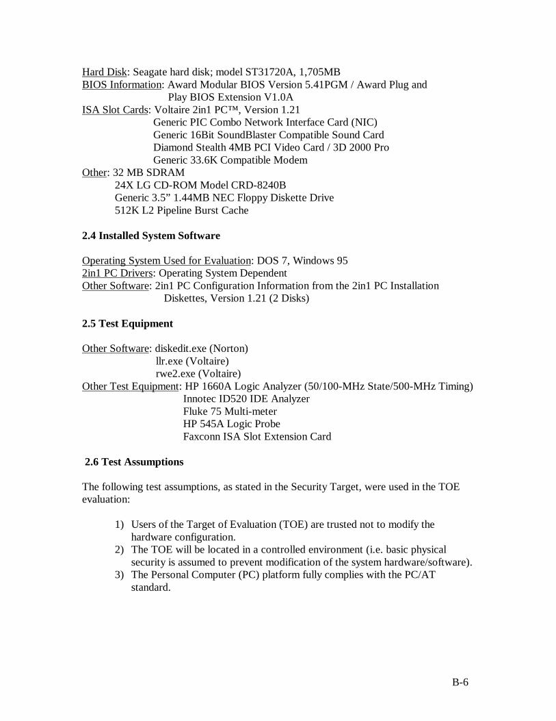
B-6
Hard Disk: Seagate hard disk; model ST31720A, 1,705MBBIOS Information: Award Modular BIOS Version 5.41PGM / Award Plug and
Play BIOS Extension V1.0AISA Slot Cards: Voltaire 2in1 PC™ , Version 1.21
Generic PIC Combo Network Interface Card (NIC) Generic 16Bit SoundBlaster Compatible Sound Card Diamond Stealth 4MB PCI Video Card / 3D 2000 Pro Generic 33.6K Compatible Modem
Other: 32 MB SDRAM24X LG CD-ROM Model CRD-8240BGeneric 3.5” 1.44MB NEC Floppy Diskette Drive512K L2 Pipeline Burst Cache
2.4 Installed System Software
Operating System Used for Evaluation: DOS 7, Windows 952in1 PC Drivers: Operating System DependentOther Software: 2in1 PC Configuration Information from the 2in1 PC Installation
Diskettes, Version 1.21 (2 Disks)
2.5 Test Equipment
Other Software: diskedit.exe (Norton) llr.exe (Voltaire)
rwe2.exe (Voltaire)Other Test Equipment: HP 1660A Logic Analyzer (50/100-MHz State/500-MHz Timing)
Innotec ID520 IDE Analyzer Fluke 75 Multi-meter HP 545A Logic Probe Faxconn ISA Slot Extension Card
2.6 Test Assumptions
The following test assumptions, as stated in the Security Target, were used in the TOEevaluation:
1) Users of the Target of Evaluation (TOE) are trusted not to modify thehardware configuration.
2) The TOE will be located in a controlled environment (i.e. basic physicalsecurity is assumed to prevent modification of the system hardware/software).
3) The Personal Computer (PC) platform fully complies with the PC/ATstandard.
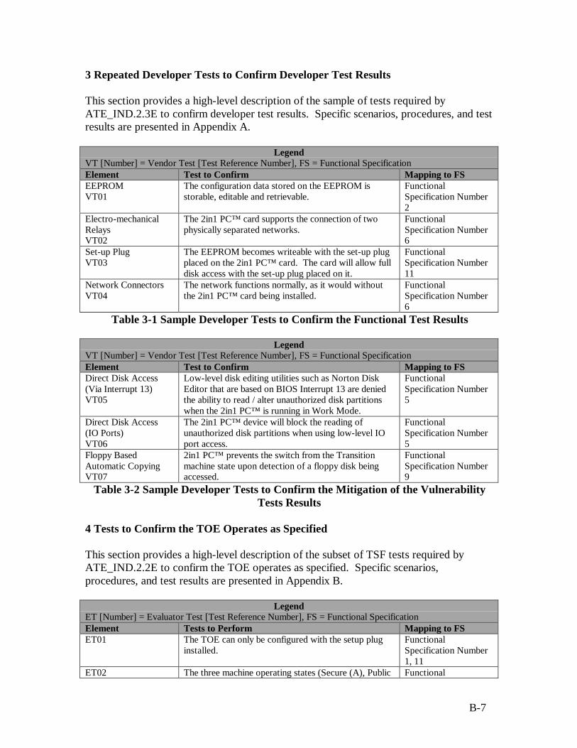
B-7
3 Repeated Developer Tests to Confirm Developer Test Results
This section provides a high-level description of the sample of tests required byATE_IND.2.3E to confirm developer test results. Specific scenarios, procedures, and testresults are presented in Appendix A.
LegendVT [Number] = Vendor Test [Test Reference Number], FS = Functional SpecificationElement Test to Confirm Mapping to FSEEPROMVT01
The configuration data stored on the EEPROM isstorable, editable and retrievable.
FunctionalSpecification Number2
Electro-mechanicalRelaysVT02
The 2in1 PC™ card supports the connection of twophysically separated networks.
FunctionalSpecification Number6
Set-up PlugVT03
The EEPROM becomes writeable with the set-up plugplaced on the 2in1 PC™ card. The card will allow fulldisk access with the set-up plug placed on it.
FunctionalSpecification Number11
Network ConnectorsVT04
The network functions normally, as it would withoutthe 2in1 PC™ card being installed.
FunctionalSpecification Number6
Table 3-1 Sample Developer Tests to Confirm the Functional Test Results
LegendVT [Number] = Vendor Test [Test Reference Number], FS = Functional SpecificationElement Test to Confirm Mapping to FSDirect Disk Access(Via Interrupt 13)VT05
Low-level disk editing utilities such as Norton DiskEditor that are based on BIOS Interrupt 13 are deniedthe ability to read / alter unauthorized disk partitionswhen the 2in1 PC™ is running in Work Mode.
FunctionalSpecification Number5
Direct Disk Access(IO Ports)VT06
The 2in1 PC™ device will block the reading ofunauthorized disk partitions when using low-level IOport access.
FunctionalSpecification Number5
Floppy BasedAutomatic CopyingVT07
2in1 PC™ prevents the switch from the Transitionmachine state upon detection of a floppy disk beingaccessed.
FunctionalSpecification Number9
Table 3-2 Sample Developer Tests to Confirm the Mitigation of the VulnerabilityTests Results
4 Tests to Confirm the TOE Operates as Specified
This section provides a high-level description of the subset of TSF tests required byATE_IND.2.2E to confirm the TOE operates as specified. Specific scenarios,procedures, and test results are presented in Appendix B.
LegendET [Number] = Evaluator Test [Test Reference Number], FS = Functional SpecificationElement Tests to Perform Mapping to FSET01 The TOE can only be configured with the setup plug
installed.FunctionalSpecification Number1, 11
ET02 The three machine operating states (Secure (A), Public Functional
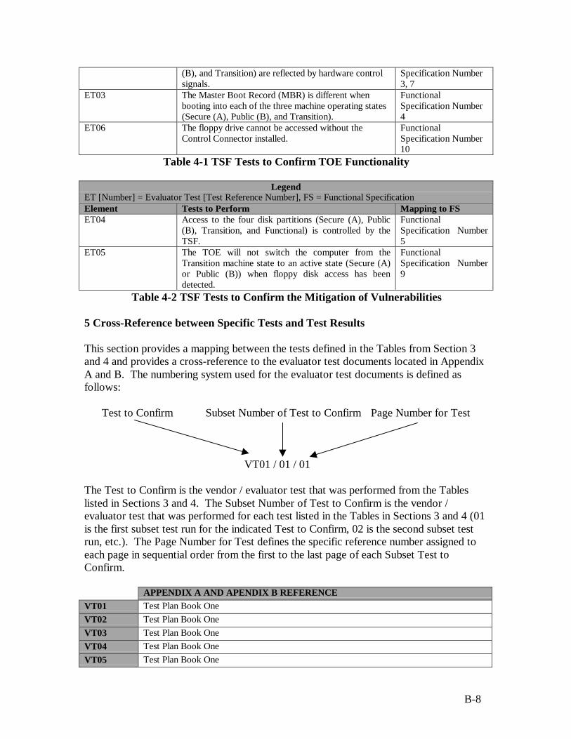
B-8
(B), and Transition) are reflected by hardware controlsignals.
Specification Number3, 7
ET03 The Master Boot Record (MBR) is different whenbooting into each of the three machine operating states(Secure (A), Public (B), and Transition).
FunctionalSpecification Number4
ET06 The floppy drive cannot be accessed without theControl Connector installed.
FunctionalSpecification Number10
Table 4-1 TSF Tests to Confirm TOE Functionality
LegendET [Number] = Evaluator Test [Test Reference Number], FS = Functional SpecificationElement Tests to Perform Mapping to FSET04 Access to the four disk partitions (Secure (A), Public
(B), Transition, and Functional) is controlled by theTSF.
FunctionalSpecification Number5
ET05 The TOE will not switch the computer from theTransition machine state to an active state (Secure (A)or Public (B)) when floppy disk access has beendetected.
FunctionalSpecification Number9
Table 4-2 TSF Tests to Confirm the Mitigation of Vulnerabilities
5 Cross-Reference between Specific Tests and Test Results
This section provides a mapping between the tests defined in the Tables from Section 3and 4 and provides a cross-reference to the evaluator test documents located in AppendixA and B. The numbering system used for the evaluator test documents is defined asfollows:
Test to Confirm Subset Number of Test to Confirm Page Number for Test
VT01 / 01 / 01
The Test to Confirm is the vendor / evaluator test that was performed from the Tableslisted in Sections 3 and 4. The Subset Number of Test to Confirm is the vendor /evaluator test that was performed for each test listed in the Tables in Sections 3 and 4 (01is the first subset test run for the indicated Test to Confirm, 02 is the second subset testrun, etc.). The Page Number for Test defines the specific reference number assigned toeach page in sequential order from the first to the last page of each Subset Test toConfirm.
APPENDIX A AND APENDIX B REFERENCEVT01 Test Plan Book OneVT02 Test Plan Book OneVT03 Test Plan Book OneVT04 Test Plan Book OneVT05 Test Plan Book One

B-9
VT06 Test Plan Book OneVT07 Test Plan Book OneET01 Test Plan Book One (Test Plan Books One – Five contain detailed output)ET02 Test Plan Book One (Test Plan Books One – Five contain detailed output)ET03 Test Plan Book One (Test Plan Books One – Five contain detailed output)ET04 Test Plan Book One (Test Plan Books One – Five contain detailed output)ET05 Test Plan Book One (Test Plan Books One – Five contain detailed output)ET06 Test Plan Book One (Test Plan Books One – Five contain detailed output)
C-1
APPENDIX C
BIBLIOGRAPHYThe following is a list of documents provided by the vendor in support of this evaluation(the numbering system used for each document is defined as, digits one and two representan EAL-2 level evaluation; digits three through six define the month and date thedocument was delivered to the evaluation lab; digits seven through nine define thespecific control number assigned to every document; and the bracketed numbers identifythe document as being revision one, revision two, and so on).
E20598004 – 2in1 PC™ Physical Data SecurityE20598005 – 2in1 PC™ Security ClaimsE20698006 – 2in1 PC™ Administrative RightsE20698007 – 2in1 PC™ Security PolicyE20698008 – 2in1 PC™ Flow PolicyE20698009 – 2in1 PC™ Hardware DesignE20698010 – 2in1 PC™ Terminal MapE20598011 – 2in1 PC™ Product Approval TestsE20598012(2) – 2in1 PC™ Software Design Document (Windows 3.11 – DOS)E20598013 – 2in1 PC™ Software Design Document (Windows NT)E20598014 – 2in1 PC™ Software Design Document (Windows 95)E21098015 – 2in1 PC™ Software Design Document (Windows 98)E21098016 – 2in1 PC™ System Development PlanE21098017 – 2in1 PC™ Platform Qualifications SummaryE20598018(2) – 2in1 PC™ Platform Tests DescriptionE20598019(2) – 2in1 PC™ Install White Box Tests SheetE20897020 – 2in1 PC™ Code DocumentationE20898021 – 2in1 PC™ Hardware FailureE20898022 – 2in1 PC™ New Version TestsE20398023 – 2in1 PC™ White PaperE20598024 – 2in1 PC™ System Design DocumentE20498025 – 2in1 PC™ SPOCK PresentationE20198034 – 2in1 PC™ IDE Tests – Source CodeE21198035(4) – 2in1 PC™ Informal Security Policy ModelE20698036(3) – 2in1 PC™ Hacking TestsE21198037 – Preliminary Evaluation of 2in1 PC™E21198038 – 2in1 PC™ Operating System QA TestE21198039(2) – Evaluation of 2in1 PC™ Installation Guide, Version 1.21E21198040(2) – 2in1 PC™ Vulnerability AnalysisE21198041(3) – 2in1 PC™ Configuration ItemsE21198042(3) – 2in1 PC™ Functional TestingE21198043(2) – 2in1 PC™ Tests CoverageE21197044 – 2in1 PC™ Product Requirements DocumentE21198045(3) – 2in1 PC™ Delivery Procedure
C-2
E21198046 – 2in1 PC™ User GuideE21198047(2) – 2in1 PC™ Mapping of Assurance ElementsE21198048 – 2in1 PC™ ClaimsE21198049 – 2in1 PC™ Relay InformationE21298050 – 2in1 PC™ Software ComponentsE21298053 – 2in1 PC™ Transition partitionE21298054(4) – 2in1 PC™ Functional SpecificationsE21298056 – 2in1 PC™ Addendum to the 2in1 PC™ – Installation SoftwareE21298057 – 2in1 PC™ IDE Tests – OutputE21298058 – 2in1 PC™ Addendum to the 2in1 PC™ – The Transition partitionE21298061 – 2in1 PC™ Updates to the SYD EEPROM Mapping SectionE21298062 – 2in1 PC™ Application NotesE21298063 – 2in1 PC™ Installation GuideE21298064 – 2in1 PC™ Quick Installation GuideE21197065 – 2in1 PC™ IO Protocol TestsE20199066 – 2in1 PC™ Addendum to the 2in1 PC™ – System Design Document
The following is a list of other documentation referenced in support of this evaluation:
CCIB-98-026 – Common Criteria for Information Technology Security Evaluation, Part1: Introduction and General Model, May 1998, Version 2.0.
CCIB-98-027 – Common Criteria for Information Technology Security Evaluation, Part2: Security Functional Requirements, May 1998, Version 2.0.
CCIB-98-027A – Common Criteria for Information Technology Security Evaluation,Part 2: Annexes, May 1998, Version 2.0.
CCIB-98-028 – Common Criteria for Information Technology Security Evaluation, Part3: Security Assurance Requirements, May 1998, Version 2.0.
CEM-98/030 – Common Criteria for Information Technology Security Evaluation, Part2: Evaluation Methodology, November 1998, Version 0.5.
Proposed TTAP Process for Common Criteria EAL1 & 2 Evaluations.