Embed Size (px)
Citation preview

CAD/CAM (SUBJECT CODE: 57024)
UNIT-1
INTRODUCTION
Learning Objectives:
Understand the various spheres of manufacturing activity where computers
are used
Differentiate between conventional and computer based manufacturing
system in product cycle
Explain CAD and its application
Explain various types of manufacturing organisations
Explain CAM and its application
COMPUTERS IN INDUSTRIAL MANUFACTURING
The role of computer in manufacturing may be broadly classified into two groups:
1. Computer monitoring and control of the manufacturing process.
2. Manufacturing support applications, which deal essentially with the
preparations for actual manufacturing and post-manufacture operations.
Second category: The types of support that can be envisaged are:
• Computer aided design and drafting,
• Computer aided engineering,
• Computer aided manufacturing,
• Computer aided process planning,
• Computer aided tool design,
• Computer aided NC part programming,
• Computer aided scheduling,
• Computer aided material requirement planning, etc.

OVERVIEW OF CAD/CAM
What is CAD?
CAD if often defined in a variety of ways and includes a large range of
activities. Very broadly it can be said to be the integration of computer
science (or software) techniques in engineering design. At one end when
we talk of modeling, iIt encompasses the following:
Use of computers (hardware & software) for designing products
Numerical method, optimizations etc.
2D/3D drafting
3D modeling for visualization
Modeling curves, surfaces, solids, mechanism, assemblies, etc.
The models thus developed are first visualized on display monitors
using avariety of techniques including wire frame displa, shaded image
display, hidden surface removed display and so on. Once the designer is
satisfied, these models are then used for various types of analysis /
applications. thus, at the other end it includes a number of analysis
activities. These could be:
Stress (or deflection) analysis, i.e. numerical methods meant for
estimating the behaviour of an artifact with respect to these
parameters. It includes tools like the Finite Element Method
(FEM).
Simulation of actual use
Optimization
Other applications like
o CAD/CAM integration
o Process planning
These are activities which normally use models developed using one or
more of the techniques mentioned above. These activities are often
included in other umbrellas like CAM or CAE. A term often used is
CAD to include this broad set of activities. They all use CAD models
and often the kind of application they have to be used ina determines the

kind of amodel to be developed. Hence, in this course I cover them
under the umbrella of CAD. In this course we will strive to give an
overview of modelling techniques followed by some applications,
specifically CAM.
Thus there are three aspects to CAD.
Modeling
Display/ Visualization
Applications
MODELING
Modelling typically includes a set of activities like
Defining objects
Defining relation between objects
Defining properties of objects
Defining the orientations of the objects in suitable co-ordinate
systems
Modification of existing definition (editing).
The figure below explains what a typical CAD model would need to
define, what kind of entities need to be defined and what relationships
exist between them.
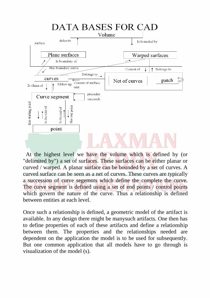
At the highest level we have the volume which is defined by (or
"delimited by") a set of surfaces. These surfaces can be either planar or
curved / warped. A planar surface can be bounded by a set of curves. A
curved surface can be seen as a net of curves. These curves are typically
a succession of curve segemnts which define the complete the curve.
The curve segment is defined using a set of end points / control points
which govern the nature of the curve. Thus a relationship is defined
between entities at each level.
Once such a relationship is defined, a geometric model of the artifact is
available. In any design there might be manysuch artifacts. One then has
to define properties of each of these artifacts and define a relationship
between them. The properties and the relationships needed are
dependent on the application the model is to be used for subsequently.
But one common application that all models have to go through is
visualization of the model (s).

COMPUTER AIDED MANUFACTURE (CAM)
Type of Production
1. Mass production - large lots e.g. automobiles
2. Batch production - medium lot sizes e.g. industrial machines,
aircrafts, etc.
3. Job shop production - small lots or one off, e.g. prototypes,
aircrafts,etc.
What are the advantages of using CAM?
• Greater design freedom:
Any changes that are required in design can be incorporated at
any design stage without worrying about any delays, since there would
hardly be any in an integrated CAM environment.
• Increased productivity:
In view of the fact that the total manufacturing activity is
completely organised through the computer, it would be possible to
increase the productivity of the plant.
• Greater operating flexibility:

CAM enhances the flexibility in manufacturing methods and
changing of product lines.
• Shorter lead-time:
Lead times in manufacturing would be greatly reduced.
• Improved reliability:
In view of the better manufacturing methods and controls at the
manufacturing stage, the products thus manufactured as well as of the
manufacturing system would be highly reliable.
• Reduced maintenance:
Since most of the components of a CAM system would include
integrated diagnostics and monitoring facilities, they would require less
maintenance compared to the conventional manufacturing methods.
• Reduced scrap and rework:
Because of the CNC machines used in production, and the part
programs being made by the stored geometry from the design stage, the
scrap level would be reduced to the minimum possible and almost no
rework would be necessary.
• Better management control:
As shown above, since all the information and controlling
functions are attempted with the help of the computer, a better
management control on the manufacturing activity is possible.
Application
Area
Software
Integrated
System
CAD-2D
drafting
CADCAM, AutoCAD, MicroCADM, VersaCAD
Pro/Engineer
Unigraphics
CATIA
CAD-Solid
modeling
Solid Edges, SolidWorks, SolidDesigner,
mechanical Desktop
I-DEAS
I/MES
EUCLID-IS
CAM
BravoNCG, VERICUT, DUCT, Camand,
Mastercam, Powermill
CAE
MSC/NASTRAN,ANSYS, PATRAN, DADS, C-
MOLDS,MOLDFLOW,MOLDEX, designWorks
PRODUCT CYCLE
Let us consider the manufacturing environment of a given product.
How does the product idea originate?
• The market forces determine the need for a product.
• Expertise on the part of the company estimates the likely demand and
probable profitability and decides on the best mode of designing and
manufacturing the desired product.
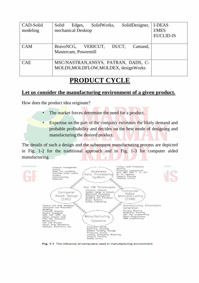
The details of such a design and the subsequent manufacturing process are depicted
in Fig. 1-2 for the traditional approach and in Fig. 1-3 for computer aided
manufacturing


Computer Aided Design (CAD)
Is a TOOL to aid designer/engineer
Classified under 2 categories:
1. Product Engineering
• Product functions
• Product Specifications
• Conceptual design
• Ergonomics and Aesthetics
• Standards
• Detailed Design
• Prototype development
• Testing
• Simulation
• Analysis
• Strength
• Kinematics, Dynamics
• Heat, Flow
• Design for Manufacture
• Design for Assembly
• Drafting
2. Manufacturing Engineering
• Process planning
• Process sheets
• Route sheets
• Tooling
• Cutting tools
• Jigs and Fixtures
• Dies and Moulds
• Manufacturing Information Generation
• CNC Part programmes
• Robot Programmes
• Inspection (CMM) programmes
• Production Organisation
• Bill of Materials
• Material Requirement Planning
• Production Planning
• Shop Floor Control
• Plant Simulation
• Marketing and Distribution

• Packaging
• Distribution, Marketing
Today’s CAD technology can provide the engineer/designer the necessary
help in the following ways:
1) Computer aided design (CAD) is faster and more accurate than conventional
methods.
2) The various construction facilities available in CAD would make the job of
developing the model and associated drafting a very easy task.
3) In contrast with the traditional drawing methods, under CAD it is possible to
manipulate various dimensions, attributes and distances of the drawing
elements. This quality makes CAD useful for design work.
4) Under CAD you will never have to repeat the design or drawing of any
component. Once a component has been made, it can be copied in all further
works within seconds, including any geometric transformation needed.
5) You can accurately calculate the various geometric properties including
dimensions of various components interactively in CAD, without actually
making their models and profiles.
6) 6. Modification of a model is very easy and would make the designer’s
7) task of improving a given product simple to take care of any future
8) requirements.
9) 7. Use of standard components (part libraries) makes for a very fast
10) model development work. Also a large number of components and
11) sub-assemblies may be stored in part libraries to be reproduced and
12) used later.
13) 8. Several professional CAD packages provide 3D (3 dimensional)
14) visualisation capabilities so that the designers can see the products
15) being designed from several different orientations. This eliminates
16) the need of making models of products for realisation and explaining
17) the concepts to the team.
18) Not only this, several designers can work simultaneously on the
19) same product and can gradually build the product in a modular fashion.
20) This certainly provides the answer to the need of today’s industry and the
21) one emerging on the horizon.
CAD/CAM HARDWARE
Computer System
Mainframe Computer and Graphics Terminals
Powerful
Inconvenient
High cost
Turn-key CAD System
Dedicated computer systems for CAD applications, cons super-
minicomputer and several design work stations.
Following the "central control concept"
Inconvenient and not powerful enough for complex 3D m
Workstations & High-End Personal Computers
Supporting multiple tasks
Supporting network and file-sharing – convenient
Low costs
Present and trend BASIC STRUCTURE OF COMPUTERS
Computer types: -
A computer can be defined as a fast electronic calculating machine that
accepts the (data) digitized input information process it as per the list of internally
stored instructions and produces the resulting information.
List of instructions are called programs & internal storage is called
computer memory.
The different types of computers are
Personal computers: - This is the most common type found in homes,
schools, Business offices etc., It is the most common type of desk top
computers with processing and storage units along with various input and
output devices. Note book computers: - These are compact and portable versions of PC Work stations: - These have high resolution input/output (I/O) graphics

capability, but with same dimensions as that of desktop computer. These are
used in engineering applications of interactive design work. Enterprise systems: - These are used for business data processing in
medium to large corporations that require much more computing power and
storage capacity than work stations. Internet associated with servers have
become a dominant worldwide source of all types of information.
Super computers: - These are used for large scale numerical calculations
required in the applications like weather forecasting etc.,
Functional unit: - A computer consists of five functionally independent main parts input,
memory, arithmetic logic unit (ALU), output and control unit.
Input ALU
I/O Memory Processor
Output Control Unit
Fig a : Functional units of computer
Input device accepts the coded information as source program i.e. high level
language. This is either stored in the memory or immediately used by the processor
to perform the desired operations. The program stored in the memory determines the
processing steps. Basically the computer converts one source program to an object
program. i.e. into machine language.
Finally the results are sent to the outside world through output device. All of
these actions are coordinated by the control unit.
Input unit: - The source program/high level language program/coded information/simply
data is fed to a computer through input devices keyboard is a most common type.
Whenever a key is pressed, one corresponding word or number is translated into its equivalent binary code over a cable & fed either to memory or processor.
Joysticks, trackballs, mouse, scanners etc are other input devices.

Memory unit: - Its function into store programs and data. It is basically to two types
1. Primary memory
2. Secondary memory
1. Primary memory: - Is the one exclusively associated with the processor and
operates at the electronics speeds programs must be stored in this memory while
they are being executed. The memory contains a large number of semiconductors
storage cells. Each capable of storing one bit of information. These are processed in
a group of fixed site called word.
To provide easy access to a word in memory, a distinct address is associated
with each word location. Addresses are numbers that identify memory location.
Number of bits in each word is called word length of the computer. Programs must reside in the memory during execution. Instructions and data can be
written into the memory or read out under the control of processor.
Memory in which any location can be reached in a short and fixed amount
of time after specifying its address is called random-access memory (RAM).
The time required to access one word in called memory access time.
Memory which is only readable by the user and contents of which can’t be altered is
called read only memory (ROM) it contains operating system.
Caches are the small fast RAM units, which are coupled with the processor
and are aften contained on the same IC chip to achieve high performance. Although
primary storage is essential it tends to be expensive.
2 Secondary memory: - Is used where large amounts of data & programs have to
be stored, particularly information that is accessed infrequently. Examples: - Magnetic disks & tapes, optical disks (ie CD-ROM’s), floppies etc.,
Arithmetic logic unit (ALU):- Most of the computer operators are executed in ALU of the processor like
addition, subtraction, division, multiplication, etc. the operands are brought into the ALU from memory and stored in high speed storage elements called register. Then
according to the instructions the operation is performed in the required sequence.
The control and the ALU are may times faster than other devices connected
to a computer system. This enables a single processor to control a number of external devices such as key boards, displays, magnetic and optical disks, sensors
and other mechanical controllers.

Output unit:- These actually are the counterparts of input unit. Its basic function is to send
the processed results to the outside world.
Examples:- Printer, speakers, monitor etc.
Control unit:- It effectively is the nerve center that sends signals to other units and senses
their states. The actual timing signals that govern the transfer of data between input unit, processor, memory and output unit are generated by the control unit.
Basic operational concepts: - To perform a given task an appropriate program consisting of a list of
instructions is stored in the memory. Individual instructions are brought from the
memory into the processor, which executes the specified operations. Data to be
stored are also stored in the memory.
Examples: - Add LOCA, R0
This instruction adds the operand at memory location LOCA, to operand in
register R0 & places the sum into register. This instruction requires the performance of several steps,
1. First the instruction is fetched from the memory into the processor.
2. The operand at LOCA is fetched and added to the contents of R0
3. Finally the resulting sum is stored in the register R0
The preceding add instruction combines a memory access operation with an
ALU Operations. In some other type of computers, these two types of operations are
performed by separate instructions for performance reasons. Load LOCA, R1 Add R1, R0
Transfers between the memory and the processor are started by sending the
address of the memory location to be accessed to the memory unit and issuing the appropriate control signals. The data are then transferred to or from the memory.

MEMORY
MAR MDR
CONTROL
PC R0
R1
…
ALU
…
IR …
…
Rn-1
n- GPRs
Fig b : Connections between the processor and the memory
The fig shows how memory & the processor can be connected. In addition
to the ALU & the control circuitry, the processor contains a number of registers used for several different purposes.
The instruction register (IR):- Holds the instructions that is currently being
executed. Its output is available for the control circuits which generates the timing
signals that control the various processing elements in one execution of instruction.
The program counter PC:-

This is another specialized register that keeps track of execution of a program. It contains the memory address of the next instruction to be fetched and executed.
Besides IR and PC, there are n-general purpose registers R0 through
Rn-1. The other two registers which facilitate communication with memory are: -
1. MAR – (Memory Address Register):- It holds the address of the location to
be accessed. 2. MDR – (Memory Data Register):- It contains the data to be written into or
read out of the address location.
Operating steps are 1. Programs reside in the memory & usually get these through the I/P unit. 2. Execution of the program starts when the PC is set to point at the first
instruction of the program. 3. Contents of PC are transferred to MAR and a Read Control Signal is sent to
the memory. 4. After the time required to access the memory elapses, the address word is
read out of the memory and loaded into the MDR. 5. Now contents of MDR are transferred to the IR & now the instruction is
ready to be decoded and executed. 6. If the instruction involves an operation by the ALU, it is necessary to obtain
the required operands. 7. An operand in the memory is fetched by sending its address to MAR &
Initiating a read cycle. 8. When the operand has been read from the memory to the MDR, it is
transferred from MDR to the ALU. 9. After one or two such repeated cycles, the ALU can perform the desired
operation. 10. If the result of this operation is to be stored in the memory, the result is sent
to MDR. 11. Address of location where the result is stored is sent to MAR & a write cycle
is initiated. 12. The contents of PC are incremented so that PC points to the next instruction
that is to be executed.
Normal execution of a program may be preempted (temporarily interrupted)
if some devices require urgent servicing, to do this one device raises an Interrupt signal.
An interrupt is a request signal from an I/O device for service by the
processor. The processor provides the requested service by executing an appropriate interrupt service routine.
The Diversion may change the internal stage of the processor its state must

be saved in the memory location before interruption. When the interrupt-routine
service is completed the state of the processor is restored so that the interrupted
program may continue.
Bus structure: - The simplest and most common way of interconnecting various parts of the
computer. To achieve a reasonable speed of operation, a computer must be organized
so that all its units can handle one full word of data at a given time.
A group of lines that serve as a connecting port for several devices is called
a
bus.
In addition to the lines that carry the data, the bus must have lines for
address and control purpose.
Simplest way to interconnect is to use the single bus as shown
Since the bus can be used for only one transfer at a time, only two units can
actively use the bus at any given time. Bus control lines are used to arbitrate
multiple requests for use of one bus.
Single bus structure is
Low cost
Very flexible for attaching peripheral devices

Multiple bus structure certainly increases, the performance but also increases the cost significantly.
All the interconnected devices are not of same speed & time, leads to a bit of a problem. This is solved by using cache registers (ie buffer registers). These
buffers are electronic registers of small capacity when compared to the main memory but of comparable speed.
The instructions from the processor at once are loaded into these buffers and then the complete transfer of data at a fast rate will take place.
Performance: - The most important measure of the performance of a computer is how
quickly it can execute programs. The speed with which a computer executes
program is affected by the design of its hardware. For best performance, it is necessary to design the compiles, the machine instruction set, and the hardware in a
coordinated way.
The total time required to execute the program is elapsed time is a measure
of the performance of the entire computer system. It is affected by the speed of the processor, the disk and the printer. The time needed to execute a instruction is called
the processor time.
Just as the elapsed time for the execution of a program depends on all units
in a computer system, the processor time depends on the hardware involved in the execution of individual machine instructions. This hardware comprises the processor
and the memory which are usually connected by the bus as shown in the fig c.
Cache
Main Processor
Memory
Memory
Bus
Fig d :The processor cache
The pertinent parts of the fig. c is repeated in fig. d which includes the cache
memory as part of the processor unit.
Let us examine the flow of program instructions and data between the
memory and the processor. At the start of execution, all program instructions and the
required data are stored in the main memory. As the execution proceeds, instructions

are fetched one by one over the bus into the processor, and a copy is placed in the
cache later if the same instruction or data item is needed a second time, it is read
directly from the cache.
The processor and relatively small cache memory can be fabricated on a single IC chip. The internal speed of performing the basic steps of instruction
processing on chip is very high and is considerably faster than the speed at which the instruction and
data can be fetched from the main memory. A program will be executed faster if the movement of instructions and data between the main memory and the processor is
minimized, which is achieved by using the cache.
For example:- Suppose a number of instructions are executed repeatedly over a short period of time as happens in a program loop. If these instructions are available in the
cache, they can be fetched quickly during the period of repeated use. The same applies to the data that are used repeatedly.
Processor clock: - Processor circuits are controlled by a timing signal called clock. The clock
designer the regular time intervals called clock cycles. To execute a machine
instruction the processor divides the action to be performed into a sequence of basic
steps that each step can be completed in one clock cycle. The length P of one clock
cycle is an important parameter that affects the processor performance.
Processor used in today’s personal computer and work station have a clock
rates that range from a few hundred million to over a billion cycles per second.
Basic performance equation: - We now focus our attention on the processor time component of the total
elapsed time. Let ‘T’ be the processor time required to execute a program that has
been prepared in some high-level language. The compiler generates a machine language object program that corresponds to the source program. Assume that complete execution of
the program requires the execution of N machine cycle language instructions. The number N is the actual number of instruction execution and is not necessarily equal
to the number of machine cycle instructions in the object program. Some instruction
may be executed more than once, which in the case for instructions inside a program loop others may not be executed all, depending on the input data used.
Suppose that the average number of basic steps needed to execute one
machine cycle instruction is S, where each basic step is completed in one clock cycle. If clock
rate is ‘R’ cycles per second, the program execution time is given by
N S T

R this is often referred to as the basic performance equation.
We must emphasize that N, S & R are not independent parameters changing
one may affect another. Introducing a new feature in the design of a processor will lead to improved performance only if the overall result is to reduce the value of T.
Pipelining and super scalar operation: - We assume that instructions are executed one after the other. Hence the
value of S is the total number of basic steps, or clock cycles, required to execute one instruction. A substantial improvement in performance can be achieved by overlapping the execution of successive instructions using a technique called pipelining.
Consider Add R1 R2 R3
This adds the contents of R1 & R2 and places the sum into R3.
The contents of R1 & R2 are first transferred to the inputs of ALU. After the
addition operation is performed, the sum is transferred to R3. The processor can read the next instruction from the memory, while the addition operation is being performed. Then of that instruction also uses, the ALU, its operand can be transferred to the ALU inputs at the same time that the add instructions is being
transferred to R3.
In the ideal case if all instructions are overlapped to the maximum degree
possible the execution proceeds at the rate of one instruction completed in each
clock cycle. Individual instructions still require several clock cycles to complete.
But for the purpose of computing T, effective value of S is 1.
A higher degree of concurrency can be achieved if multiple instructions
pipelines are implemented in the processor. This means that multiple functional
units are used creating parallel paths through which different instructions can be
executed in parallel with such an arrangement, it becomes possible to start the
execution of several instructions in every clock cycle. This mode of operation is
called superscalar execution. If it can be sustained for a long time during program
execution the effective value of S can be reduced to less than one. But the parallel
execution must preserve logical correctness of programs, that is the results produced
must be same as those produced by the serial execution of program instructions.
Now a days may processor are designed in this manner. Clock rate:- These are two possibilities for increasing the clock rate ‘R’.
1. Improving the IC technology makes logical circuit faster, which reduces the
time of execution of basic steps. This allows the clock period P, to be reduced and the clock rate R to be increased.
2. Reducing the amount of processing done in one basic step also makes it

possible to reduce the clock period P. however if the actions that have to be
performed by an instructions remain the same, the number of basic steps
needed may increase.
Increase in the value ‘R’ that are entirely caused by improvements in IC
technology affects all aspects of the processor’s operation equally with the
exception of the time it takes to access the main memory. In the presence of cache the percentage of accesses to the main memory is small. Hence much of the performance gain excepted from the use of faster technology can be realized.
Instruction set CISC & RISC:- Simple instructions require a small number of basic steps to execute.
Complex instructions involve a large number of steps. For a processor that has only simple
instruction a large number of instructions may be needed to perform a given
programming task. This could lead to a large value of ‘N’ and a small value of ‘S’
on the other hand if individual instructions perform more complex operations, a fewer instructions will be needed, leading to a lower value of N and a larger value of S. It is not obvious if one choice is better than the other.
But complex instructions combined with pipelining (effective value of S 1)
would achieve one best performance. However, it is much easier to implement
efficient pipelining in processors with simple instruction sets.
Performance measurements:- It is very important to be able to access the performance of a computer,
comp designers use performance estimates to evaluate the effectiveness of new features.
The previous argument suggests that the performance of a computer is given
by the execution time T, for the program of interest.
Inspite of the performance equation being so simple, the evaluation of ‘T’ is
highly complex. Moreover the parameters like the clock speed and various
architectural features are not reliable indicators of the expected performance.
Hence measurement of computer performance using bench mark programs
is done to make comparisons possible, standardized programs must be used.
The performance measure is the time taken by the computer to execute a given bench mark. Initially some attempts were made to create artificial programs
that could be used as bench mark programs. But synthetic programs do not properly predict the performance obtained when real application programs are run.

A nonprofit organization called SPEC- system performance evaluation
corporation selects and publishes bench marks.
The program selected range from game playing, compiler, and data base applications to numerically intensive programs in astrophysics and quantum
chemistry. In each case, the program is compiled under test, and the running time on a real computer is measured. The same program is also compiled and run on one
computer selected as reference.
The ‘SPEC’ rating is computed as follows.
Running time on the reference computer
SPEC rating =
Running time on the computer under test
If the SPEC rating = 50
Means that the computer under test is 50 times as fast as the ultra sparc 10. This is repeated for all the programs in the SPEC suit, and the geometric mean of the
result is computed.
Let SPECi be the rating for program ‘i’ in the suite. The overall SPEC
rating for the computer is given by 1
n
n
SPEC rating = SPECi
i 1
Where ‘n’ = number of programs in suite.
Since actual execution time is measured the SPEC rating is a measure of the combined effect of all factors affecting performance, including the compiler, the OS,
the processor, the memory of comp being tested.
Multiprocessor & microprocessors:- Large computers that contain a number of processor units are called
multiprocessor system.
These systems either execute a number of different application tasks in parallel or execute subtasks of a single large task in parallel.
All processors usually have access to all memory locations in such system & hence they are called shared memory multiprocessor systems.
The high performance of these systems comes with much increased complexity and cost.
In contrast to multiprocessor systems, it is also possible to use an interconnected
group of complete computers to achieve high total computational power. These
computers normally have access to their own memory units when the tasks they are
executing need to communicate data they do so by exchanging messages over a

communication network. This properly distinguishes them from shared memory
multiprocessors, leading to name message-passing multi computer.
CPU
Alternatively referred to as the brain of the computer, processor, central
processor, or microprocessor, the CPU (pronounced as C-P-U), short for Central
Processing Unit, was first developed at Intel with the help of Ted Hoff in the early
1970's. The computer CPU is responsible for handling all instructions it receives
fromhardware and software running on the computer.
Note: Many new computer users may improperly call their computer and sometimes
their monitor the CPU. When referring to your computer or monitor, it is proper to
refer to them as either the "computer" or "monitor" and not a CPU.
The picture below is an example of what the top and bottom of
an Intel Pentiumprocessor looks like. The processor is placed and secured into a
compatible CPU socketfound on the motherboard and, because of the heat it
produces, it is covered with a heat sink to help keep it cool and running smoothly.

As you can see in the above picture, the CPU chip is usually in the shape of a
square or rectangle and has one notched corner to help place the chip properly into
the CPU socket. On the bottom of the chip are hundreds of connector pins that plug
into each of the corresponding holes in the socket. Today, most CPU's resemble the
picture shown above; however, Intel and AMD have also experimented with slot
processors that were much larger and slid into a slot on the motherboard. Also, over
the years there have been dozens of different types of sockets on motherboards.
Each socket only supports specific types of processors and each has its own pin
layout.
Components of the CPU
In the CPU, the primary components are the ALU (Arithmetic Logic Unit) that
performs mathematical, logical, and decision operations and the CU (Control Unit)
that directs all of the processors operations.
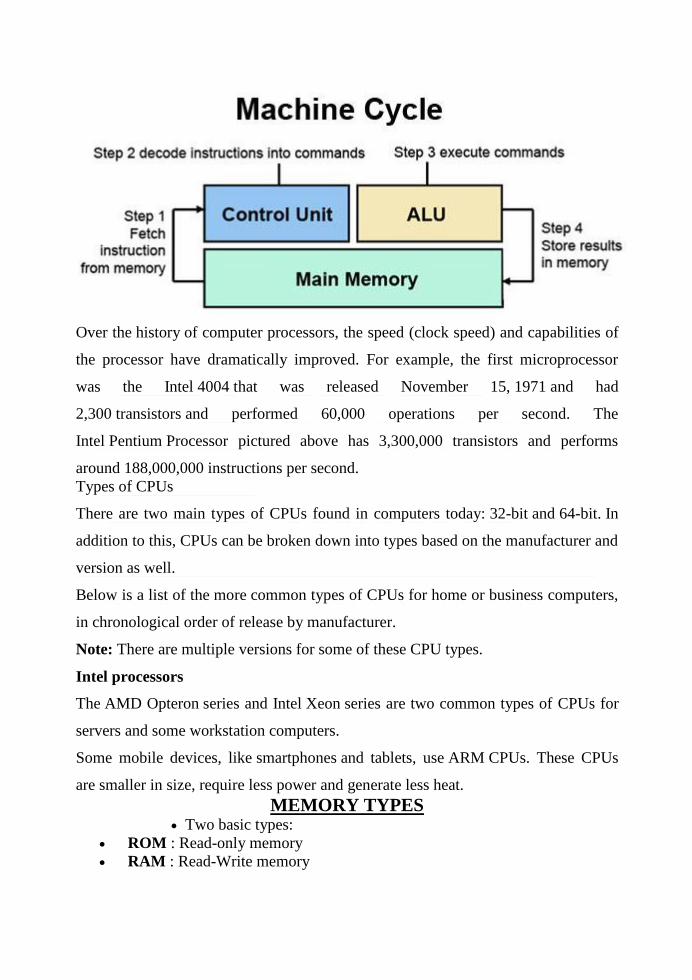
Over the history of computer processors, the speed (clock speed) and capabilities of
the processor have dramatically improved. For example, the first microprocessor
was the Intel 4004 that was released November 15, 1971 and had
2,300 transistors and performed 60,000 operations per second. The
Intel Pentium Processor pictured above has 3,300,000 transistors and performs
around 188,000,000 instructions per second.
Types of CPUs
There are two main types of CPUs found in computers today: 32-bit and 64-bit. In
addition to this, CPUs can be broken down into types based on the manufacturer and
version as well.
Below is a list of the more common types of CPUs for home or business computers,
in chronological order of release by manufacturer.
Note: There are multiple versions for some of these CPU types.
Intel processors
The AMD Opteron series and Intel Xeon series are two common types of CPUs for
servers and some workstation computers.
Some mobile devices, like smartphones and tablets, use ARM CPUs. These CPUs
are smaller in size, require less power and generate less heat.
MEMORY TYPES Two basic types:
ROM : Read-only memory
RAM : Read-Write memory

Four commonly used memories:
ROM
Flash (EEPROM)
Static RAM (SRAM)
Dynamic RAM (DRAM)
Generic pin configuration:
Memory Chips
The number of address pins is related to the number of memory locations .
Common sizes today are 1K to 256M locations.
Therefore, between 10 and 28 address pins are present.
The data pins are typically bi-directional in read-write memories.
The number of data pins is related to the size of the memory location .
For example, an 8-bit wide (byte-wide) memory device has 8 data pins.
Catalog listing of 1K X 8 indicate a byte addressable 8K memory.
Each memory device has at least one chip select ( CS ) or chip enable ( CE )
or select ( S ) pin that enables the memory device.
This enables read and/or write operations.
If more than one are present, then all must be 0 in order to perform a read or
write.
Memory Chips
Each memory device has at least one control pin.
For ROMs, an output enables (OE) or gate (G) is present.
The OE pin enables and disables a set of tristate buffers.
For RAMs, a read-write (R/W) or write enable (WE) and read enable (OE)
are present.
For dual control pin devices, it must be hold true that both are not 0 at the
same time.
ROM:
Non-volatile memory: Maintains its state when powered down.
There are several forms:

ROM: Factory programmed, cannot be changed. Older style.
PROM: Programmable Read-Only Memory.
Field programmable but only once.
Older style.
EPROM: Erasable Programmable Read-Only Memory.
Reprogramming requires up to 20
minutes of high-intensity UV light
exposure.
Memory Chips
ROMs (cont):
Flash EEPROM: Electrically Erasable Programmable ROM.
Also called EAROM (Electrically
Alterable ROM) and NOVRAM(NOn-
Volatile RAM).
Writing is much slower than a normal
RAM.
Used to store setup information, e.g.
video card, on computer systems.
Can be used to replace EPROM for
BIOS memory.
EPROMs
Intel 2716 EPROM (2K X 8):
EPROMs
2716 Timing diagram:

Sample of the data sheet for the 2716 A.C. Characteristics.
Symbol Parameter Limits
Unit Test Condition Min Typ. Max
tACC1 Addr. to Output Delay 250 450 ns PD/PGM= CS
=VIL
tOH Addr. to Output Hold 0 ns PD/PGM= CS
=VIL
tDF Chip Deselect to Output
Float 0 100 ns PD/PGM=VIL
... ... ... ... ... ... ...
This EPROM requires a wait state for use with the 8086
( 460ns constraint).
SRAMs
TI TMS 4016 SRAM (2K X 8):
Virtually identical to the EPROM with respect to the pinout.
However, access time is faster (250ns).

o See the timing diagrams and data sheets in text.
SRAMs used for caches have access times as low as 10ns .
DRAMs
DRAM:
SRAMs are limited in size (up to about 128K X 8).
DRAMs are available in much larger sizes, e.g., 64M X 1.
DRAMs MUST be refreshed (rewritten) every 2 to 4 ms
Since they store their value on an integrated capacitor that loses charge over
time.
This refresh is performed by a special circuit in the DRAM which refreshes
the entire memory using 256 reads.
Refresh also occurs on a normal read, write or during a special refresh cycle.
The large storage capacity of DRAMs make it impractical to add the required
number of address pins.
Instead, the address pins are multiplexed .
DRAMs
TI TMS4464 DRAM (64K X 4):
The TMS4464 can store a total of 256K bits of data.
It has 64K addressable locations which means it needs 16 address inputs, but
it has only 8 .
The row address (A 0 through A 7 ) are placed on the address pins and
strobed into a set of internal latches.
The column addres (A 8 through A 15 ) is then strobed in using CAS.
DRAMs
TI TMS4464 DRAM (64K X 4) Timing Diagram:

o CAS also performs the function of the chip select
input.
DRAMs
Larger DRAMs are available which are organized as 1M X 1 , 4M X 1 , 16M
X 1 , 64M X 1(with 256M X 1 available soon).
DRAMs are typically placed on SIMM (Single In-line Memory Modules)
boards.
30-pin SIMMs come in 1M X 8 , 1M X 9 (parity), 4M X 8 , 4M X 9 .
72-pin SIMMs come in 1 / 2 / 3 / 8 / 16M X 32 or 1M X 36 (parity).
DRAMs
Pentiums have a 64-bit wide data bus.
The 30-pin and 72-pin SIMMs are not used on these systems.
Rather, 64-bit DIMMs (Dual In-line Memory Modules) are the standard.
These organize the memory 64-bits wide.
The board has DRAMs mounted on both sides and is 168 pins.
Sizes include 2M X 64 (16M), 4M X 64 (32M), 8M X 64 (64M) and 16M X
64 (128M).
The DIMM module is available
in DRAM, EDO and SDRAM (and NVRAM) with and without an
EPROM.
The EPROM provides information abou the size and speed of the memory device
for PNP applications.
INPUT DEVICES
An input device for a computer allows you to enter information. The most
fundamental pieces of information are keystrokes on a keyboard and clicks with a
mouse. These two input devices are essential for you to interact with your computer.
Many other input devices exist for entering other types of information, such as
images, audio and video. Input devices represent one type of computer peripheral -
the other two types are output devices and storage devices.
Examples of Input Devices
A keyboard is the most fundamental input device for any computer system. In the
early days of computing, it was typically the only input device. A keyboard contains
keys for letters and numbers as well as for specialized tasks, such as Enter, Delete,
etc.

Typical keyboard for a desktop computer
When operating systems started to use graphical user interface (GUI), the mouse
was developed as a pointing device. Typically, a mouse resides on a flat surface, and
by moving the mouse, you can move the pointer on the screen. One or more buttons
on the mouse allow you to enter instructions by clicking. Most models also include a
wheel for scrolling.
Typical mouse for a desktop computer
Desktop computers have a separate keyboard and mouse, but for laptops, these are
integrated into a computer system itself. In laptops, the mouse is actually substituted
with a touchpad or trackpad. This is a specialized surface that follows the motion of
your finger. You can still connect an external mouse to a laptop if you prefer.

Keyboard and trackpad on a laptop computer
Another common input device is an image scanner. A typical desktop or flatbed
scanner is a device that optically scans printed images and paper documents and
converts them into digital images. In most scanners, you place the document on a
glass plate and place an opaque cover over it. A bright light moves across the image,
and the reflection is captured by a sensor, which converts the document to a digital
image.
Flatbed scanner
Audio and video can be recorded using a microphone and video camera,
respectively. Due to the popularity of video conferencing using services like Skype,
these are now typically integrated in most laptops and monitor displays for desktops;
however, you can also connect an external webcam, which can record both audio
and video.

External webcam for video conferencing
DISPLAY DEVICES
A display device is an output device for presentation of information in visual or
tactile form (the latter used for example in tactile electronic displays for blind
people). When the input information is supplied as an electrical signal, the display is
called an electronicdisplay.

Cathode Ray Tube (CRT)
Electron gun = cathode + control grid
Pixel ratio = height of pixel width of pixel
Aspect ratio = # rows in display __# columns in display
Resolution -- Number of pixels per linear distance (e.g., 640 × 400-pixel
display).
COLOR -- 3 different phosphors + 3 different gusns (e.g., red, green, and blue)
Phosphore
The electron beam causes the phosphor’s atoms to move into
higher energy state
The atoms give off energy as light when they return to their stable state
REFRESHMENT

Persistence -- Time for emitted light to fade by 90% of its intensity
(normally 10 to 60 microseconds).
Refresh -- Redrawing of an image to preserve it on a screen
Refresh rate -- Number of times per second the image is redrawn
(normally > 60 Hz)
Flicker -- Develops in low refresh rate because the eyes can not integrate the
individual light impulses comming from a pixel.
Critical fushion frequency -- Refresh rate above which a picture stops
flickering and fuses into a steady image. Depends on
o Phosphor’s persistence
o Image intensity
o Ambient room lighting
o Wavelenght of emitted light
o The observer
Raster Display
SYSTEM COMPONENTS
The screen is subdivided into a matrix of pixels (smallest addressable units).
Raster scanline -- A line of pixels along the screen
Frame (refresh) buffer -- Block of memory used to store the screen pattern
HOW IT WORKS
The DISPLAY PROCESSOR produces the raster image in the frame buffer
from the commands
The VIDEO CONTROLLER moves the beam row wise across the pixels
setting it on and off according to the content of theframe buffer

The display must be refreshed to avoid flickering (raster image redisplayed
30 to 60 times pers second)
2-BIT BLACK-AND-WHITE GRAY LEVEL

00 0 3 of full intensity
01 1 3 of full intensity
10 2 3 of full intensity
11 3 3 of full intensity
FRAME BUFFER
Single-bit black-and-white frame buffer (monochrome, bitmap)
N-bit black-and-white gray level frame buffer (pixmap)
N-bit black-and-white gray level frame buffer with M-bit lookup table
N-bit color frame buffer with M-bit look-up table (typically N = 8 and M =
24)

"
/> " />
WHY USE A LOOK-UP TABLE?
Reduced memory for full array of colors
24 bit color * 1280 by 1024 resolution/ 8 bits per byte 4MB
Color table animation
2-BIT BLACK-AND-WHITE GRAY LEVEL FRAME BUFFER WITH 8-
BIT LUT
2-bit color level frame buffer with 24-bit LUT (e.g., RGB: red, green, blue)
Vector (or Random Scan) Display
Images are described in terms of line segments rather than pixels.
Display processor cycles through the commands

Advatages / Disadvantages
HARD COPY DEVICES
Hard copy devices are used for draw a graphical image or another information on to
the paper. Mainly two types of hard copy devices namely printer and plotter that can
be used for print image,line or charater on to the paper.
Hard-Copy Devices
We can obtain hard-copy output for our images in several formats. For
presentations or archiving, we can send image files to devices or service bureaus that
will produce 35-mm slides or overhead transparencies. To put images on film, we
can simply photograph a scene displayed on a video monitor. And we can put our
pictures on paper by directing graphics output to a printer or plotter.
The quality of the pictures obtained from a device depends on dot size and the
number of dots per inch, or lines per inch, that can be displayed. To produce smooth
characters in printed text strings, higher-quality printers shift dot positions so that
adjacent dots overlap.
Printers produce output by either impact or nonimpact methods. Impact printers
press formed character faces against an inked ribbon onto the paper. A line printer is
an example of an impact device, with the typefaces mounted on bands, chains,
drums, or wheels. Nonimpact printers and plotters use laser techniques, ink-jet
sprays, xerographic processes (as used in photocopying machines), electrostatic
methods, and electrothermal methods to get images onto paper.
Character impact printers often have a dot-matrix print head containing a
rectangular array of protruding wire pins, with the number of pins depending on the
quality of the printer. Individual characters or graphics patterns are obtained by
retracting certain pins so that the remaining pins form the pattern to be printed.
Figure 2-58 shows a picture printed on a dot-matrix printer.

Figure :1 A picture generated on a dot-
matrix printer showing how the
density of the dot patterns can
be varied to produce light and
dark areas. (Courtesy of Apple
Computer, Inc.)
In a laser device, a laser beam mates a charge distribution on a rotating drum coated with a
photoelectric material, such as selenium. Toner is applied to the drum and then transferred to
paper. Figure 2-59 shows examples of desktop laser printers with a resolution of 360 dots per
inch.
Figure :2 Small-footprint laser printers. (Courtesy of Texas Instruments.)
Figure :3 A 360-dot-per-inch desktop ink-jet plotter. (Courtesy of Summagraphics Corporation.)
Ink-jet methods produce output by squirting* ink in horizontal rows across a roll of paper
wrapped on a drum. The electrically charged ink stream is deflected by an electric field to
produce dot-matrix patterns. A desktop ink-jet plotter with a resolution of 360 dots per inch is
shown in Fig. 3, and examples of larger high-resolution ink-jet printer/plotters are shown in
Fig.4

Figure :4 Floor-model, ink-jet color printers that use variable dot size to achieve an
equivalent resolution of 1500 to 1800 dots per inch.
An electrostatic device places a negative charge on the paper, one complete row at a time
along the length of the paper. Then the paper is exposed to a toner. The toner is positively
charged and so is attracted to the negatively charged areas, where it adheres to produce the
specified output. A color electrostatic printer/plotter is shown in Fig. 2-62. Electrothermal
methods use heat in a dot-matrix print head to output patterns on heat-sensitive paper.
Figure :5 An electrostatic printer that can display 400
dots per inch.
We can get limited color output on an impact printer by using different-colored ribbons.
Nonimpact devices use various techniques to combine three color pigments (cyan, magenta, and
yellow) to produce a range of color patterns. Laser and xerographic* devices deposit the three
pigments* on separate passes; ink-jet methods shoot the three colors simultaneously on a single
pass along each print tine on the paper.

STORAGE DEVICES
What are Storage devices?
Storage Devices are the data storage devices that are used in the computers to store
the data. The computer has many types of data storage devices. Some of them can be
classified as the removable data Storage Devices and the others as the non removable
data Storage Devices.
The memory is of two types; one is the primary memory and the other one is
the secondary memory.
The primary memory is the volatile memory and the secondary memory is the non
volatile memory. The volatile memory is the kind of the memory that is erasable and
the non volatile memory is the one where in the contents cannot be erased. Basically
when we talk about the data storage devices it is generally assumed to be the
secondary memory.
The secondary memory is used to store the data permanently in the computer.
The secondary storage devices are usually as follows: hard disk drives – this is the
most common type of storage device that is used in almost all the computer systems.
The other ones include the floppy disk drives, the CD ROM, and the DVD ROM.
The flash memory, the USB data card etc.
Find out more ... Navigate through the list of storage devices given on the right side.
Floppy discs:
A floppy disk is a data storage medium that is composed of a disk of thin, flexible
floppy)magnetic storagemedium encased in asquareor rectangularplasticshell. Floppy
disks are read and written by afloppy disk drive.
Application
Any use where small files such as word processing, small spreadsheets and databases
need to be moved from one computer to another.
Useful to backup small data files.

Fixed hard discs
A hard disk drive is the device used to store large amounts of digital information in
computers and related equipment like iPods and games consoles such as the Xbox
360 and PS3.
Hard disk drives are used to store operating systems, software and working data.
These are suitable for any application which requires very fast access to data for
both reading and writing to. However, Hard disk drives may not be suitable for
applications which need portability.
Almost all computers used a fixed hard disc. Used for on-line and real time processes
requiring direct access. Used in file servers for computer networks to store large
amount of data.
Portable hard discs
Portable hard discs are good fun because you can carry data about all over the place
and transfer information, programs, pictures, etc between computers.
Advantages:
Greatly improved data cargo carrying capacity (relative to the 1.44 Mb floppy disc).
You don't need to worry about the other person having the same type of special
cartridge drive as yourself.
Disadvantages:
Hard drives have to be handled quite carefully, and when being transported should be
wrapped in something soft and put in a padded bag.
More expensive than other forms of removable media.
Application
Portable disc discs are used to store very large files which need transporting from
one computer to another and price is not an issue.
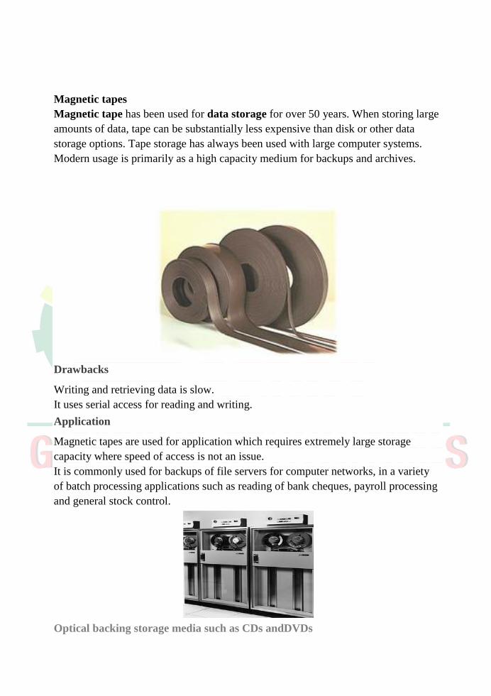
Magnetic tapes
Magnetic tape has been used for data storage for over 50 years. When storing large
amounts of data, tape can be substantially less expensive than disk or other data
storage options. Tape storage has always been used with large computer systems.
Modern usage is primarily as a high capacity medium for backups and archives.
Drawbacks
Writing and retrieving data is slow.
It uses serial access for reading and writing.
Application
Magnetic tapes are used for application which requires extremely large storage
capacity where speed of access is not an issue.
It is commonly used for backups of file servers for computer networks, in a variety
of batch processing applications such as reading of bank cheques, payroll processing
and general stock control.
Optical backing storage media such as CDs andDVDs
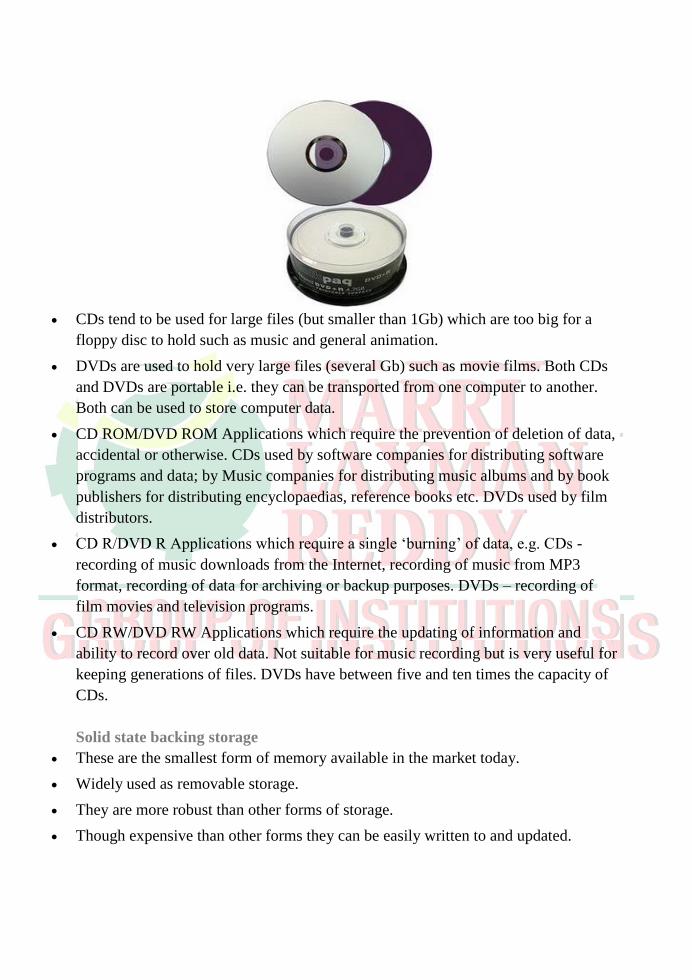
CDs tend to be used for large files (but smaller than 1Gb) which are too big for a
floppy disc to hold such as music and general animation.
DVDs are used to hold very large files (several Gb) such as movie films. Both CDs
and DVDs are portable i.e. they can be transported from one computer to another.
Both can be used to store computer data.
CD ROM/DVD ROM Applications which require the prevention of deletion of data,
accidental or otherwise. CDs used by software companies for distributing software
programs and data; by Music companies for distributing music albums and by book
publishers for distributing encyclopaedias, reference books etc. DVDs used by film
distributors.
CD R/DVD R Applications which require a single ‘burning’ of data, e.g. CDs -
recording of music downloads from the Internet, recording of music from MP3
format, recording of data for archiving or backup purposes. DVDs – recording of
film movies and television programs.
CD RW/DVD RW Applications which require the updating of information and
ability to record over old data. Not suitable for music recording but is very useful for
keeping generations of files. DVDs have between five and ten times the capacity of
CDs.
Solid state backing storage
These are the smallest form of memory available in the market today.
Widely used as removable storage.
They are more robust than other forms of storage.
Though expensive than other forms they can be easily written to and updated.

Memory sticks/Pen drives
USB flash drives are typically removable and rewritable, much smaller than a floppy
disk. Storage capacities typically range from 64 MB to 64 GB. USB flash drives
offer potential advantages over other portable storage devices, particularly the floppy
disk.
They have a more compact shape, operate faster, hold much more data, have a more
durable design, and operate more reliably due to their lack of moving parts. Flash
drives are widely used to transport files and backup data from computer to computer.
Flash memory cards
A memory card or flash memory card is a solid-state electronic flash memory data
storage device used with digital cameras, handheld and Mobile computers,
telephones, music players, video game consoles, and other electronics.
Nowadays, most new PCs have built-in slots for a variety of memory cards; Memory
Stick, CompactFlash, SD, etc. Some digital gadgets support more than one memory
card to ensure compatibility.