Embed Size (px)
Citation preview

DRAWN SP 12/09/16
© APPLIDYNE AUSTRALIA PTY LTD, ADELAIDE
PROJECT IDENTIFICATION
CHECKED PvdL 16/9/16
CUSTOMER
CAD AND DRAWING BEST PRACTICES GUIDE
FUNCTION NO.
B Updated paras 3.1.1, 3.1.2 to clarify and 3.4.2 to fix dimension error PvdL 28/09/16 CUSTOMER DRG REF
A ORIGINAL LEVEL A3 REV MOD NO DESCRIPTION OF CHANGE APPD DATE CLASSIFICATION 1
CAD and Drawing Best Practices Guide At Applidyne we pride ourselves on our high level of quality and consistency in all work we undertake, which frequently includes CAD and drawings. A product that has been designed by Applidyne can be in service for years after which a client returns requesting design changes, improvements or otherwise querying design decisions. For CAD engineers unfamiliar with the project, maintaining a consistent CAD standard reduces down time understanding design intent, and speeds up any modifications required to CAD. This DDS presents the Applidyne CAD and Drawing Best Practices that should be adhered to by mechanical engineers to ensure this consistency and quality. All detail and critical designs should comply with these practices. Preliminary designs can fluctuate rapidly in design intent, so strict adherence in these instances is not necessary (but still recommended).
1 Part modelling
1.1 Have a modelling plan
Time can be wasted if no time is invested in planning a model. Eg for a drip tray with 3D surfaces, consider solid modelling and then shelling vs surface modelling and then thickening. If no plan is made, it is because you aren’t familiar enough with CAD and need more training. A plan should take (be it sketch or in your head) <3 mins.
1.2 Set material properties so mass is calculated correctly
Edit>Setup>Material>
1.3 Always model at full scale
This allows other users to continue / modify your CAD in future, even in cases you’re sure no-one would ever use it. This also assists in identifying any potential design issues or working through a change in design intent.
1.4 Use symmetry where possible
Using symmetry simplifies sketches and will generally make further modelling and assembly easier down the track.
1.5 No unconstrained features
Unconstrained features can lead to issues when trying to modify the part down the track.
ProE shows an unconstrained dimension as a “weak” dimension

DRAWN SP 12/09/16
© APPLIDYNE AUSTRALIA PTY LTD, ADELAIDE
PROJECT IDENTIFICATION
CHECKED PvdL 16/9/16
CUSTOMER
CAD AND DRAWING BEST PRACTICES GUIDE
FUNCTION NO.
B Updated paras 3.1.1, 3.1.2 to clarify and 3.4.2 to fix dimension error PvdL 28/09/16 CUSTOMER DRG REF
A ORIGINAL LEVEL A3 REV MOD NO DESCRIPTION OF CHANGE APPD DATE CLASSIFICATION 2
1.6 Imagine how you would measure each dimension
When dimensioning new features, imagine how you would measure each dimension before you place them, dimensioning to a rad or fillet for example would be very tricky to measure and is generally bad CAD practice.
1.7 Avoid referencing features that are likely to change
If a feature is likely to change down the track then be careful referencing it, e.g. the slot in the right hand image below will change if you move the holes.
1.8 Imagine how you would make each part
For example, if you are designing a part that will be turned on a lathe use revolves rather than extrudes. This will simplify the transition from part to drawing down the track.
1.9 Don’t fill in a feature when you could delete it
Keep your model tree tidy, if you need to remove a feature then delete it, don’t just fill it in
BAD GOOD
e.g. Using the extrude tool to fill a hole is bad practice
GOOD BAD

DRAWN SP 12/09/16
© APPLIDYNE AUSTRALIA PTY LTD, ADELAIDE
PROJECT IDENTIFICATION
CHECKED PvdL 16/9/16
CUSTOMER
CAD AND DRAWING BEST PRACTICES GUIDE
FUNCTION NO.
B Updated paras 3.1.1, 3.1.2 to clarify and 3.4.2 to fix dimension error PvdL 28/09/16 CUSTOMER DRG REF
A ORIGINAL LEVEL A3 REV MOD NO DESCRIPTION OF CHANGE APPD DATE CLASSIFICATION 3
1.10 Model “master” dimensions parametrically, using planes and datums
This makes it much easier to tweak key dimensions further down the track with less risk of the history tree falling over and other features losing references.
Use relations to control common dimensions
Set datum offsets using the relation
Use the ‘extrude to selection’ tool to set the length of the extrude. Select the desired datum plane as the reference.
Adjusting the dimension relations in the relations manager will update the datum planes and therefore the extrude distances without affecting other dimensions.

DRAWN SP 12/09/16
© APPLIDYNE AUSTRALIA PTY LTD, ADELAIDE
PROJECT IDENTIFICATION
CHECKED PvdL 16/9/16
CUSTOMER
CAD AND DRAWING BEST PRACTICES GUIDE
FUNCTION NO.
B Updated paras 3.1.1, 3.1.2 to clarify and 3.4.2 to fix dimension error PvdL 28/09/16 CUSTOMER DRG REF
A ORIGINAL LEVEL A3 REV MOD NO DESCRIPTION OF CHANGE APPD DATE CLASSIFICATION 4
1.11 Dimension diameters on revolve features
In nearly all cases diameters are dimensions of interest, not radii. Shafts, screws, o-ring grooves, circlips, etc are all sized based on diameters. Ensure revolve sketches follow suit too!
1.12 If a part is hard to model it is likely to be hard to manufacture
Do not insert overly complex features like 3D surfaces, holes on angled faces, undercuts in holes, etc unless they are absolutely necessary. As a general rule of thumb, the more features in a parts feature tree, the harder it will be to manufacture and thus the higher the cost. The best designs are often the simplest!
1.13 Sketching should encompass primary features only
Secondary features such as chamfers, straight holes, rounds and fillets should not be created within the sketch but should be defined and added using feature operations. This reduces confusion for other users and keeps sketches neat.
1.14 Avoid circular references
Circular references can occur particularly when creating parts within assemblies with references to other parts. This is a great time saver when you need a part to change length as another part changes, however issues can occur when parts are linked together in a “circular reference”.
2 Assembly modelling
2.1.1 Plan out the master assembly
Break down the master assembly into groups of sub-assemblies, each requiring their own assembly file. This makes generating drawings easier, as assemblies don’t need to be remade for the sake of the BOM (Bill of Materials). Remember fabrication of two parts, installation of nutserts and installation of stud welds count as assemblies!
2.1.2 Group together fasteners
In the part tree, always group fastener types together (eg “SHCS_M8x20_SS”), and then all fastener types together.
Fastener “type” group
Main fastener group
DRAWN SP 12/09/16
© APPLIDYNE AUSTRALIA PTY LTD, ADELAIDE
PROJECT IDENTIFICATION
CHECKED PvdL 16/9/16
CUSTOMER
CAD AND DRAWING BEST PRACTICES GUIDE
FUNCTION NO.
B Updated paras 3.1.1, 3.1.2 to clarify and 3.4.2 to fix dimension error PvdL 28/09/16 CUSTOMER DRG REF
A ORIGINAL LEVEL A3 REV MOD NO DESCRIPTION OF CHANGE APPD DATE CLASSIFICATION 5
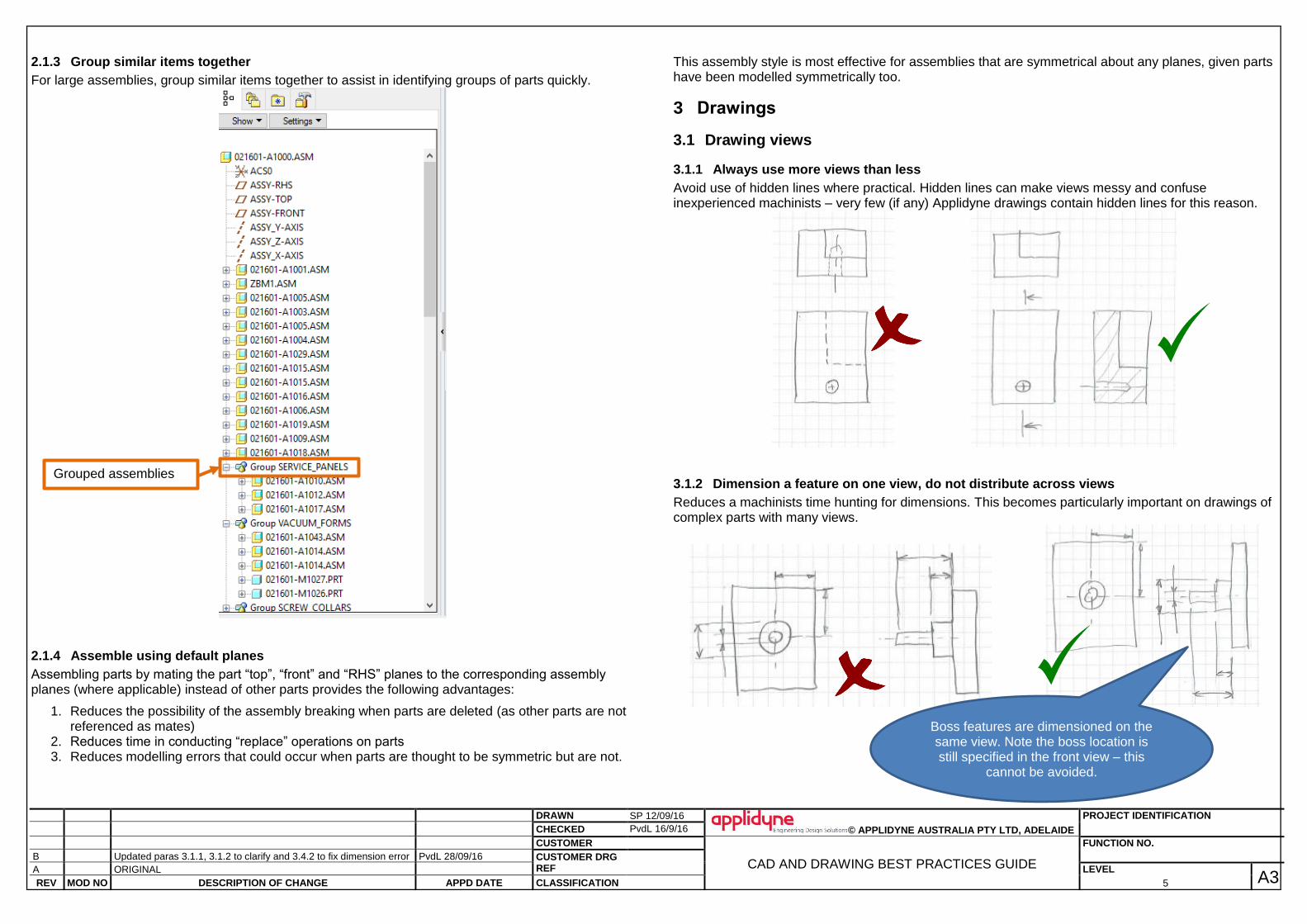
2.1.3 Group similar items together
For large assemblies, group similar items together to assist in identifying groups of parts quickly.
2.1.4 Assemble using default planes
Assembling parts by mating the part “top”, “front” and “RHS” planes to the corresponding assembly planes (where applicable) instead of other parts provides the following advantages:
1. Reduces the possibility of the assembly breaking when parts are deleted (as other parts are not referenced as mates)
2. Reduces time in conducting “replace” operations on parts 3. Reduces modelling errors that could occur when parts are thought to be symmetric but are not.
This assembly style is most effective for assemblies that are symmetrical about any planes, given parts have been modelled symmetrically too.
3 Drawings
3.1 Drawing views
3.1.1 Always use more views than less
Avoid use of hidden lines where practical. Hidden lines can make views messy and confuse inexperienced machinists – very few (if any) Applidyne drawings contain hidden lines for this reason.
3.1.2 Dimension a feature on one view, do not distribute across views
Reduces a machinists time hunting for dimensions. This becomes particularly important on drawings of complex parts with many views.
Grouped assemblies
Boss features are dimensioned on the same view. Note the boss location is still specified in the front view – this
cannot be avoided.
DRAWN SP 12/09/16
© APPLIDYNE AUSTRALIA PTY LTD, ADELAIDE
PROJECT IDENTIFICATION
CHECKED PvdL 16/9/16
CUSTOMER
CAD AND DRAWING BEST PRACTICES GUIDE
FUNCTION NO.
B Updated paras 3.1.1, 3.1.2 to clarify and 3.4.2 to fix dimension error PvdL 28/09/16 CUSTOMER DRG REF
A ORIGINAL LEVEL A3 REV MOD NO DESCRIPTION OF CHANGE APPD DATE CLASSIFICATION 6
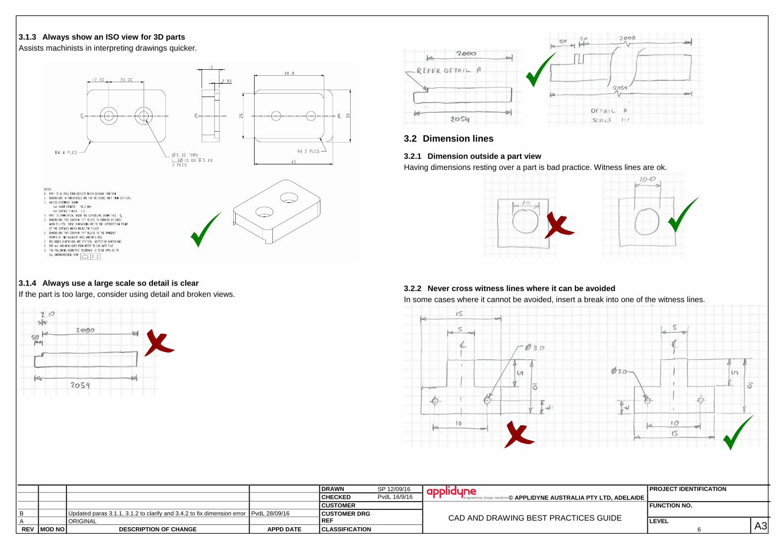
3.1.3 Always show an ISO view for 3D parts
Assists machinists in interpreting drawings quicker.
3.1.4 Always use a large scale so detail is clear
If the part is too large, consider using detail and broken views.
3.2 Dimension lines
3.2.1 Dimension outside a part view
Having dimensions resting over a part is bad practice. Witness lines are ok.
3.2.2 Never cross witness lines where it can be avoided
In some cases where it cannot be avoided, insert a break into one of the witness lines.

DRAWN SP 12/09/16
© APPLIDYNE AUSTRALIA PTY LTD, ADELAIDE
PROJECT IDENTIFICATION
CHECKED PvdL 16/9/16
CUSTOMER
CAD AND DRAWING BEST PRACTICES GUIDE
FUNCTION NO.
B Updated paras 3.1.1, 3.1.2 to clarify and 3.4.2 to fix dimension error PvdL 28/09/16 CUSTOMER DRG REF
A ORIGINAL LEVEL A3 REV MOD NO DESCRIPTION OF CHANGE APPD DATE CLASSIFICATION 7
3.3 How to dimension
3.3.1 Use common datum where appropriate
Avoids tolerance stack ups.
3.3.2 Functional dimensions should be dimensioned directly
Reduces tolerance stack up.
3.3.3 Avoid dimensioning critical surfaces from imaginary datums.
This makes it easier to inspect parts and return to the manufacturer in the event of a non-conformance to drawing. It also makes it easier for the manufacturer to check themselves before release.
3.4 Reference dimensions
3.4.1 Always provide external dimensions
Makes it easy for the machinist to order material. ( ) and REF denote reference dimensions.

DRAWN SP 12/09/16
© APPLIDYNE AUSTRALIA PTY LTD, ADELAIDE
PROJECT IDENTIFICATION
CHECKED PvdL 16/9/16
CUSTOMER
CAD AND DRAWING BEST PRACTICES GUIDE
FUNCTION NO.
B Updated paras 3.1.1, 3.1.2 to clarify and 3.4.2 to fix dimension error PvdL 28/09/16 CUSTOMER DRG REF
A ORIGINAL LEVEL A3 REV MOD NO DESCRIPTION OF CHANGE APPD DATE CLASSIFICATION 8
3.4.2 Provide other useful info for machinist
Save machinists from having to make calculations for any dimensions you think they’ll need.
3.5 Geometric tolerancing
3.5.1 Use it!
In most cases dimensioning size is insufficient, geometry must be defined too. Geometric tolerancing exists for flatness, profile, position, perpendicularity, parallelism and more! The following example provides a positional tolerance between the surfaces shown:
3.5.2 Dimensioning holes
Always use geometric tolerancing when tolerancing holes. This reduces the maximum deviation of hole position.
This tolerancing scheme (like all good tolerancing) will save money – here it reduces the precision that the machinist must work to (from 0.1mm to 0.14mm) yet achieves the same result.
Saves machinist
from calculating
angle.

DRAWN SP 12/09/16
© APPLIDYNE AUSTRALIA PTY LTD, ADELAIDE
PROJECT IDENTIFICATION
CHECKED PvdL 16/9/16
CUSTOMER
CAD AND DRAWING BEST PRACTICES GUIDE
FUNCTION NO.
B Updated paras 3.1.1, 3.1.2 to clarify and 3.4.2 to fix dimension error PvdL 28/09/16 CUSTOMER DRG REF
A ORIGINAL LEVEL A3 REV MOD NO DESCRIPTION OF CHANGE APPD DATE CLASSIFICATION 9
4 Other tips
4.1 Change ProE background to white for screen shots
Changing the ProE background colour to white is professional for any DDS or reporting purposes. It also saves ink when printing images! View>Display Settings>System Colours>Black on white or Default
Sets background white
Returns background to ProE colours.