Embed Size (px)
Citation preview

Application Technique
Cable Pull Switch Connected in Series via a Compact GuardLogix Controller Safety FunctionProducts: Compact GuardLogix® Controller, Lifeline™ 4 Cable Pull Switch, E-stop Button, POINT Guard I/O™ Safety Modules
Safety Rating: CAT. 3, PLd to ISO 13849-1: 2008
Topic Page
Important User Information 2
General Safety Information 3
Introduction 3
Safety Function Realization: Risk Assessment 4
Cable Pull Switch Safety Function 4
Safety Function Requirements 4
Functional Safety Description 5
Bill of Material 5
Setup and Wiring 5
Safety Distance Considerations 6
Calculation of the Performance Level 17
Verification and Validation Plan 18
Additional Resources 21

Cable Pull Switch Connected in Series via a Compact GuardLogix Controller Safety Function
Important User Information
Read this document and the documents listed in the additional resources section about installation, configuration, and operation of this equipment before you install, configure, operate, or maintain this product. Users are required to familiarize themselves with installation and wiring instructions in addition to requirements of all applicable codes, laws, and standards.
Activities including installation, adjustments, putting into service, use, assembly, disassembly, and maintenance are required to be carried out by suitably trained personnel in accordance with applicable code of practice.
If this equipment is used in a manner not specified by the manufacturer, the protection provided by the equipment may be impaired.
In no event will Rockwell Automation, Inc. be responsible or liable for indirect or consequential damages resulting from the use or application of this equipment.
The examples and diagrams in this manual are included solely for illustrative purposes. Because of the many variables and requirements associated with any particular installation, Rockwell Automation, Inc. cannot assume responsibility or liability for actual use based on the examples and diagrams.
No patent liability is assumed by Rockwell Automation, Inc. with respect to use of information, circuits, equipment, or software described in this manual.
Reproduction of the contents of this manual, in whole or in part, without written permission of Rockwell Automation, Inc., is prohibited.
Throughout this manual, when necessary, we use notes to make you aware of safety considerations.
Labels may also be on or inside the equipment to provide specific precautions.
WARNING: Identifies information about practices or circumstances that can cause an explosion in a hazardous environment, which may lead to personal
injury or death, property damage, or economic loss.
ATTENTION: Identifies information about practices or circumstances that can lead to personal injury or death, property damage, or economic loss.
Attentions help you identify a hazard, avoid a hazard, and recognize the consequence.
IMPORTANT Identifies information that is critical for successful application and understanding of the product.
SHOCK HAZARD: Labels may be on or inside the equipment, for example, a drive or motor, to alert people that dangerous voltage may be present.
BURN HAZARD: Labels may be on or inside the equipment, for example, a drive or motor, to alert people that surfaces may reach dangerous temperatures.
ARC FLASH HAZARD: Labels may be on or inside the equipment, for example, a motor control center, to alert people to potential Arc Flash. Arc Flash will
cause severe injury or death. Wear proper Personal Protective Equipment (PPE). Follow ALL Regulatory requirements for safe work practices and for
Personal Protective Equipment (PPE).
2 Rockwell Automation Publication SAFETY-AT092B-EN-P - July 2016

Cable Pull Switch Connected in Series via a Compact GuardLogix Controller Safety Function
General Safety Information
Contact Rockwell Automation to learn more about our safety risk assessment services.
Safety Distance Calculations
Non-separating safeguards provide no physical barrier to prevent access to a hazard. Publications that offer guidance for calculating compliant safety distances for safety systems that use non-separating safeguards, such as light curtains, scanners, two-hand controls, or safety mats, include the following:
EN ISO 13855:2010 (Safety of Machinery – Positioning of safeguards with respect to the approach speeds of parts of the human body)
EN ISO 13857:2008 (Safety of Machinery – Safety distances to prevent hazardous zones being reached by upper and lower limbs
ANSI B11:19 2010 (Machines – Performance Criteria for Safeguarding)
Separating safeguards monitor a moveable, physical barrier that guards access to a hazard. Publications that offer guidance for calculating compliant access times for safety systems that use separating safeguards, such as gates with limit switches or interlocks (including SensaGuard™ switches), include the following:
EN ISO 13850:2015 (Safety of Machinery – Emergency-stop functions – Principles for design)
EN ISO 13855:2010 (Safety of Machinery – Positioning of safeguards with respect to the approach speeds of parts of the human body)
EN ISO 13857:2008 (Safety of Machinery – Safety distances to prevent hazardous zones being reached by upper and lower limbs
ANSI B11:19 2010 (Machines – Performance Criteria for Safeguarding)
In addition, consult relevant national or local safety standards to assure compliance.
Introduction
This safety function application technique explains how to wire, configure, and program a Compact GuardLogix® controller and POINT Guard I/O™ module to monitor a series of dual-channel cable pull switches. If any of the cable pull switches are actuated, or if a fault is detected in the monitoring circuit, the GuardLogix® controller de-energizes the final control device, in this case, a redundant pair of 100S contactors.
IMPORTANT This application example is for advanced users and assumes that you are trained and experienced in safety system requirements.
ATTENTION: Perform a risk assessment to make sure that all task and hazard combinations have been identified and addressed. The risk assessment can require
additional circuitry to reduce the risk to a tolerable level. Safety circuits must consider safety distance calculations, which are not part of the scope of this
document.
ATTENTION: While safety distance or access time calculations are beyond the scope of this document, compliant safety circuits must often consider a safety
distance or access time calculation.
Rockwell Automation Publication SAFETY-AT092B-EN-P - July 2016 3
Cable Pull Switch Connected in Series via a Compact GuardLogix Controller Safety Function
This example uses a Compact GuardLogix controller, but is applicable to any GuardLogix controller. The SISTEMA calculations that are shown later in this document would have to be recalculated using the actual products.
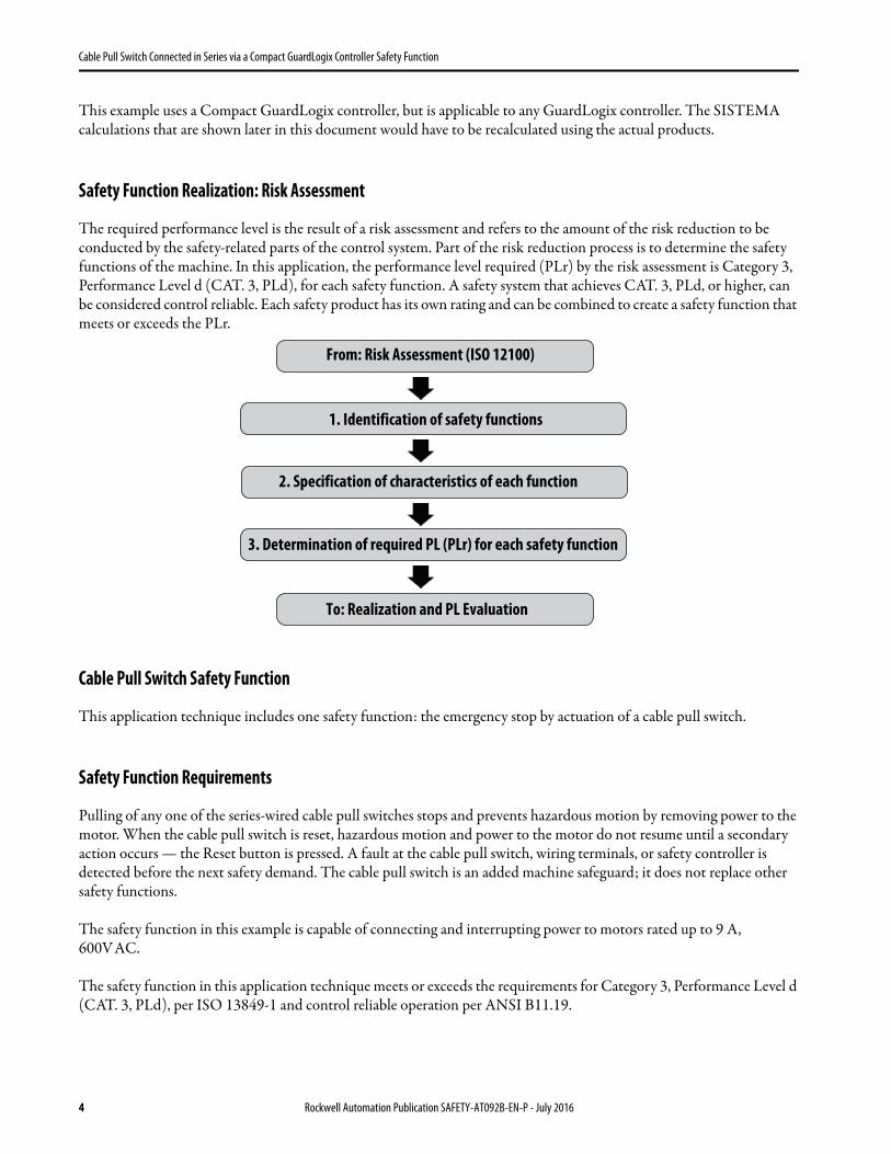
Safety Function Realization: Risk Assessment
The required performance level is the result of a risk assessment and refers to the amount of the risk reduction to be conducted by the safety-related parts of the control system. Part of the risk reduction process is to determine the safety functions of the machine. In this application, the performance level required (PLr) by the risk assessment is Category 3, Performance Level d (CAT. 3, PLd), for each safety function. A safety system that achieves CAT. 3, PLd, or higher, can be considered control reliable. Each safety product has its own rating and can be combined to create a safety function that meets or exceeds the PLr.
Cable Pull Switch Safety Function
This application technique includes one safety function: the emergency stop by actuation of a cable pull switch.
Safety Function Requirements
Pulling of any one of the series-wired cable pull switches stops and prevents hazardous motion by removing power to the motor. When the cable pull switch is reset, hazardous motion and power to the motor do not resume until a secondary action occurs — the Reset button is pressed. A fault at the cable pull switch, wiring terminals, or safety controller is detected before the next safety demand. The cable pull switch is an added machine safeguard; it does not replace other safety functions.
The safety function in this example is capable of connecting and interrupting power to motors rated up to 9 A, 600V AC.
The safety function in this application technique meets or exceeds the requirements for Category 3, Performance Level d (CAT. 3, PLd), per ISO 13849-1 and control reliable operation per ANSI B11.19.
From: Risk Assessment (ISO 12100)
1. Identification of safety functions
2. Specification of characteristics of each function
3. Determination of required PL (PLr) for each safety function
To: Realization and PL Evaluation
4 Rockwell Automation Publication SAFETY-AT092B-EN-P - July 2016
Cable Pull Switch Connected in Series via a Compact GuardLogix Controller Safety Function
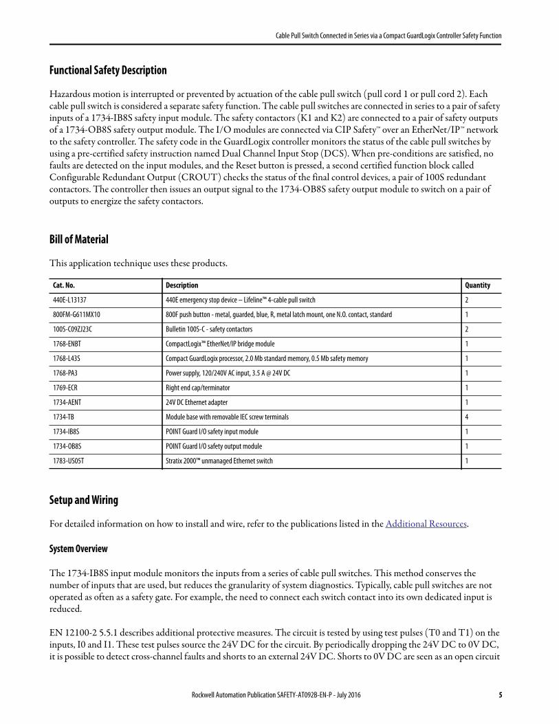
Functional Safety Description
Hazardous motion is interrupted or prevented by actuation of the cable pull switch (pull cord 1 or pull cord 2). Each cable pull switch is considered a separate safety function. The cable pull switches are connected in series to a pair of safety inputs of a 1734-IB8S safety input module. The safety contactors (K1 and K2) are connected to a pair of safety outputs of a 1734-OB8S safety output module. The I/O modules are connected via CIP Safety™ over an EtherNet/IP™ network to the safety controller. The safety code in the GuardLogix controller monitors the status of the cable pull switches by using a pre-certified safety instruction named Dual Channel Input Stop (DCS). When pre-conditions are satisfied, no faults are detected on the input modules, and the Reset button is pressed, a second certified function block called Configurable Redundant Output (CROUT) checks the status of the final control devices, a pair of 100S redundant contactors. The controller then issues an output signal to the 1734-OB8S safety output module to switch on a pair of outputs to energize the safety contactors.
Bill of Material
This application technique uses these products.
Setup and Wiring
For detailed information on how to install and wire, refer to the publications listed in the Additional Resources.
System Overview
The 1734-IB8S input module monitors the inputs from a series of cable pull switches. This method conserves the number of inputs that are used, but reduces the granularity of system diagnostics. Typically, cable pull switches are not operated as often as a safety gate. For example, the need to connect each switch contact into its own dedicated input is reduced.
EN 12100-2 5.5.1 describes additional protective measures. The circuit is tested by using test pulses (T0 and T1) on the inputs, I0 and I1. These test pulses source the 24V DC for the circuit. By periodically dropping the 24V DC to 0V DC, it is possible to detect cross-channel faults and shorts to an external 24V DC. Shorts to 0V DC are seen as an open circuit
Cat. No. Description Quantity
440E-L13137 440E emergency stop device – Lifeline™ 4-cable pull switch 2
800FM-G611MX10 800F push button - metal, guarded, blue, R, metal latch mount, one N.O. contact, standard 1
100S-C09ZJ23C Bulletin 100S-C - safety contactors 2
1768-ENBT CompactLogix™ EtherNet/IP bridge module 1
1768-L43S Compact GuardLogix processor, 2.0 Mb standard memory, 0.5 Mb safety memory 1
1768-PA3 Power supply, 120/240V AC input, 3.5 A @ 24V DC 1
1769-ECR Right end cap/terminator 1
1734-AENT 24V DC Ethernet adapter 1
1734-TB Module base with removable IEC screw terminals 4
1734-IB8S POINT Guard I/O safety input module 1
1734-OB8S POINT Guard I/O safety output module 1
1783-US05T Stratix 2000™ unmanaged Ethernet switch 1
Rockwell Automation Publication SAFETY-AT092B-EN-P - July 2016 5
Cable Pull Switch Connected in Series via a Compact GuardLogix Controller Safety Function
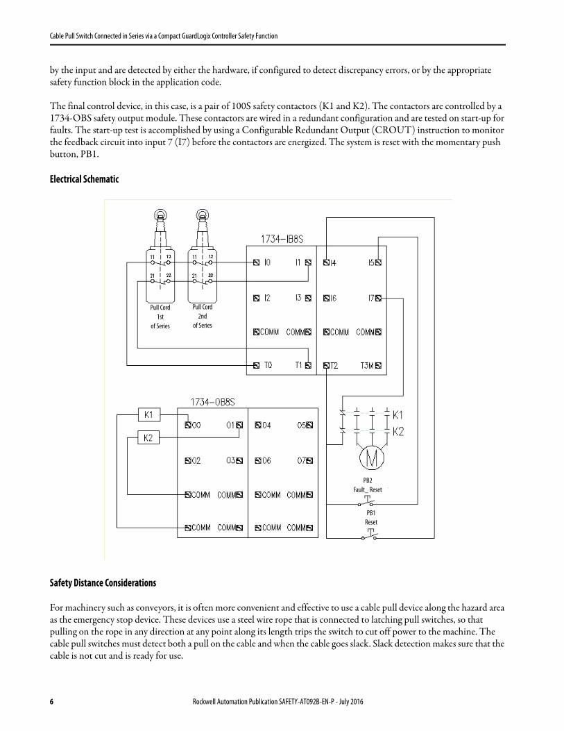
by the input and are detected by either the hardware, if configured to detect discrepancy errors, or by the appropriate safety function block in the application code.
The final control device, in this case, is a pair of 100S safety contactors (K1 and K2). The contactors are controlled by a 1734-OBS safety output module. These contactors are wired in a redundant configuration and are tested on start-up for faults. The start-up test is accomplished by using a Configurable Redundant Output (CROUT) instruction to monitor the feedback circuit into input 7 (I7) before the contactors are energized. The system is reset with the momentary push button, PB1.
Electrical Schematic
Safety Distance Considerations
For machinery such as conveyors, it is often more convenient and effective to use a cable pull device along the hazard area as the emergency stop device. These devices use a steel wire rope that is connected to latching pull switches, so that pulling on the rope in any direction at any point along its length trips the switch to cut off power to the machine. The cable pull switches must detect both a pull on the cable and when the cable goes slack. Slack detection makes sure that the cable is not cut and is ready for use.
OF SERIES OF SERIESst nd
Pull Cord
1st
of Series
Pull Cord
2nd
of Series
PB1
Reset
PB2
Fault_ Reset
6 Rockwell Automation Publication SAFETY-AT092B-EN-P - July 2016

Cable Pull Switch Connected in Series via a Compact GuardLogix Controller Safety Function
Mounting Specifications for Extended Length Models
The first and last P. bolt/eye bolt must be located as close as possible to the switch eyelet while maintaining adequate clearance (125 mm/5 in) from the cable grips to allow free movement. This arrangement provides for a straight and efficient pulling action on the switches. Additional P. bolts/eye bolts, which are spaced 2…3 m (6…9 ft) apart, help keep the perpendicular pull force, F, and distance, d, within IEC60947-5-5 specifications of 200 N (45 lb) and 400 mm (15.75 in.). We recommend using a switch at both cable ends, especially in applications with long cable runs or cable runs going around bends. This configuration helps make sure that the safety function is fulfilled upon actuation of the cable in any direction.
ISO 13850 requires that the full length of cable to be within view when the reset is turned to the run position or the machine must be inspected over the whole length of the cable, both before and after resetting. On shorter cable runs (max 10 m/32.8 ft), a Lifeline tensioner spring may be used at one end of the span. The installation must be such that the above-mentioned requirements can be met. When a spring is used, the last P. Bolt/eye bolt must be as close as possible to the spring while maintaining adequate clearance (125 mm/5 in.) from the cable grips to allow free movement. This arrangement is intended to help make sure that a pull near the end of the cable is between P. Bolts/eye bolts. This results in operation of the switch contacts, instead of only the spring moving.
Careful attention is required for the design of the installation so that the cable is not likely to become trapped or snagged. This is especially important when using a tensioner spring, because a cable snag between the location of the pull and the switch could prevent the actuation of the safety function. When the installation is complete, it is essential that a thorough functional test is made. This includes checking all types and directions of pull over the length of the cable, and checking for slack-cable tripping.
Lifeline 4 Cable Grips Steel Cable Tensioner Tensioner P. Bolts
Tension
Indicator
E-stop Button
Reset Knob
Rockwell Automation Publication SAFETY-AT092B-EN-P - July 2016 7
Cable Pull Switch Connected in Series via a Compact GuardLogix Controller Safety Function
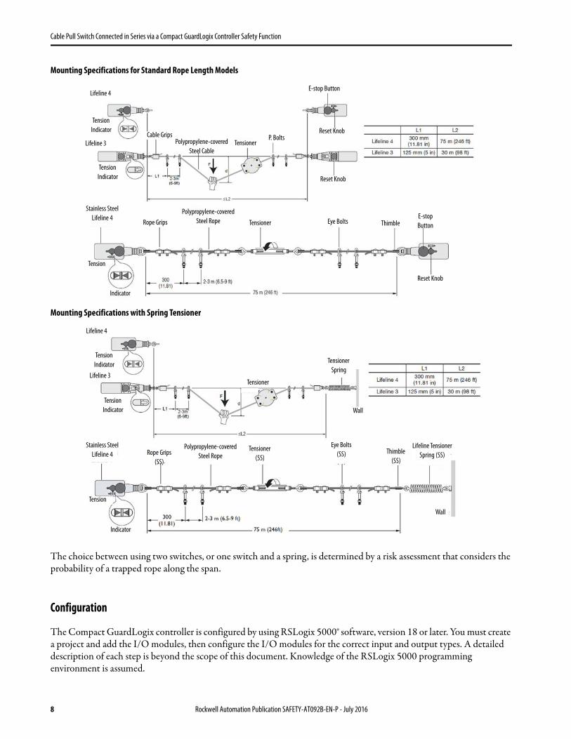
Mounting Specifications for Standard Rope Length Models
Mounting Specifications with Spring Tensioner
The choice between using two switches, or one switch and a spring, is determined by a risk assessment that considers the probability of a trapped rope along the span.
Configuration
The Compact GuardLogix controller is configured by using RSLogix 5000® software, version 18 or later. You must create a project and add the I/O modules, then configure the I/O modules for the correct input and output types. A detailed description of each step is beyond the scope of this document. Knowledge of the RSLogix 5000 programming environment is assumed.
Lifeline 4
Cable GripsTensioner
P. Bolts
E-stop Button
Reset Knob
Reset Knob
Tension
Indicator
Tension
Indicator
Polypropylene-covered
Steel Cable
Polypropylene-covered
Steel RopeE-stop
Button
Reset Knob
Tensioner
Tension
Indicator
Eye BoltsRope Grips Thimble
Stainless Steel
Lifeline 4
Lifeline 3
Lifeline 4
Lifeline 3
Tension
Indicator
Polypropylene-covered
Steel Rope
Tension
IndicatorTensioner
Spring
Tensioner
Wall
Tensioner
(SS)
Wall
Tension
Indicator
Eye Bolts
(SS) Thimble
(SS)
Stainless Steel
Lifeline 4 Rope Grips
(SS)
Lifeline Tensioner
Spring (SS)
8 Rockwell Automation Publication SAFETY-AT092B-EN-P - July 2016
Cable Pull Switch Connected in Series via a Compact GuardLogix Controller Safety Function
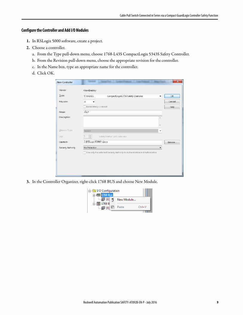
Configure the Controller and Add I/O Modules
1. In RSLogix 5000 software, create a project.2. Choose a controller.
a. From the Type pull-down menu, choose 1768-L43S CompactLogix 5343S Safety Controller.b. From the Revision pull-down menu, choose the appropriate revision for the controller.c. In the Name box, type an appropriate name for the controller.d. Click OK.
3. In the Controller Organizer, right-click 1768 BUS and choose New Module.
Rockwell Automation Publication SAFETY-AT092B-EN-P - July 2016 9

Cable Pull Switch Connected in Series via a Compact GuardLogix Controller Safety Function
4. Select the 1768-ENBT module and click Create.
5. Name the module, type its IP address, and click OK.
This example uses 192.168.1.8 as the IP address. Your IP address can differ.6. In the Controller Organizer, right-click the Ethernet network and choose New Module.
10 Rockwell Automation Publication SAFETY-AT092B-EN-P - July 2016
Cable Pull Switch Connected in Series via a Compact GuardLogix Controller Safety Function
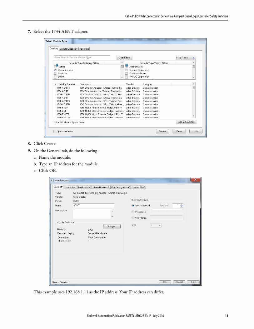
7. Select the 1734-AENT adapter.
8. Click Create.9. On the General tab, do the following:
a. Name the module.b. Type an IP address for the module.c. Click OK.
This example uses 192.168.1.11 as the IP address. Your IP address can differ.
Rockwell Automation Publication SAFETY-AT092B-EN-P - July 2016 11
Cable Pull Switch Connected in Series via a Compact GuardLogix Controller Safety Function
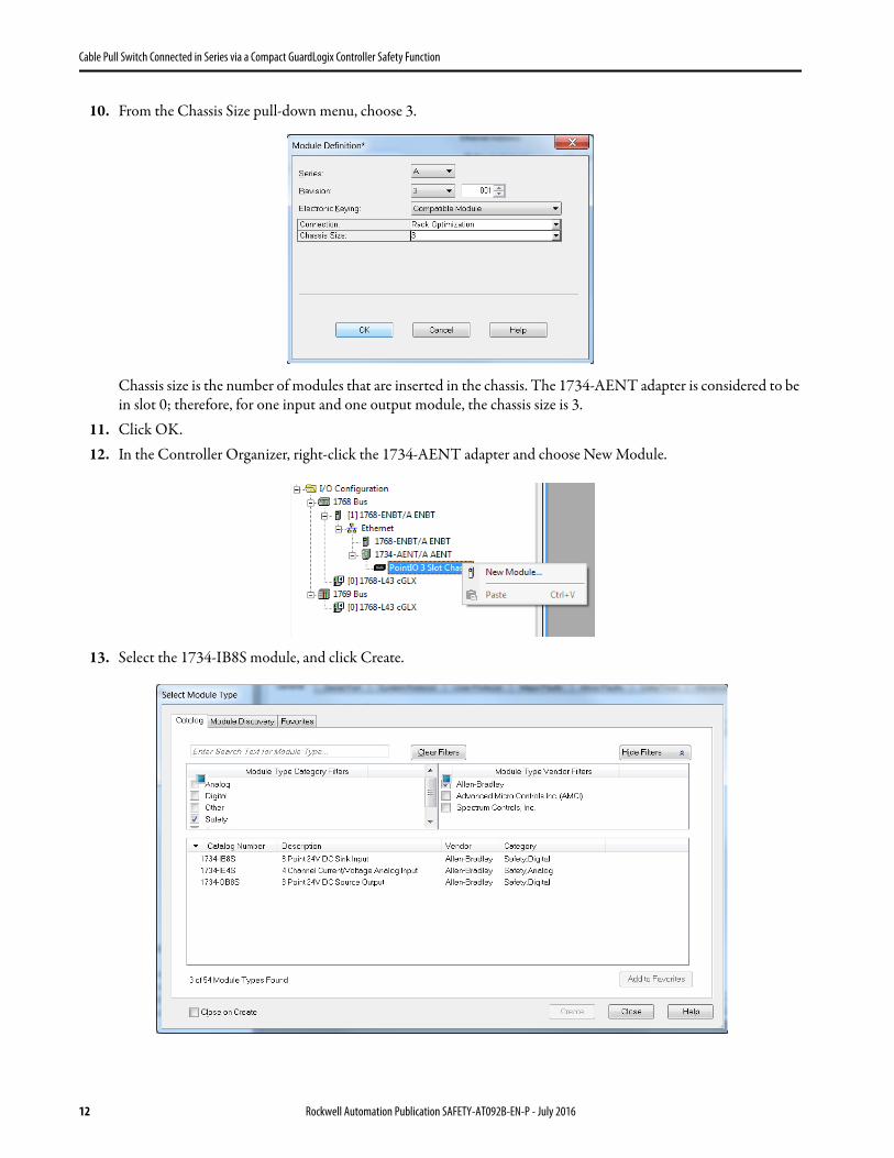
10. From the Chassis Size pull-down menu, choose 3.
Chassis size is the number of modules that are inserted in the chassis. The 1734-AENT adapter is considered to be in slot 0; therefore, for one input and one output module, the chassis size is 3.
11. Click OK.12. In the Controller Organizer, right-click the 1734-AENT adapter and choose New Module.
13. Select the 1734-IB8S module, and click Create.
12 Rockwell Automation Publication SAFETY-AT092B-EN-P - July 2016

Cable Pull Switch Connected in Series via a Compact GuardLogix Controller Safety Function
14. In the New Module dialog box, name the device CellGuard_1 and click Change.
15. From the Input Status pull-down menu, choose Combined Status-Power-Muting, and click OK.
16. Repeat steps 12…15 to add the 1734-OB8S safety output module and set Input Status to Combined Status - Readback - Power.
Rockwell Automation Publication SAFETY-AT092B-EN-P - July 2016 13
Cable Pull Switch Connected in Series via a Compact GuardLogix Controller Safety Function
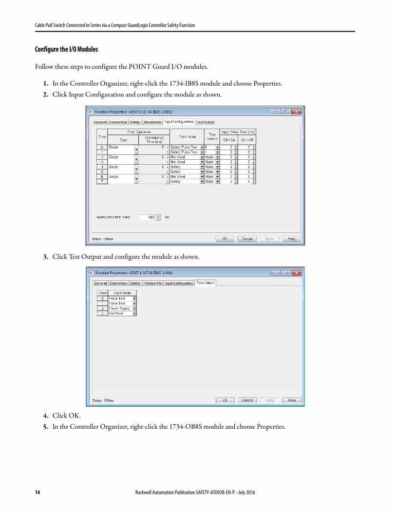
Configure the I/O Modules
Follow these steps to configure the POINT Guard I/O modules.
1. In the Controller Organizer, right-click the 1734-IB8S module and choose Properties.2. Click Input Configuration and configure the module as shown.
3. Click Test Output and configure the module as shown.
4. Click OK.5. In the Controller Organizer, right-click the 1734-OB8S module and choose Properties.
14 Rockwell Automation Publication SAFETY-AT092B-EN-P - July 2016
Cable Pull Switch Connected in Series via a Compact GuardLogix Controller Safety Function
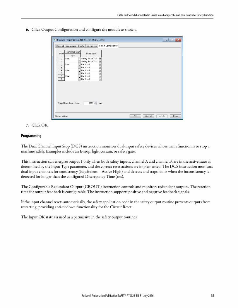
6. Click Output Configuration and configure the module as shown.
7. Click OK.
Programming
The Dual Channel Input Stop (DCS) instruction monitors dual-input safety devices whose main function is to stop a machine safely. Examples include an E-stop, light curtain, or safety gate.
This instruction can energize output 1 only when both safety inputs, channel A and channel B, are in the active state as determined by the Input Type parameter, and the correct reset actions are implemented. The DCS instruction monitors dual-input channels for consistency (Equivalent – Active High) and detects and traps faults when the inconsistency is detected for longer than the configured Discrepancy Time (ms).
The Configurable Redundant Output (CROUT) instruction controls and monitors redundant outputs. The reaction time for output feedback is configurable. The instruction supports positive and negative feedback signals.
If the input channel resets automatically, the safety application code in the safety output routine prevents outputs from restarting, providing anti-tiedown functionality for the Circuit Reset.
The Input OK status is used as a permissive in the safety output routines.
Rockwell Automation Publication SAFETY-AT092B-EN-P - July 2016 15

Cable Pull Switch Connected in Series via a Compact GuardLogix Controller Safety Function
Falling Edge Reset
ISO 13849-1 stipulates that instruction reset functions must occur on falling edge signals.
In the code that is shown above, a One Shot Falling (OSF) instruction has been added immediately preceding the Zone1_OutputEnable rung, The OSF instructions Output Bit tag is used as a reset bit for the following rung. The Zone1_OutputEnable is then used to enable the CROUT instruction.
16 Rockwell Automation Publication SAFETY-AT092B-EN-P - July 2016

Cable Pull Switch Connected in Series via a Compact GuardLogix Controller Safety Function
Calculation of the Performance Level
When properly implemented, this safety function can achieve a safety rating of Category 3, Performance Level d (CAT. 3, PLd), according to ISO 13849-1: 2008, as calculated by using the Safety Integrity Software Tool for the Evaluation of Machine Applications (SISTEMA).
When modeled in SISTEMA, each safety-cable pull switch is treated as an individual safety function and can be modeled as follows. This diagram shows one cable-pull-switch safety function.
The cable pull switch safety function can be modeled as shown in the graphic.
Because the cable pulls and contactors are electromechanical devices, certain data must be considered, including the following:
• Mean Time to Failure, dangerous (MTTFd)• Diagnostic Coverage (DCavg)• Common Cause Failure (CCF)
The functional safety evaluations of electromechanical devices include the following:• How frequently they are operated (re: MTTFd)• Whether they are effectively monitored for faults (re: DCavg)• Whether they are properly specified and installed (re: CCF)
Cable Pull 1 S1
Fault Exclusion
1734-IB8S 1734-OB8S1768-L43S
K1100S
K2100S
Subsystem 1 Subsystem 2 Subsystem 3 Subsystem 4 Subsystem 5 Subsystem 6
Cable Pull 1 S2
440L-L13137
S1
Input Logic Output
440L-L13137
S2
Fault
Exclusion
K1
100S
K2
100S
1734-IB8S 1734-OB8S1768-L43S
Subsystem 1 Subsystem 2 Subsystem 3 Subsystem 4 Subsystem 5 Subsystem 6
Rockwell Automation Publication SAFETY-AT092B-EN-P - July 2016 17

Cable Pull Switch Connected in Series via a Compact GuardLogix Controller Safety Function
Additionally, because the pulls are electromechanical devices where one mechanical actuator controls two channels, fault exclusion must be considered when calculating the safety ratings. A fault exclusion subsystem is added to SISTEMA to reflect this configuration. Each contactor controls one channel, so fault exclusion for the contactors is not necessary.
EN-ISO 13849-2:2012, Annex D, allows a fault exclusion for mechanical aspects, in this case, one actuator operating two channels of cable pull switches in accordance with IEC 60947-5-5. Because the estimated maximum number of cable pull operations (365 per year) is not considered to be excessive, this fault exclusion itself has no effect on the Category or Performance level that is achieved by the cable pull safety functions. To reflect this in the SISTEMA project, the Category and Performance Level of the fault exclusion subsystem were manually entered as Category 4 and Performance Level e (CAT. 4, PLe).
SISTEMA calculates the MTTFd by using B10d data that is provided in the Rockwell Automation SISTEMA library for the cable pulls and contactors, along with the estimated frequency of use, entered during the creation of the SISTEMA project. This example presumes that the cable pulls are operated or tested at least once a day, for a total of 365 times a year. The contactors are also operated 365 times a year.
The DCavg (60%) for the cable pulls was entered manually to take into account that the cable pulls are connected in series. Masking, due to series connection, reduces the ability of the system to detect faults.
The DCavg (99%) for the contactors is selected from the Output Device table of ISO 13849-1 Annex E, Direct Monitoring.
Verification and Validation Plan
Verification and validation play important roles in the avoidance of faults throughout the safety system design and development process. ISO 13849-2 sets the requirements for verification and validation. The standard calls for a documented plan to confirm that all safety functional requirements have been met.
Verification is an analysis of the resulting safety control system. The Performance Level (PL) of the safety control system is calculated to confirm that the system meets the required Performance Level (PLr) specified. The SISTEMA software is typically used to perform the calculations and assist with satisfying the requirements of ISO 13849-1.
Validation is a functional test of the safety control system to demonstrate that the system meets the specified requirements of the safety function. The safety control system is tested to confirm that all safety-related outputs respond appropriately to their corresponding safety-related inputs. The functional test includes normal operating conditions and potential fault injection of failure modes. A checklist is typically used to document the validation of the safety control system.
Before the GuardLogix safety system is validated, confirm that the safety system and safety application program are designed in accordance with the GuardLogix Controller Systems Safety Reference Manual, publication 1756-RM093 for GuardLogix 5560 or 1768 Compact GuardLogix controllers, or the GuardLogix 5570 and Compact GuardLogix 5370 Controller Systems Safety Reference Manual, publication 1756- RM099, and the GuardLogix Safety Application Instruction Set Safety Reference Manual, publication 1756-RM095.
18 Rockwell Automation Publication SAFETY-AT092B-EN-P - July 2016

Cable Pull Switch Connected in Series via a Compact GuardLogix Controller Safety Function
Verification and Validation Checklist
General Machinery Information
Machine Name/Model Number
Machine Serial Number
Customer Name
Test Date
Tester Name
Schematic Drawing Number
Controller Name
Safety Signature ID
Safety Network Number
RSLogix 5000 Software Version
Safety Control System Modules GuardLogix Modules Firmware Revision
GuardLogix Safety Controller 1768-L43S
CompactLogix Ethernet Bridge 1768-ENBT
POINT I/O™ Ethernet Adapter 1734-AENT
POINT I/O Input Modules 1734-IB8S
POINT I/O Output Modules 1734-OB8S
GuardLogix Safety System Wiring and Configuration Verification
Test Step Verification Pass/Fail Changes/Modifications
1Verify that the safety system is designed in accordance with the GuardLogix Controller Systems Safety Reference Manual, which is listed in the Additional Resources.
2Verify that the safety application program is designed in accordance with the GuardLogix Safety Application Instruction Set Safety Reference Manual, publication 1756-RM095.
3Visually inspect the safety system network and I/O to verify that it is wired as documented in the schematics.
4Visually inspect the RSLogix 5000 program to verify that the safety system network and I/O module configuration is configured as documented.
5Visually inspect the application program to verify that suitable safety-certified instructions are used. The logic must be readable, understandable, and testable with the aid of clear comments.
6Verify that all input devices are qualified by cycling their respective actuators. Monitor the status in the Controller Tags dialog box.
7Verify that all output devices are qualified by cycling their respective actuators. Monitor the status in the Controller Tags dialog box.
Normal Operation Verification - The GuardLogix safety system responds properly to all normal Start, Stop, and Reset inputs.
Test Step Verification Pass/Fail Changes/Modifications
1Initiate a Start command. Both contactors energize for a normal machine run condition. Verify proper machine-status indication and safety application program indication.
2Initiate a Stop command. Both contactors de-energize for a normal machine stop condition. Verify proper machine-status indication and safety application program indication.
Rockwell Automation Publication SAFETY-AT092B-EN-P - July 2016 19
Cable Pull Switch Connected in Series via a Compact GuardLogix Controller Safety Function
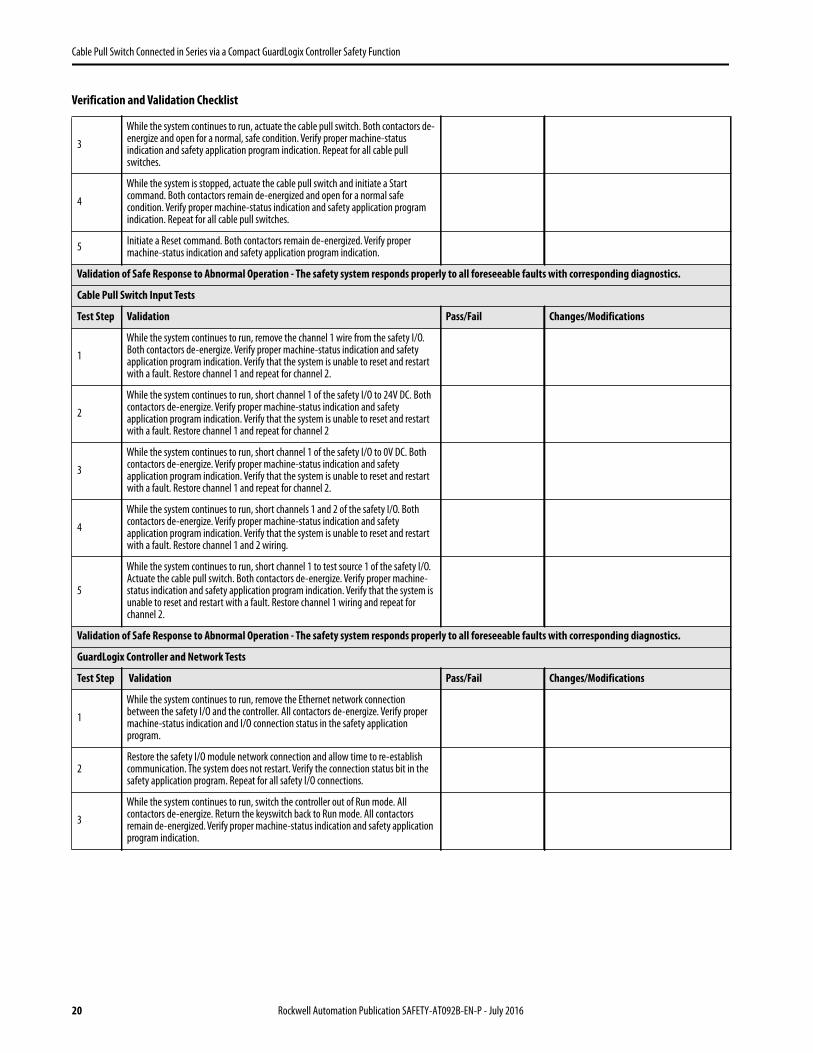
3
While the system continues to run, actuate the cable pull switch. Both contactors de-energize and open for a normal, safe condition. Verify proper machine-status indication and safety application program indication. Repeat for all cable pull switches.
4
While the system is stopped, actuate the cable pull switch and initiate a Start command. Both contactors remain de-energized and open for a normal safe condition. Verify proper machine-status indication and safety application program indication. Repeat for all cable pull switches.
5Initiate a Reset command. Both contactors remain de-energized. Verify proper machine-status indication and safety application program indication.
Validation of Safe Response to Abnormal Operation - The safety system responds properly to all foreseeable faults with corresponding diagnostics.
Cable Pull Switch Input Tests
Test Step Validation Pass/Fail Changes/Modifications
1
While the system continues to run, remove the channel 1 wire from the safety I/O. Both contactors de-energize. Verify proper machine-status indication and safety application program indication. Verify that the system is unable to reset and restart with a fault. Restore channel 1 and repeat for channel 2.
2
While the system continues to run, short channel 1 of the safety I/O to 24V DC. Both contactors de-energize. Verify proper machine-status indication and safety application program indication. Verify that the system is unable to reset and restart with a fault. Restore channel 1 and repeat for channel 2
3
While the system continues to run, short channel 1 of the safety I/O to 0V DC. Both contactors de-energize. Verify proper machine-status indication and safety application program indication. Verify that the system is unable to reset and restart with a fault. Restore channel 1 and repeat for channel 2.
4
While the system continues to run, short channels 1 and 2 of the safety I/O. Both contactors de-energize. Verify proper machine-status indication and safety application program indication. Verify that the system is unable to reset and restart with a fault. Restore channel 1 and 2 wiring.
5
While the system continues to run, short channel 1 to test source 1 of the safety I/O. Actuate the cable pull switch. Both contactors de-energize. Verify proper machine-status indication and safety application program indication. Verify that the system is unable to reset and restart with a fault. Restore channel 1 wiring and repeat for channel 2.
Validation of Safe Response to Abnormal Operation - The safety system responds properly to all foreseeable faults with corresponding diagnostics.
GuardLogix Controller and Network Tests
Test Step Validation Pass/Fail Changes/Modifications
1
While the system continues to run, remove the Ethernet network connection between the safety I/O and the controller. All contactors de-energize. Verify proper machine-status indication and I/O connection status in the safety application program.
2Restore the safety I/O module network connection and allow time to re-establish communication. The system does not restart. Verify the connection status bit in the safety application program. Repeat for all safety I/O connections.
3
While the system continues to run, switch the controller out of Run mode. All contactors de-energize. Return the keyswitch back to Run mode. All contactors remain de-energized. Verify proper machine-status indication and safety application program indication.
Verification and Validation Checklist
20 Rockwell Automation Publication SAFETY-AT092B-EN-P - July 2016

Cable Pull Switch Connected in Series via a Compact GuardLogix Controller Safety Function
Additional Resources
These documents contain more information about related products from Rockwell Automation.
You can view or download publications at http://www.rockwellautomation.com/literature/. To order paper copies of technical documentation, contact your local Allen-Bradley distributor or Rockwell Automation sales representative.
Validation of Safe Response to Abnormal Operation - The safety system responds properly to all foreseeable faults with corresponding diagnostics.
Safety Contactor Output Tests
Test Step Verification and Validation Pass/Fail Changes/Modifications
1Initiate a Start command. Both contactors energize for a normal machine run condition. Verify proper machine-status indication and safety application program indication.
2
While the system continues to run, remove the contactor feedback from the safetyI/O. All contactors remain energized. Initiate a Stop command and attempt a Reset command. The system does not restart or reset. Verify proper machine-status indication and safety application program indication.
3
While the system continues to run, short the contactor feedback to the safety I/O. All contactors remain energized. Initiate a Stop command and attempt a Reset command. The system does not restart or reset. Verify proper machine-status indication and safety application program indication.
Resource Description
Compact GuardLogix Controllers User Manual, publication 1768-UM002Provides information on how to configure, operate, and maintain Compact GuardLogix controllers.
POINT Guard I/O Safety Modules User Manual, publication 1734-UM013Provides information on how to install, configure, and operate POINT Guard I/O modules.
GuardLogix Controller Systems Safety Reference Manual, publication 1756-RM093Contains detailed requirements on how to achieve and maintain safety ratings with the GuardLogix 5560 or 1768 Compact GuardLogix controller system.
GuardLogix Safety Application Instruction Set Safety Reference Manual, publication 1756-RM095
Describes the Rockwell Automation GuardLogix Safety Application Instruction Set. Provides instructions on how to design, program, or troubleshoot safety applications that use GuardLogix controllers.
GuardLogix 5570 and Compact GuardLogix 5370 Controller Systems Safety Reference Manual, publication 1756-RM099
Describes the GuardLogix 5570 and Compact GuardLogix 5370 controller system. Provides instructions on how to develop, operate, or maintain a GuardLogix 5570 and Compact GuardLogix 5370 controller-based safety system that uses the Studio 5000 Logix Designer® application.
Safety Accelerator Toolkit Quick Start, publication IASIMP-QS005Provides a step-by-step guide on how to use the design, programming, and diagnostic tools in the Safety Accelerator Toolkit.
Safety Products Catalog–Operator Interface section, publication S117-CA504 Provides an overview of the operator interface of LifeLine 4 cable pull switches.
Industrial Automation Wiring and Grounding Guidelines, publication 1770-4.1 Provides general guidelines on how to install a Rockwell Automation industrial system.
Safety Products Catalog, publication S117-CA001
Website http://www.rockwellautomation.com/rockwellautomation/catalogs/overview.page
Provides information about Rockwell Automation safety products.
Product Certifications website, http://www.rockwellautomation.com/global/certification/overview.page
Provides declarations of conformity, certificates, and other certification details.
Verification and Validation Checklist
Rockwell Automation Publication SAFETY-AT092B-EN-P - July 2016 21

Allen-Bradley, CompactLogix, Compact GuardLogix, GuardLogix, Lifeline, LISTEN. THINK. SOLVE, POINT Guard I/O, POINT I/O, RSLogix, RSLogix 5000, Rockwell Automation, Rockwell Software, SensaGuard, Stratix 2000, and
Studio 5000 Logix Designer are trademarks of Rockwell Automation, Inc.
Trademarks not belonging to Rockwell Automation are property of their respective companies.
CIP Safety and EtherNet/IP are trademarks of ODVA, Inc.
Publication SAFETY-AT092B-EN-P - July 2016
Rockwell Automation SupportUse the following resources to access support information.
Documentation FeedbackYour comments will help us serve your documentation needs better. If you have any suggestions on how to improve this document, complete the How Are We Doing? form at http://literature.rockwellautomation.com/idc/groups/literature/documents/du/ra-du002_-en-e.pdf.
Technical Support Center Knowledgebase Articles, How-to Videos, FAQs, Chat, User Forums, and Product Notification Updates.
www.rockwellautomation.com/knowledgebase
Local Technical Support Phone Numbers Locate the phone number for your country.www.rockwellautomation.com/global/support/get-support-now.page
Direct Dial CodesFind the Direct Dial Code for your product. Use the code to route your call directly to a technical support engineer.
www.rockwellautomation.com/global/support/direct-dial.page
Literature Library Installation Instructions, Manuals, Brochures, and Technical Data.
www.rockwellautomation.com/literature
Product Compatibility and Download Center (PCDC)
Get help determining how products interact, check features and capabilities, and find associated firmware.
www.rockwellautomation.com/global/support/pcdc.page
Rockwell Otomasyon Ticaret A.Ş., Kar Plaza İş Merkezi E Blok Kat:6 34752 İçerenköy, İstanbul, Tel: +90 (216) 5698400
Rockwell Automation maintains current product environmental information on its website at http://www.rockwellautomation.com/rockwellautomation/about-us/sustainability-ethics/product-environmental-compliance.page.
For more information onSafety Function Capabilities, visit:http://marketing.rockwellautomation.com/safety/en/safety_functions
Supersedes Publication SAFETY-AT092A-EN-P - August 2013 Copyright © 2016 Rockwell Automation, Inc. All rights reserved. Printed in the U.S.A.