Embed Size (px)
Citation preview

DescriptionEaton uses its Cooper Power™ series VACpac™ vacuum switchgear to switch load, loop, capacitor, cable charging and magnetizing currents. VACpac switchgear may be installed on distribution systems having voltage ratings lower than nameplate and retain all other ratings. VACpac switchgear vacuum bottle interrupters feature the highest duty cycle of any distribution system, making it ideally suited for automated applications that require a large number of switching operations.
Note:N Separable connectors that comply with the IEEE Std 386™-2006 standard are required for terminating cables to VACpac switchgear. This permits the implementation of local or industry established safety procedures by qualified personnel for testing, visibly isolating and/or grounding high voltage de-energized cables when maintenance of cables or associated equipment is required after a switching operation. In some cases, local conditions may dictate that supplementary equipment be used to perform these procedures.
Eaton's switch technology in VACpac switchgear provides the distribution engineer with the ultimate in modern switchgear design. It features the proven technology of vacuum interrupters supported by more than five decades of successful VACpac switchgear field experience.
The unit was designed specifically with safety in mind. The advantages of a non-catastrophic failure mode which vacuum possesses cannot be realized without the determination of a total design which involves the insulating medium. To this end, the original designs which included oil insulation were abandoned in favor of SF6 insulating gas. This was in keeping with the concept of providing a controlled non-combustible insulating medium within the tank. There have been no eventful failures of this equipment to date.
The use of SF6 insulating gas has provided additional benefits in the way of compactness and light weight. Based on the increased costs of floor space, there is a greater reluctance on the part of the user to give up this valuable area for housing large electrical switchgear. VACpac switchgear space requirements are minimal and may be mounted from walls or ceilings. Special building requirements for liquid containment or combustibles would not apply to an SF6 insulating medium. Compactness also permits the use of VACpac switchgear in manholes or vaults, since installation is possible through the access openings.
VACpac™ vacuum switchgear
Underground Distribution SwitchgearCA285003EN
Effective January 2016 Supersedes 285-30 April 2014
COOPER POWERSERIES
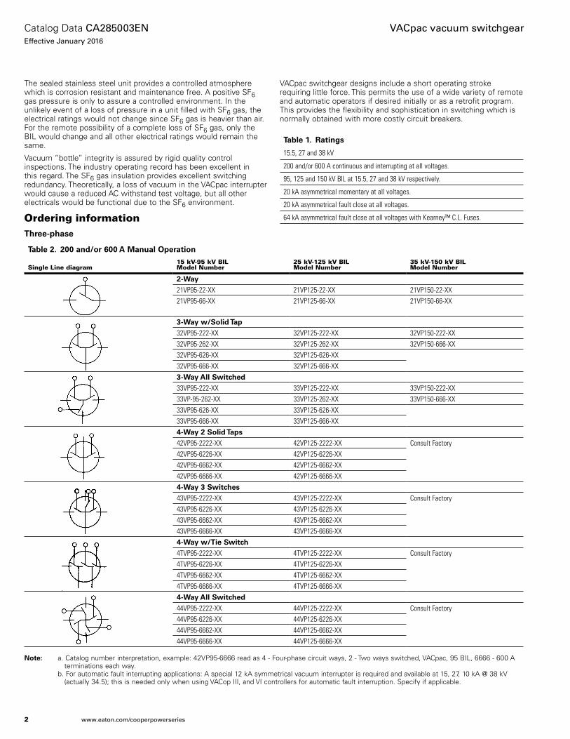
The sealed stainless steel unit provides a controlled atmosphere which is corrosion resistant and maintenance free. A positive SF6 gas pressure is only to assure a controlled environment. In the unlikely event of a loss of pressure in a unit filled with SF6 gas, the electrical ratings would not change since SF6 gas is heavier than air. For the remote possibility of a complete loss of SF6 gas, only the BIL would change and all other electrical ratings would remain the same.
Vacuum “bottle” integrity is assured by rigid quality control inspections. The industry operating record has been excellent in this regard. The SF6 gas insulation provides excellent switching redundancy. Theoretically, a loss of vacuum in the VACpac interrupter would cause a reduced AC withstand test voltage, but all other electricals would be functional due to the SF6 environment.
VACpac switchgear designs include a short operating stroke requiring little force. This permits the use of a wide variety of remote and automatic operators if desired initially or as a retrofit program. This provides the flexibility and sophistication in switching which is normally obtained with more costly circuit breakers.
Ordering informationThrtt-phast
Note:N a. Catalog number interpretation, example: 42VP95-6666 read as 4 - Four-phase circuit ways, 2 - Two ways switched, VACpac, 95 BIL, 6666 - 600 A terminations each way. b. For automatic fault interrupting applications: A special 12 kA symmetrical vacuum interrupter is required and available at 15, 27, 10 kA @ 38 kV (actually 34.5); this is needed only when using VACop III, and VI controllers for automatic fault interruption. Specify if applicable.
Tablt 1. Raoings
15.5, 27 and 38 kV
200 and/or 600 A continuous and interrupting at all voltages.
95, 125 and 150 kV BIL at 15.5, 27 and 38 kV respectively.
20 kA asymmetrical momentary at all voltages.
20 kA asymmetrical fault close at all voltages.
64 kA asymmetrical fault close at all voltages with Kearney™ C.L. Fuses.
Tablt 2. 200 and/Nr 600 A Manual OptraoiNn
Single Line diagram15 kV-95 kV BILModel Number
25 kV-125 kV BILModel Number
35 kV-150 kV BILModel Number
2-Way21VP95-22-XX 21VP125-22-XX 21VP150-22-XX21VP95-66-XX 21VP125-66-XX 21VP150-66-XX
3-Way w/SNlid Tap32VP95-222-XX 32VP125-222-XX 32VP150-222-XX32VP95-262-XX 32VP125-262-XX 32VP150-666-XX32VP95-626-XX 32VP125-626-XX32VP95-666-XX 32VP125-666-XX3-Way All Swiochtd33VP95-222-XX 33VP125-222-XX 33VP150-222-XX33VP-95-262-XX 33VP125-262-XX 33VP150-666-XX33VP95-626-XX 33VP125-626-XX33VP95-666-XX 33VP125-666-XX4-Way 2 SNlid Taps42VP95-2222-XX 42VP125-2222-XX Consult Factory42VP95-6226-XX 42VP125-6226-XX42VP95-6662-XX 42VP125-6662-XX42VP95-6666-XX 42VP125-6666-XX4-Way 3 Swiochts43VP95-2222-XX 43VP125-2222-XX Consult Factory43VP95-6226-XX 43VP125-6226-XX43VP95-6662-XX 43VP125-6662-XX43VP95-6666-XX 43VP125-6666-XX4-Way w/Tit Swioch4TVP95-2222-XX 4TVP125-2222-XX Consult Factory4TVP95-6226-XX 4TVP125-6226-XX4TVP95-6662-XX 4TVP125-6662-XX4TVP95-6666-XX 4TVP125-6666-XX4-Way All Swiochtd44VP95-2222-XX 44VP125-2222-XX Consult Factory44VP95-6226-XX 44VP125-6226-XX44VP95-6662-XX 44VP125-6662-XX44VP95-6666-XX 44VP125-6666-XX
2
Catalog Data CA285003ENEffective January 2016
VACpac vacuum switchgear
www.eaton.com/cooperpowerseries

Singlt-phast
NNotse: a. Catalog number interpretation, example: 121VP125-22 read as 1 - single-phase switch, VACpac, 125 BIL, 22-200 A terminations.
b. For automatic fault interrupting applications: A special 12 kA symmetrical vacuum interrupter is required and available at 15, 27, 10 kA @ 38 kV (actually 34.5); this is needed only when using VACop III, and VI controllers for automatic fault interruption. Specify if applicable.
Tablt 3. 200 and/Nr 600 A Manual OptraoiNn
Single Line Diagram15 kV-95 kV BILCatalog Number
25 kV-125 kV BILCatalog Number
35 kV-150 kV BILCatalog Number
2-Way
121VP95-22-XX 121VP125-22-XX 121VP150-22-XX
121VP95-66-XX 121VP125-66-XX 121VP150-66-XX
3-Way 1 Swiochtd Tap
131VP95-222-XX 131VP125-222-XX 131VP150-222-XX
131VP95-262-XX 131VP125-262-XX 131VP150-262-XX
131VP95-626-XX 131VP125-626-XX 131VP150-626-XX
131VP95-666-XX 131VP125-666-XX 131VP150-666-XX
3-Way w/SNlid Tap
132VP95-222-XX 132VP125-222-XX 132VP150-222-XX
132VP95-262-XX 132VP125-262-XX 132VP150-262-XX
132VP95-626-XX 132VP125-626-XX 132VP150-626-XX
132VP95-666-XX 132VP125-666-XX 132VP150-666-XX
3-Way All Swiochtd
133VP95-222-XX 133VP125-222-XX 133VP150-222-XX
133VP95-262-XX 133VP125-262-XX 133VP150-262-XX
133VP95-626-XX 133VP125-626-XX 133VP150-626-XX
133VP95-666-XX 133VP125-666-XX 133VP150-666-XX
3
Catalog Data CA285003ENEffective January 2016
VACpac vacuum switchgear
www.eaton.com/cooperpowerseries
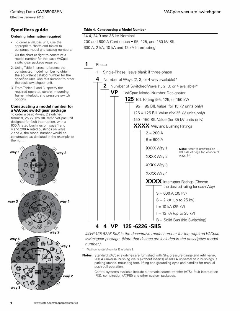
Specifiers guideOrdtring infNrmaoiNn rtquirtd
• To order a VACpac unit, use the appropriate charts and tables to construct model and catalog numbers:
1. Us the chart at right to construct a model number for the basic VACpac switchgear package required.
2. Using Table 1, cross reference the constructed model number to obtain the equivalent catalog number for the specified unit. Use this number to order the basic switchgear unit.
3. From Tables 2 and 3, specify the required operator, control, mounting frame, interlock, and pressure switch options.
CNnsorucoing a mNdtl numbtr fNr a VACpac swiochgtar packagtTo order a basic 4-way, 2 switched terminal, 25 kV 125 BIL rated VACpac unit designed for fault interruption, with a 600 A rated bushings on ways 1 and 4 and 200 A rated bushings on ways 2 and 3, the model number would be constructed as depicted in the example to the right.
Tablt 4. CNnsorucoing a MNdtl Numbtr
1 Phase
1 = Single-Phase, leave blank if three-phase
4 Number of Ways (2, 3, or 4 way available)*
2 Number of Switched Ways (1, 2, 3, or 4 available)*
VP VACpac Model Number Designator
125 BIL Rating (95, 125, or 150 kV)
95 = 95 BIL Value (for 15 kV units only)
125 = 125 BIL Value (for 25 kV units only)
150 - 150 BIL Value (for 35 kV units only)
XXXX Way and Bushing Ratings
2 = 200 A
6 = 600 A
XXXX Way 1
XXXX Way 2
XXXX Way 3
XXXX Way 4
XXXX Interrupter Ratings (Choose the desired rating for each Way)
S = 600 A (35 kV)
S = 2 kA (up to 25 kV)
I = 10 kA (35 kV)
I = 12 kA (up to 25 kV)
B = Solid Bus (No Switching)
4 4 VP 125 -6226 -SIIS
44VP-125-6226-SIIS is the descriptive model number for the required VACpac switchgear package. (Note that dashes are included in the descriptive model number.)
* Maximum number of ways for 35 kV units is 3.
Notse:N Standard VACpac switches are furnished with SF6 pressure gauge and refill valve, 200 A universal bushing wells (without inserts) or 600 A universal stud bushings, a parking stands, mounting feet, lifting and grounding eyes and handles for manual push-pull operation.
Control systems available include automatic source transfer (ATS), fault interruption (FIS), combination (ATFIS) and other custom packages.
14.4, 24.9 and 35 kV Nominal200 and 600 A Continuous • 95, 125, and 150 kV BIL 600 A, 2 kA, 10 kA and 12 kA Interrupting
Note:N Refer to drawings on left side of page for location of ways 1-4.
way 1way 3
way 2
way 1
way 2
way 3
way 4
way 1 way 2
4
Catalog Data CA285003ENEffective January 2016
VACpac vacuum switchgear
www.eaton.com/cooperpowerseries
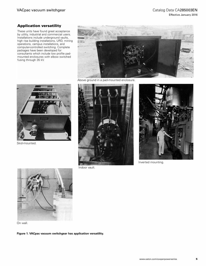
Application versatilityThese units have found great acceptance by utility, industrial and commercial users. Installations include underground vaults, high rise building installations, URD, mining operations, campus installations, and computer-controlled switching. Complete packages have been developed for consultants which include low profile pad-mounted enclosures with elbow switched fusing through 35 kV.
Figurt 1. VACpac vacuum swiochgtar has applicaoiNn vtrsaoilioy.
Above ground in a pad-mounted enclosure.
Skid-mounted.
Indoor vault.
Inverted mounting.
On wall.
5
Catalog Data CA285003ENEffective January 2016
VACpac vacuum switchgear
www.eaton.com/cooperpowerseries

Figurt 2. VACpac vacuum swiochgtar can bt ustd in a varitoy Nf uoilioy, indusorial, and cNmmtrcial applicaoiNns.
Suspended from ceiling.
Manhole, drop thru access, remote mechanical switching with VACop IV operator. Mechanical operator (top photo) with drop through access into vault (bottom photo).
Maintenance free fiberglass enclosure.
Suspended between vault walls for ground level hotstick operation.
Retrofit of existing metal enclosures.
6
Catalog Data CA285003ENEffective January 2016
VACpac vacuum switchgear
www.eaton.com/cooperpowerseries

Interrupter design characteristicsVacuum arc interruption at high voltages became a commercial realization in the 1960s. Technical refinements created a vacuum atmosphere that does not degenerate from switching operations.
The current in any arc is carried by highly ionized, extremely hot gases. In air, oil, and SF6 interrupters, this gas is created by the decomposition of the interrupting medium. In a vacuum interrupter, this gas is composed almost entirely of metal vapor evaporated from the contacts. As a result, very little arcing takes place and the dielectric strength is recovered in a matter of microseconds. This rapid recovery of dielectric strength accounts for vacuums outstanding current interrupting ability and its ability to withstand high rates of rise of recovery voltages.
Due to this high dielectric recovery, little contact separation (approximately 3/8”) is required and compact, low-powered actuating mechanisms are employed. The low energy arc produced in the vacuum interrupter is quickly extinguished and controlled by contact design. This results in very little contact material being vaporized and the sealed ceramic interrupter housing remains permanently clean.
To operate the switch requires only a short (3”) push to close - pull to open. The mechanism is an overtoggle type to provide a quick and positive make-and-break action. VACpac switchgear can be operated manually or automatically with a choice of controls and accessories. All VACpac switchgear controls and components are top mounted. When using automatic controls, positive current interruption can be accomplished in a maximum of 5 cycles; this includes arcing and mechanical operating times.
ConstructionVACpac switchgear are of completely welded construction to provide a sealed tank enclosure. The tank is made from corrosion resistant 300 series stainless steel. The operating shaft is of stainless steel and the handle is of brass. A standard Schrader filler valve is used to fill the tank with inert non-corrosive sulfur hexafluoride insulating gas. A pressure gauge is provided to monitor internal pressure conditions. The tanks are provided with lifting eyes and hold down installation tabs.
Figurt 3. VACpac inotrrupotr dtsign characotrisoics.
Figurt 4. VACpac swiochgtar cNnsorucoiNn.
Movable Electrical Terminal
Vacuum Chamber
Flexible Metallic Bellows Assembly
Insulating Vacuum Envelope
Electrical Contacts
Metal Vapor Condensing ShieldStationary Electrical Terminal
7
Catalog Data CA285003ENEffective January 2016
VACpac vacuum switchgear
www.eaton.com/cooperpowerseries

The vacuum interrupter contacts are housed within a ceramic “bottle.” A vacuum of 10-7 torr is pulled in the “bottle” and the unit is tested for vacuum at least four (4) separate times before shipment to the field. This testing is provided to ensure a life in excess of twenty (20) years on the “bottle.”
The interrupter contacts are made from a copper alloy to prevent contact welding. The alloy material has a high vapor pressure which is effectively used to reduce “current chopping.”
A stainless steel vapor condensing shield in the “bottle” performs the function of trapping all the metal vapor produced by the arc. This serves to keep the inner surface of the “bottle” free of any possible contamination and preserves the steady state electrical ratings.
A stainless steel bellows within the “bottle” is attached to a movable external terminal and permits the contacts to be switched while maintaining a vacuum. The bellows has an independent protective shield and has a fatigue life of 10,000 operations. Contact separation in the open position is approximately 3/8”.
The movable vacuum “bottle” terminal is secured to a patented toggle mechanism support casting. This mechanism provides for quick make, quick-break switching with a positive over toggle travel. The operator switching force required is approximately 35 lbs.
An external operating shaft is used to perform the switching function; push to close, pull to open. The tank seal for this linear switching motion is obtained by means of a movable stainless steel bellows which is welded to the tank. A secondary seal system is used to ensure the integrity of this bellows. A locking hasp is provided to padlock the operating handle in the open or closed switched position.
Welded universal bushing wells are used to terminate 200 A circuit ways and welded universal stud bushings are used for 600 A ways. These will accept standard 200 and 600 A rubber connectors that meet the IEEE Std 386™-2006 standard. All operating equipment is top mounted on the VACpac switchgear tank. Appropriate nameplate and schematic diagrams are secure to the tank top.
8
Catalog Data CA285003ENEffective January 2016
VACpac vacuum switchgear
www.eaton.com/cooperpowerseries
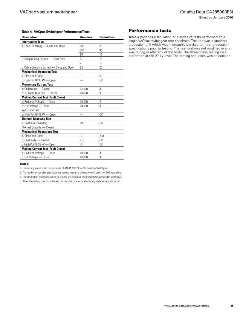
Performance testsTable 4 provides a tabulation of a series of tests performed on a single VACpac switchgear test specimen. The unit was a standard production unit which was thoroughly checked to meet production specifications prior to testing. The test unit was not modified in any way during or after any of the tests. The three-phase testing was performed at the 27 kV level. The testing sequence was as outlined.
Tablt 4. VACpac Swiochgtar PtrfNrmanct Ttsos
Description Amperes Operations
Interrupting Testsa. Load Switching — Close and Open 600 20
300 3050 10
b. Magnetizing Current — Open Only 21 107 10
c. Cable Charging Current — Close and Open 25 20Mechanical Operation Testa. Close and Open -0- 50b. High Pot @ 30 kV — Open — OKMomentary Current Testa. Calibration — Closed 12,000 3b. 10 Cycle Duration — Closed 20,000 9Making Current Test (Fault Close)a. Reduced Voltage — Close 10,000 2b. Full Voltage — Close 20,000 3Withstand Testa. High Pot @ 42 kV — Open — OKThermal Runaway Testa. Continuous Loading 600 OKThermal Stability — ClosedMechanical Operations Testa. Close and Open -0- 200b. Continuity — Closed -0- OKc. High Pot @ 38 kV — Open -0- OKMaking Current Test (Fault Close)a. Reduced Voltage — Close 10,000 3b. Full Voltage — Close 20,000 3
NNotse:
a. This testing exceeds the requirements of ANSI® C37.71 for Submersible Switchgear.
b. The number of switching functions for various circuit conditions were in excess of 360 operations.
c. The 6 fault close operations exceed by a factor of 2 maximum requirements for submersible switchgear.
d. When the testing was discontinued, the test switch was yet electrically and mechanically sound.
9
Catalog Data CA285003ENEffective January 2016
VACpac vacuum switchgear
www.eaton.com/cooperpowerseries
InstallationVACpac switchgear are provided with hold down tabs for mounting purposes. VACpac switchgear are not position oriented and may be mounted on the floor, wall, or ceiling. VACpac switchgear weights may be obtained from “Physical Specifications” (see page 10). It is suggested that VACpac switchgear be bolted in place in submersible environments or the unit will float if the vault or manhole becomes flooded.
Cable terminal attachments to the VACpac switchgear are accomplished with rubber type connectors that meet the IEEE Std 386™-2006 standard. Standard VACpac switchgear are provided with universal bushing wells at 200 A which will accept bushing inserts and universal stud connectors at 600 A which will accept Eaton's Cooper Power series BOL-T™ deadbreak connectors. These terminations provide for circuit testing, circuit isolation (visible gas) and/or cable grounding.
Paper insulated lead covered (PILC) type cables require special terminations. Consult factory for details.
For long life operations, cable training and terminating should be carefully planned. Lead sheath cables in ducts may be subjected to movement from repeated cyclic loading; if not properly terminated this cable movement could impose excessive stresses on the termination. Extensive unsupported cable weight can also create an excessive strain on the termination. Finally, a momentary fault current can cause cables to produce a “whip action” on unsupported cables which could transmit a shock wave to the terminations. For these reasons, the following recommendations should be considered when terminating cables to equipment.
1. Use URD type concentric cables to terminate at the elbows where possible.
2. Train the cables to enter the elbows along the center axis of the elbow cable cavity as closely as possible.
3. Support the cable 3’ to 4’ from the elbow termination or as specified by the elbow supplier.
4. When solid dielectric lead sheath cables in ducts are used, circle the manhole with the cable before terminating at the switch. This will provide an expansion “U” bend for this cable type.
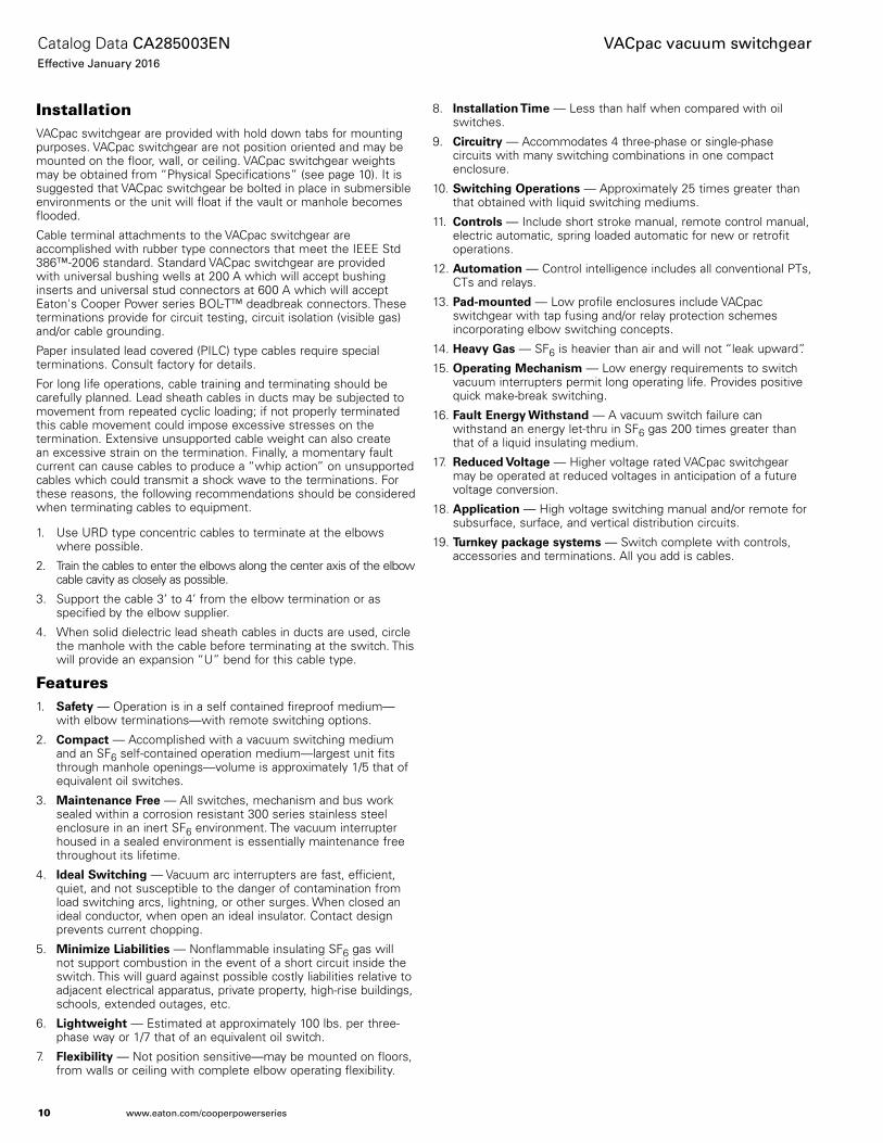
Features1. Saftoy — Operation is in a self contained fireproof medium—
with elbow terminations—with remote switching options.
2. CNmpaco — Accomplished with a vacuum switching medium and an SF6 self-contained operation medium—largest unit fits through manhole openings—volume is approximately 1/5 that of equivalent oil switches.
3. Mainotnanct Frtt — All switches, mechanism and bus work sealed within a corrosion resistant 300 series stainless steel enclosure in an inert SF6 environment. The vacuum interrupter housed in a sealed environment is essentially maintenance free throughout its lifetime.
4. Idtal Swioching — Vacuum arc interrupters are fast, efficient, quiet, and not susceptible to the danger of contamination from load switching arcs, lightning, or other surges. When closed an ideal conductor, when open an ideal insulator. Contact design prevents current chopping.
5. Minimizt Liabilioits — Nonflammable insulating SF6 gas will not support combustion in the event of a short circuit inside the switch. This will guard against possible costly liabilities relative to adjacent electrical apparatus, private property, high-rise buildings, schools, extended outages, etc.
6. Lighowtigho — Estimated at approximately 100 lbs. per three-phase way or 1/7 that of an equivalent oil switch.
7. Fltxibilioy — Not position sensitive—may be mounted on floors, from walls or ceiling with complete elbow operating flexibility.
8. InsoallaoiNn Timt — Less than half when compared with oil switches.
9. Circuiory — Accommodates 4 three-phase or single-phase circuits with many switching combinations in one compact enclosure.
10. Swioching OptraoiNns — Approximately 25 times greater than that obtained with liquid switching mediums.
11. CNnorNls — Include short stroke manual, remote control manual, electric automatic, spring loaded automatic for new or retrofit operations.
12. AuoNmaoiNn — Control intelligence includes all conventional PTs, CTs and relays.
13. Pad-mNunotd — Low profile enclosures include VACpac switchgear with tap fusing and/or relay protection schemes incorporating elbow switching concepts.
14. Htavy Gas — SF6 is heavier than air and will not “leak upward”.
15. Optraoing Mtchanism — Low energy requirements to switch vacuum interrupters permit long operating life. Provides positive quick make-break switching.
16. Faulo Entrgy Wiohsoand — A vacuum switch failure can withstand an energy let-thru in SF6 gas 200 times greater than that of a liquid insulating medium.
17. Rtductd VNloagt — Higher voltage rated VACpac switchgear may be operated at reduced voltages in anticipation of a future voltage conversion.
18. ApplicaoiNn — High voltage switching manual and/or remote for subsurface, surface, and vertical distribution circuits.
19. Turnkty packagt sysotms — Switch complete with controls, accessories and terminations. All you add is cables.
10
Catalog Data CA285003ENEffective January 2016
VACpac vacuum switchgear
www.eaton.com/cooperpowerseries
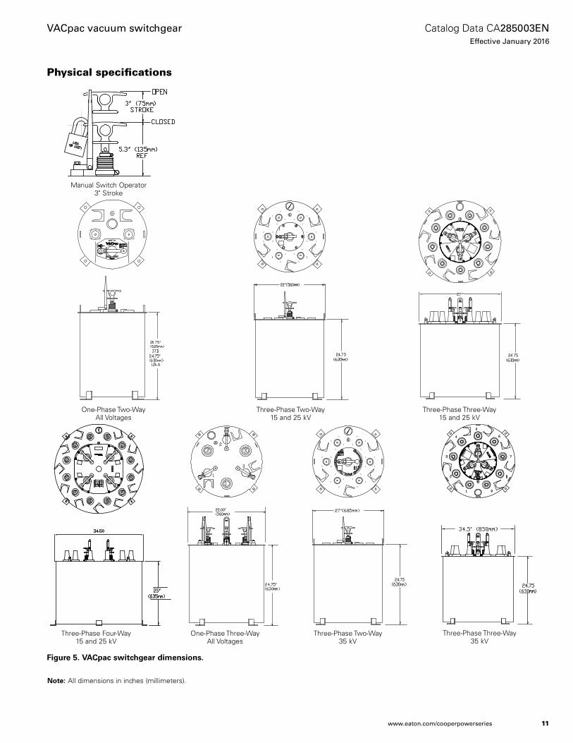
Physical specifications
Figurt 5. VACpac swiochgtar dimtnsiNns.
Note:N All dimensions in inches (millimeters).
One-Phase Two-Way All Voltages
Three-Phase Two-Way 15 and 25 kV
Three-Phase Four-Way 15 and 25 kV
One-Phase Three-Way All Voltages
Three-Phase Two-Way 35 kV
Three-Phase Three-Way 35 kV
Three-Phase Three-Way 15 and 25 kV
Manual Switch Operator 3" Stroke
11
Catalog Data CA285003ENEffective January 2016
VACpac vacuum switchgear
www.eaton.com/cooperpowerseries
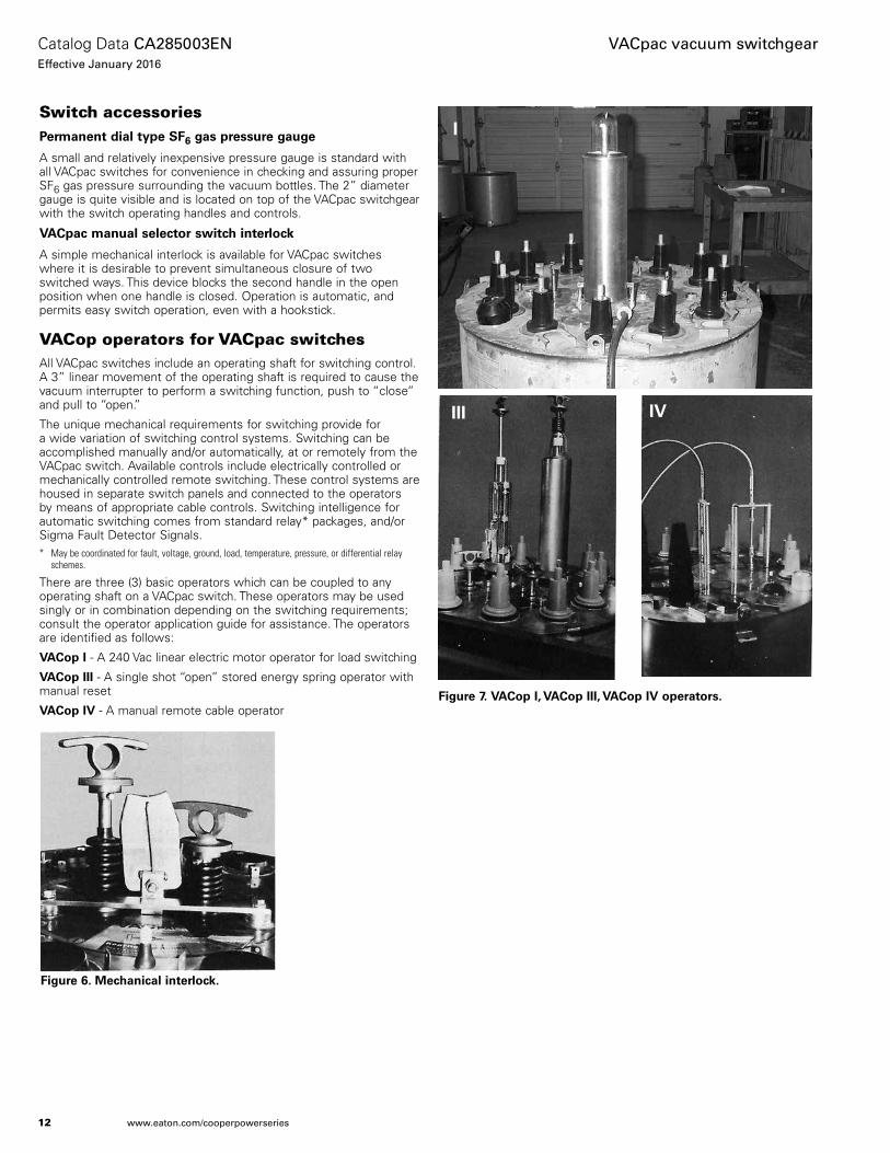
Switch accessoriesPtrmantno dial oypt SF6 gas prtssurt gaugt
A small and relatively inexpensive pressure gauge is standard with all VACpac switches for convenience in checking and assuring proper SF6 gas pressure surrounding the vacuum bottles. The 2” diameter gauge is quite visible and is located on top of the VACpac switchgear with the switch operating handles and controls.
VACpac manual stltcoNr swioch inotrlNck
A simple mechanical interlock is available for VACpac switches where it is desirable to prevent simultaneous closure of two switched ways. This device blocks the second handle in the open position when one handle is closed. Operation is automatic, and permits easy switch operation, even with a hookstick.
VACop operators for VACpac switchesAll VACpac switches include an operating shaft for switching control. A 3” linear movement of the operating shaft is required to cause the vacuum interrupter to perform a switching function, push to “close” and pull to “open.”
The unique mechanical requirements for switching provide for a wide variation of switching control systems. Switching can be accomplished manually and/or automatically, at or remotely from the VACpac switch. Available controls include electrically controlled or mechanically controlled remote switching. These control systems are housed in separate switch panels and connected to the operators by means of appropriate cable controls. Switching intelligence for automatic switching comes from standard relay* packages, and/or Sigma Fault Detector Signals.* May be coordinated for fault, voltage, ground, load, temperature, pressure, or differential relay
schemes.
There are three (3) basic operators which can be coupled to any operating shaft on a VACpac switch. These operators may be used singly or in combination depending on the switching requirements; consult the operator application guide for assistance. The operators are identified as follows:
VACNp I - A 240 Vac linear electric motor operator for load switching
VACNp III - A single shot “open” stored energy spring operator with manual reset
VACNp IV - A manual remote cable operator
Figurt 6. Mtchanical inotrlNck.
Figurt 7. VACNp I, VACNp III, VACNp IV NptraoNrs.
I
III IV
12
Catalog Data CA285003ENEffective January 2016
VACpac vacuum switchgear
www.eaton.com/cooperpowerseries

Operator control functions include automatic transfer, automatic fault interruption, a combination automatic transfer and fault isolation, and remote control switching. It is strongly suggested that the “Operator Application Guide” be consulted to select the appropriate operators.
Users should be aware of the control source voltage and current requirements. Standard packages have been developed which may assist and cover the majority of installations.
Tablt 5. OptraoNr ApplicaoiNn Guidt*
VACopVACop Combinations
Application I III IV III-IV
CNnorNl PNwtr
120 Vac • •
240 Vac •
DC Backup (12 Vdc Trip Coil) • •
AuoNmaoic Transftr •
AuoNmaoic Faulo Inotrrupoing • •
Operator Manual Reset •
Mechanical Reset •
Remote Mechanical Reset •
CNnorNl Swioching • • • •
Electrical Open/Close •
Electrical Trip • • •
Mechanical Open/Close • •
Figurt 8. AuoNmaoic oransftr oN soandby gtntraoNr.
* Automatic and electrical functions require supporting circuitry and components in a control cabinet. See pages 14 and 15 for details.
13
Catalog Data CA285003ENEffective January 2016
VACpac vacuum switchgear
www.eaton.com/cooperpowerseries

VACpac switch operationsVACNp I NptraoNr funcoiNn
VACop I operator is basically used for automatic transfer switching for critical loads. This unit operates in a minimum of five (5) cycles which includes mechanical switching and arcing times. VACop I operator may also function as an electrical remote pushbutton control close/open switch with or without the automatic transfer system included. Control voltage is 240 Vac (Line to Ground).
DtscripoiNn
VACop I operator is a direct drive linear motor connected directly to the VACpac switchgear operating shaft by means of a pinned coupling. The unit is a 6 horsepower operator requiring 240 Volt 30 A source. For automatic transfer operating 2 VACop I units are employed. One VACop I operator may be used for each switched circuit with a maximum of 4 per VACpac unit.
The removable operator housing is a stainless steel cylinder and is locked in place by means of 2 camtype clamps. A transparent dome, secured to the top of the cylindrical housing, provides a visual indication of the switch in either the closed or open positions. A ring handle on the motor shaft projects above the motor so that with the housing removed, the VACpac switchtgear can be operated manually or with a hot stick. The housing is completely sealed for submersible operations when secured to its base with the cam clamps.
Controls include modular electrical switching panels housed within a gasketed control cabinet. Pushbuttons with LEDs permit local operation and position indication of the VACpac unit. With automatic transfer controls, a “manual-off-auto” switch permits a local pushbutton switching operation which overrides the automatic controls when on “manual.” A standard 10 foot neoprene-jacketed control cable is used to connect the VACop I operator with the control cabinet (other control cable lengths much be specified). However, when considering voltage drop, source voltage to the operator motor must be held between 230 and 250 Vac to perform a switching function.
AuoNmaoic cNnorNls
Voltage sensing for automatic transfer controls is from potential transformers. Intelligence for switching is by means of standard relays housed within the control cabinet.
Figurt 9. VACNp I NptraoNr lintar tltcoric mNoNr NptraoNr.
Figurt 10. VACNp I NptraoNr dimtnsiNns.
27” Closed
30” Open
14
Catalog Data CA285003ENEffective January 2016
VACpac vacuum switchgear
www.eaton.com/cooperpowerseries
VACNp III NptraoNr funcoiNn
Complete three-phase switching of circuits even for faults is becoming more popular in order to avoid the potential hazards involving: 1) ferroresonance, 2) single-phasing of three-phase motors, 3) circulating currents in some three-phase transformers as from a single-phase fuse operation.
VACop III operator in conjunction with a special 12 kA rated VACpac fault interrupter switch will automatically clear a system fault in 5 cycles (excluding relay time). The unit will perform a single shot tripping operation which must then be manually reset. VACop III operator is available for 15, 25 and 35 kV operating systems. It is especially effective where fuses are difficult to coordinate or install. VACop III operator may also be used for remote pushbutton load interrupting applications.
DtscripoiNn
VACop III operator is a spring charged “stored energy” operator. It must be used on a VACpac unit equipped with the optional 12 kA vacuum interrupter. The operator is connected directly to the VACpac unit operating shaft by means of a pinned coupling. Fault sensing is with either overcurrent relays and CTs. A relayed trip signal is applied to the solenoid circuit which causes the spring to release and open the switch. Pulling the handle atop the VACop III operator resets the spring; a force of 65 lbs. is required to move the handle 3 inches to reset the unit. Pushing the handle atop the operator closes the switch and “arms” the tripping control circuit. A wide range of AC and DC solenoid control voltages is available. The unit is of a trip free design; it will trip when closing into a fault. The removable operator housing is a stainless steel cylinder and is locked in place by means of 2 camtype clamps. A transparent dome provides a visual indication of the switch in either the closed or open (trip) positions; a trip indicator is located under the handle. The housing is completely sealed for submersible operations when secured to its base with the cam clamps.
AuoNmaoic cNnorNls
VACop III operator controls perform an automatic trip operation in 5 cycles; this does not include relay time. The power source for automatic tripping controls may be from one of two systems:
A. Capacitor Discharge Trip Control—Energy from a charged capacitor is used to energize the solenoid and cause the VACop III operator to trip open. Energy storage time after power loss is 5+ hours; life expectancy is 10+ years.
B. Battery Trip Control—Energy from the battery is used to energize the solenoid and cause the VACop III operator to trip. Energy storage time after power loss is 5+ days; life expectancy is 2+ years.
The intelligence required to monitor and provide the trip signal is from:
A. Conventional Overcurrent Relays—Used in conjunction with “doughnut” or window type conventional current transformers. May be required for system coordination purposes.
Note:N Trip Control system above requires nominal 120 Vac for charging power which is normally supplied by the user. Specify if 120 Volt source is not available.
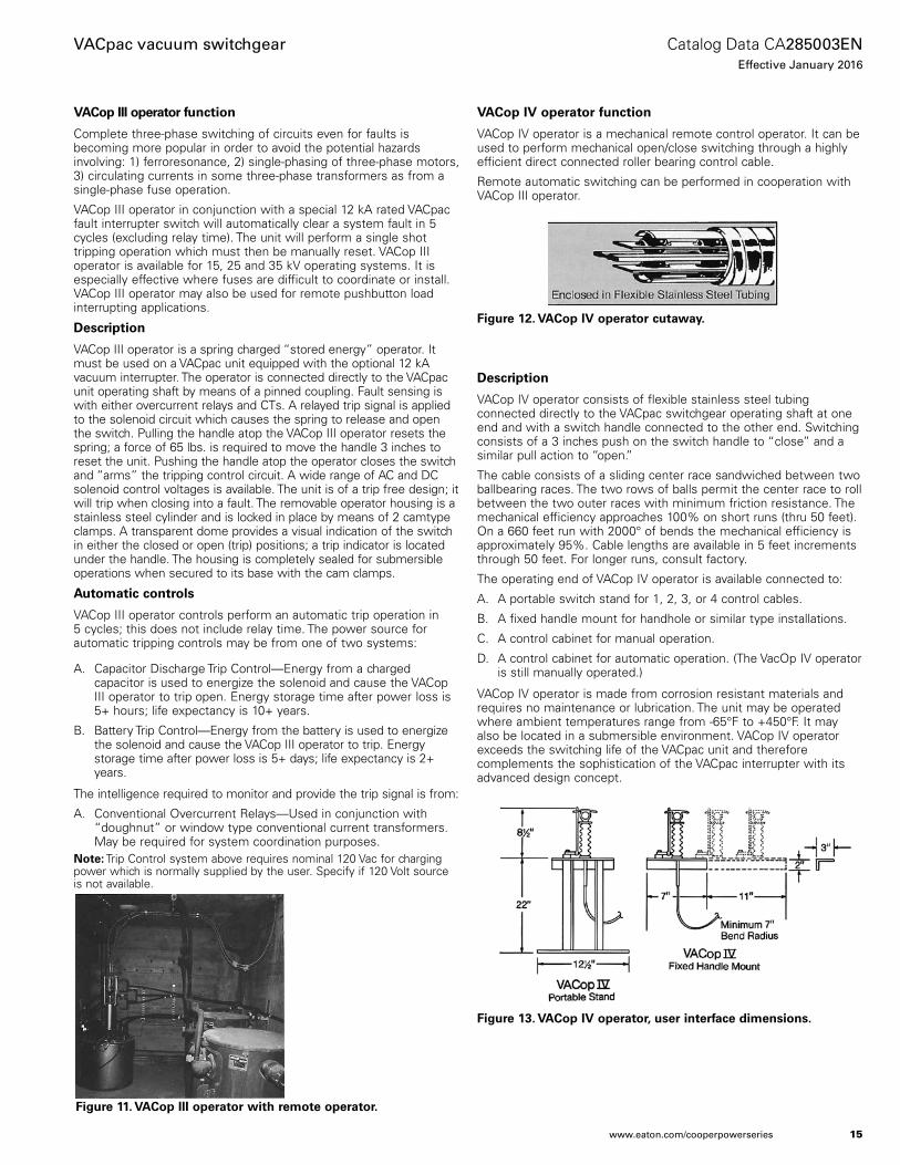
VACNp IV NptraoNr funcoiNn
VACop IV operator is a mechanical remote control operator. It can be used to perform mechanical open/close switching through a highly efficient direct connected roller bearing control cable.
Remote automatic switching can be performed in cooperation with VACop III operator.
DtscripoiNn
VACop IV operator consists of flexible stainless steel tubing connected directly to the VACpac switchgear operating shaft at one end and with a switch handle connected to the other end. Switching consists of a 3 inches push on the switch handle to “close” and a similar pull action to “open.”
The cable consists of a sliding center race sandwiched between two ballbearing races. The two rows of balls permit the center race to roll between the two outer races with minimum friction resistance. The mechanical efficiency approaches 100% on short runs (thru 50 feet). On a 660 feet run with 2000° of bends the mechanical efficiency is approximately 95%. Cable lengths are available in 5 feet increments through 50 feet. For longer runs, consult factory.
The operating end of VACop IV operator is available connected to:
A. A portable switch stand for 1, 2, 3, or 4 control cables.
B. A fixed handle mount for handhole or similar type installations.
C. A control cabinet for manual operation.
D. A control cabinet for automatic operation. (The VacOp IV operator is still manually operated.)
VACop IV operator is made from corrosion resistant materials and requires no maintenance or lubrication. The unit may be operated where ambient temperatures range from -65°F to +450°F. It may also be located in a submersible environment. VACop IV operator exceeds the switching life of the VACpac unit and therefore complements the sophistication of the VACpac interrupter with its advanced design concept.
Figurt 11. VACNp III NptraoNr wioh rtmNot NptraoNr.
Figurt 13. VACNp IV NptraoNr, ustr inotrfact dimtnsiNns.
Figurt 12. VACNp IV NptraoNr cuoaway.
15
Catalog Data CA285003ENEffective January 2016
VACpac vacuum switchgear
www.eaton.com/cooperpowerseries

ApplicaoiNns
1. Portable remote switch operator for switching underground vaults or manholes and parked in a holder when not in use.
2. Permanent control panel remote switching for vaults in buildings and underground installations.
3. For industrial or campus remote safety switching requirements.
4. Convenient handhole switching for vault or URD type switching installations.
5. Central switching for individual vaults on several levels in high rise buildings.
6. Pad-mounted enclosure switching externally operated.
7. Ground level switching for pole mounted switchgear.
8. Adjacent vault switch control in subway systems.
9. In conjunction with automatic controls for submersible switch-gear and remotely located control panels.
10. As a portable tool connection to VACpac switchgear.
Figurt 14. VACNp IV NptraoNr aooachtd oN VACpac swiochgtar.
Figurt 15. VACNp IV NptraoNr, VACpac cNnntcoiNn dimtnsiNns.
16
Catalog Data CA285003ENEffective January 2016
VACpac vacuum switchgear
www.eaton.com/cooperpowerseries

VACop IV operator application ideas
17
Catalog Data CA285003ENEffective January 2016
VACpac vacuum switchgear
www.eaton.com/cooperpowerseries

This page is intentionally left blank.
18
Catalog Data CA285003ENEffective January 2016
VACpac vacuum switchgear
www.eaton.com/cooperpowerseries

This page is intentionally left blank.
19
Catalog Data CA285003ENEffective January 2016
VACpac vacuum switchgear
www.eaton.com/cooperpowerseries
VACpac vacuum switchgear
Eaton1000 Eaton BoulevardCleveland, OH 44122United StatesEaton.com
Eaton’s Cooper Power Systems Division2300 Badger DriveWaukesha, WI 53188United StatesEaton.com/cooperpowerseries
© 2016 EatonAll Rights ReservedPrinted in USAPublication No. CA285003EN
Catalog Data CA285003ENEffective January 2016
Eaton is a registered trademark.
All other trademarks are property of their respective owners.
For Eaton's Cooper Power series product information call 1-877-277-4636 or visit: www.eaton.com/cooperpowerseries.


![m[lagf Y kk]eZdq - DELING Voltage Switchgear.pdf · VD4 series vacuum circuit breaker. V – contact, series vacuum contactor ... place from the front of the switchgear with manual](https://img.pdfslide.us/doc/110x75/5ebca888adc8bf11a53de8dd/mlagf-y-kkezdq-voltage-switchgearpdf-vd4-series-vacuum-circuit-breaker-v.jpg)