Embed Size (px)
Citation preview

A77
Available with 600 A one-piece bushings or 200 A wells on either/both terminals.
(4) Mounting holes, 55⁄88" dia. x 77⁄88" (16 x 22 mm) (4) Mounting holes, 55⁄88" dia. x 77⁄88" (16 x 22 mm)
41⁄16" (103 mm)
Open Closed
121⁄2" (318 mm)
67⁄16" (164 mm)
51⁄2" (140 mm)
137⁄16" (341 mm)
23 25⁄32" (604 mm)
815⁄16" (227 mm)
85⁄32" (207 mm)
615⁄64" (176 mm)
43°
615⁄64" (176 mm)
121⁄2" (318 mm)
51⁄2" (140 mm)
61⁄16" (154 mm)
135⁄64" (39 mm)
Open Closed
137⁄16" (341 mm)
10 5⁄32" (258 mm)
25 27⁄32" (656 mm)
43°
8 1⁄32" (204 mm) 6 51⁄64"
(173 mm)
—Underground distribution switchgearMolded vacuum switches and fault interrupters
Single-phase switches approximate weight: 30 lbs.
MVS molded vaccum switchesSpring-energy, load-switching devices that make, carry and interrupt load currents through 600 A on 5 to 38 kV distribution systems.
MVS molded vacuum switches include molded-in elbow connection interfaces and spring-energy mechanisms. Available in both single- and three-phase models, units are manually operated with a hotstick. Motor operator, SCADA and auto-transfer control options are available.
• EPDM molded rubber insulation — MVSs are fully sealed and submersible.
• Vacuum switching and vacuum — Interruption Components are maintenance-free and require no gas or oil.
• Compact and lightweight — Small footprint enables MVSs to fit in tight padmount, subsurface, vault or riser pole installations.
FISH ER P I ER CE FAU LTED CI R C U IT I N D I C ATO R S , EL A S TI M O L D U N D ER G R O U N D D IS TR I B U TI O N S W ITCH G E A R

B1 copy starts here
B2 copy starts here
B3 copy starts here
A78 E L A S TI M O LD/F I S H E R PI E RCE C A B L E ACCE SSO R IE S
19"(483 mm)
911⁄22"(241 mm)
Available with 600 A one-piece bushings or 200 A wells on either/both terminals.
1811⁄22"(483 mm)
26"(660 mm)
14"(356 mm)
21"(533 mm)
18"(470 mm)
511⁄22"(140 mm)
511⁄22"(140 mm)
Three-phase switches approximate weight: 135 lbs.
—Underground distribution switchgearMVS molded vacuum switches
—Ratings
Maximum design voltage (kV) 15.5 27 38
Frequency (Hz) 50/60 50/60 50/60
BIL impulse (kV) 95 125 150
One-minute AC withstand (kV) 35 60 70
Fifteen-minute DC withstand (kV) 53 78 103
Load interrupting & loop switching (Amp) 600 600 600
Transformer magnetizing interrupting (Amp) 21 21 21
Capacitor or cable charging interrupting (Amp) 40 40 40
Asymmetrical momentary and 3-operation fault close (Amp)
20 20 20
Symmetrical one-second rating (Amp) 12,5 12,5 12,5
Continuous current (Amp) 600 600 600
Eight-hour overload current (Amp) 900 900 900
Application information• Construction: Submersible, corrosion resistant,
fully shielded• Ambient temperature range: -40 °C to 65 °C
Certified testsMVS loadbreak switches have been designed and tested per applicable portions of IEEE, ANSI, NEMA and other industry standards, including:IEEE C37.74 standard for subsurface, vault and padmounted load-interrupting switchesIEEE 386 standard for separable connectors and bushing interfacesIEC 265 international standards for load-interrupting switchesANSI C57.12.28 standard for padmount enclosures
Molded EPDM rubber insulation and shielding
Closed position
Vacuum interrupter contact system
Cable connection bushings
Operating handle
Insulated drive rod assembly
Spring operating mechanism contained within 304 stainless steel housing Patented silicone rubber diaphragm separates line and ground potential
43°

A79
Make, carry and automatically interrupt currents through 25,000 A symmetrical on 5–38 kV distribution systems. • Vacuum interrupters, programmable, electronic,
self-powered controls and EPDM rubber insulation provide compact, lightweight and submersible overcurrent protection
• Field programmable with a wide range of time-current characteristic (TCC) curves and trip settings
• TCC curves provide predictable tripping for ease of coordination with upstream and/or downstream protective devices
• Control monitors the circuit condition – when the programmed parameters are exceeded, a signal is sent to the tripping mechanism
• Available motor operators and controls enable radial feeders or loops to be reconfigured, either manually or via SCADA
—Underground distribution switchgearMVI molded vacuum fault interrupters
MVI molded vacuum fault Interrupters include molded-in elbow connection interfaces and trip-free mechanisms. They are available in single- and three-phase models.
Application informationConstruction: submersible, corrosion resistant, fully shieldedOperating temperature range: -40 °C to 65 °C
For dimensions, see page A81.
EL A S TI M O L D U N D ER G R O U N D D IS TR I B U TI O N S W ITCH G E A R

B1 copy starts here
B2 copy starts here
B3 copy starts here
A80 E L A S TI M O LD/F I S H E R PI E RCE C A B L E ACCE SSO R IE S
—Underground distribution switchgearMVI molded vacuum fault interrupters
Spring-operated mechanism with tripping
Cable connection bushings
Vacuum fault interrupter contact system
Molded EPDM rubber insulation and shielding
Positive contact position
Operating handle
Patented silicone rubber diaphragm separates line
and ground potential
Insulated drive rod assembly
Control module (1-phase) Sensing module (3-phase)
MVI molded vacuum fault interrupters have been designed and tested per applicable portions of IEEE, ANSI, NEMA and other industry standards, including:
ANSI C37.60 Standard for fault interrupters
IEEE 386 Standard for separable connectors and bushing interfaces
ANSI C57.12.28 Standard for padmounted enclosures
Voltage class (kV) 15 15 15 27 35 35
Maximum design voltage (kV) 17 17 15.5 29 38 38
Frequency (Hz) 50/60 50/60 50/60 50/60 50/60 50/60
BIL impulse (kV) 95 95 95 125 150 150
One-minute AC withstand (kV) 35 35 35 40 50 50
15-minute DC withstand (kV) 53 53 53 78 103 103
Load interrupting and loop switching (Amp) 630 630 630 630 630 630
Capacitor or cable charging interrupting (Amp) 10 10 10 25 40 40
Line charging (Amp) 2 2 2 5 5 5
Asymmetrical momentary and 3-operation fault close (Amp)
20,000 25,600 32,000 20,000 20,000 40,000
Symmetrical one-second rating (Amp) 12,500 16,000 20,000 12,500 12,500 25,000
Continuous current (Amp) 630 630 630 630 630 630
Eight-hour overload current (Amp) 900 900 900 900 900 900
Current sensor ratio 1,000:1 1,000:1 1,000:1 1,000:1 1,000:1 1,000:1
Mechanism Spring operating
Spring operating
Spring operating
Spring operating
Spring operating
Mag actuator
—Certified tests
—MVI ratings
A81EL A S TI M O L D U N D ER G R O U N D D IS TR I B U TI O N S W ITCH G E A R
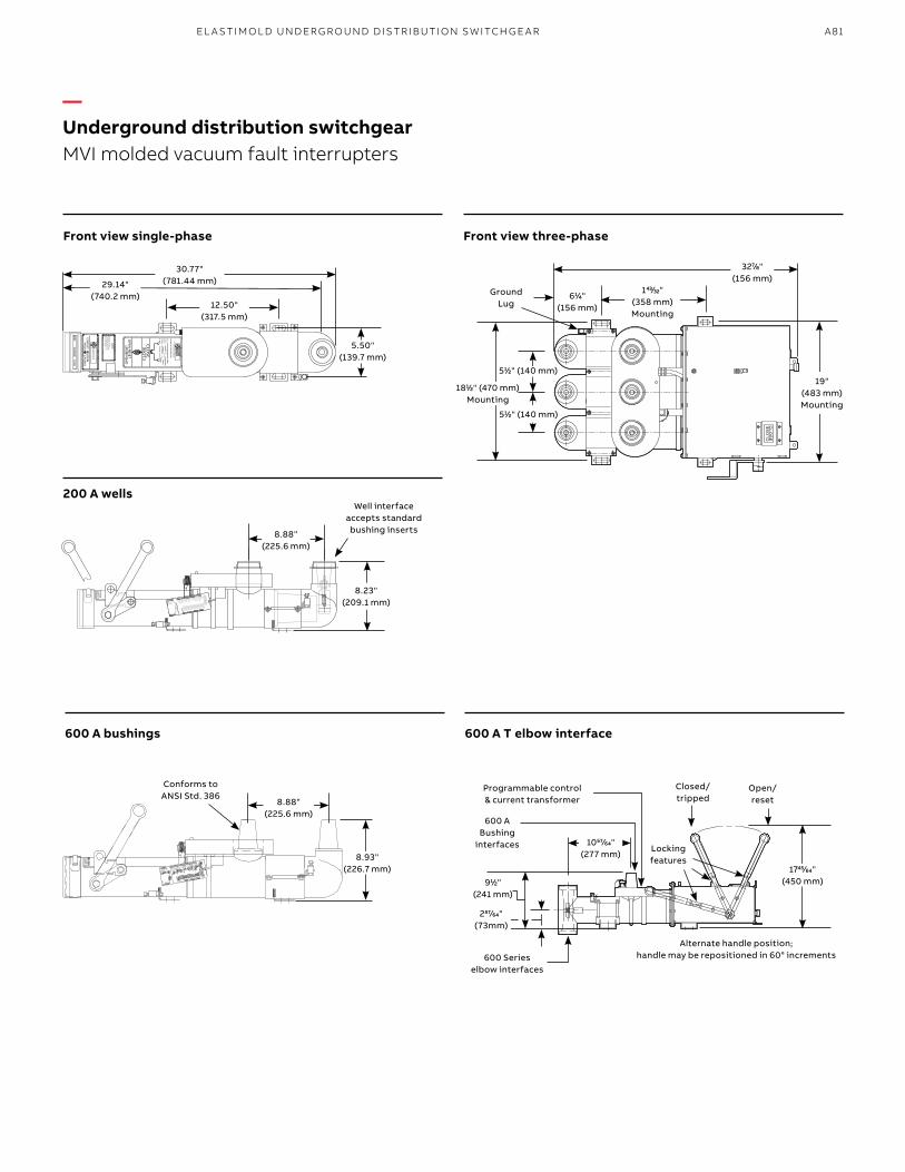
—Underground distribution switchgearMVI molded vacuum fault interrupters
8.88" (225.6 mm)
Well interface accepts standard bushing inserts
8.23"(209.1 mm)
Conforms to ANSI Std. 386
611⁄44" (156 mm)
Ground Lug
Open/ reset
Closed/ tripped
600 A Bushing
interfaces
911⁄22" (241 mm)
5.50" (139.7 mm)
30.77"(781.44 mm)29.14"
(740.2 mm)12.50"
(317.5 mm)
8.88" (225.6 mm)
8.93" (226.7 mm)
19"(483 mm) Mounting
3277⁄88" (156 mm)
1811⁄22" (470 mm) Mounting
14343⁄3232" (358 mm) Mounting
174545⁄6464" (450 mm)
105757⁄6464" (277 mm)
511⁄22" (140 mm)
Locking features
Alternate handle position;handle may be repositioned in 60° increments
511⁄22" (140 mm)
600 Series elbow interfaces
25757⁄6464" (73mm)
Programmable control & current transformer
600 A T elbow interface600 A bushings
Front view three-phaseFront view single-phase
200 A wells

B1 copy starts here
B2 copy starts here
B3 copy starts here
A82 E L A S TI M O LD/F I S H E R PI E RCE C A B L E ACCE SSO R IE S
• Self-powered electronic control packages – No batteries or external power are required
• Controls send a signal to the vacuum interrupters to trip open and interrupt the fault when an overcurrent condition is detected
• Field-selectable fuse or relay curves and trip settings – one device for many protection schemes
Molded vacuum interrupters are provided with self-powered electronic control packages requiring no batteries or external power. Depending on the application, six electronic control options are available for the MVI – See below and on following page.
—01 Internal control—02 External control
—01
—02
—Molded vacuum interrupter and switchgear controlsChoose among various electronic control options to interrupt faults
Internal controlThis control is integral to the unit (no separate control box). It is accessible via a computer connection to view or modify settings. This control is used on ganged three-phase or single- phase MVI interrupters. Phase and ground trip, as well as inrush restraint, are available. The E-Set software enables the user to connect to the internal control, either in the shop or in the field, to program or change settings. An MVI-STP-USB programming connector is required to connect between the PC and the MVI. With a computer connected to the MVI control, the user can view real-time currents, the number of overcurrent protection operations, current magnitude of the last trip and the phase/ground fault targets. This is the standard control option.Note: E-Set can be downloaded from www.elastimoldswitchgear.com.
External control with selectable single-/ three-phase trip function (style 80)This control is mounted externally to the mechanism of the interrupter and provides the ability to select between a single-phase trip and a three-phase trip. The 80 can be used with one three-phase interrupter or the 380 control with three single-phase interrupters. For three-phase applications, the ground trip function can be blocked from the front panel. Manual trip and reset target buttons are also located on the front panel. This control uses the E-Set software, which enables programming via a computer using the MVI-STP-USB adapter. E-Set features custom TCC curves and provides access to the last fault event information, as well as real-time current per phase.

A83EL A S TI M O L D U N D ER G R O U N D D IS TR I B U TI O N S W ITCH G E A R
Curve no. Curve
reference no. Curve type
Relay curves (minimum trip 30–600 A)
01 MVI-TCC-01 E slow
02 MVI-TCC-02 E standard
03 MVI-TCC-03 Oil fuse cutout
04 MVI-TCC-04 K
05 MVI-TCC-05 Kearney QA
06 MVI-TCC-06 Cooper EF
07 MVI-TCC-07 Cooper NX-C
08 MVI-TCC-08 CO-11-1
09 MVI-TCC-09 CO-11-2
10 MVI-TCC-10 T
11 MVI-TCC-11 CO-9-1
12 MVI-TCC-12 CO-9-2
13 MVI-TCC-13 Cooper 280ARX
14 MVI-TCC-14 F
16 MVI-TCC-16 Kearney KS
17 MVI-TCC-17 GE relay
18–23 MVI-TCC-18–23 CO-8-1–CO-8-6
24–27 MVI-TCC-24–27 CO-9-3–CO-9-6
28–31 MVI-TCC-28–31 CO-11-3–CO-11-6
Fuse curves (minimum trip 10–200 A)
54 MVI-TCC-54 E slow
55 MVI-TCC-55 E standard
56 MVI-TCC-56 Oil fuse cutout
57 MVI-TCC-57 K
58 MVI-TCC-58 Kearney QA
59 MVI-TCC-59 Cooper NX-C
60 MVI-TCC-60 T
Smart grid readyWorks with the industry-leading protection and automation controls• SEL automation controls from Schweitzer
Engineering Laboratories
—Molded vacuum interrupter and switchgear controls
—01 SEL-751AFeeder protection—02 SEL-451 Automation and auto-transfer controls (standard and fast transfer options)
—01
—02
—Elastimold 80 control time current curves (TCCs)

B1 copy starts here
B2 copy starts here
B3 copy starts here
A84 E L A S TI M O LD/F I S H E R PI E RCE C A B L E ACCE SSO R IE S
Suffix Description
80 External 80 control with selectable single-/three-phase trip function (to be used on ganged three-phase MVI mechanism)
380 External 80 control with selectable single-/three-phase trip function (to be used on three single-phase mechanisms)
MO120A 120 V AC motor controller for MVS3 or MVI3 units (includes standard 30-ft. cable)
MO12D 12–24 V DC motor controller for MVS3 or MVI3 units (includes standard 30-ft. cable)
PS Parking stand for MVS or MVI (between bushings for single- or three-phase units)
MPS Parking stand for MVS3, MVI3 or RMVI3 on mechanism cover
PS6 Double parking stand for MVS3, MVI3 or RMVI3 (between bushings and on mechanism cover)
BT Bail tab plate installed for three-phase units only
P Customer settings to be programmed at the factory
NOTE: Leave suffix blank for internal (self-contained) control.
The following diagram shows how to construct a catalog number for molded vacuum switches and interrupters.
—1) For riser pole option, specify where to locate air bushings.2) Wind farm option is only for 38 kV, 600 A interrupter.3) Air bushings can only be specified for 600 A.
M V 2 1 Suffix
Indicates field that must be filled in to complete order.
—Ordering informationElastimold MVS and MVI units
Example: The catalog number for a molded vacuum interrupter on a three-phase, 27 kV system, with 600 A terminal and parking stands between bushings is MVI3212766PS.
Switch typeRiser pole1 R Network N Wind farm2 W Subsurface Blank
Interface600 A T body E End interface R rotated 180° Air bushings AB (for riser pole)3
Main interface200 A bushing well 2 600 A bushing 6
Interface600 A T body E End interface R rotated 180° Air bushings AB (for riser pole)3
Voltage class (Sym/asym kA)15.0 kV 15 (12.5/20) 15.0 kV (20/32) 15A interrupter only15.0 kV (16/25.6) 15B interrupter only 27.0 kV 27 (12.5/20) 38.0 kV 38 (12.5/20) 38.0 kV (25/40) 38B interrupter only
DeviceSwitch S Interrupter I
PhasesSingle-phase 1 Three-phase 3
End interface200 A 2 bushing well 600 A 6 bushing
—Controls and accessories

A85EL A S TI M O L D U N D ER G R O U N D D IS TR I B U TI O N S W ITCH G E A R
—Accessories (order separately)
Cat. no. Description
MVI-STP-USB Adapter for connection between MVI units with internal control and a computer for programming/viewing settings
MV1PMB Pole-mounting bracket for 1-phase units only
MV3PMB Pole-mounting bracket for 3-phase units only
MV3HPMB Horizontal pole-mounting bracket for 3-phase units only
MV13PMB Pole-mounting bracket for three 1-phase units only
35AL-11 Connector bare wire type 3⁄4"–16 rod for riser pole units; qty. Of 1 needed per phase
35AL-12 Connector 2-hole spade type 3⁄4"–16 rod for riser pole units; qty. Of 1 needed per phase
Notes: Weights and dimensions are approximate.X = 6 for 600 A or 2 for 200 A or 6E for 600 A T interface.Y = 10, 20, 30, 80 for different electronic controls.Leave blank for internal (self-contained) control.Accessories should be added as suffix to the main catalog number unless otherwise noted.Other configurations are available. Please consult your local representative on configurations not shown here.The 3-phase vacuum interrupters are motor-ready.
—Elastimold MVI molded vacuum interrupters***
Cat. no. DescriptionWidth in.
(mm)Height in.
(mm)Depth in.
(mm)Weight lb.
(kg) Diagram
Riser pole (three-phase installations only)
RMVI3-21-15-6ABX-YY 15 kV 2-way 3-phase interrupter with air bushings on top terminals 30 (762) 45 (1,143) 25 (635) 150 (68)
RMVI3-21-27-6ABX-YY 25 kV 2-way 3-phase interrupter with air bushings on top terminals 30 (762) 45 (1,143) 25 (635) 150 (68)
RMVI3-21-38-6ABX-YY 38 kV 2-way 3-phase interrupter with air bushings on top terminals 30 (762) 45 (1,143) 25 (635) 150 (68)
RMVI1-21-15-6ABX-3YY 15 kV 2-way 3-phase interrupter with air bushings on top terminals, 1-phase trip selectable
30 (762) 45 (1,143) 25 (635) 150 (68)
RMVI1-21-27-6ABX-3YY 27 kV 2-way 3-phase interrupter with air bushings on top terminals, 1-phase trip selectable
30 (762) 45 (1,143) 25 (635) 150 (68)
RMVI1-21-38-6ABX-3YY 38 kV 2-way 3-phase interrupter with air bushings on top terminals, 1-phase trip selectable
30 (762) 45 (1,143) 25 (635) 150 (68)
Subsurface single-phase vacuum switches
MVI1-21-15-XX 15 kV 2-way 1-phase interrupter 6 (152) 31 (787) 9 (229) 45 (20)
MVI1-21-15-6EX 15 kV 2-way 1-phase interrupter, elbow interface 6 (152) 31 (787) 11 (279) 45 (20)
MVI1-21-27-XX 27 kV 2-way 1-phase interrupter 6 (152) 31 (787) 9 (229) 45 (20)
MVI1-21-27-6EX 27 kV 2-way 1-phase interrupter, elbow interface 6 (152) 31 (787) 11 (279) 45 (20)
MVI1-21-38-XX 38 kV 2-way 1-phase interrupter 6 (152) 31 (787) 9 (229) 45 (20)
MVI1-21-38-6EX 38 kV 2-way 1-phase interrupter, elbow interface 6 (152) 31 (787) 11 (279) 45 (20)
Subsurface three-phase vacuum switches
MVI1-21-15-XX-3YY 15 kV 2-way 3-phase interrupter, 1-phase trip selectable ext. control
20 (508) 31 (787) 9 (229) 145 (66)
MVI1-21-27-XX-3YY 27 kV 2-way 3-phase interrupter, 1-phase trip selectable ext. control
20 (508) 31 (787) 9 (229) 145 (66)
MVI1-21-38-XX-3YY 38 kV 2-way 3-phase interrupter, 1-phase trip selectable ext. control
20 (508) 31 (787) 9 (229) 145 (66)
MVI3-21-15-XX-YY 15 kV 2-way 3-phase interrupter 20 (508) 33 (838) 10 (254) 145 (66)
MVI3-21-27-XX-YY 27 kV 2-way 3-phase interrupter 20 (508) 33 (838) 10 (254) 145 (66)
MVI3-21-38-XX-YY 38 kV 2-way 3-phase interrupter 20 (508) 33 (838) 10 (254) 145 (66)
*** Air bushings on top terminal.
—Underground distribution switchgearMolded vacuum switchs and fault interrupters

B1 copy starts here
B2 copy starts here
B3 copy starts here
A86 E L A S TI M O LD/F I S H E R PI E RCE C A B L E ACCE SSO R IE S
Multi-way unit constructionMulti-way vault and padmount units are built using MVS and MVI modules as required by the application. These are mounted onto the ES multi-way common bus system and assembled on a free-standing, floor-mounted frame. At this stage, the product is ready to be used in vault installations.
For padmount installations, a double-sided, drop-over, painted, mild steel enclosure is provided. Munsell Green 7GY 3.29/1.5 is the standard enclosure color. Other colors are available upon request. Painted stainless steel or fiberglass enclosures are available as options.
Top lifts up for easeof operation
200 A wells available; 600 A bushings (shown)
Internal electronic control and current-sensing device (3-phase MVI and external controls also available)
Ground rod
Parking stand
Mild or stainless steel enclosures available
Internal electronic control and current-
sensing device (3-phase MVI and external controls
also available)
—Underground distribution switchgearElastimold multi-way switchgear and transfer packages
—01 Subsurface-style unit—02 Vault-style unit—03 Padmount unit (load side)
—01
—02
—03
MVI mechanism on 1-phase protection tap (3-phase also available)

A87EL A S TI M O L D U N D ER G R O U N D D IS TR I B U TI O N S W ITCH G E A R
The following diagram shows how to construct a catalog number for multi-way switchgear or transfer packages.
Example: Multi-way switchgearMD3142T2P62XIXXAE000: Multi-way, double-sided padmount, 3-phase, 15.0 kV, 95 kV BIL, 12.5 kA interrupting capability, 4-ways, 2 source ways, source component: three-phase molded vacuum switches (MVS3), 2 load ways, load component: three-phase molded vacuum interrupter (MVI3), 600 A bushing interfaces (source), 200 A bushing well interfaces (load), source control: none, load control: Elastimold MVI internal control, PT: PT not required, enclosure: mild steel, Munsell green 7GY 3.29/1.5 and flat ground bar, English labels and instructions.
—Underground distribution switchgearElastimold multi-way switchgear and transfer packages
Example: Auto transfer switchgear with SEL control packageTD3242H2P62GHFXAE000: Automatic transfer, double-sided padmount, 3-phase, 27.0 kV, 125 kV BIL, 12.5 kA interrupting capability, 4-ways, 2 source ways, source component: three-phase molded vacuum switches (MVS3) with 12–24 V DC motor and voltage sensors, 2 load ways, load component: three-phase molded vacuum interrupter (MVI3), 600 A bushing interfaces (source), 200 A bushing well interfaces (load), source control: sel 451-5 relay, load control: SEL 751A relay, PT: two (2) 27 kV PT (13200–14400 V AC (WYE), enclosure: mild steel, Munsell green 7GY 3.29/1.5 and flat ground bar, English labels and instructions.
Indicates field that must be filled in to complete order.
Switch typeMulti-way M switchgearStandard T auto transfer – motorsFast auto F transfer – actuatorsAuto loop L restoration
Mounting styleDouble-sided D padmountSingle-sided P padmountSubsurface V (dry vault)Subsurface S (submersible external control)
Voltage class15.0 kV 127.0 kV 238.0 kV 3Subsurface S (submersible external control)
Number of ways2-way 23-way 34-way 45-way 56-way 6
Number of source ways1-way 12-way 23-way 34-way 45-way 56-way 6
Number of load ways (no. of ways – no. source ways)None X1-way 12-way 23-way 34-way 45-way 5
Source ways interface200 A 2 bushing well source600 A 6 bushing well source
Source way componentsSolid tap/direct bus connection (600 A or 200 A) B3-phase MVS switch T3-phase MVS switch with motor U3-phase MVS switch with motor & voltage sensors H3-phase MVS switch with magnetic actuator M & voltage sensors (fast transfer units only)3-phase MVI fault interrupter P3-phase MVI fault interrupter with motor R3-phase MVI fault interrupter with motor & voltage sensors G
Load way components None XSolid tap/direct bus connection B (600 A or 200 A)1-phase MVS switch S3-phase MVS switch T3-phase MVS switch with motor U3-phase MVS switch with motor H & voltage sensors1-phase MVI fault interrupter J3-phase MVI fault interrupter P3-phase MVI fault interrupter R with motor3-phase MVI fault interrupter G with motor & voltage sensors
Phases3-phase 3

B1 copy starts here
B2 copy starts here
B3 copy starts here
A88 E L A S TI M O LD/F I S H E R PI E RCE C A B L E ACCE SSO R IE S
Example: Auto transfer switchgear with Elastimold control packageTD3242H2P62AFFXAE000: Automatic transfer, double-sided padmount, 3-phase, 27.0 kV, 125 kV BIL, 12.5 kA interrupting capability, 4-ways, 2 source ways, source component: three-phase molded vacuum switches (MVS3) with 12–24 V DC motor and voltage sensors, 2 load ways, load component: three-phase molded vacuum interrupter (MVI3), 600 A bushing interfaces (source), 200 A bushing well interfaces (load), source control: Elastimold automatic transfer control, load control: Elastimold 80 control: TCCs select through E-set software, PT: two (2) 27 kV PT (13200–14400 V AC (WYE), enclosure: mild steel, Munsell green 7GY 3.29/1.5 and flat ground bar, English labels and instructions.
Online switchgear configuratorThe ABB online switchgear configurator makes it easy to order Elastimold switchgear by walking you step by step through configuration. See pages A89–A90 for details.
—Underground distribution switchgearElastimold multi-way switchgear and transfer packages
Load ways interfaceNone X200 A 2 bushing well load600 A 6 bushing load
Source controlsNone XInternal control IElastimold M motor controlElastimold 80 F control: TCCs select through E-Set softwareElastimold auto A transfer control (ATS control)SEL 751A relay HSEL 451 relay G
Load controlNone XInternal control IElastimold motor M controlElastimold 80 control: F TCC's select through E-Set softwareElastimold SCADA 80 S control: TCCs select through E-Set software, SCADA readySEL 751A relay H
Labels and instructions languageEnglish labels E and instructionsSpanish labels S and instructions
Switchgear alphanumeric characters 0
Cam-Op and integral position indicatorNone XCam-Ops load ways A (600 A ways)Cam-Ops source ways B (600 A ways)Cam-Ops all ways C (on all 600 A ways)Position indicators D load ways (m&m)Position indicators E source ways (m&m)Position indicators all F ways (m&m)
Solid dielectric PT to power controlsNone XOne (1) 15 kV PT (7000–7620 V AC (Wye) AOne (1) 27 kV PT (13200–14400 V AC (Wye) BOne (1) 38 kV PT (19000–20750 V AC (Wye) COne (1) 38 kV PT (34500–38000 V AC (Delta) DTwo (2) 15 kV PT (7000–7620 V AC (Wye) ETwo (2) 27 kV PT (13200–14400 V AC (Wye) F Two (2) 38 kV PT (19000–20750 V AC (Wye) G
Enclosure material, enclosure color and ground barNone (subsuface) XMild steel, Munsell green 7GY 3.29/1.5 & flat ground bar AMild steel, Munsell Canadian green 9GY 1.5/2.6 & flat ground bar BMild steel, Munsell green 7GY 3.29/1.5 & round ground bar CMild steel, Munsell Canadian green 9GY 1.5/2.6 & round ground bar DStainless steel, Munsell green 7GY 3.29/1.5 & flat ground bar EStainless steel, Munsell Canadian green 9GY 1.5/2.6 & flat ground bar FStainless steel, Munsell green 7GY 3.29/1.5 & round ground bar GStainless steel, Munsell Canadian green 9GY 1.5/2.6 & round ground bar H
Indicates field that must be filled in to complete order.

A89EL A S TI M O L D U N D ER G R O U N D D IS TR I B U TI O N S W ITCH G E A R
Single-side padmount ESP313-BJB-626 Double-side padmount ESD3X4-IIPP-6622-S
Subsurface ESS3X2-TT-66
MSV3 Switch
Stainless steel bottom rails
511⁄22"(140mm)
84"(2,134mm)
42"(1,067mm)
54"(1,372mm)
54"(1,372mm)
3311⁄88"(841mm)
19"(483mm)
3533⁄88"(899mm)
48"(1,219mm)
—Elastimold switching and sectionalizing switchgear
Cat. no. Description Width in. (mm) Height in. (mm) Depth in. (mm) Weight lb. (kg) Diagram
Vault
ESV313-TTT-XXX 15 kV 3-way 3-phase switch 48 (1,219) 36 (914) 22 (559) 750 (340)
ESV323-TTT-XXX 27 kV 3-way 3-phase switch 48 (1,219) 36 (914) 22 (559) 750 (340)
ESV333-TTT-XXX 38 kV 3-way 3-phase switch 48 (1,219) 36 (914) 22 (559) 750 (340)
ESV314-TTTT-XXXX 15 kV 4-way 3-phase switch 48 (1,219) 36 (914) 22 (559) 880 (399)
ESV324-TTTT-XXXX 27 kV 4-way 3-phase switch 48 (1,219) 36 (914) 22 (559) 880 (399)
ESV334-TTTT-XXXX 38 kV 4-way 3-phase switch 48 (1,219) 36 (914) 22 (559) 880 (399)
Padmount
PMVS1-21-15-XX 15 kV 2-way 3-phase switch 36 (914) 30 (762) 30 (762) 310 (141)
PMVS1-21-27-XX 27 kV 2-way 3-phase switch 36 (914) 30 (762) 30 (762) 310 (141)
PMVS1-21-38-XX 38 kV 2-way 3-phase switch 36 (914) 30 (762) 30 (762) 310 (141)
ESD312-T-XX 15 kV 2-way 3-phase switch 36 (914) 48 (1,219) 42 (1,067) 680 (308)
ESD322-T-XX 27 kV 2-way 3-phase switch 36 (914) 48 (1,219) 42 (1,067) 680 (308)
ESD332-T-XX 38 kV 2-way 3-phase switch 36 (914) 48 (1,219) 42 (1,067) 680 (308)
ESD313-TTT-XXX 15 kV 3-way 3-phase switch 54 (1,317) 48 (1,219) 54 (1,317) 1,250 (567)
ESD323-TTT-XXX 27 kV 3-way 3-phase switch 54 (1,317) 48 (1,219) 54 (1,317) 1,250 (567)
ESD333-TTT-XXX 38 kV 3-way 3-phase switch 54 (1,317) 48 (1,219) 54 (1,317) 1,250 (567)
ESD314-TTTT-XXXX 15 kV 4-way 3-phase switch 54 (1,317) 48 (1,219) 54 (1,317) 1,380 (626)
ESD324-TTTT-XXXX 27 kV 4-way 3-phase switch 54 (1,317) 48 (1,219) 54 (1,317) 1,380 (626)
ESD334-TTTT-XXXX 38 kV 4-way 3-phase switch 54 (1,317) 48 (1,219) 54 (1,317) 1,380 (626)
Note: X = 6 for 600 A or 2 for 200 A. Other configurations are available. Consult your local representative for configurations not shown here.
Vault ESV3X4-TTTT-2222
—Underground distribution switchgearElastimold multi-way switchgear and transfer packages
Diagrams

B1 copy starts here
B2 copy starts here
B3 copy starts here
A90 E L A S TI M O LD/F I S H E R PI E RCE C A B L E ACCE SSO R IE S
—Elastimold overcurrent protection switchgear
Cat. no. DescriptionWidth in.
(mm)Height in.
(mm)Depth in.
(mm)Weight lb. (kg) Diagram
Vault
ESV313-TPP-XXX 15 kV 3-way 3-phase (1) source switch, (2) vacuum interrupter taps 40 (1,016) 48 (1,219) 22 (559) 660 (299)
ESV323-TPP-XXX 27 kV 3-way 3-phase (1) source switch, (2) vacuum interrupter taps 40 (1,016) 48 (1,219) 22 (559) 660 (299)
ESV313-TTP-XXX 15 kV 3-way 3-phase (2) source switches, (1) vacuum interrupter tap 40 (1,016) 48 (1,219) 22 (559) 660 (299)
ESV323-TTP-XXX 27 kV 3-way 3-phase (2) source switches, (1) vacuum interrupter tap 40 (1,016) 48 (1,219) 22 (559) 660 (299)
ESV314-TPPP-XXXX 15 kV 4-way 3-phase (1) source switch, (3) vacuum interrupter taps 40 (1,016) 48 (1,219) 22 (559) 880 (399)
ESV324-TPPP-XXXX 27 kV 4-way 3-phase (1) source switch, (3) vacuum interrupter taps 40 (1,016) 48 (1,219) 22 (559) 880 (399)
ESV314-TTPP-XXXX 15 kV 4-way 3-phase (2) source switches, (2) vacuum interrupter taps 40 (1,016) 48 (1,219) 22 (559) 880 (399)
ESV324-TTPP-XXXX 27 kV 4-way 3-phase (2) source switches, (2) vacuum interrupter taps 40 (1,016) 48 (1,219) 22 (559) 880 (399)
ESV314-TTTP-XXXX 15 kV 4-way 3-phase (3) source switches, (1) vacuum interrupter tap 40 (1,016) 48 (1,219) 22 (559) 880 (399)
ESV324-TTTP-XXXX 27 kV 4-way 3-phase (3) source switches, (1) vacuum interrupter tap 40 (1,016) 48 (1,219) 22 (559) 880 (399)
Padmount
PMVI1-21-15-XX 15 kV 2-way 1-phase interrupter 36 (914) 30 (762) 30 (762) 310 (141)
PMVI1-21-27-XX 27 kV 2-way 1-phase interrupter 36 (914) 30 (762) 30 (762) 310 (141)
PMVI1-21-38-XX 38 kV 2-way 1-phase interrupter 36 (914) 30 (762) 30 (762) 310 (141)
PMVI1-21-15-XX-3YY 15 kV 2-way 3-phase interrupter 1-phase trip selectable ext. control 48 (1,219) 42 (1,067) 30 (762) 680 (308)
PMVI1-21-27-XX-3YY 27 kV 2-way 3-phase interrupter 1-phase trip selectable ext. control 48 (1,219) 42 (1,067) 30 (762) 680 (308)
PMVI1-21-38-XX-3YY 38 kV 2-way 3-phase interrupter 1-phase trip selectable ext. control 48 (1,219) 42 (1,067) 30 (762) 680 (308)
ESD312-P-XX 15 kV 2-way 3-phase (1) vacuum interrupter tap 36 (914) 48 (1,219) 42 (1,067) 680 (308)
ESD322-P-XX 27 kV 2-way 3-phase (1) vacuum interrupter tap 36 (914) 48 (1,219) 42 (1,067) 680 (308)
ESD332-P-XX 38 kV 2-way 3-phase (1) vacuum interrupter tap 36 (914) 48 (1,219) 42 (1,067) 680 (308)
ESD313-TPP-XXX 15 kV 3-way 3-phase (1) source switch, (2) vacuum interrupter taps 54 (1,372) 48 (1,219) 54 (1,372) 1,160 (526)
ESD323-TPP-XXX 27 kV 3-way 3-phase (1) source switch, (2) vacuum interrupter taps 54 (1,372) 48 (1,219) 54 (1,372) 1,160 (526)
ESD333-TPP-XXX 38 kV 3-way 3-phase (1) source switch, (2) vacuum interrupter taps 72 (1,829) 54 (1,372) 72 (1,829) 1,500 (680)
ESD313-TTP-XXX 15 kV 3-way 3-phase (2) source switches, (1) vacuum interrupter tap 54 (1,372) 48 (1,219) 54 (1,372) 1,160 (526)
ESD323-TTP-XXX 27 kV 3-way 3-phase (2) source switches, (1) vacuum interrupter tap 54 (1,372) 48 (1,219) 54 (1,372) 1,160 (526)
ESD333-TTP-XXX 38 kV 3-way 3-phase (2) source switches, (1) vacuum interrupter tap 72 (1,829) 54 (1,372) 72 (1,829) 1,500 (680)
ESD314-TPPP-XXXX 15 kV 4-way 3-phase (1) source switch, (3) vacuum interrupter taps 54 (1,372) 48 (1,219) 54 (1,372) 1,380 (626)
ESD324-TPPP-XXXX 27 kV 4-way 3-phase (1) source switch, (3) vacuum interrupter taps 54 (1,372) 48 (1,219) 54 (1,372) 1,380 (626)
ESD334-TPPP-XXXX 38 kV 4-way 3-phase (1) source switch, (3) vacuum interrupter taps 72 (1,829) 54 (1,372) 72 (1,829) 1,500 (680)
ESD314-TTPP-XXXX 15 kV 4-way 3-phase (2) source switches, (2) vacuum interrupter taps 54 (1,372) 48 (1,219) 54 (1,372) 1,380 (626)
ESD324-TTPP-XXXX 27 kV 4-way 3-phase (2) source switches, (2) vacuum interrupter taps 54 (1,372) 48 (1,219) 54 (1,372) 1,380 (626)
ESD334-TTPP-XXXX 38 kV 4-way 3-phase (2) source switches, (2) vacuum interrupter taps 72 (1,829) 54 (1,372) 72 (1,829) 1,500 (680)
ESD314-TTTP-XXXX 15 kV 4-way 3-phase (3) source switches, (1) vacuum interrupter tap 54 (1,372) 48 (1,219) 54 (1,372) 1,380 (626)
ESD324-TTTP-XXXX 27 kV 4-way 3-phase (3) source switches, (1) vacuum interrupter tap 54 (1,372) 48 (1,219) 54 (1,372) 1,380 (626)
ESD334-TTTP-XXXX 38 kV 4-way 3-phase (3) source switches, (1) vacuum interrupter tap 72 (1,829) 54 (1,372) 72 (1,829) 1,500 (680)
Note: X = 6 for 600 A or 2 for 200 A. YY = 10, 20, 30, 80 for different electronic controls. Consult your local representative on 38 kV multi-way configurations.
—Underground distribution switchgearElastimold multi-way switchgear and transfer packages