Embed Size (px)
Citation preview
CA15 Scope Meter Instruction Manual
Adobe recommends using Adobe Reader or Adobe Acrobat version X or later to work with documents contained within a PDF Package.
page.01
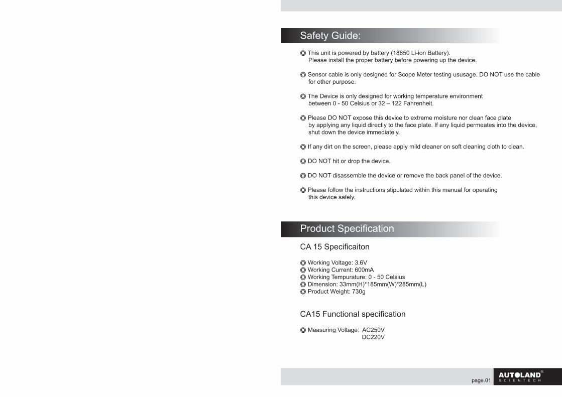
Safety Guide:◎ This unit is powered by battery (18650 Li-ion Battery). Please install the proper battery before powering up the device.
◎ Sensor cable is only designed for Scope Meter testing ususage. DO NOT use the cable for other purpose.
◎ The Device is only designed for working temperature environment between 0 - 50 Celsius or 32 – 122 Fahrenheit.
◎ Please DO NOT expose this device to extreme moisture nor clean face plate by applying any liquid directly to the face plate. If any liquid permeates into the device, shut down the device immediately.
◎ If any dirt on the screen, please apply mild cleaner on soft cleaning cloth to clean.
◎ DO NOT hit or drop the device.
◎ DO NOT disassemble the device or remove the back panel of the device.
◎ Please follow the instructions stipulated within this manual for operating this device safely.
Product Specification
CA 15 Specificaiton
◎ Working Voltage: 3.6V◎ Working Current: 600mA◎ Working Tempurature: 0 - 50 Celsius ◎ Dimension: 33mm(H)*185mm(W)*285mm(L)◎ Product Weight: 730g
CA15 Functional specification
◎ Measuring Voltage: AC250V DC220V
page. page.02 03
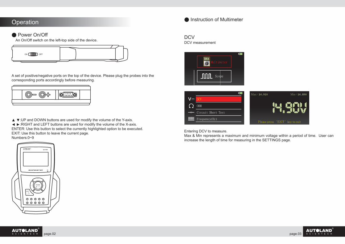
● Instruction of Multimeter
DCVDCV measurement
Entering DCV to measure. Max & Min represents a maximum and minimum voltage within a period of time. User can increase the length of time for measuring in the SETTINGS page.
Operation
● Power On/Off An On/Off switch on the left-top side of the device.
A set of positive/negative ports on the top of the device. Please plug the probes into the corresponding ports accordingly before measuring.
▲ ▼:UP and DOWN buttons are used for modify the volume of the Y-axis.◄ ►:RIGHT and LEFT buttons are used for modify the volume of the X-axis.ENTER: Use this button to select the currently highlighted option to be executed. EXIT: Use this button to leave the current page.Numbers:0~9
ON OFF
DCV
OHM
Circuit Short Test
Frequency(Hz)
14.90VPlease press ‘EXIT’key to exit
Max:14.91V Min:14.89V
13.8VMultimeter
Scope
page. page.04 05
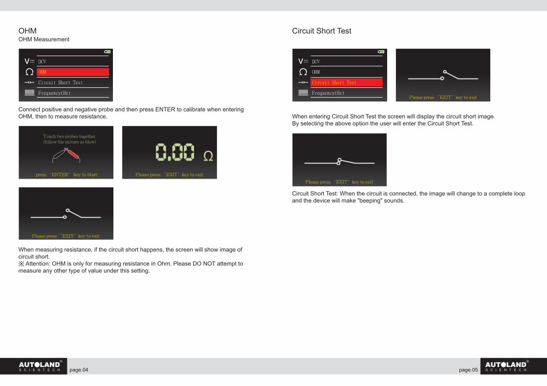
OHMOHM Measurement
Connect positive and negative probe and then press ENTER to calibrate when entering OHM, then to measure resistance.
When measuring resistance, if the circuit short happens, the screen will show image of circuit short. ※ Attention: OHM is only for measuring resistance in Ohm. Please DO NOT attempt to measure any other type of value under this setting.
Circuit Short Test
When entering Circuit Short Test the screen will display the circuit short image. By selecting the above option the user will enter the Circuit Short Test.
Circuit Short Test: When the circuit is connected, the image will change to a complete loop and the device will make "beeping" sounds.
DCV
OHM
Circuit Short Test
Frequency(Hz)
Please press ‘EXIT’key to exitpress ‘ENTER’ key to Start
Touch two probes together(follow the picture as blow)
Please press ‘EXIT’key to exit
DCV
OHM
Circuit Short Test
Frequency(Hz)Please press ‘EXIT’key to exit
Please press ‘EXIT’key to exit
page. page.06 07
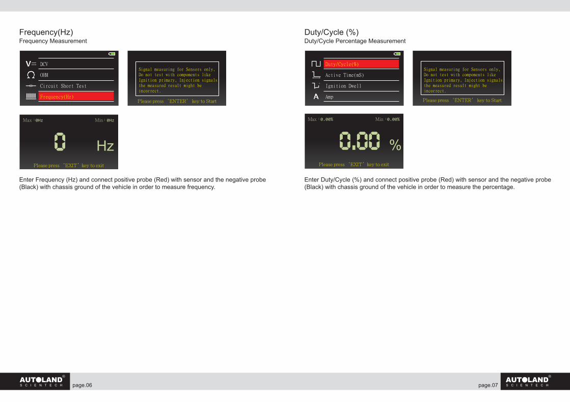
Frequency(Hz) Frequency Measurement
Enter Frequency (Hz) and connect positive probe (Red) with sensor and the negative probe (Black) with chassis ground of the vehicle in order to measure frequency.
Duty/Cycle (%)Duty/Cycle Percentage Measurement
Enter Duty/Cycle (%) and connect positive probe (Red) with sensor and the negative probe (Black) with chassis ground of the vehicle in order to measure the percentage.
0 HzPlease press ‘EXIT’key to exit
Max:0Hz Min:0Hz
DCV
OHM
Circuit Short Test
Frequency(Hz)
Signal measuring for Sensors only,Do not test with compoments likeIgnition primary, Injection signals,the measured result might beincorrect.
Please press ‘ENTER’ key to Start
0.00 %Please press ‘EXIT’key to exit
Max:0.00% Min:0.00%
Signal measuring for Sensors only,Do not test with compoments likeIgnition primary, Injection signals,the measured result might beincorrect.
Please press ‘ENTER’ key to Start
Duty/Cycle(%)
Active Time(mS)
Ignition Dwell
Amp
o
page. page.08 09
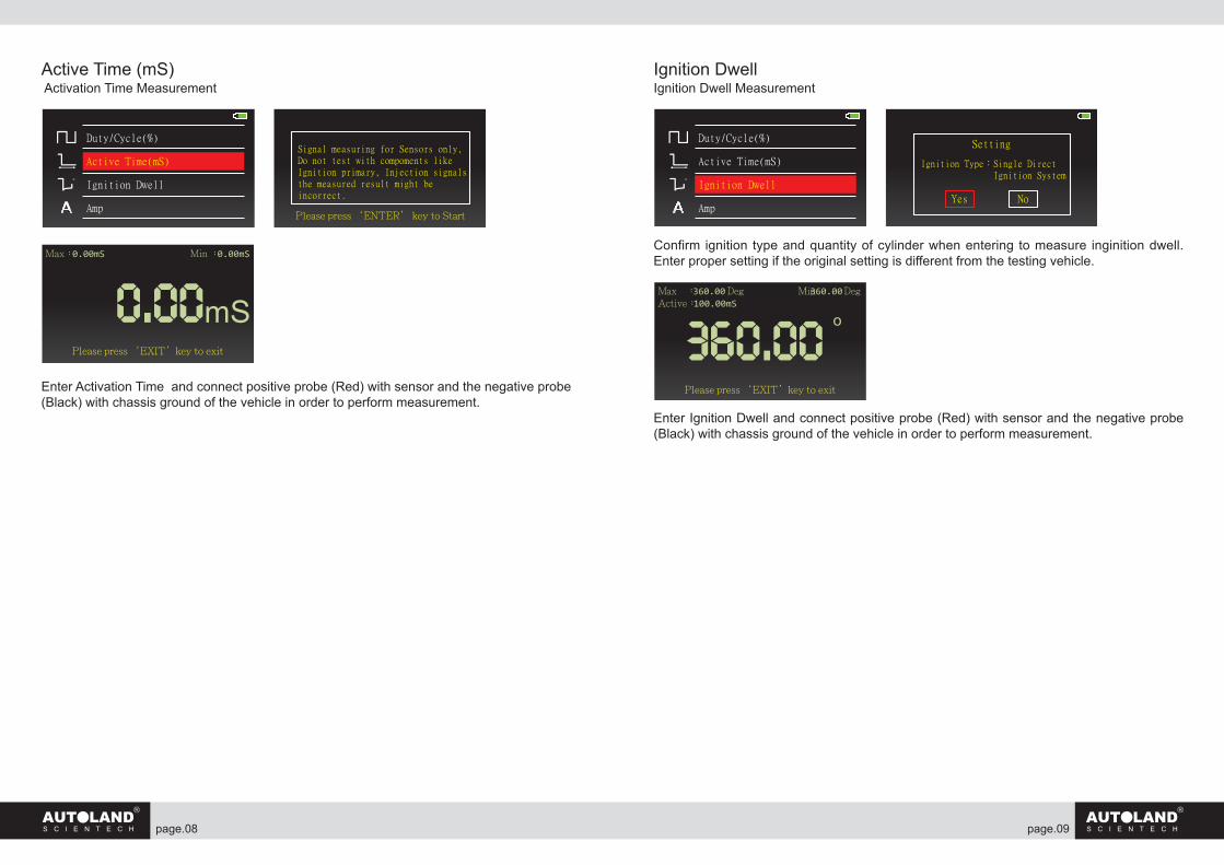
Active Time (mS) Activation Time Measurement
Enter Activation Time and connect positive probe (Red) with sensor and the negative probe (Black) with chassis ground of the vehicle in order to perform measurement.
Ignition DwellIgnition Dwell Measurement
Confirm ignition type and quantity of cylinder when entering to measure inginition dwell. Enter proper setting if the original setting is different from the testing vehicle.
Enter Ignition Dwell and connect positive probe (Red) with sensor and the negative probe (Black) with chassis ground of the vehicle in order to perform measurement.
0.00mSPlease press ‘EXIT’key to exit
Max:0.00mS Min :0.00mS
Signal measuring for Sensors only,Do not test with compoments likeIgnition primary, Injection signals,the measured result might beincorrect.
Please press ‘ENTER’ key to Start
Duty/Cycle(%)
Active Time(mS)
Ignition Dwell
Amp
o
Duty/Cycle(%)
Active Time(mS)
Ignition Dwell
Amp
o
Setting
Ignition Type:Single Direct Ignition System
Yes No
360.00 o
Please press ‘EXIT’key to exit
Max :360.00 Deg Min:360.00 Deg Active:100.00mS
page. page.10 11
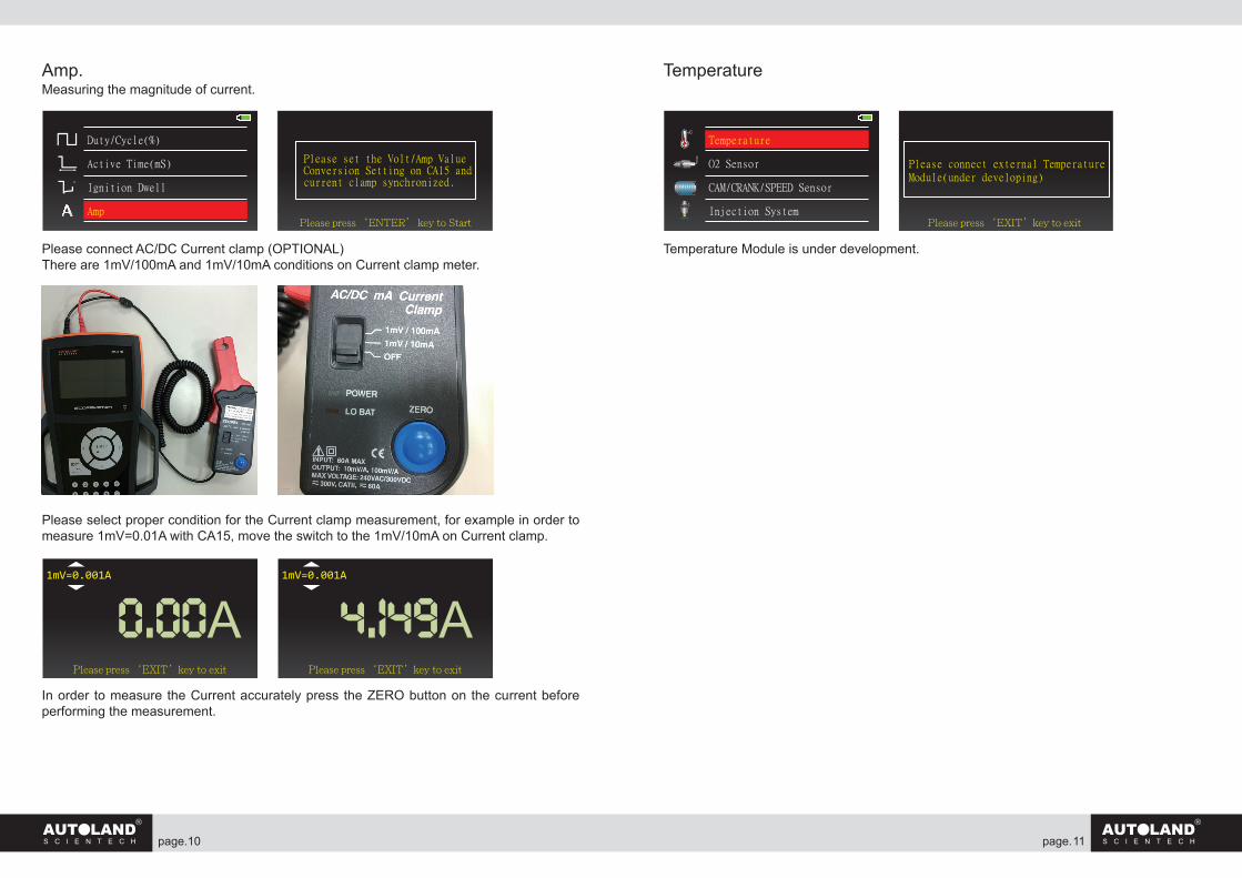
Amp.Measuring the magnitude of current.
Please connect AC/DC Current clamp (OPTIONAL)There are 1mV/100mA and 1mV/10mA conditions on Current clamp meter.
Please select proper condition for the Current clamp measurement, for example in order to measure 1mV=0.01A with CA15, move the switch to the 1mV/10mA on Current clamp.
In order to measure the Current accurately press the ZERO button on the current before performing the measurement.
Temperature
Temperature Module is under development.
Please set the Volt/Amp ValueConversion Setting on CA15 andcurrent clamp synchronized.
Please press ‘ENTER’ key to Start
Duty/Cycle(%)
Active Time(mS)
Ignition Dwell
Amp
o
0.00A1mV=0.001A
Please press ‘EXIT’key to exit
4.149A1mV=0.001A
Please press ‘EXIT’key to exit
Temperature
O2 Sensor
CAM/CRANK/SPEED Sensor
Injection System
oC
Please connect external TemperatureModule(under developing)
Please press ‘EXIT’key to exit
page. page.12 13
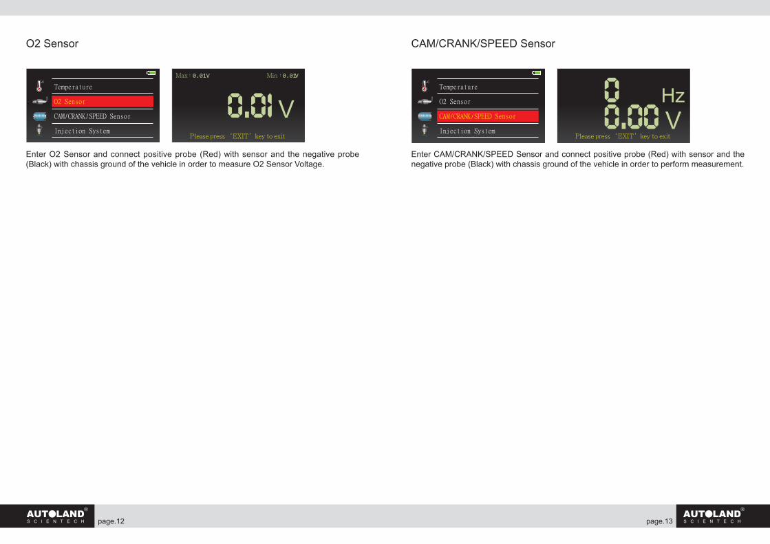
O2 Sensor
Enter O2 Sensor and connect positive probe (Red) with sensor and the negative probe (Black) with chassis ground of the vehicle in order to measure O2 Sensor Voltage.
CAM/CRANK/SPEED Sensor
Enter CAM/CRANK/SPEED Sensor and connect positive probe (Red) with sensor and the negative probe (Black) with chassis ground of the vehicle in order to perform measurement.
Temperature
O2 Sensor
CAM/CRANK/SPEED Sensor
Injection System
oC
0.01 VPlease press ‘EXIT’key to exit
Max:0.01V Min:0.01V
Temperature
O2 Sensor
CAM/CRANK/SPEED Sensor
Injection System
oC
0 Hz0.00 V
Please press ‘EXIT’key to exit
page. page.14 15
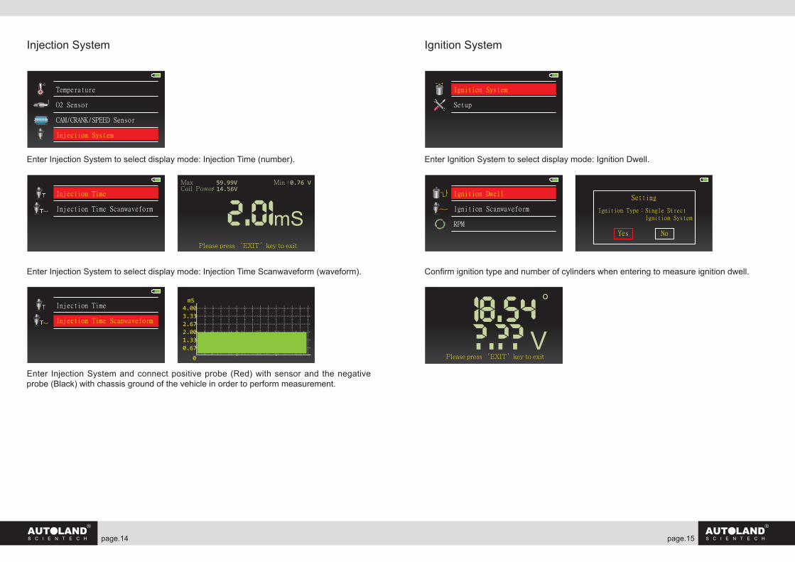
Injection System
Enter Injection System to select display mode: Injection Time (number).
Enter Injection System to select display mode: Injection Time Scanwaveform (waveform).
Enter Injection System and connect positive probe (Red) with sensor and the negative probe (Black) with chassis ground of the vehicle in order to perform measurement.
Ignition System
Enter Ignition System to select display mode: Ignition Dwell.
Confirm ignition type and number of cylinders when entering to measure ignition dwell.
Temperature
O2 Sensor
CAM/CRANK/SPEED Sensor
Injection System
oC
Injection Time
Injection Time Scanwaveform 2.01mSPlease press ‘EXIT’key to exit
Max :59.99V Min:0.76 VCoil Power:14.56V
Injection Time
Injection Time Scanwaveform
4.003.332.672.001.330.67
0
mS
Ignition System
Setup
Setting
Ignition Type:Single Direct Ignition System
Yes No
Ignition Dwell
Ignition Scanwaveform
RPM
18.54 o
?.?? VPlease press ‘EXIT’key to exit
page. page.16 17
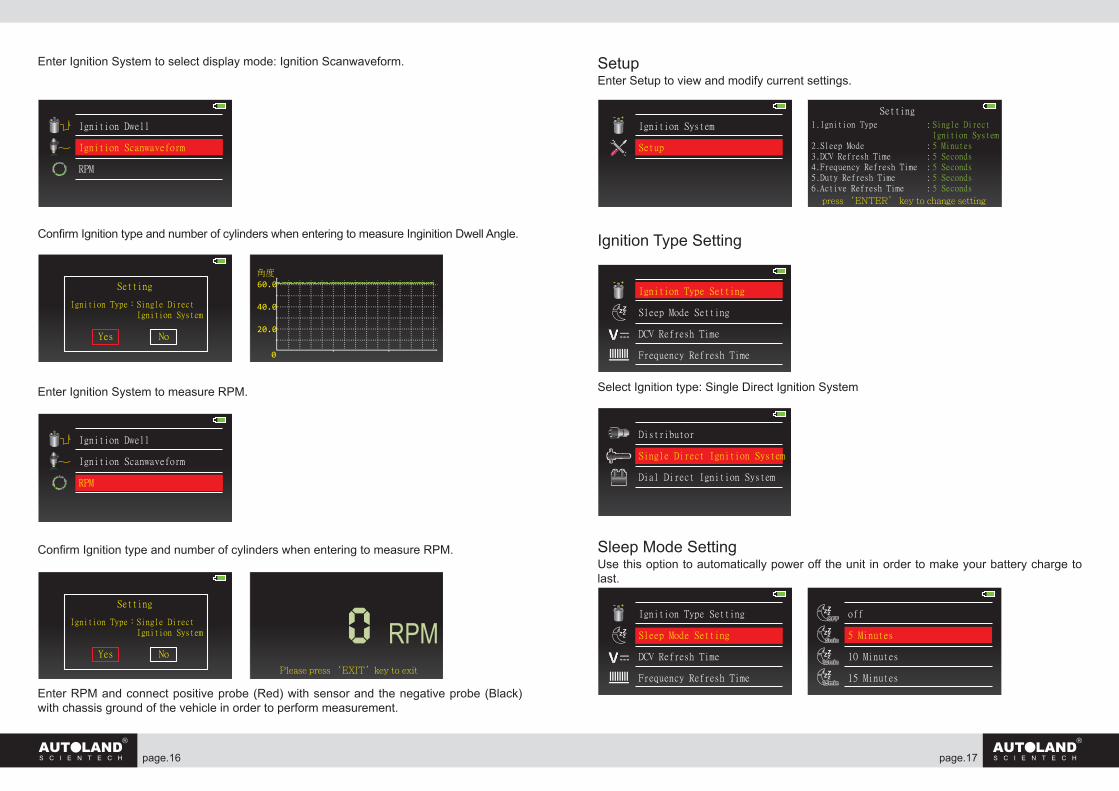
Enter Ignition System to select display mode: Ignition Scanwaveform.
Confirm Ignition type and number of cylinders when entering to measure Inginition Dwell Angle.
Enter Ignition System to measure RPM.
Confirm Ignition type and number of cylinders when entering to measure RPM.
Enter RPM and connect positive probe (Red) with sensor and the negative probe (Black) with chassis ground of the vehicle in order to perform measurement.
Ignition Dwell
Ignition Scanwaveform
RPM
Setting
Ignition Type:Single Direct Ignition System
Yes No
60.0
40.0
20.0
0
角度
Ignition Dwell
Ignition Scanwaveform
RPM
Setting
Ignition Type:Single Direct Ignition System
Yes No
0 RPMPlease press ‘EXIT’key to exit
SetupEnter Setup to view and modify current settings.
Ignition Type Setting
Select Ignition type: Single Direct Ignition System
Sleep Mode SettingUse this option to automatically power off the unit in order to make your battery charge to last.
Ignition System
Setup
Setting
1.Ignition Type :
2.Sleep Mode :3.DCV Refresh Time :4.Frequency Refresh Time :5.Duty Refresh Time :6.Active Refresh Time :
Single DirectIgnition System5 Minutes5 Seconds5 Seconds5 Seconds5 Seconds
press ‘ENTER’ key to change setting
Ignition Type Setting
Sleep Mode Setting
DCV Refresh Time
Frequency Refresh Time
ZZZ
Distributor
Single Direct Ignition System
Dial Direct Ignition System
Ignition Type Setting
Sleep Mode Setting
DCV Refresh Time
Frequency Refresh Time
ZZZ
off
5 Minutes
10 Minutes
15 Minutes
ZZZ

page. page.18 19
DCV Refresh Time
Frequency Refresh Time
Duty Refresh Time
Active Time Refresh Time
Ignition Type Setting
Sleep Mode Setting
DCV Refresh Time
Frequency Refresh Time
ZZZ
5 Seconds
25 Seconds
45 Seconds
1 Minutes
O2 Refresh Time
Ignition Dwell Refresh Time
Duty Refresh Time
Active Time Refresh Time
O2 Refresh Time
Ignition Dwell Refresh Timeo
5 Seconds
25 Seconds
45 Seconds
1 Minutes
o
o
o
o
Duty Refresh Time
Active Time Refresh Time
O2 Refresh Time
Ignition Dwell Refresh Timeo
5 Seconds
25 Seconds
45 Seconds
1 Minutes
Duty Refresh Time
Active Time Refresh Time
O2 Refresh Time
Ignition Dwell Refresh Timeo
5 Seconds
25 Seconds
45 Seconds
1 Minutes
Duty Refresh Time
Active Time Refresh Time
O2 Refresh Time
Ignition Dwell Refresh Timeo
5 Seconds
25 Seconds
45 Seconds
1 Minutes
Ignition Type Setting
Sleep Mode Setting
DCV Refresh Time
Frequency Refresh Time
ZZZ
5 Seconds
25 Seconds
45 Seconds
1 Minutes
page. page.20 21
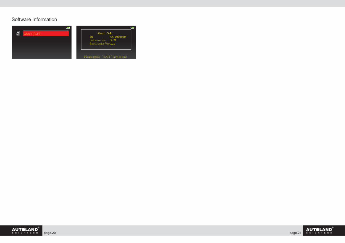
Software Information
About CA15 About CA15SN :CA-00000007Software Ver :1.25BootLoader Ver:1.1
Please press ‘EXIT’key to exit
page. page.22 23
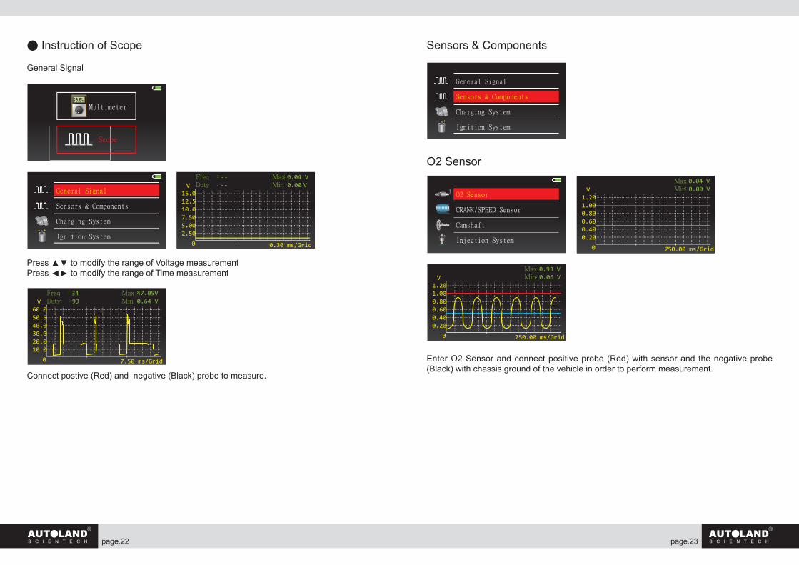
● Instruction of Scope
General Signal
Press ▲▼ to modify the range of Voltage measurementPress ◄► to modify the range of Time measurement
Connect postive (Red) and negative (Black) probe to measure.
Sensors & Components
O2 Sensor
Enter O2 Sensor and connect positive probe (Red) with sensor and the negative probe (Black) with chassis ground of the vehicle in order to perform measurement.
General Signal
Sensors & Components
Charging System
Ignition System
15.012.510.07.505.002.50
0
Max:0.04 V Min :0.00 V
0.30 ms/Grid
Freq :-- Duty :--V
13.8VMultimeter
Scope
60.050.540.030.020.010.0
0
Max:47.05V Min :0.64 V
7.50 ms/Grid
Freq :34 Duty :93V
General Signal
Sensors & Components
Charging System
Ignition System
1.201.000.800.600.400.20
0
Max:0.04 V Min :0.00 V
750.00 ms/Grid
V
1.201.000.800.600.400.20
0
Max:0.93 V Min :0.06 V
750.00 ms/Grid
V
O2 Sensor
CRANK/SPEED Sensor
Camshaft
Injection System
page. page.24 25
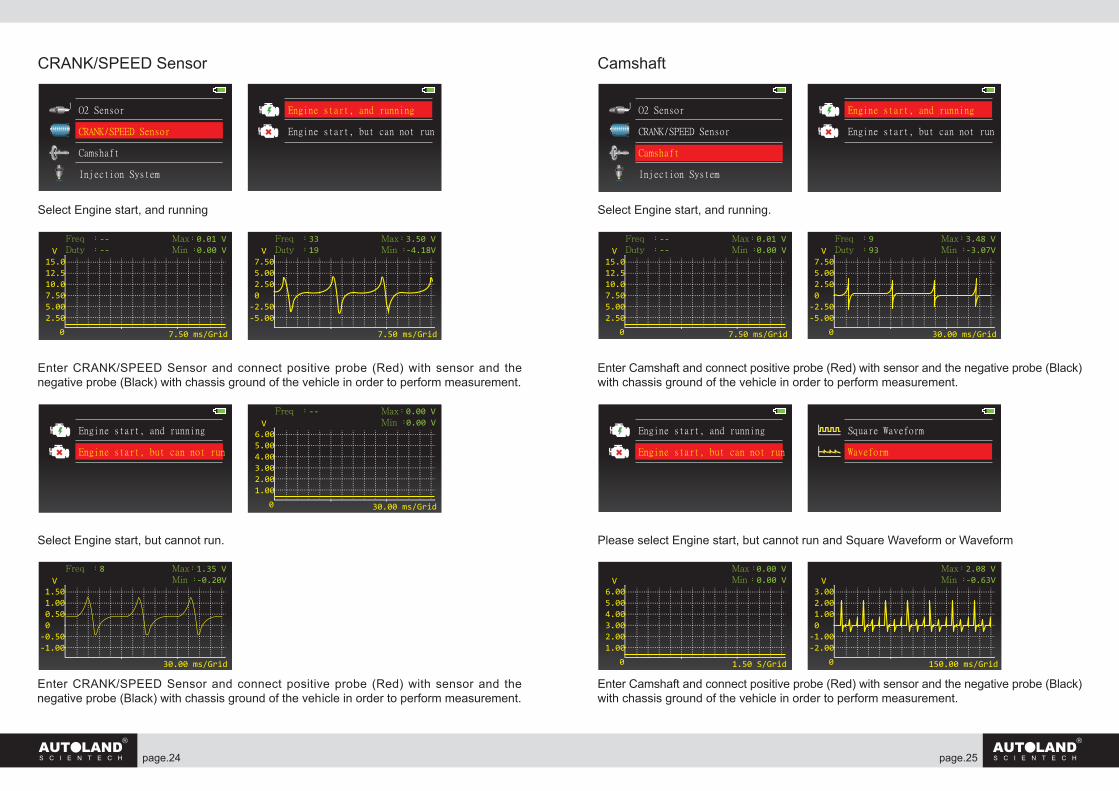
CRANK/SPEED Sensor
Select Engine start, and running
Enter CRANK/SPEED Sensor and connect positive probe (Red) with sensor and the negative probe (Black) with chassis ground of the vehicle in order to perform measurement.
Select Engine start, but cannot run.
Enter CRANK/SPEED Sensor and connect positive probe (Red) with sensor and the negative probe (Black) with chassis ground of the vehicle in order to perform measurement.
Camshaft
Select Engine start, and running.
Enter Camshaft and connect positive probe (Red) with sensor and the negative probe (Black) with chassis ground of the vehicle in order to perform measurement.
Please select Engine start, but cannot run and Square Waveform or Waveform
Enter Camshaft and connect positive probe (Red) with sensor and the negative probe (Black) with chassis ground of the vehicle in order to perform measurement.
O2 Sensor
CRANK/SPEED Sensor
Camshaft
Injection System
Engine start, and running
Engine start, but can not run
15.012.510.07.505.002.50
0
Max:0.01 VMin :0.00 V
7.50 ms/Grid
Freq :-- Duty :--V
7.50 5.00 2.50 0-2.50-5.00
Max:3.50 VMin :-4.18V
7.50 ms/Grid
Freq :33 Duty :19V
Engine start, and running
Engine start, but can not run
6.005.004.003.002.001.00
0
Max:0.00 VMin :0.00 V
30.00 ms/Grid
Freq :-- V
1.50 1.00 0.50 0-0.50-1.00
Max:1.35 VMin :-0.20V
30.00 ms/Grid
Freq :8 V
O2 Sensor
CRANK/SPEED Sensor
Camshaft
Injection System
Engine start, and running
Engine start, but can not run
15.012.510.07.505.002.50
0
Max:0.01 VMin :0.00 V
7.50 ms/Grid
Freq :-- Duty :--V
7.50 5.00 2.50 0-2.50-5.00
0
Max:3.48 VMin :-3.07V
30.00 ms/Grid
Freq :9 Duty :93V
Engine start, and running
Engine start, but can not run
Square Waveform
Waveform
6.005.004.003.002.001.00
0
Max:0.00 VMin :0.00 V
1.50 S/Grid
V 3.00 2.00 1.00 0-1.00-2.00
0
Max:2.08 VMin :-0.63V
150.00 ms/Grid
V
page. page.26 27
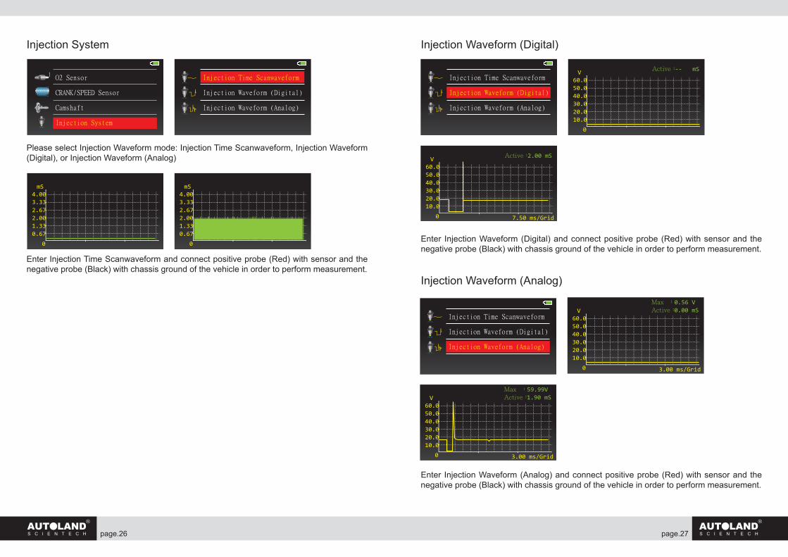
Injection System
Please select Injection Waveform mode: Injection Time Scanwaveform, Injection Waveform (Digital), or Injection Waveform (Analog)
Enter Injection Time Scanwaveform and connect positive probe (Red) with sensor and the negative probe (Black) with chassis ground of the vehicle in order to perform measurement.
Injection Waveform (Digital)
Enter Injection Waveform (Digital) and connect positive probe (Red) with sensor and the negative probe (Black) with chassis ground of the vehicle in order to perform measurement.
Injection Waveform (Analog)
Enter Injection Waveform (Analog) and connect positive probe (Red) with sensor and the negative probe (Black) with chassis ground of the vehicle in order to perform measurement.
O2 Sensor
CRANK/SPEED Sensor
Camshaft
Injection System
Injection Time Scanwaveform
Injection Waveform (Digital)
Injection Waveform (Analog)
4.003.332.672.001.330.67
0
mS4.003.332.672.001.330.67
0
mS
60.050.040.030.020.010.0
0
Active:-- mSV
60.050.040.030.020.010.0
0
Active:2.00 mS
7.50 ms/Grid
V
Injection Time Scanwaveform
Injection Waveform (Digital)
Injection Waveform (Analog)
60.050.040.030.020.010.0
0
Max :0.56 VActive:0.00 mS
3.00 ms/Grid
V
60.050.040.030.020.010.0
0
Max :59.99VActive:1.90 mS
3.00 ms/Grid
V
Injection Time Scanwaveform
Injection Waveform (Digital)
Injection Waveform (Analog)
page. page.28 29
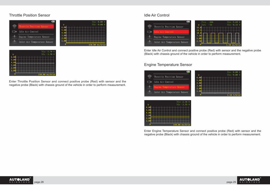
Throttle Position Sensor
Enter Throttle Position Sensor and connect positive probe (Red) with sensor and the negative probe (Black) with chassis ground of the vehicle in order to perform measurement.
Idle Air Control
Enter Idle Air Control and connect positive probe (Red) with sensor and the negative probe (Black) with chassis ground of the vehicle in order to perform measurement.
Engine Temperature Sensor
Enter Engine Temperature Sensor and connect positive probe (Red) with sensor and the negative probe (Black) with chassis ground of the vehicle in order to perform measurement.
6.005.004.003.002.001.00
0
Max:0.00 VMin :0.00 V
150.00 ms/Grid
V
6.005.004.003.002.001.00
0
Max:3.70 VMin :3.70 V
150.00 ms/Grid
V
Throttle Position Sensor
Idle Air Control
Engine Temperature Sensor
Inlet Air Temperature Sensor
15.012.510.07.505.002.50
0
Max:9.69 VMin :0.33 V
1.50 ms/Grid
Freq :244 Duty :53V
Throttle Position Sensor
Idle Air Control
Engine Temperature Sensor
Inlet Air Temperature Sensor
6.005.004.003.002.001.00
0
Max:0.00 VMax:0.00 V
1.50 S/Grid
V
6.005.004.003.002.001.00
0
Max:2.36 VMin :2.35 V
150.00 ms/Grid
V
Throttle Position Sensor
Idle Air Control
Engine Temperature Sensor
Inlet Air Temperature Sensor
page. page.30 31
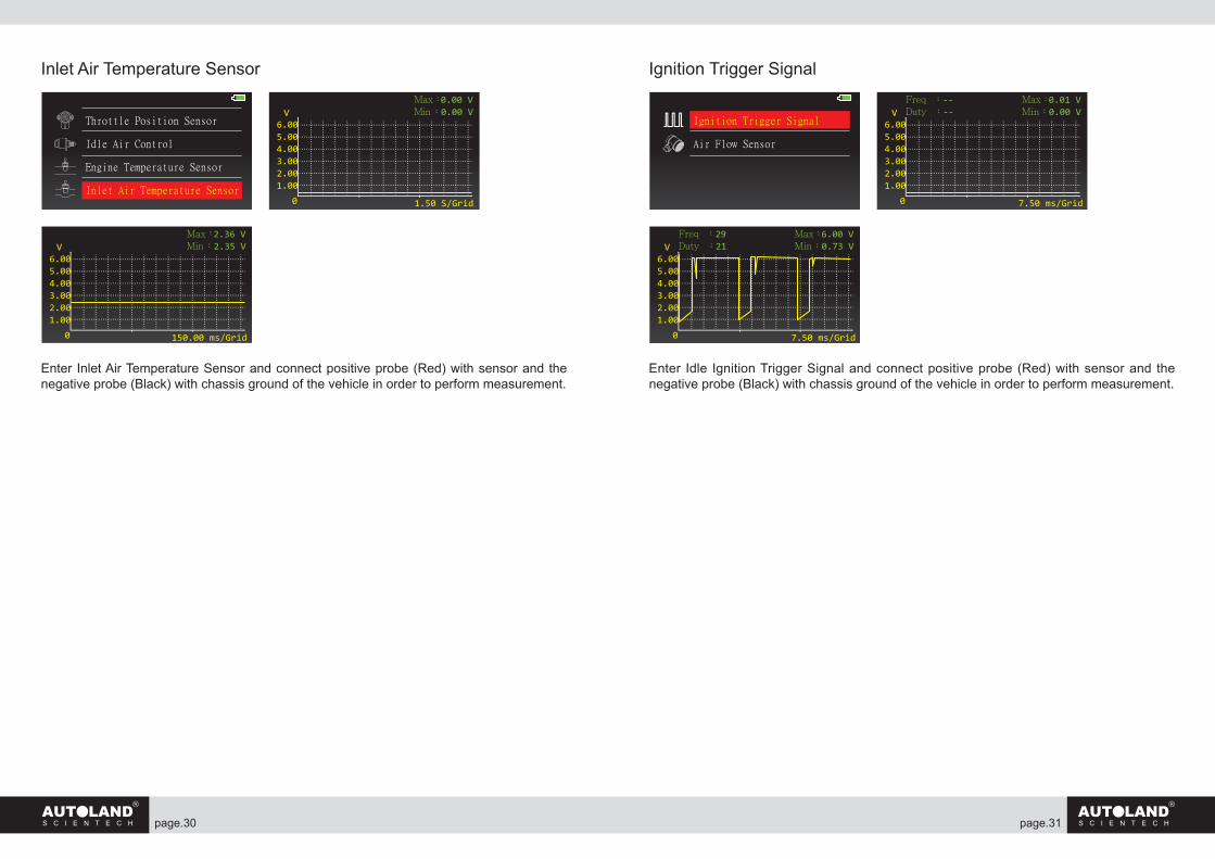
Inlet Air Temperature Sensor
Enter Inlet Air Temperature Sensor and connect positive probe (Red) with sensor and the negative probe (Black) with chassis ground of the vehicle in order to perform measurement.
Ignition Trigger Signal
Enter Idle Ignition Trigger Signal and connect positive probe (Red) with sensor and the negative probe (Black) with chassis ground of the vehicle in order to perform measurement.
6.005.004.003.002.001.00
0
Max:0.00 VMin :0.00 V
1.50 S/Grid
V
6.005.004.003.002.001.00
0
Max:2.36 VMin :2.35 V
150.00 ms/Grid
V
Throttle Position Sensor
Idle Air Control
Engine Temperature Sensor
Inlet Air Temperature Sensor
6.005.004.003.002.001.00
0
Max:0.01 VMin :0.00 V
7.50 ms/Grid
VFreq :-- Duty :--
6.005.004.003.002.001.00
0
Max:6.00 VMin :0.73 V
7.50 ms/Grid
VFreq :29 Duty :21
Ignition Trigger Signal
Air Flow Sensor
page. page.32 33
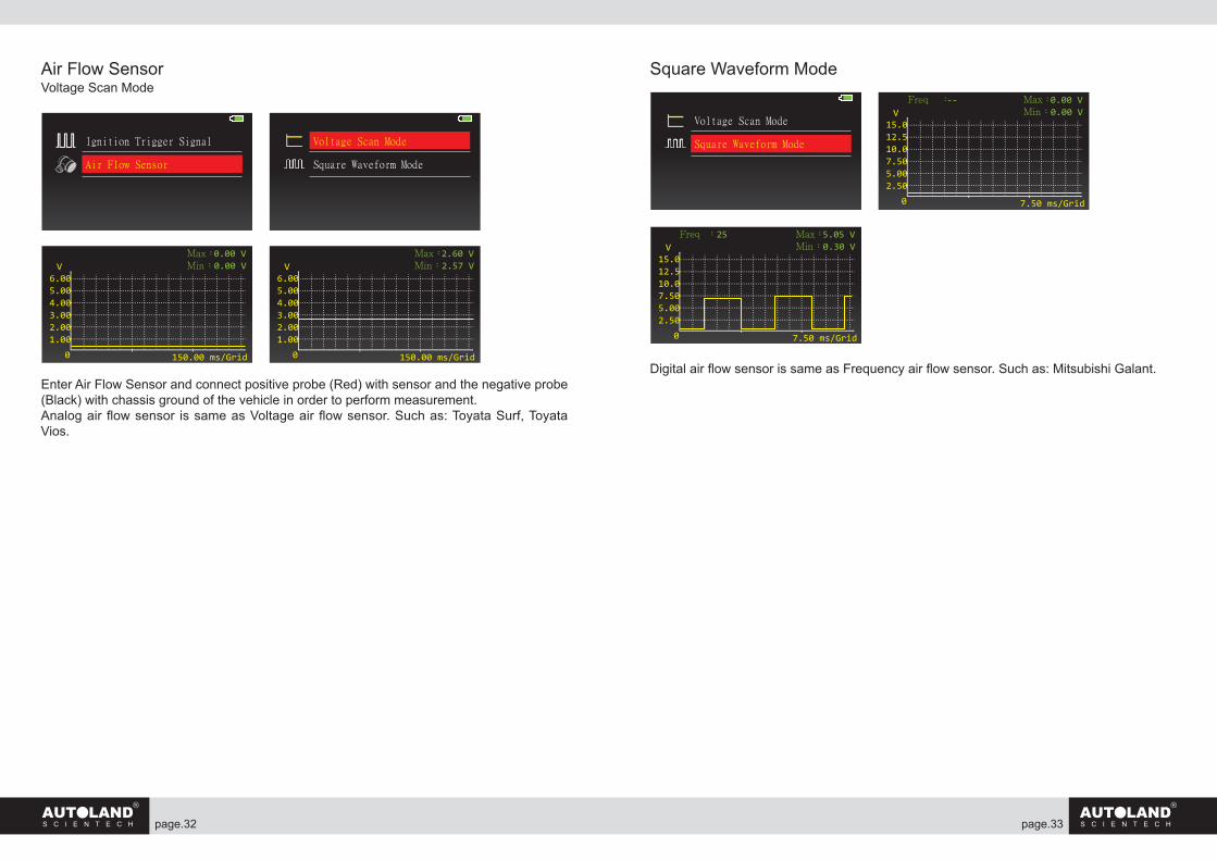
Air Flow SensorVoltage Scan Mode
Enter Air Flow Sensor and connect positive probe (Red) with sensor and the negative probe (Black) with chassis ground of the vehicle in order to perform measurement.Analog air flow sensor is same as Voltage air flow sensor. Such as: Toyata Surf, Toyata Vios.
Square Waveform Mode
Digital air flow sensor is same as Frequency air flow sensor. Such as: Mitsubishi Galant.
6.005.004.003.002.001.00
0
Max:0.00 VMin :0.00 V
150.00 ms/Grid
V6.005.004.003.002.001.00
0
Max:2.60 VMin :2.57 V
150.00 ms/Grid
V
Ignition Trigger Signal
Air Flow Sensor
Voltage Scan Mode
Square Waveform Mode
15.012.510.07.505.002.50
0
Max:0.00 VMin :0.00 V
7.50 ms/Grid
VFreq :--
15.012.510.07.505.002.50
0
Max:5.05 VMin :0.30 V
7.50 ms/Grid
VFreq :25
Voltage Scan Mode
Square Waveform Mode
page. page.34 35
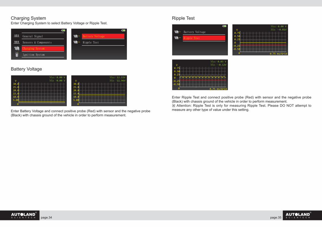
Charging SystemEnter Charging System to select Battery Voltage or Ripple Test.
Battery Voltage
Enter Battery Voltage and connect positive probe (Red) with sensor and the negative probe (Black) with chassis ground of the vehicle in order to perform measurement.
Ripple Test
Enter Ripple Test and connect positive probe (Red) with sensor and the negative probe (Black) with chassis ground of the vehicle in order to perform measurement.※ Attention: Ripple Test is only for measuring Ripple Test. Please DO NOT attempt to measure any other type of value under this setting.
General Signal
Sensors & Components
Charging System
Ignition System
Battery Voltage
Ripple Test
30.025.020.015.010.05.00
0
Max:0.00 VMin :0.00 VV
30.025.020.015.010.05.00
0
Max:12.11VMin :11.96VV
0.75 0.50 0.25 0-0.25-0.50
0
Max:0.00 VMin :-0.01V
0.75 ms/Grid
VBattery Voltage
Ripple Test
0.75 0.50 0.25 0-0.25-0.50
0
Max:0.03 VMin :-0.12V
0.75 ms/Grid
V
page. page.36 37
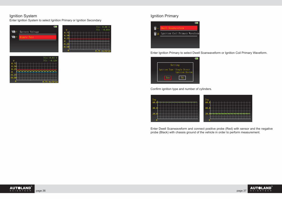
Ignition SystemEnter Ignition System to select Ignition Primary or Ignition Secondary
Ignition Primary
Enter Ignition Primary to select Dwell Scanwaveform or Ignition Coil Primary Waveform.
Confirm ignition type and number of cylinders.
Enter Dwell Scanwaveform and connect positive probe (Red) with sensor and the negative probe (Black) with chassis ground of the vehicle in order to perform measurement.
0.75 0.50 0.25 0-0.25-0.50
0
Max:0.00 VMin :-0.01V
0.75 ms/Grid
VBattery Voltage
Ripple Test
0.75 0.50 0.25 0-0.25-0.50
0
Max:0.03 VMin :-0.12V
0.75 ms/Grid
V
Dwell Scanwaveform
Ignition Coil Primary Waveform
Setting
Ignition Type:Single Direct Ignition System
Yes No
60.0
40.0
20.0
0
Deg60.0
40.0
20.0
0
Deg
page. page.38 39
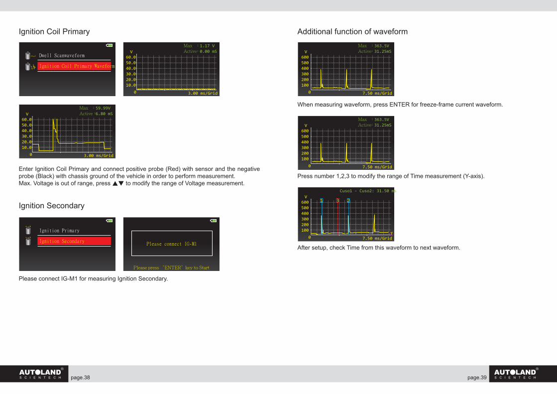
Ignition Coil Primary
Enter Ignition Coil Primary and connect positive probe (Red) with sensor and the negative probe (Black) with chassis ground of the vehicle in order to perform measurement.Max. Voltage is out of range, press ▲▼ to modify the range of Voltage measurement.
Ignition Secondary
Please connect IG-M1 for measuring Ignition Secondary.
Additional function of waveform
When measuring waveform, press ENTER for freeze-frame current waveform.
Press number 1,2,3 to modify the range of Time measurement (Y-axis).
After setup, check Time from this waveform to next waveform.
60.050.040.030.020.010.0
0
Max :1.17 VActive:0.00 mS
3.00 ms/Grid
VDwell Scanwaveform
Ignition Coil Primary Waveform
60.050.040.030.020.010.0
0
Max :59.99VActive:6.80 mS
3.00 ms/Grid
V
Ignition Primary
Ignition SecondaryPlease connect IG-M1
Please press ‘ENTER’key to Start
600500400300200100
0
Max :363.5VActive:31.25mS
7.50 ms/Grid
V
600500400300200100
0
Max :363.5VActive:31.25mS
7.50 ms/Grid
V
600500400300200100
0
Cuso1 - Cuso2: 31.50 ms
7.50 ms/Grid
V3
T
1 2
page. page.40 41
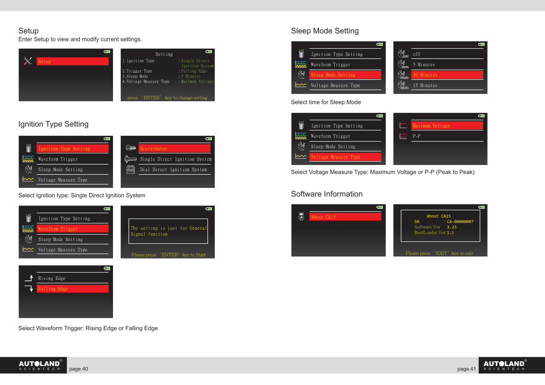
SetupEnter Setup to view and modify current settings.
Ignition Type Setting
Select Ignition type: Single Direct Ignition System
Select Waveform Trigger: Rising Edge or Falling Edge
Sleep Mode Setting
Select time for Sleep Mode
Select Voltage Measure Type: Maximum Voltage or P-P (Peak to Peak)
Software Information
Setup
Setting
1.Ignition Type :
2.Trigger Type :3.Sleep Mode :4.Voltage Measure Type :
Single DirectIgnition SystemFalling Edge5 MinutesMaximum Voltage
press ‘ENTER’ key to change setting
Ignition Type Setting
Waveform Trigger
Sleep Mode Setting
Voltage Measure Type
Distributor
Single Direct Ignition System
Dial Direct Ignition System
Ignition Type Setting
Waveform Trigger
Sleep Mode Setting
Voltage Measure Type
off
5 Minutes
10 Minutes
15 Minutes
ZZZ
About CA15SN :CA-00000007Software Ver :1.25BootLoader Ver:1.1
Please press ‘EXIT’key to exit
About CA15
The setting is just for GeneralSignal function
Please press ‘ENTER’key to Start
Ignition Type Setting
Waveform Trigger
Sleep Mode Setting
Voltage Measure Type
Rising Edge
Falling Edge
Ignition Type Setting
Waveform Trigger
Sleep Mode Setting
Voltage Measure Type
Maximum Voltage
P-P
page. page.42 43
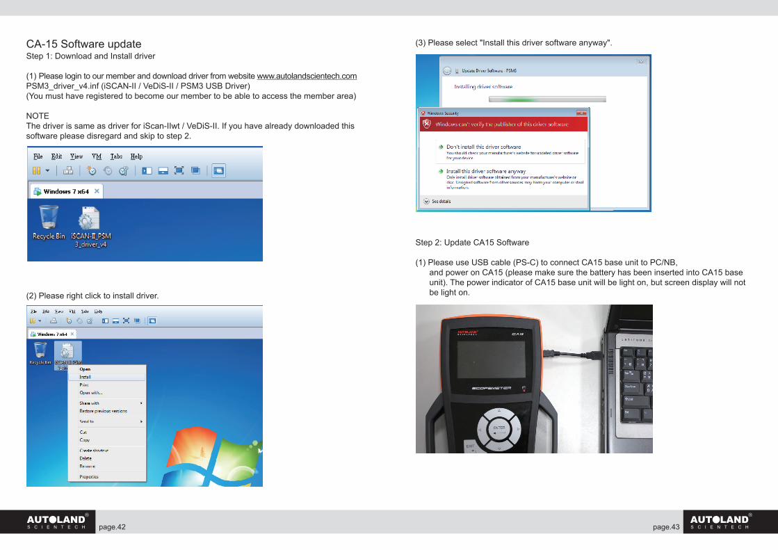
CA-15 Software updateStep 1: Download and Install driver
(1) Please login to our member and download driver from website www.autolandscientech.com PSM3_driver_v4.inf (iSCAN-II / VeDiS-II / PSM3 USB Driver)(You must have registered to become our member to be able to access the member area) NOTEThe driver is same as driver for iScan-IIwt / VeDiS-II. If you have already downloaded this software please disregard and skip to step 2.
(2) Please right click to install driver.
(3) Please select "Install this driver software anyway".
Step 2: Update CA15 Software
(1) Please use USB cable (PS-C) to connect CA15 base unit to PC/NB, and power on CA15 (please make sure the battery has been inserted into CA15 base unit). The power indicator of CA15 base unit will be light on, but screen display will not be light on.
page. page.44 45
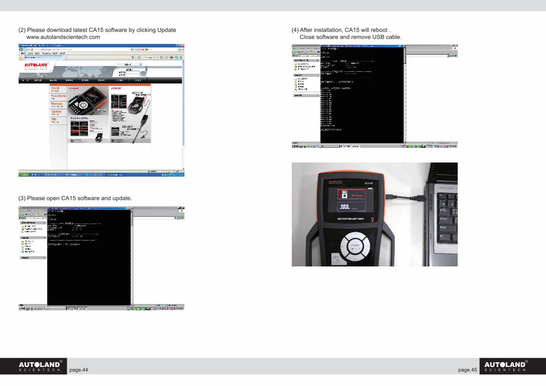
(2) Please download latest CA15 software by clicking Update www.autolandscientech.com
(3) Please open CA15 software and update.
(4) After installation, CA15 will reboot . Close software and remove USB cable.
page. page.46 47
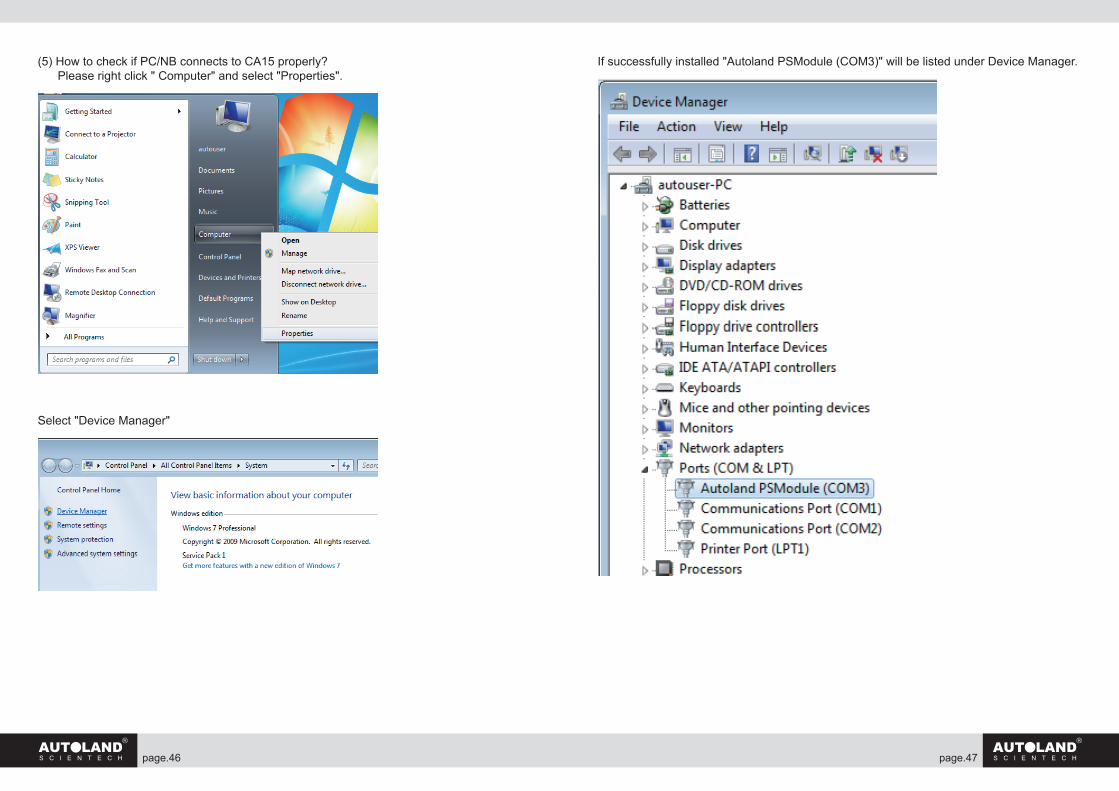
(5) How to check if PC/NB connects to CA15 properly? Please right click " Computer" and select "Properties".
Select "Device Manager"
If successfully installed "Autoland PSModule (COM3)" will be listed under Device Manager.