Embed Size (px)
Citation preview
End User Interaction Tutorial
CA BEST PRACTICES
CA IT Process
Automation Manager
START REQUEST FORM
INTERACTION REQUEST FORM
EMAIL ALERT
PROCESS DATASET
PARAMETERS
THIS IS A DRAFT DOCUMENT – FEEDBACK IS WELCOME
LEGAL NOTICE
This publication is based on current information and resource allocations as of its date of publication and
is subject to change or withdrawal by CA at any time without notice. The information in this publication
could include typographical errors or technical inaccuracies. CA may make modifications to any CA
product, software program, method or procedure described in this publication at any time without
notice.
Any reference in this publication to non-CA products and non-CA websites are provided for convenience
only and shall not serve as CA’s endorsement of such products or websites. Your use of such products,
websites, and any information regarding such products or any materials provided with such products or
at such websites shall be at your own risk.
Notwithstanding anything in this publication to the contrary, this publication shall not (i) constitute
product documentation or specifications under any existing or future written license agreement or
services agreement relating to any CA software product, or be subject to any warranty set forth in any
such written agreement; (ii) serve to affect the rights and/or obligations of CA or its licensees under
any existing or future written license agreement or services agreement relating to any CA software
product; or (iii) serve to amend any product documentation or specifications for any CA software
product. The development, release and timing of any features or functionality described in this
publication remain at CA’s sole discretion.
The information in this publication is based upon CA’s experiences with the referenced software
products in a variety of development and customer environments. Past performance of the software
products in such development and customer environments is not indicative of the future performance of
such software products in identical, similar or different environments. CA does not warrant that the
software products will operate as specifically set forth in this publication. CA will support only the
referenced products in accordance with (i) the documentation and specifications provided with the
referenced product, and (ii) CA’s then-current maintenance and support policy for the referenced
product.
Certain information in this publication may outline CA’s general product direction. All information in this
publication is for your informational purposes only and may not be incorporated into any contract. CA
assumes no responsibility for the accuracy or completeness of the information. To the extent permitted
by applicable law, CA provides this document “AS IS” without warranty of any kind, including, without
limitation, any implied warranties of merchantability, fitness for a particular purpose, or non-
infringement. In no event will CA be liable for any loss or damage, direct or indirect, from the use of
this document, including, without limitation, lost profits, lost investment, business interruption, goodwill
or lost data, even if CA is expressly advised of the possibility of such damages.
COPYRIGHT LICENSE AND NOTICE:
This publication may contain sample application programming code and/or language which illustrate
programming techniques on various operating systems. Notwithstanding anything to the contrary
contained in this publication, such sample code does not constitute licensed products or software under
any CA license or services agreement. You may copy, modify and use this sample code for the
purposes of performing the installation methods and routines described in this document. These
samples have not been tested. CA does not make, and you may not rely on, any promise, express or
implied, of reliability, serviceability or function of the sample code.Copyright © 2009 CA. All rights
reserved. All trademarks, trade names, service marks and logos referenced herein belong to their
respective companies. Microsoft product screen shots reprinted with permission from Microsoft
Corporation.
TITLE AND PUBLICATION DATE: CA IT PAM End User Interaction Tutorial 2010-4-1
Publication Date: April 2010
ACKNOWLEDGEMENTS
Principal Authors and Technical Editors
George Curran
Anders Magnusson
CA PRODUCT REFERENCES
This document references the following CA products:
■ CA IT Process Automation Manager™ (CA IT PAM)
FEEDBACK
This is a draft document – feedback is welcome. Please email us at [email protected] to
share your feedback on this publication. Please include the title of this publication in the
subject of your email response. For technical assistance with a CA product, please contact
CA Technical Support at http://ca.com/support. For assistance with support specific to
Japanese operating systems, please contact CA at http://www.casupport.jp.

CA IT Process Automation Manager 5
Contents
CA IT Process Automation Manager End User Interaction Tutorial 7 Overview ...................................................................................................................... 7 Before You Begin ........................................................................................................... 7 Step 1: Planning ............................................................................................................ 8
Example 1 Process Outline ........................................................................................... 9 Step 2: Create Library Folder Structure ............................................................................ 9 Step 3: Create Process and Process Dataset .................................................................... 10 Step 4: Define Parameters to the Process Dataset............................................................ 11
Parameter Data Types ............................................................................................... 11 Parameter Naming .................................................................................................... 11 Parameter Organization ............................................................................................. 12 Check In Updated Process .......................................................................................... 24
Step 5: Create Start Request Form ................................................................................ 24 Create the Start Request Form ................................................................................... 25 Expose User Updatable Objects .................................................................................. 25 Test the Start Request Form ....................................................................................... 27 Check In the Start Request Form ................................................................................ 28
Step 6: Create Approval Form ....................................................................................... 29 Create the Approval Form .......................................................................................... 29 Expose User Updatable Objects .................................................................................. 29 Test the Approval Form ............................................................................................. 31 Check In the Approval Form ....................................................................................... 31
Step 7: Define the Process ............................................................................................ 32 Prepare to Edit the Process ........................................................................................ 32 Add Start and Stop Operators ..................................................................................... 33 Add Email Alert Operator to Notify Approver ................................................................. 34 Add User Interaction Operator to Link Approval Form .................................................... 35 Add the And Condition Operator.................................................................................. 37 Add a Calculation Operator ......................................................................................... 37 Add an Email Alert Operator to Notify End Users ........................................................... 39
Step 8: Define the Process Flow ..................................................................................... 40 Link a Start Operator to the Approver Notification and Approval Operators ....................... 41 Link Approver Notification Failure to an Abnormal Stop .................................................. 41 Link Approval Rejection to an Abnormal Stop ............................................................... 41 Link Approver Notification Success and Approval Acceptance to an And Operator .............. 41 Link the And Operator to a Calculation Operator ........................................................... 42 Link Calculation Operator Failure to an Abnormal Stop ................................................... 42 Link Calculation Operator Success to the End User Email Alert Operator .......................... 42 Link End User Email Alert Operator Failure to an Abnormal Stop ..................................... 42 Link End User Alert Email Alert Operator Success to a Normal Stop ................................. 42 Save Changes and Check In ....................................................................................... 42
Step 9: Test the Process ............................................................................................... 43 Troubleshooting ........................................................................................................... 45
Incorrect Process Flow Example .................................................................................. 45 Initiate the Process ...................................................................................................... 46 Summary .................................................................................................................... 47

CA IT Process Automation Manager 7
CA IT Process Automation
Manager End User Interaction
Tutorial
Overview
CA IT Process Automation Manager (IT PAM) is a powerful and flexible orchestrator that can
be used to automate processes to increase repeatability and reliability by eliminating
manual steps. Processes can be triggered by a calendar or event and designed to run
automatically with no user intervention. However, in the real world, many processes are
initiated by user request and may need to be suspended pending approval to continue.
This document provides a tutorial focusing on using:
■ “Start Request Form” to accept user input and initiate a process
■ “Interaction Request Form” to suspend a process pending additional input and approval
to continue
■ “Alert” operators to notify responsible parties that a process has been suspended
awaiting their input and/or approval to continue
■ “Datasets” to define parameters and store parameters values used in a process
While the examples presented are intentionally simplistic the concepts illustrated can be
used in far more sophisticated solutions.
Before You Begin
A suitable test environment and some familiarity with the CA IT PAM user interfaces are
required in order to make use of the hands-on examples presented in this document. If you
have not already done so you should download the CA IT PAM Quick Start Guide. This guide
takes you through installing a very basic test environment and provides step-by-step
instructions for creating a simple “Hello World” process to familiarize users with the tool
set. Specifically, you will need to have a working knowledge of the following client UI
components and concepts:
■ Configuration Browser
■ Library Browser
■ Process Designer
■ Operator Module Palette
■ Dataset Palette
8 CA IT Process Automation Manager End User Interaction Tutorial 7
The example scenario will make use of email alerts to notify approvers and end users. You
will need to have access to or install an SMTP mail server to successfully run the example
process in the tutorial. Microsoft Windows Server operating systems include an SMTP
server component. Third party SMTP servers are also available for download from various
sources. Installation and configuration of the mail server itself are beyond the scope of this
document.
If an SMTP mail server is available but the server address is not configured or available
during the CA IT PAM installation take the following steps to update CA IT PAM:
1. Launch the ITPAM Client (see Access CA IT Process Automation Manager Client in the
ITPAM Quick Start Guide for details)
2. Open the “Configuration Browser” by selecting File, Configuration Browser from the
ITPA Client menu.
3. Right-click on the “Domain” node in the tree presented in the left-hand “Browser”
palette and select “Lock” from the in-context menu
4. In the right-hand pane select the “Modules” tab
5. Select the “Alert” module from the list of modules and click the “Edit” button that will
appear on the far right
A new “Alert Modules Properties” tab should appear.
6. Click the “Alert Modules Properties” tab and enter the address for the mail server in the
“SMTP Server for outgoing e-mail” textbox.
7. Click Apply
8. Choose File, Save from the menu (or click the “Diskette” (“Save”) icon on the toolbar)
9. Right-click on the “Domain” node in the tree presented in the left-hand “Browser”
palette and select “Unlock” from the in-context menu.
Email alerts used in the examples will fail if they are unable to access a mail server.
Step 1: Planning
Before defining even the simplest process to CA IT PAM, you need to identify the following:
■ How should the process be started or triggered?
■ What inputs will be required?
■ What are the steps in the process that must be automated?
■ What should happen if a step in the process fails?
■ What, if any, user interactions or approvals will be required?
Depending on complexity of the process, available tools and organizational requirements,
planning and documenting the process can require significant effort and involve a number
of people in different roles. For the purposes of our simple example, a basic bulleted list will
suffice.
CA IT Process Automation Manager 9
Example 1 Process Outline
The following steps will be automated:
■ Start Request - Provide a form for a user to initiate a request to take a server offline for
maintenance on a date specified. The user should be able to choose from a list of
servers and enter a date. Once submitted, the process should be suspended pending
approval of the request.
■ Approver Alert - Notify a pre-designated approver via email that a request to take a
server offline for maintenance was submitted. The subject of the email should indicate
that a process is pending awaiting approval. The body of the email should identify the
process name and instance. The notice should direct the approver to an approval form.
If the attempt to generate the email fails the process should be aborted.
■ Approval - The form should include the server name and date specified by the initiating
user. The approver should be able to modify the date but not the server. The
approver should also be able to approve or reject the request. The process should
continue if approved or be aborted if not approved.
■ End User Alert - Notify a pre-defined list of potentially impacted end users via email
that the server will be offline. The subject and message body of the email should
include the server name and date approved for the server to be offline. If the attempt
to generate the email fails the process should be aborted.
Obviously a “production quality” process would be more complex and include somewhat
more sophisticated error handling. However, the objective here is to quickly define and run
a process that includes using objects, operators and techniques that will be commonly used
in “real world” implementations.
Step 2: Create Library Folder Structure
The next step is to create a folder structure in the in the library of the test environment’s
default orchestrator. To do this, launch the CA IT PAM client and navigate to the “Folder”
palette in the “Library Browser”. Create a suitable folder structure to store the objects that
will be created and used in the example. Keep in mind that creating new objects in the root
folder is not recommended.
Tip: An error message indicating that an “…object with that name already exists…” might
appear when adding and naming library objects even though no such object is visible in the
“Folder” palette. This is because objects that are deleted from the “Library” are not deleted
immediately. Rather, they are simply marked as “deleted” and removed from the “Folder”
palette view. To purge these objects switch to the “Recycle Bin” view. Deleted objects that
may be restored or purged are indicated by red icons. Select the object (or collection of
objects), right-click then choose “Purge” from the in-context menu that appears. Select
objects will then be permanently deleted.
10 CA IT Process Automation Manager End User Interaction Tutorial 7
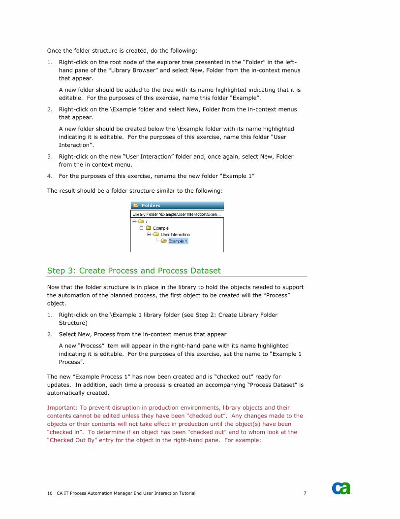
Once the folder structure is created, do the following:
1. Right-click on the root node of the explorer tree presented in the “Folder” in the left-
hand pane of the “Library Browser” and select New, Folder from the in-context menus
that appear.
A new folder should be added to the tree with its name highlighted indicating that it is
editable. For the purposes of this exercise, name this folder “Example”.
2. Right-click on the \Example folder and select New, Folder from the in-context menus
that appear.
A new folder should be created below the \Example folder with its name highlighted
indicating it is editable. For the purposes of this exercise, name this folder “User
Interaction”.
3. Right-click on the new “User Interaction” folder and, once again, select New, Folder
from the in context menu.
4. For the purposes of this exercise, rename the new folder “Example 1”
The result should be a folder structure similar to the following:
Step 3: Create Process and Process Dataset
Now that the folder structure is in place in the library to hold the objects needed to support
the automation of the planned process, the first object to be created will the “Process”
object.
1. Right-click on the \Example 1 library folder (see Step 2: Create Library Folder
Structure)
2. Select New, Process from the in-context menus that appear
A new “Process” item will appear in the right-hand pane with its name highlighted
indicating it is editable. For the purposes of this exercise, set the name to “Example 1
Process”.
The new “Example Process 1” has now been created and is “checked out” ready for
updates. In addition, each time a process is created an accompanying “Process Dataset” is
automatically created.
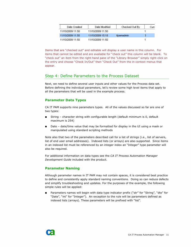
Important: To prevent disruption in production environments, library objects and their
contents cannot be edited unless they have been “checked out”. Any changes made to the
objects or their contents will not take effect in production until the object(s) have been
“checked in”. To determine if an object has been “checked out” and to whom look at the
“Checked Out By” entry for the object in the right-hand pane. For example:
CA IT Process Automation Manager 11
Items that are “checked out” and editable will display a user name in this column. For
items that cannot be edited and are available for “check out” this column will be blank. To
“check out” an item from the right-hand pane of the “Library Browser” simply right-click on
the entry and choose “Check In/Out” then “Check Out” from the in-context menus that
appear.
Step 4: Define Parameters to the Process Dataset
Next, we need to define several user inputs and other values for the Process data set.
Before defining the individual parameters, let’s review some high level items that apply to
all the parameters that will be used in the example process.
Parameter Data Types
CA IT PAM supports nine parameters types. All of the values discussed so far are one of
two types:
■ String – character string with configurable length (default minimum is 0, default
maximum is 254)
■ Date – date/time value that may be formatted for display in the UI using a mask or
manipulated using standard scripting methods
Note also that two of the parameters described call for a list of strings (i.e., list of servers,
list of end user email addresses). Indexed lists (or arrays) are also supported. Since items
in an indexed list must be referenced by an integer index an “Integer” type parameter will
also be required.
For additional information on data types see the CA IT Process Automation Manager
Development Guide included with the product.
Parameter Naming
Although parameter names in IT PAM may not contain spaces, it is considered best practice
to define and consistently apply standard naming conventions. Doing so can reduce defects
and simplify troubleshooting and updates. For the purposes of the example, the following
simple rules will be applied:
■ Parameters names will begin with data type indicator prefix (“str” for “String”, “dte” for
“Date”, “int” for “Integer”). An exception to the rule will be parameters defined as
indexed lists (arrays). These parameters will be prefixed with “list”.
12 CA IT Process Automation Manager End User Interaction Tutorial 7
■ Following the prefix will be a descriptive string in “camel” case. For example, the
parameter name for a string value representing a user name might be “strUserName”.
The rules themselves are not important. The key is that you agree on a set of rules and
apply them consistently.
Parameter Organization
Parameters can be organized in “Pages” within a dataset. Unlike parameters, Page names
may contain spaces and should be description of the contents. Grouping parameters
logically in Pages will simplify editing and troubleshooting efforts especially when a large
number of parameters are required. In the current example, Pages aligned with the key
operations described in the process outline (see Step 1: Planning) will be added and
parameters associated with those key operations will be grouped into those Pages.
Parameter Definition
Begin defining the parameters needed for each key operation described in the process
outline (see Step 1: Planning) applying the parameter naming convention and parameter
organization guidelines described earlier.
1. Open the CA IT PAM client interface and “Library Browser” for the test environment
(see Before You Begin)
2. Navigate to and select the “Example 1” folder in the explorer tree presented in the
“Folder” palette in the left-hand pane (see Step 2: Create Library Folder Structure)
3. Verify that the “Example 1 Process” entry in the right-hand pane is checked out and
available for editing (see Step 3: Create Process and Process Dataset)
4. Right-click on the “Example 1 Process” entry and select Edit from the in-context menu
that appears (or simply double-click the entry)
At this point a process definition panel will be displayed. You may be familiar with the
panel if you had completed the exercise to create the “Hello World” process covered in the
ITPAM Quick Start Guide (see Before You Begin). For the current example, before adding
operators to the process we will, instead, define parameters and set initial values in the
“Process” (or “Local”) dataset. To begin, select the “Dataset” palette in the left-hand pane
of the “Example 1 Process” process design panel.
Create Parameters for Start Request Operation
Start by adding a new Page to the dataset:
1. Right-click on the “Parameters” node in the “Dataset” palette
2. Select Add Page from the in-context menu that appears
3. Right-click on the new page node that is added
4. Select Rename from the in-context menu that appears
5. For the purposes of the example set the name to “Start Request” then press Enter to
complete the procedure
The operation description calls for two parameters:
CA IT Process Automation Manager 13
■ strServer – String type parameter which identifies the name of the server the user
would like to take offline for maintenance
■ dteMaintenanceDate – Date type parameter which identifies the date the user would
like to take the server offline for maintenance
Create Parameter strServer
To create a new parameter “strServer” do the following:
1. Right-click on the “Start Request” page node
2. Select Add Parameter from the in-context menu that appears
3. Right-click on the new parameter node that was added
4. Select Rename from the in-context menu that appears
5. Set the parameter name to “strServer”
Set Properties for Parameter strServer
To set the basic properties for the new parameter “strServer” do the following:
1. Select the node for the parameter in the explorer tree in the left-hand to display the
parameter properties panel in the right-hand pane
2. Choose “String” from the “Type” drop-down list at the top of the parameters properties
panel
3. In the “General” section the value for “Page” should already be set to “Start Request”
4. Set the description to “Server to be taken offline for maintenance”
Do not set a “Default Value”.
5. Set the “Current Value” to “SERVER01”
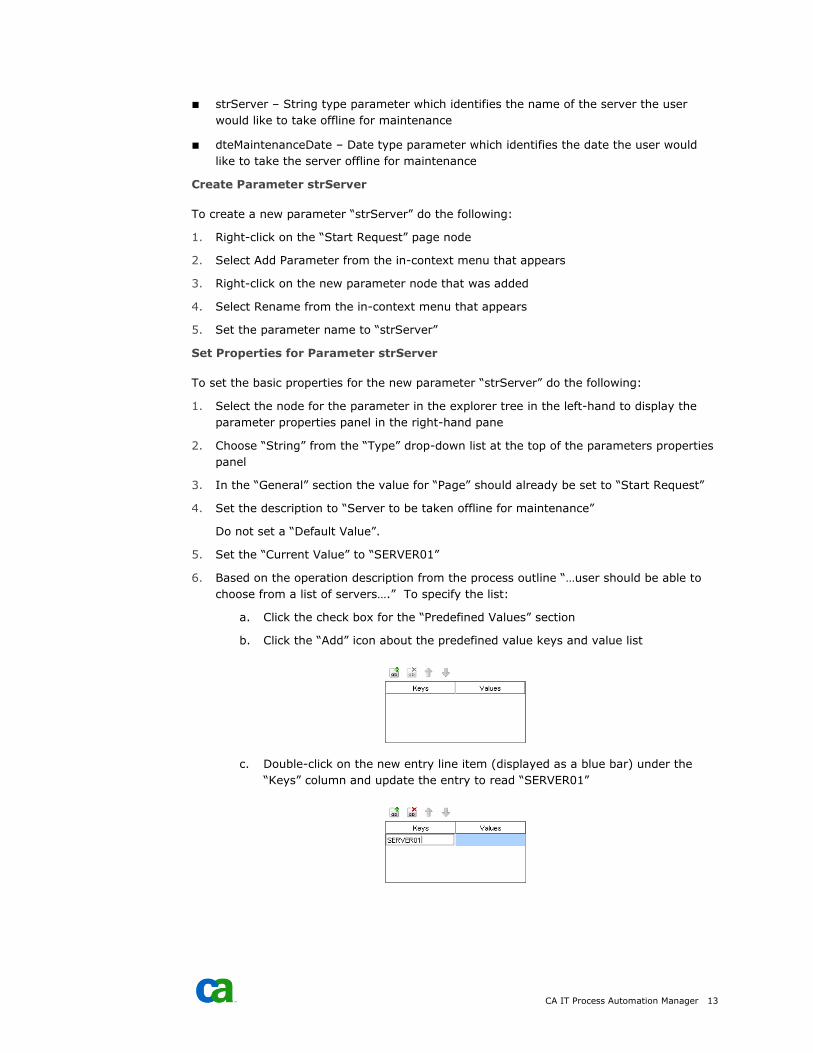
6. Based on the operation description from the process outline “…user should be able to
choose from a list of servers….” To specify the list:
a. Click the check box for the “Predefined Values” section
b. Click the “Add” icon about the predefined value keys and value list
c. Double-click on the new entry line item (displayed as a blue bar) under the
“Keys” column and update the entry to read “SERVER01”
14 CA IT Process Automation Manager End User Interaction Tutorial 7
d. Press “Enter”
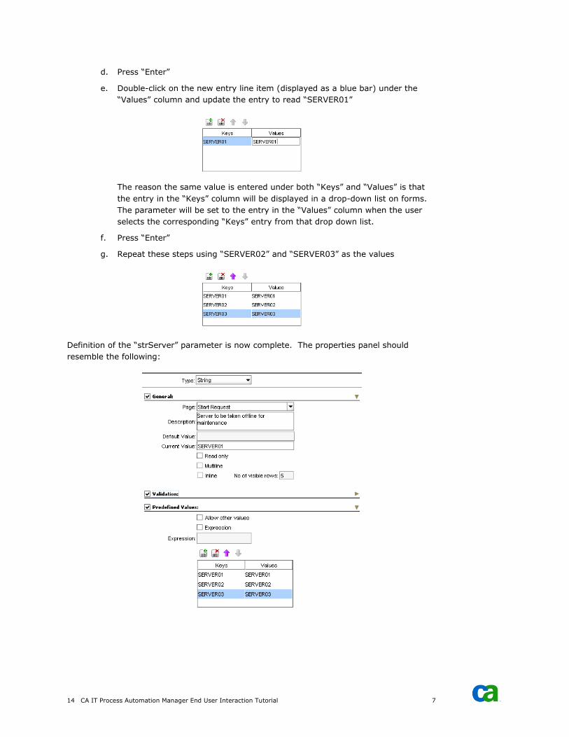
e. Double-click on the new entry line item (displayed as a blue bar) under the
“Values” column and update the entry to read “SERVER01”
The reason the same value is entered under both “Keys” and “Values” is that
the entry in the “Keys” column will be displayed in a drop-down list on forms.
The parameter will be set to the entry in the “Values” column when the user
selects the corresponding “Keys” entry from that drop down list.
f. Press “Enter”
g. Repeat these steps using “SERVER02” and “SERVER03” as the values
Definition of the “strServer” parameter is now complete. The properties panel should
resemble the following:
CA IT Process Automation Manager 15
Select File, Save from the menu or click the “Save” icon (diskette) on the toolbar to save
the changes.
Create Parameter dteMaintenanceDate
To create a new parameter “dteMaintenanceDate” do the following:
1. Right-click on the “Start Request” page node
2. Select Add Parameter from the in-context menu that appears
3. Right-click on the new parameter node that was added
4. Select Rename from the in-context menu that appears
5. Set the parameter name to “dteMaintenanceDate”
Set Properties for Parameter dteMaintenanceDate
To set the basic properties for the new parameter “dteMaintenanceDate” do the following:
1. Select the node for the parameter in the explorer tree in the left-hand to display the
parameter properties panel in the right-hand pane
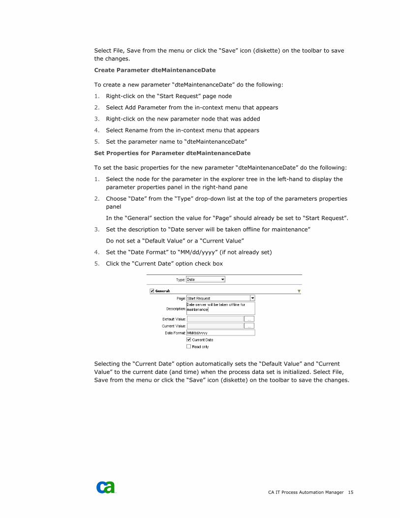
2. Choose “Date” from the “Type” drop-down list at the top of the parameters properties
panel
In the “General” section the value for “Page” should already be set to “Start Request”.
3. Set the description to “Date server will be taken offline for maintenance”
Do not set a “Default Value” or a “Current Value”
4. Set the “Date Format” to “MM/dd/yyyy” (if not already set)
5. Click the “Current Date” option check box
Selecting the “Current Date” option automatically sets the “Default Value” and “Current
Value” to the current date (and time) when the process data set is initialized. Select File,
Save from the menu or click the “Save” icon (diskette) on the toolbar to save the changes.
16 CA IT Process Automation Manager End User Interaction Tutorial 7
Create Parameters for Approver Alert Operation
Begin by adding a new “Page” to the dataset. To do this:
1. Right-click on any node in the “Dataset” palette
2. Select “Add Page” from the in-context menu that appears
3. Right-click on the new page node that was added
4. Select “Rename” from the in-context menu that appears
5. Set the name to “Approver Alert”
Based on the operation description, the following parameters are required:
■ strApproverEmail – String type parameter which identifies the email address for the
designated process approver
■ strApproverSubject – String type parameter which identifies the subject line content
for the email alert sent to the approver
■ strApproverMessage – String type parameter which identifies the message body
content to be sent in the email alert sent to the approver
Create Parameter strApproverEmail
To create a new parameter “strApproverEmail” do the following:
1. Right-click on the “Approver Alert” page node
2. Select “Add Parameter” from the in-context menu that appears
3. Right-click on the new parameter node that was added
4. Select “Rename” from the in-context menu that appears
5. Set the parameter name to “strApproverEmail”
Set Properties for Parameter strApproverEmail
To set the properties for the new parameter “strApproverEmail” do the following:
1. Select the node for the parameter.
A corresponding parameter properties panel should appear in the right-hand pane.
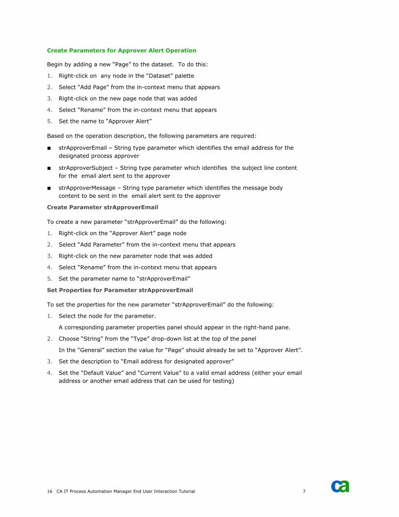
2. Choose “String” from the “Type” drop-down list at the top of the panel
In the “General” section the value for “Page” should already be set to “Approver Alert”.
3. Set the description to “Email address for designated approver”
4. Set the “Default Value” and “Current Value” to a valid email address (either your email
address or another email address that can be used for testing)
CA IT Process Automation Manager 17
Select File, Save from the menu or click the “Save” icon (diskette) on the toolbar to save
the changes.
Create Parameter strApproverSubject
To create the new parameter “strApproverSubject” do the following:
1. Right-click on the “Approver Alert” page node
2. Select “Add Parameter” from the in-context menu that appears
3. Right-click on the new parameter node that was added
4. Select “Rename” from the in-context menu that appears
5. Set the parameter name to “strApproverSubject”
Set Properties for Parameter strApproverSubject
To set the properties for the new parameter “strApproverSubject” do the following:
1. Select the node for the parameter.
A corresponding parameter properties panel should appear in the right-hand pane.
2. Choose “String” from the “Type” drop-down list at the top of the panel
In the “General” section the value for “Page” should already be set to “Approver Alert”.
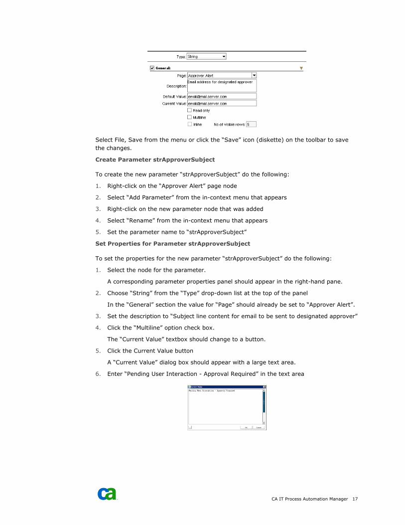
3. Set the description to “Subject line content for email to be sent to designated approver”
4. Click the “Multiline” option check box.
The “Current Value” textbox should change to a button.
5. Click the Current Value button
A “Current Value” dialog box should appear with a large text area.
6. Enter “Pending User Interaction - Approval Required” in the text area
18 CA IT Process Automation Manager End User Interaction Tutorial 7
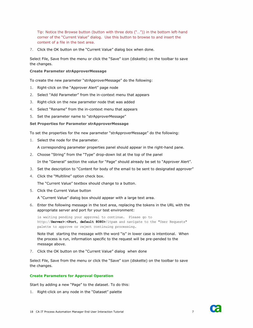
Tip: Notice the Browse button (button with three dots (“…”)) in the bottom left-hand
corner of the “Current Value” dialog. Use this button to browse to and insert the
content of a file in the text area.
7. Click the OK button on the “Current Value” dialog box when done.
Select File, Save from the menu or click the “Save” icon (diskette) on the toolbar to save
the changes.
Create Parameter strApproverMessage
To create the new parameter “strApproverMessage” do the following:
1. Right-click on the “Approver Alert” page node
2. Select “Add Parameter” from the in-context menu that appears
3. Right-click on the new parameter node that was added
4. Select “Rename” from the in-context menu that appears
5. Set the parameter name to “strApproverMessage”
Set Properties for Parameter strApproverMessage
To set the properties for the new parameter “strApproverMessage” do the following:
1. Select the node for the parameter.
A corresponding parameter properties panel should appear in the right-hand pane.
2. Choose “String” from the “Type” drop-down list at the top of the panel
In the “General” section the value for “Page” should already be set to “Approver Alert”.
3. Set the description to “Content for body of the email to be sent to designated approver”
4. Click the “Multiline” option check box.
The “Current Value” textbox should change to a button.
5. Click the Current Value button
A “Current Value” dialog box should appear with a large text area.
6. Enter the following message in the text area, replacing the tokens in the URL with the
appropriate server and port for your test environment:
is waiting pending your approval to continue. Please go to
http://Server>:<Port, default 8080>/itpam and navigate to the "User Requests"
palette to approve or reject continuing processing.
Note that starting the message with the word “is” in lower case is intentional. When
the process is run, information specific to the request will be pre-pended to the
message above.
7. Click the OK button on the “Current Value” dialog when done
Select File, Save from the menu or click the “Save” icon (diskette) on the toolbar to save
the changes.
Create Parameters for Approval Operation
Start by adding a new “Page” to the dataset. To do this:
1. Right-click on any node in the “Dataset” palette
CA IT Process Automation Manager 19
2. Select “Add Page” from the in-context menu that appears
3. Right-click on the new page node that was added
4. Select Rename from the in-context menu that appears
5. Set the name to “Approval”
Based on the description of the operation in the process outline, it would seem that no
parameters are required. However, the operation does indicate that a form will be
generated for the approver to use to either approve or reject the request. Interactive user
forms support entries for both a title and description properties. Both properties accept a
string or a reference to “String” type parameter.
Create Parameter strApprovalFormTitle
To create the new parameter “strApprovalFormTitle” do the following:
1. Right-click on the “Approval” page node
2. Select “Add Parameter” from the in-context menu that appears
3. Right-click on the new parameter node that is added
4. Select Rename from the in-context menu that appears
5. Set the parameter name to “strApprovalFormTitle”
Set Properties for Parameter strApprovalFormTitle
To set properties for the new parameter “strApprovalFormTitle” do the following:
1. Select the node for the parameter.
A corresponding parameter properties panel should appear in the right-hand pane.
2. Choose “String” from the “Type” drop-down list at the top of the panel
In the “General” section the value for “Page” should already be set to “Approval”.
3. Set the description to “Approval form title”
4. Set the “Current Value” to “Request for Approval to Take Server Offline”
Select File, Save from the menu or click the “Save” icon (diskette) on the toolbar to save
the changes.
Create Parameter strApprovalFormDescription
To create the new parameter “strApprovalFormDescription” do the following:
1. Right-click on the “Approval” page node
2. Select “Add Parameter” from the in-context menu that appears
3. Right-click on the new parameter node that was added
4. Select “Rename” from the in-context menu that appears
5. Set the parameter name to “strApprovalFormDescription”
20 CA IT Process Automation Manager End User Interaction Tutorial 7
Set Properties for Parameter strApprovalFormDescription
To set properties for the new parameter “strApprovalFormDescription” do the following:
1. Select the node for the parameter.
A corresponding parameter properties panel should appear in the right-hand pane.
2. Choose “String” from the “Type” drop-down list at the top of the panel
In the “General” section the value for “Page” should already be set to “Approval”.
3. Set the description to “Approval form description”
4. Set the “Current Value” to “Request to take a server offline for maintenance is pending
approval.”
Select File, Save from the menu or click the “Save” icon (diskette) on the toolbar to save
the changes.
Create Parameters for End User Alert Operation
Start by adding a new “Page” to the dataset. To do this:
1. Right-click on any node in the “Dataset” palette
2. Select “Add Page” from the in-context menu that appears
3. Right-click on the new page node that was added
4. Select Rename from the in-context menu that appears
5. Set the name to “End User Alert”
The following parameters were included in the process outline for the operation:
■ listEndUserEmail – Indexed list (array) of end user email address strings to be notified
if the request to take the server offline is approved
■ intEndUserListIndex – Integer type parameter used to iterate the end user email list
■ strEndUserSubject –String type parameter which identifies the subject line content of
the email alert sent to the end users
■ strEndUserMessage – String type parameter which identifies the message body
content to included in the email alert sent to the end users
■ strMaintenanceDate – String type parameter which identifies the date the server is to
be offline expressed in a format appropriate for an email message
Create Parameter listEndUserEmail
To create a new parameter “listEndUserEmail” do the following:
1. Right-click on the “End User Alert” page node
2. Select “Add Parameter” from the in-context menu that appears
3. Right-click on the new parameter node that was added
4. Select Rename from the in-context menu that appears
5. Set the parameter name to “listEndUserEmail”
CA IT Process Automation Manager 21
Set Properties for Parameter listEndUserEmail
To set the basic properties for the new parameter “listEndUserEmail” do the following:
1. Select the node for the parameter.
A corresponding parameter properties panel should appear in the right-hand pane.
2. Choose “String” from the “Type” drop-down list at the top of the panel
In the “General” section, the value for “Page” should already be set to “End User Alert”.
3. Set the description to “List of end user email addresses to be notified”
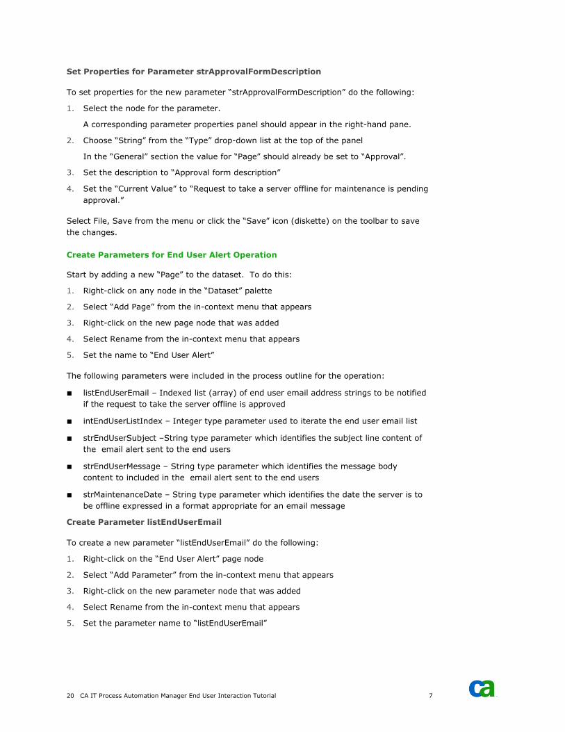
Define the indexed list of end user email addresses as follows:
1. On the parameter properties panel click the “Indexed” check box
2. Click the “Add” icon in the “Values” section
An entry box appears.
3. Enter an end user email address in the entry box and click Enter to complete the
update:
4. Repeat step 3 for any additional email addresses that will be used for testing.
Select File, Save from the menu or click the “Save” icon (diskette) on the toolbar to save
the changes.
Create Parameter intEndUserListIndex
To create a new parameter “intEndUserListIndex” do the following:
1. Right-click on the “End User Alert” page node
2. Select Add Parameter from the in-context menu that appears
3. Right-click on the new parameter node that was added
4. Select Rename from the in-context menu that appears
5. Set parameter name to “intEndUserListIndex”

22 CA IT Process Automation Manager End User Interaction Tutorial 7
Set Properties for Parameter intEndUserListIndex
To ser the properties for the new parameter do the following:
1. Select the node for the parameter.
A corresponding parameter properties panel should appear in the right-hand pane.
2. Choose “Integer” from the “Type” drop-down list at the top of the panel
In the “General” section the value for “Page” should already be set to “End User Alert”.
3. Set the description to “Integer parameter to iterate end user email list”
4. Set both the “Default Value” and “Current Value” to 0.
Select File, Save from the menu or click the “Save” icon (diskette) on the toolbar to save
the changes.
Create Parameter strEndUserSubject
To create the new parameter “strEndUserSubject” do the following:
1. Right-click on the “End User Alert” page node
2. Select Add Parameter from the in-context menu that appears
3. Right-click on the new parameter node that was added
4. Select “Rename” from the in-context menu that appears
5. Set the parameter name to “strEndUserSubject”
Set Properties for Parameter strEndUserSubject
To set the properties for the new parameter “strEndUserSubject” do the following:
1. Select the node for the parameter.
A corresponding parameter properties panel should appear in the right-hand pane.
2. Choose “String” from the “Type” drop-down list at the top of the panel
In the “General” section the value for “Page” should already be set to “End User Alert”.
3. Set the description to “Subject line content for email to be sent to end user”
4. Click the “Multiline” option check box.
The “Current Value” textbox should change to a button.
5. Click the Current Value button.
A “Current Value” dialog box should appear with a large text area.
6. Enter “Notice of Scheduled Maintenance:” in the text area and click OK.
Select File, Save from the menu or click the “Save” icon (diskette) on the toolbar to save
the changes.
CA IT Process Automation Manager 23
Create Parameter strEndUserMessage
To create the new parameter “strEndUserMessage” do the following:
1. Right-click on the “End User Alert” page node
2. Select Add Parameter from the in-context menu that appears
3. Right-click on the new parameter node that is added
4. Select Rename from the in-context menu that appears
5. Set the parameter name to “strEndUserMessage”
Set Properties for Parameter strEndUserMessage
To set the properties for the new parameter “strEndUserMessage” do the following:
1. Select the node for the parameter.
A corresponding parameter properties panel should appear in the right-hand pane
2. Choose “String” from the “Type” drop-down list at the top of the panel
In the “General” section the value for “Page” should already be set to “End User Alert”.
3. Set the description to “Message content for email to be sent to end users”
4. Click the “Multiline” option check box.
The “Current Value” textbox should change to a button.
5. Click the “Current Value” button.
A “Current Value” dialog box should appear with a large text area.
6. Enter the following message in the text area:
will be offline for maintenance. We apologize for any inconvenience.
This message was generated for testing purpose only.
Note that starting the word “will” in lower case is intentional. When the process is run,
information specific to the request will be pre-pended to the message text.
7. Click the OK button on the “Current Value” dialog when done
Select File, Save from the menu or click the “Save” icon (diskette) on the toolbar to save
the changes.
Create Parameter strMaintenanceDate
To create the new parameter “strMaintenanceDate” do the following:
1. Right-click on the “End User Alert” page node
2. Select Add Parameter from the in-context menu that appears
3. Right-click on the new parameter node that is added
4. Select Rename from the in-context menu that appears
5. Set the parameter name to “strMaintenanceDate”
24 CA IT Process Automation Manager End User Interaction Tutorial 7
Set Properties for Parameter strMaintenanceDate
To set the properties for the new parameter “strMaintenanceDate” do the following:
1. Select the node for the parameter.
A corresponding parameter properties panel should appear in the right-hand pane.
2. Choose “String” from the “Type” drop-down list at the top of the panel
In the “General” section the value for “Page” should already be set to “End User Alert”.
Select File, Save from the menu or click the “Save” icon (diskette) on the toolbar to save
the changes.
Check In Updated Process
Now that all the required parameters described in the process outline have been created
and their properties set the final step is to check in the updated process and its data set.
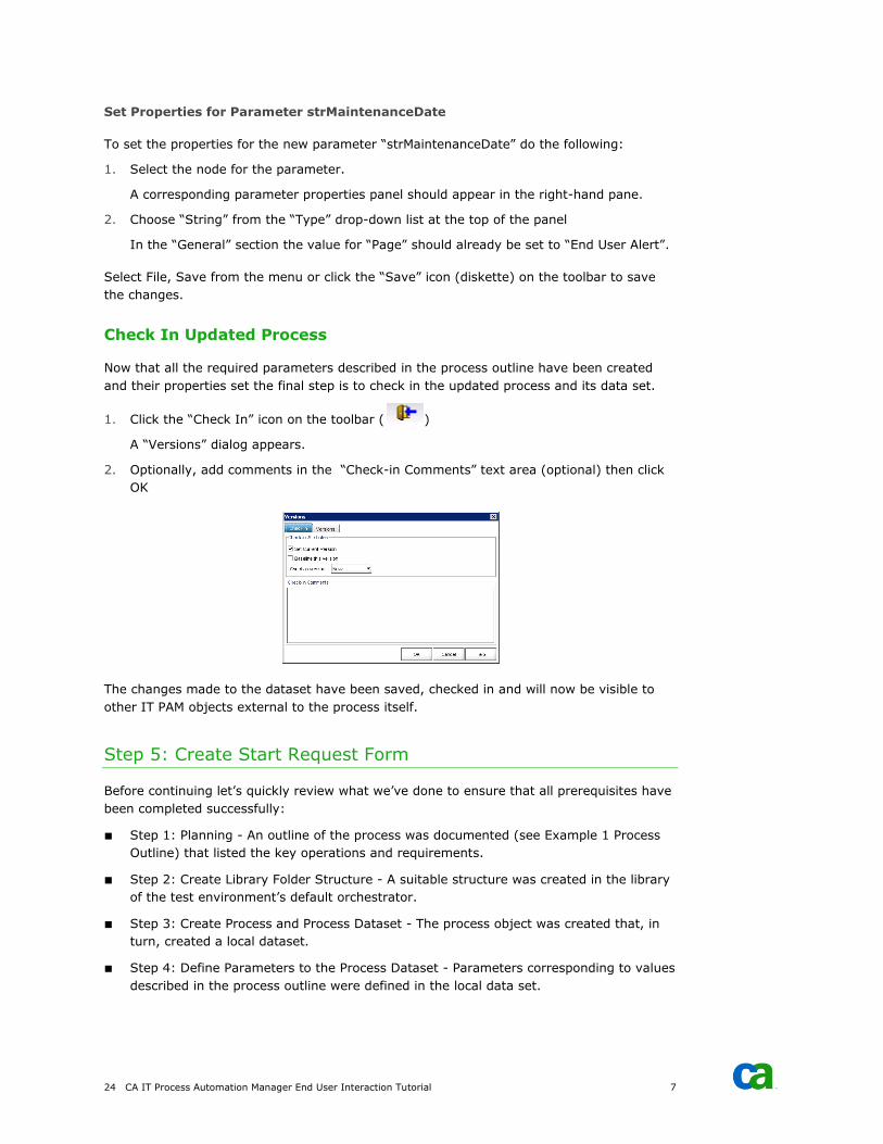
1. Click the “Check In” icon on the toolbar ( )
A “Versions” dialog appears.
2. Optionally, add comments in the “Check-in Comments” text area (optional) then click
OK
The changes made to the dataset have been saved, checked in and will now be visible to
other IT PAM objects external to the process itself.
Step 5: Create Start Request Form
Before continuing let’s quickly review what we’ve done to ensure that all prerequisites have
been completed successfully:
■ Step 1: Planning - An outline of the process was documented (see Example 1 Process
Outline) that listed the key operations and requirements.
■ Step 2: Create Library Folder Structure - A suitable structure was created in the library
of the test environment’s default orchestrator.
■ Step 3: Create Process and Process Dataset - The process object was created that, in
turn, created a local dataset.
■ Step 4: Define Parameters to the Process Dataset - Parameters corresponding to values
described in the process outline were defined in the local data set.
CA IT Process Automation Manager 25
With the prerequisite steps completed, the next step is to create the “Start Request” form
required by the first operation in the planned process outline. From the brief description in
the process outline it should be clear that the user should be able to pick the server name
they intend to take offline for maintenance from a predefined list and specify the date.
Create the Start Request Form
To create the new “Start Request Form” object do the following:
1. Open the CA IT PAM client interface and “Library Browser” for the test environment
(see Before You Begin)
2. Navigate to and select the \Example 1 folder in the explorer tree presented in the
“Folder” palette in the left-hand pane (see Step 2: Create Library Folder Structure)
3. Right-click on the \Example 1 folder and select New Object, Start Request Form from
the in-context menus that appear
A new entry should appear in the right-pane with the default name highlighted
indicating it is editable.
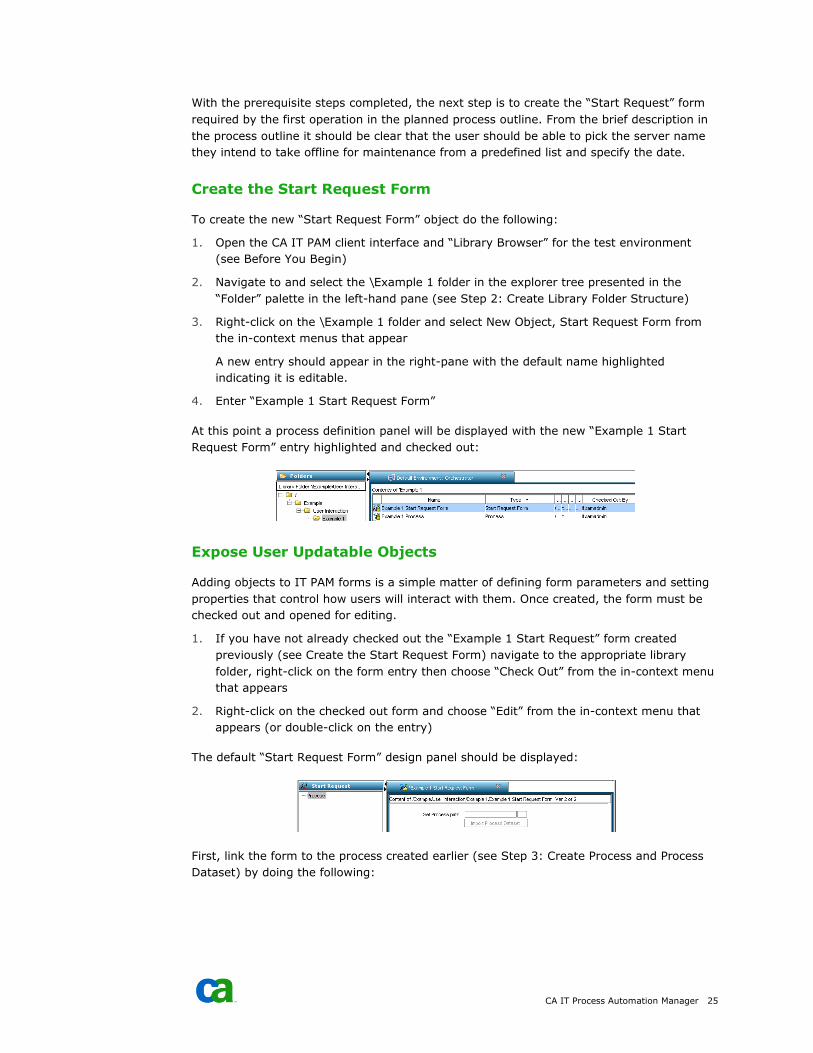
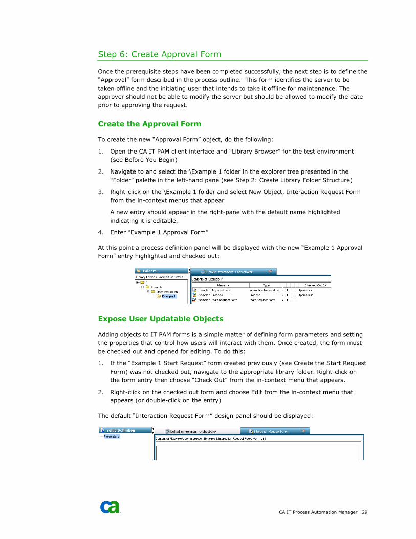
4. Enter “Example 1 Start Request Form”
At this point a process definition panel will be displayed with the new “Example 1 Start
Request Form” entry highlighted and checked out:
Expose User Updatable Objects
Adding objects to IT PAM forms is a simple matter of defining form parameters and setting
properties that control how users will interact with them. Once created, the form must be
checked out and opened for editing.
1. If you have not already checked out the “Example 1 Start Request” form created
previously (see Create the Start Request Form) navigate to the appropriate library
folder, right-click on the form entry then choose “Check Out” from the in-context menu
that appears
2. Right-click on the checked out form and choose “Edit” from the in-context menu that
appears (or double-click on the entry)
The default “Start Request Form” design panel should be displayed:
First, link the form to the process created earlier (see Step 3: Create Process and Process
Dataset) by doing the following:
26 CA IT Process Automation Manager End User Interaction Tutorial 7
1. In “Start Request” palette in the left hand pane of the form design panel click the
“Process” node in the explorer tree
2. In the right-hand click the browse button (a button with three dots (“…”) to the right of
the “Set Process path” textbox)
3. Using the explorer tree on the “Object Browser” dialog box that appears, navigate to
and select the “Example 1 Process”, then click the OK button.
The “Set Process path” textbox should indicate the path to the process, linking the form to
the process.
Next, the parameters for the required user entries (“Server” and “Maintenance Date”) must
be added. We could use the “Start Request” palette in the left-hand pane to add pages and
parameters just as we did when we updated the process dataset (see Step 4: Define
Parameters to the Process Dataset). However, once a “Start Request Form” is associated
with a process, IT PAM allows us to import the process dataset parameters definitions by
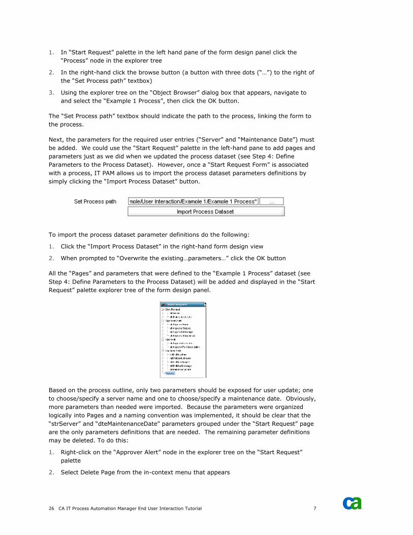
simply clicking the “Import Process Dataset” button.
To import the process dataset parameter definitions do the following:
1. Click the “Import Process Dataset” in the right-hand form design view
2. When prompted to “Overwrite the existing…parameters…” click the OK button
All the “Pages” and parameters that were defined to the “Example 1 Process” dataset (see
Step 4: Define Parameters to the Process Dataset) will be added and displayed in the “Start
Request” palette explorer tree of the form design panel.
Based on the process outline, only two parameters should be exposed for user update; one
to choose/specify a server name and one to choose/specify a maintenance date. Obviously,
more parameters than needed were imported. Because the parameters were organized
logically into Pages and a naming convention was implemented, it should be clear that the
“strServer” and “dteMaintenanceDate” parameters grouped under the “Start Request” page
are the only parameters definitions that are needed. The remaining parameter definitions
may be deleted. To do this:
1. Right-click on the “Approver Alert” node in the explorer tree on the “Start Request”
palette
2. Select Delete Page from the in-context menu that appears
CA IT Process Automation Manager 27
3. When prompted, confirm the deletion request by clicking the OK button
4. Repeat steps 1 through 3 for the “Approval” and “End User Alert” pages
Next, edit the remaining two parameters as follows:
1. Click on the “strServer” parameter node in the explorer tree.
The properties panel for the parameter will be displayed in the right-pane and an
additional “Label” property will be exposed in the “General” section.
2. Set the “Label” property to “Select Server”.
3. Click on the “dteMaintenanceDate” parameter node in the explorer tree.
The properties for the parameter will be displayed in the right-pane.
4. Set the “Label” to “Select Maintenance Date”
Select File, Save from the menu or click the “Save” icon (diskette) on the toolbar to save
the changes.
Changes made to the “Start Request” parameters – including deletions - do not impacted
the related process data set since the “Import Process Dataset” procedure imports only the
parameters definitions to the “Start Request”. The parameters are not directly linked.
However, later you will see that, because the parameter names match, changes to the
values of the parameters on the “Start Request” will change the value of a parameter with
the same name in the process dataset.
Since only two parameters are used on the “Start Request” form why not just create two
parameters rather import all the parameters from the process dataset? Defining the
parameters in the process data set, then importing the definitions, reduces the potential for
error. As you will see later, if the parameter names on the “Start Request” and the
parameter names in the process dataset match, the values in the process data set will be
automatically updated by a user on the “Start Request” form. As you will see next, because
we took the time to properly define and set the properties of the parameters in the process
data set, we are done editing and are ready to test the “Start Request” form.
Test the Start Request Form
Now you are ready to test the “Start Request” form. To do this:
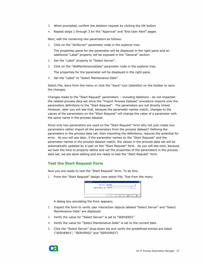
1. From the “Start Request” design view select File, Test from the menu
A dialog box emulating the from appears;
2. Inspect the form to verify user interaction objects labeled “Select Server” and “Select
Maintenance Date” are displayed
3. Verify the value for “Select Server” is set to “SERVER01”
4. Verify the value for “Select Maintenance Date” is set to the current date
5. Click the “Select Server” drop-down list and verify the predefined entries are listed
(“SERVER01”, “SERVER02” and “SERVER03”)
28 CA IT Process Automation Manager End User Interaction Tutorial 7
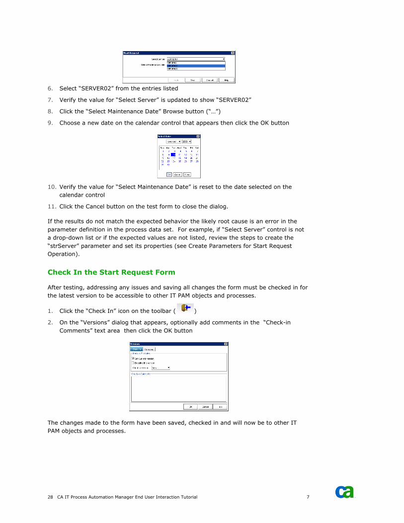
6. Select “SERVER02” from the entries listed
7. Verify the value for “Select Server” is updated to show “SERVER02”
8. Click the “Select Maintenance Date” Browse button (“…”)
9. Choose a new date on the calendar control that appears then click the OK button
10. Verify the value for “Select Maintenance Date” is reset to the date selected on the
calendar control
11. Click the Cancel button on the test form to close the dialog.
If the results do not match the expected behavior the likely root cause is an error in the
parameter definition in the process data set. For example, if “Select Server” control is not
a drop-down list or if the expected values are not listed, review the steps to create the
“strServer” parameter and set its properties (see Create Parameters for Start Request
Operation).
Check In the Start Request Form
After testing, addressing any issues and saving all changes the form must be checked in for
the latest version to be accessible to other IT PAM objects and processes.
1. Click the “Check In” icon on the toolbar ( )
2. On the “Versions” dialog that appears, optionally add comments in the “Check-in
Comments” text area then click the OK button
The changes made to the form have been saved, checked in and will now be to other IT
PAM objects and processes.
CA IT Process Automation Manager 29
Step 6: Create Approval Form
Once the prerequisite steps have been completed successfully, the next step is to define the
“Approval” form described in the process outline. This form identifies the server to be
taken offline and the initiating user that intends to take it offline for maintenance. The
approver should not be able to modify the server but should be allowed to modify the date
prior to approving the request.
Create the Approval Form
To create the new “Approval Form” object, do the following:
1. Open the CA IT PAM client interface and “Library Browser” for the test environment
(see Before You Begin)
2. Navigate to and select the \Example 1 folder in the explorer tree presented in the
“Folder” palette in the left-hand pane (see Step 2: Create Library Folder Structure)
3. Right-click on the \Example 1 folder and select New Object, Interaction Request Form
from the in-context menus that appear
A new entry should appear in the right-pane with the default name highlighted
indicating it is editable.
4. Enter “Example 1 Approval Form”
At this point a process definition panel will be displayed with the new “Example 1 Approval
Form” entry highlighted and checked out:
Expose User Updatable Objects
Adding objects to IT PAM forms is a simple matter of defining form parameters and setting
the properties that control how users will interact with them. Once created, the form must
be checked out and opened for editing. To do this:
1. If the “Example 1 Start Request” form created previously (see Create the Start Request
Form) was not checked out, navigate to the appropriate library folder. Right-click on
the form entry then choose “Check Out” from the in-context menu that appears.
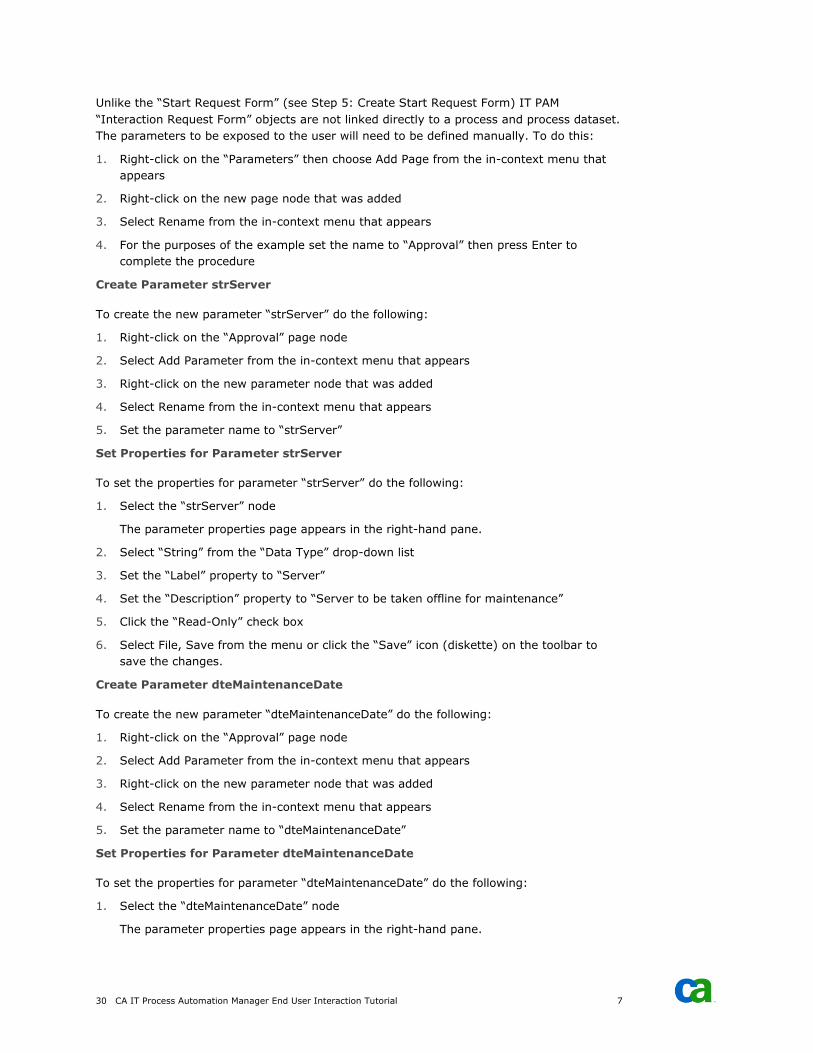
2. Right-click on the checked out form and choose Edit from the in-context menu that
appears (or double-click on the entry)
The default “Interaction Request Form” design panel should be displayed:
30 CA IT Process Automation Manager End User Interaction Tutorial 7
Unlike the “Start Request Form” (see Step 5: Create Start Request Form) IT PAM
“Interaction Request Form” objects are not linked directly to a process and process dataset.
The parameters to be exposed to the user will need to be defined manually. To do this:
1. Right-click on the “Parameters” then choose Add Page from the in-context menu that
appears
2. Right-click on the new page node that was added
3. Select Rename from the in-context menu that appears
4. For the purposes of the example set the name to “Approval” then press Enter to
complete the procedure
Create Parameter strServer
To create the new parameter “strServer” do the following:
1. Right-click on the “Approval” page node
2. Select Add Parameter from the in-context menu that appears
3. Right-click on the new parameter node that was added
4. Select Rename from the in-context menu that appears
5. Set the parameter name to “strServer”
Set Properties for Parameter strServer
To set the properties for parameter “strServer” do the following:
1. Select the “strServer” node
The parameter properties page appears in the right-hand pane.
2. Select “String” from the “Data Type” drop-down list
3. Set the “Label” property to “Server”
4. Set the “Description” property to “Server to be taken offline for maintenance”
5. Click the “Read-Only” check box
6. Select File, Save from the menu or click the “Save” icon (diskette) on the toolbar to
save the changes.
Create Parameter dteMaintenanceDate
To create the new parameter “dteMaintenanceDate” do the following:
1. Right-click on the “Approval” page node
2. Select Add Parameter from the in-context menu that appears
3. Right-click on the new parameter node that was added
4. Select Rename from the in-context menu that appears
5. Set the parameter name to “dteMaintenanceDate”
Set Properties for Parameter dteMaintenanceDate
To set the properties for parameter “dteMaintenanceDate” do the following:
1. Select the “dteMaintenanceDate” node
The parameter properties page appears in the right-hand pane.
CA IT Process Automation Manager 31
2. Select “Date” from the “Data Type” drop-down list
3. Set the “Label” property to “Maintenance Date”
4. Set the “Description” property to “Date server will be taken offline for maintenance”
5. Verify the “Date Format” property is set to “MM/dd/yyyy”
Select File, Save from the menu or click the “Save” icon (diskette) on the toolbar to save
the changes.
Test the Approval Form
Assuming the steps to create (see Create the Approval Form) and add the user updatable
parameters (see Expose User Updatable Objects) you are ready to test the “Approval” form.
To do this:
1. From the design view select File, Test from the menu
A dialog box emulating the form appears.
2. Inspect the form to verify user interaction objects labeled “Server” and “Maintenance
Date” are displayed
3. Click the Cancel button to close the dialog
No values will be set or displayed for “Server” or “Maintenance Date” since they are set by
the user initiating the request through the “Start Request Form” (see Step 5: Create Start
Request Form). The values displayed on the “Approval” form will be set programmatically
when the process-specific instance of the “Approval” is initialized.
Check In the Approval Form
Once you have tested the form and addressed any issues that arose, it is time to save the
changes and check the form back in. This enables the latest version to be accessed by other
IT PAM objects and processes. To do this:
1. Click the “Check In” icon on the toolbar ( )
The “Versions” dialog appears,
2. Add comments in the “Check-in Comments” text area (optional) then click the OK
button
The changes made to the form have been saved, checked in and will now be accessible to
other IT PAM objects and processes.
32 CA IT Process Automation Manager End User Interaction Tutorial 7
Step 7: Define the Process
To successfully add and set properties for operators that will be included in the process all
prerequisite should be completed:
■ Step 1: Planning - An outline of the process was documented (see Example 1 Process
Outline) that listed the key operations and requirements.
■ Step 2: Create Library Folder Structure - A suitable structure was created in the test
environment’s default orchestrator’s library
■ Step 3: Create Process and Process Dataset - The process object was created that in
turn creates local dataset.
■ Step 4: Define Parameters to the Process Dataset - Parameters corresponding to values
described in the process outline were defined in the local dataset.
■ Step 5: Create Start Request Form – Define a form for user to use to set parameter
values and start the process
■ Step 6: Create Approval Form – Define a form that allows the approver to modify the
maintenance date if necessary and approve the request
It is now time to define the process itself.
Prepare to Edit the Process
To initiate the edit process, begin by checking out the process and opening a process
designer panel. To do this:
1. Open the CA IT PAM client interface and “Library Browser” for the test environment
(see Before You Begin)
2. Navigate to and select the \Example 1 folder in the explorer tree presented in the
“Folder” palette in the left-hand pane (see Step 2: Create Library Folder Structure)
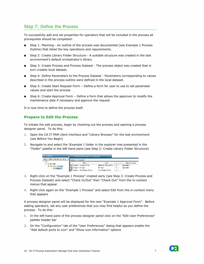
3. Right-click on the “Example 1 Process” created early (see Step 3: Create Process and
Process Dataset) and select “Check In/Out” then “Check Out” from the in-context
menus that appear
4. Right-click again on the “Example 1 Process” and select Edit from the in-context menu
that appears
A process designer panel will be displayed for the new “Example 1 Approval Form”. Before
adding operators, set any user preferences that you may find helpful as you define the
process. To do this:
1. In the left-hand pane of the process designer panel click on the “Edit User Preferences”
palette header bar
2. On the “Configuration” tab of the “User Preferences” dialog that appears enable the
“Add default ports to icon” and “Show icon information” options
CA IT Process Automation Manager 33
3. On the “Process” disable (uncheck) all but the following entries: Alert, Common,
Dataset, Interpreter Module and Workflow Module
4. On the “Palette Properties” tab set the value for “Number of visible palettes” to 5
5. Click the OK button to save the changes
Add Start and Stop Operators
The entry and exit points of the process will be defined using IT PAM “Start”, “Normal Stop”
and “Abnormal Stop” operators. To add these operators do the following:
1. In the left-hand pane of the process designer click on the “Common” palette header bar
2. Click on and drag the “Start” object icon from the palette to the right-hand main
process design window. For now, simply position it near the top of the panel.
3. Click on and drag the “Normal Stop” object icon from the palette to lower left part of
the main process design window
4. Click on and drag the “Abnormal Stop” object icon from the palette to the lower right
part of the main process design window
You can refine the layout later. Right now, let’s set properties for each of the newly added
operators, starting with the “Start” object. To do this:
1. Double-click on the “Start” object icon in the main process design panel
2. In the “Properties of…” panel that appears click on the “Information” header bar to
expand the section (if not already expanded)
3. In the “Icon” section set the “Name” property to “oprStart” (see Parameter Naming)
4. In the “Text” section disable the “Update automatically” option
5. Clear any content from the text area below the “Update automatically” option and enter
“Start process”
6. Click the Apply button at the bottom of the panel
Note that the comment “Start process” appears in the main panel of the process designer
panel. Comments will help document the process by clarifying the purpose of each
operator in the process and its intended behavior. Let’s do the same for the “Normal Stop”
operator. To do this:
1. Double-click on the “Normal Stop” icon in the main process design panel
2. In the “Properties of…” panel that appears click on the “Information” header bar
3. In the “Icon” section set the “Name” property to “oprNormalStop”
4. In the “Text” section disable the “Update automatically” option
5. Clear any content from the text area below the “Update automatically” option and enter
“Process completed successfully”
6. Click the Apply button at the bottom of the panel
Set similar properties for the “Abnormal Stop” operator by doing the following:
1. Double-click on the “Normal Stop” icon in the main process design panel
2. In the “Properties of…” panel that appears click on the “Information” header bar

34 CA IT Process Automation Manager End User Interaction Tutorial 7
3. In the “Icon” section set the “Name” property to “oprAbnormalStop”
4. In the “Text” section disable the “Update automatically” option
5. Clear any content from the text area below the “Update automatically” option and enter
“Process was aborted”
6. Click the Apply button at the bottom of the panel
Select File, Save from the menu or click the “Save” icon (diskette) on the toolbar to save
the changes.
Add Email Alert Operator to Notify Approver
According to the process outline (see Step 1: Planning) after the user starts the process the
approver should be notified via email. To do this we add an Email Alert operator by doing
the following:
1. In the left-hand pane of the process design panel click the “Alert Module” palette
header bar
2. Drag the “Email Alert” operator icon to the main process designer panel somewhere
below the “Start” operator
3. Double-click on the “Email Alert” operator icon in the main process designer panel
4. In the “Properties of…” panel that appears to the right click on the “Information” header
bar to expand the section
5. In the “Icon” section set the “Name” property to “oprEmailApprover”
6. Disable the “Update automatically” option in the “Text” section
7. Enter “Send an email notifying the approver that a request is pending” in the text area
provided below the “Update automatically” option
8. Click on the “Execution Settings” header bar
9. Enter “Orchestrator” in the “Touchpoint” property textbox
The operator to alert the approver has been added and the basic informational properties
have been set. You now need to set properties that will be used to generate the email itself
under the “Email” header of the “Properties of…” panel. To do this:
1. Click on the “Email” header bar to expand the section revealing the related properties
2. Enter the “itpamadmin” in quotes in the “*User Name” property textbox
Note: Values set for IT PAM properties can be set using literals (i.e., entering the value
directly) or using parameter values defined to a dataset. When a property label is
preceded by an asterisk (*) it indicates that the entry is expected to be a reference to a
parameter that must be evaluated and not a literal value. To set the property to a
literal value instead of a parameter reference, simply enclose the value in quotes.
3. Enter the password for the “itpamadmin” user enclosed in quotes in the “*Password”
property textbox
4. In the “*To” property textbox enter “Process.strApproverEmail” without quotes to
reference the parameter previous defined and set to the approver’s email address (see
Create Parameter strApproverEmail under Step 4: Define Parameters to the Process
Dataset)
CA IT Process Automation Manager 35
Note 1: Here the property label value is preceded by an asterisk (“*”) indicating that a
parameter reference is expected, by default. Enclose the entry in quotes only if it is to
be interpreted as a literal.
Note 2: Prepending “Process.” to the parameter indicates that the parameter instance
to be evaluated is the instance defined to the current process’s dataset. In our
example all the parameters used were defined to the default dataset created when the
process was added (see Step 3: Create Process and Process Dataset). As you continue
to work with IT PAM you will learn that additional datasets can be created external to
processes with parameters and values that can be accessed from multiple processes
and other objects.
5. Enter “Process.strApproverSubject” in the “*Subject” property textbox
6. Enter “Process.strApproverMessage” in the “*Message” property textbox
7. Click the Apply button at the bottom of the panel
Select File, Save from the menu or click the “Save” icon (diskette) on the toolbar to save
the changes.
Add User Interaction Operator to Link Approval Form
The process outline (see Step 1: Planning) states that, after being notified by email, the
approver confirmation process should continue using an approval form. The form itself was
defined earlier (see Step 6: Create Approval Form) but it has not been linked to the
process. To create the link and wait for the approver’s decision add a “User Interaction”
operator to the process by doing the following:
1. In the left-hand pane of the process design panel click the “Workflow” palette header
bar
2. Drag the “User Interaction” operator icon to the main process designer panel
somewhere below the “Start” operator
3. Double-click on the “User Interaction” operator icon in the main process designer panel
4. In the “Properties of…” panel that appears to the right click on the “Information” header
bar to expand the section
5. In the “Icon” section set the “Name” property to “oprApproval”
6. Disable the “Update automatically” option in the “Text” section
7. Enter “Suspend processing pending approval” in the text area provided below the
“Update automatically” option
8. Click on the “Execution Settings” header bar
9. Enter “Orchestrator” in the “Touchpoint” property textbox
With the basic information properties set, enter the “User Information” and “User Prompt”
parameter values by doing the following:
1. Click the “User Information” header bar
2. Click the Browse button (“…”) associated with the “*User” property
3. Use the explorer tree displayed on the “User” dialog that appears to select a user (for
the example, choose “itpamadmin”) then click the OK button on the dialog
4. Click the “User Prompt” header bar
36 CA IT Process Automation Manager End User Interaction Tutorial 7
5. Enter “Process.strApprovalFormTitle” in the “*Title” property textbox
6. Enter “Process.strApprovalFormDescription” in the “*Description” textbox
7. Click the Browse button (“…”) associated with the “*Interaction Request Form” property
8. Select “Example 1 Approval Form” (see Step 6: Create Approval Form) from the
explorer tree displayed on the “Object Browser” dialog then click the OK button to
close the dialog
The approval form is now associated with the process and the decision the approver makes
will be captured and used to continue or abort the process. However, remember that the
following two values specified by the user initiating the request should be displayed:
■ Name of server that will be taken offline for maintenance
■ Date server is requested to be taken offline for maintenance
Recall also that, because the form is an “Interaction Request Form” type, the form
parameters are not linked directly to any specific process and dataset. The values for the
two parameters to be displayed must be initialized prior to presenting the instance of the
form associated with the user request stored in the process dataset. To do this:
1. Click the “User Prompt” header bar if the section is not already displayed
2. Click the Browse button (“…”) associated with the “Form data initialization code:”
property
3. Enter the following two lines of code into the text area of the “Form data initialization
code” dialog that appears:
Form.strServer=Process.strServer;
Form.dteMaintenanceDate=Process.dteMaintenanceDate;
Note: Although the parameters were defined with the same name it is still necessary to
explicitly set the parameter values when initializing the form because the parameters
were defined to two different datasets (once in the process dataset and again in the
form dataset). Since the parameters are defined to and exist in two different contexts
the names represent two distinct entities. The qualifier “Process” indicates that the
parameter instance reference is to the instance associated with the current process
dataset. Likewise, the qualifier “Form” is used to specify that the instance reference is
to the instance of the parameter associated with the current form.
4. Click the OK button to close the dialog
5. Click the Apply button at the bottom of the panel
The settings to initialize the form properly have now been entered. But recall that, while
the parameter for the server name was defined as read-only, the process outline stipulated
that the approver should be able to change the date the server will be taken offline for
maintenance. Once again, even though the form parameter and process parameter share
the same name, they separate instances defined to two different datasets. The process
instance of the parameter “dteMaintenanceDate” must be set to the current value of the
form/operator instance of the parameter “dteMaintenanceDate” since the approver may
have change the value. To do this:
1. Click the “Execution” settings header bar
2. Click the “Post Execution Code” link in the “Processing” section
3. Enter the following line in the text area of the “Post-execution” dialog that appears:
CA IT Process Automation Manager 37
Process.dteMaintenanceDate = oprApproval.dteMaintenanceDate;
4. Click the OK button to close the “Post-execution” dialog
5. Click the Apply button at the bottom of the panel
Select File, Save from the menu or click the “Save” icon (diskette) on the toolbar to save
the changes.
Add the And Condition Operator
Although it may not be explicitly stated in the process outline, the process should only
continue if the following two operations complete successfully:
■ Approver receives an email notification indicating a process is suspended awaiting
approval
■ Approver elects to approve the continuation
When the outcome of multiple operations must be combined to determine the next step in
the process, use an “And Condition” operator. To do this:
1. In the left-hand pane of the process design panel click the “Common” palette header
bar
2. Drag the “Add Condition” operator icon to the main process designer panel somewhere
below the “Approval (User Interaction)” and “Approver Email (Email Alert)” operators
added previously
3. Double-click on the “Add Condition” operator icon in the main process designer panel
4. In the “Properties of…” panel that appears to the right click on the “Information” header
bar to expand the section
5. In the “Icon” section set the “Name” property to “oprEmailed_And_Approved”
6. Disable the “Update automatically” option in the “Text” section
7. Enter “Request to continue sent and approved” in the text area provided below the
“Update automatically” option
8. Click the Apply button at the bottom of the panel
Select File, Save from the menu or click the “Save” icon (diskette) on the toolbar to save
the changes.
Add a Calculation Operator
You may recall that, when you defined parameters to the process dataset (see Step 4:
Define Parameters to the Process Dataset) you also added the following two parameters for
the “maintenance date”:
■ dteMaintenanceDate – Date type parameter set by the user initiating the request using
the “Example 1 Start Request Form” (see Create Parameter dteMaintenanceDate)
■ strMaintenanceDate – (see Create Parameter strMaintenanceDate)
38 CA IT Process Automation Manager End User Interaction Tutorial 7
The reason for defining and using two different parameters may not be obvious. IT PAM
provides a “Format” property to control which tokens are used and how dates are
displayed. For the current example, the format mask “MM/dd/yyyy” was specified to
represent dates (for example, “11/06/2009”). Date type parameters, however, include
more than just the date. The value will actually include the day of the week and the time
(for example,” Fri Nov 06 11:44:38 EST 2009”). To insert only the short date in the email
message it will be necessary to “calculate” (extract the required tokens and format) the
string type “strMaintenanceDate” parameter value from the date type
“dteMaintenanceDate” parameter value. You will also need to update the following other
parameters:
■ strEndUserSubject – Name of the server to be taken offline must be appended
■ strEndUserMessage – Prepend a statement to specify the date and server name
To do this insert a “Calculation” operator to make the necessary updates to the parameters
values by doing the following:
1. In the left-hand pane of the process design panel click the “Interpreter Module” palette
header bar
2. Drag the “Calculation” operator icon to the main process designer panel somewhere
below the “And Condition” operator added previously
3. Double-click on the “Calculation” operator icon in the main process designer panel
4. In the “Properties of…” panel that appears to the right click on the “Information” header
bar to expand the section
5. In the “Icon” section set the “Name” property to “oprUpdateEndUserEmailParameters”
6. Disable the “Update automatically” option in the “Text” section
7. Enter “Update parameters used to generate end user emails” in the text area provided
below the “Update automatically” option
8. Click on the “Execution Settings” header bar
9. Enter “Orchestrator” in the “Touchpoint” property textbox
After updating the “Information” properties, you will need to enter the instructions to
update the parameters. To do this:
1. Click on the “Calculate” header bar
2. Click on the Browse button (“…”) associated with the “Source code” property; the
“Source code” dialog
3. Enter the following lines in the text area on the “Source code” dialog to build the string
equivalent to the short date format of the approved maintenance date:
var strMonth = 1 + Local.dteMaintenanceDate.getMonth();
var strDay = Local.dteMaintenanceDate.getDate();
var strYear = 1900 + Local.dteMaintenanceDate.getYear();
Local.strMaintenanceDate = strMonth + "/" + strDay + "/" + strYear;
4. Append the following line to update the end user email subject line content:
Local.strEndUserSubject = Local.strEndUserSubject + Local.strServer;
5. Append the following lines to update the end user email message body content:
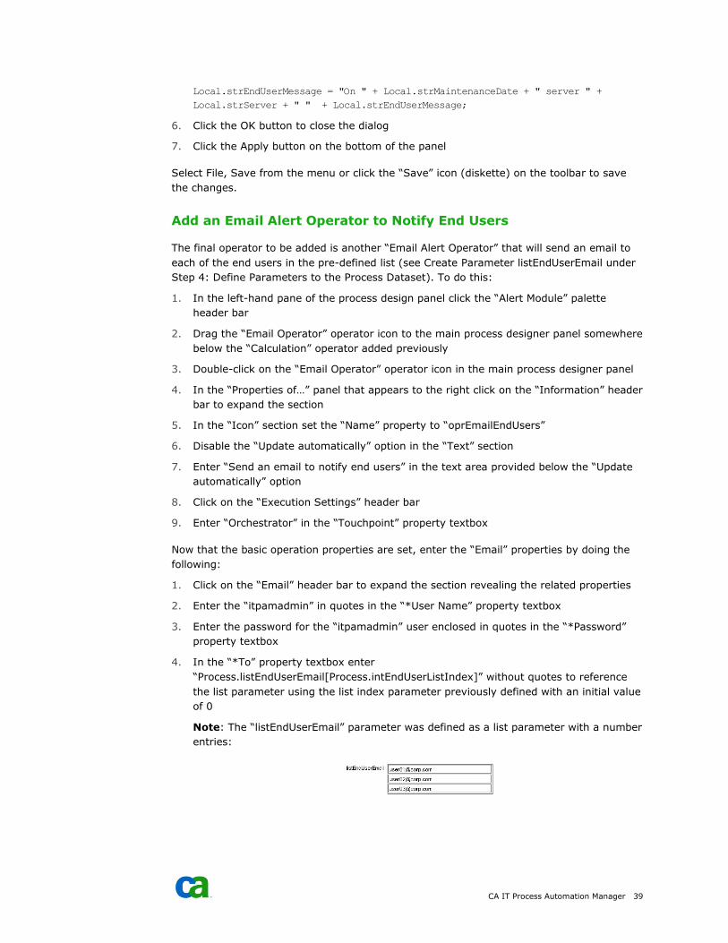
CA IT Process Automation Manager 39
Local.strEndUserMessage = "On " + Local.strMaintenanceDate + " server " +
Local.strServer + " " + Local.strEndUserMessage;
6. Click the OK button to close the dialog
7. Click the Apply button on the bottom of the panel
Select File, Save from the menu or click the “Save” icon (diskette) on the toolbar to save
the changes.
Add an Email Alert Operator to Notify End Users
The final operator to be added is another “Email Alert Operator” that will send an email to
each of the end users in the pre-defined list (see Create Parameter listEndUserEmail under
Step 4: Define Parameters to the Process Dataset). To do this:
1. In the left-hand pane of the process design panel click the “Alert Module” palette
header bar
2. Drag the “Email Operator” operator icon to the main process designer panel somewhere
below the “Calculation” operator added previously
3. Double-click on the “Email Operator” operator icon in the main process designer panel
4. In the “Properties of…” panel that appears to the right click on the “Information” header
bar to expand the section
5. In the “Icon” section set the “Name” property to “oprEmailEndUsers”
6. Disable the “Update automatically” option in the “Text” section
7. Enter “Send an email to notify end users” in the text area provided below the “Update
automatically” option
8. Click on the “Execution Settings” header bar
9. Enter “Orchestrator” in the “Touchpoint” property textbox
Now that the basic operation properties are set, enter the “Email” properties by doing the
following:
1. Click on the “Email” header bar to expand the section revealing the related properties
2. Enter the “itpamadmin” in quotes in the “*User Name” property textbox
3. Enter the password for the “itpamadmin” user enclosed in quotes in the “*Password”
property textbox
4. In the “*To” property textbox enter
“Process.listEndUserEmail[Process.intEndUserListIndex]” without quotes to reference
the list parameter using the list index parameter previously defined with an initial value
of 0
Note: The “listEndUserEmail” parameter was defined as a list parameter with a number
entries:
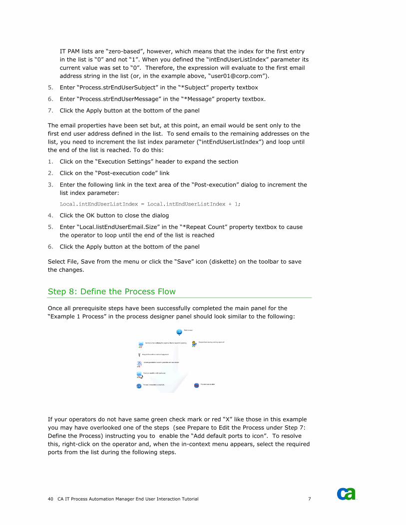
40 CA IT Process Automation Manager End User Interaction Tutorial 7
IT PAM lists are “zero-based”, however, which means that the index for the first entry
in the list is “0” and not “1”. When you defined the “intEndUserListIndex” parameter its
current value was set to “0”. Therefore, the expression will evaluate to the first email
address string in the list (or, in the example above, “[email protected]”).
5. Enter “Process.strEndUserSubject” in the “*Subject” property textbox
6. Enter “Process.strEndUserMessage” in the “*Message” property textbox.
7. Click the Apply button at the bottom of the panel
The email properties have been set but, at this point, an email would be sent only to the
first end user address defined in the list. To send emails to the remaining addresses on the
list, you need to increment the list index parameter (“intEndUserListIndex”) and loop until
the end of the list is reached. To do this:
1. Click on the “Execution Settings” header to expand the section
2. Click on the “Post-execution code” link
3. Enter the following link in the text area of the “Post-execution” dialog to increment the
list index parameter:
Local.intEndUserListIndex = Local.intEndUserListIndex + 1;
4. Click the OK button to close the dialog
5. Enter “Local.listEndUserEmail.Size” in the “*Repeat Count” property textbox to cause
the operator to loop until the end of the list is reached
6. Click the Apply button at the bottom of the panel
Select File, Save from the menu or click the “Save” icon (diskette) on the toolbar to save
the changes.
Step 8: Define the Process Flow
Once all prerequisite steps have been successfully completed the main panel for the
“Example 1 Process” in the process designer panel should look similar to the following:
If your operators do not have same green check mark or red “X” like those in this example
you may have overlooked one of the steps (see Prepare to Edit the Process under Step 7:
Define the Process) instructing you to enable the “Add default ports to icon”. To resolve
this, right-click on the operator and, when the in-context menu appears, select the required
ports from the list during the following steps.
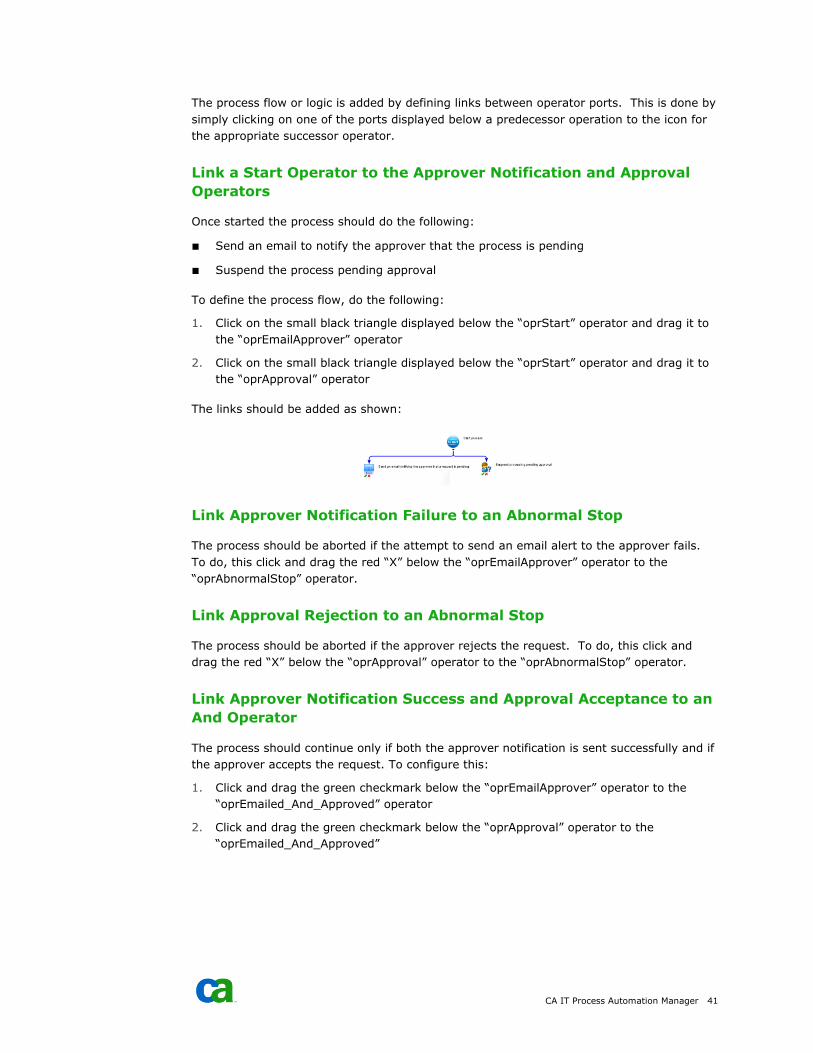
CA IT Process Automation Manager 41
The process flow or logic is added by defining links between operator ports. This is done by
simply clicking on one of the ports displayed below a predecessor operation to the icon for
the appropriate successor operator.
Link a Start Operator to the Approver Notification and Approval
Operators
Once started the process should do the following:
■ Send an email to notify the approver that the process is pending
■ Suspend the process pending approval
To define the process flow, do the following:
1. Click on the small black triangle displayed below the “oprStart” operator and drag it to
the “oprEmailApprover” operator
2. Click on the small black triangle displayed below the “oprStart” operator and drag it to
the “oprApproval” operator
The links should be added as shown:
Link Approver Notification Failure to an Abnormal Stop
The process should be aborted if the attempt to send an email alert to the approver fails.
To do, this click and drag the red “X” below the “oprEmailApprover” operator to the
“oprAbnormalStop” operator.
Link Approval Rejection to an Abnormal Stop
The process should be aborted if the approver rejects the request. To do, this click and
drag the red “X” below the “oprApproval” operator to the “oprAbnormalStop” operator.
Link Approver Notification Success and Approval Acceptance to an
And Operator
The process should continue only if both the approver notification is sent successfully and if
the approver accepts the request. To configure this:
1. Click and drag the green checkmark below the “oprEmailApprover” operator to the
“oprEmailed_And_Approved” operator
2. Click and drag the green checkmark below the “oprApproval” operator to the
“oprEmailed_And_Approved”
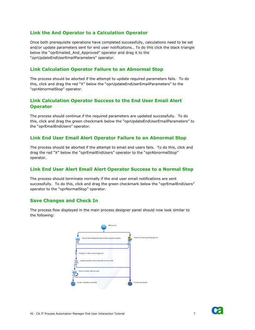
42 CA IT Process Automation Manager End User Interaction Tutorial 7
Link the And Operator to a Calculation Operator
Once both prerequisite operations have completed successfully, calculations need to be set
and/or update parameters sent for end user notifications.. To do this click the black triangle
below the “oprEmailed_And_Approved” operator and drag it to the
“oprUpdateEndUserEmailParameters” operator.
Link Calculation Operator Failure to an Abnormal Stop
The process should be aborted if the attempt to update required parameters fails. To do
this, click and drag the red “X” below the “oprUpdateEndUserEmailParameters” to the
“oprAbnormalStop” operator.
Link Calculation Operator Success to the End User Email Alert
Operator
The process should continue if the required parameters are updated successfully. To do
this, click and drag the green checkmark below the “oprUpdateEndUserEmailParameters” to
the “oprEmailEndUsers” operator.
Link End User Email Alert Operator Failure to an Abnormal Stop
The process should be aborted if the attempt to email end users fails. To do this, click and
drag the red “X” below the “oprEmailEndUsers” operator to the “oprAbnormalStop”
operator.
Link End User Alert Email Alert Operator Success to a Normal Stop
The process should terminate normally if the end user email notifications are sent
successfully. To do this, click and drag the green checkmark below the “oprEmailEndUsers”
operator to the “oprNormalStop” operator.
Save Changes and Check In
The process flow displayed in the main process designer panel should now look similar to
the following:
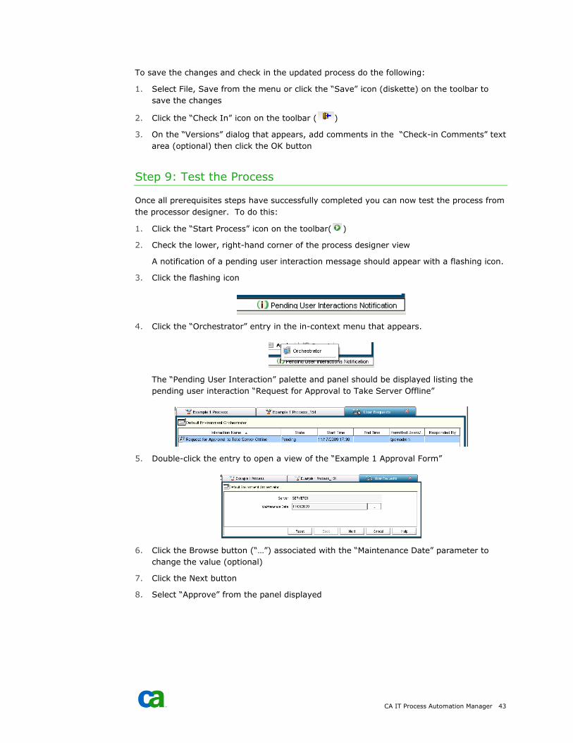
CA IT Process Automation Manager 43
To save the changes and check in the updated process do the following:
1. Select File, Save from the menu or click the “Save” icon (diskette) on the toolbar to
save the changes
2. Click the “Check In” icon on the toolbar ( )
3. On the “Versions” dialog that appears, add comments in the “Check-in Comments” text
area (optional) then click the OK button
Step 9: Test the Process
Once all prerequisites steps have successfully completed you can now test the process from
the processor designer. To do this:
1. Click the “Start Process” icon on the toolbar( )
2. Check the lower, right-hand corner of the process designer view
A notification of a pending user interaction message should appear with a flashing icon.
3. Click the flashing icon
4. Click the “Orchestrator” entry in the in-context menu that appears.
The “Pending User Interaction” palette and panel should be displayed listing the
pending user interaction “Request for Approval to Take Server Offline”
5. Double-click the entry to open a view of the “Example 1 Approval Form”
6. Click the Browse button (“…”) associated with the “Maintenance Date” parameter to
change the value (optional)
7. Click the Next button
8. Select “Approve” from the panel displayed
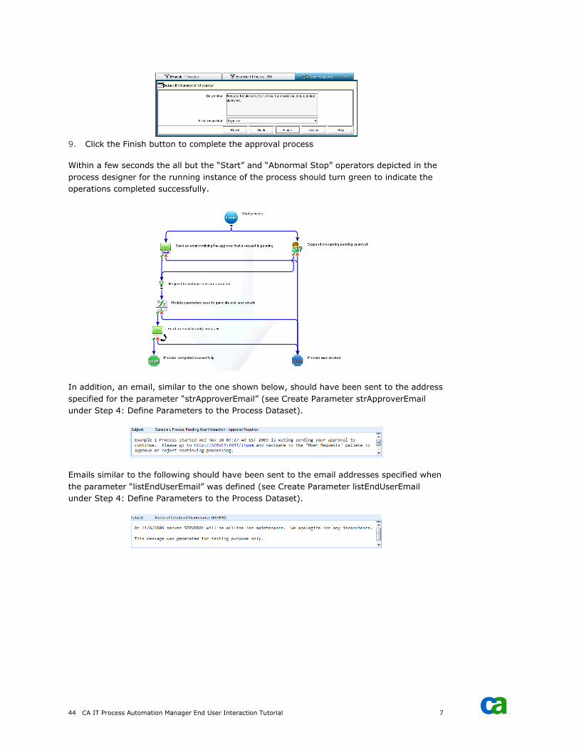
44 CA IT Process Automation Manager End User Interaction Tutorial 7
9. Click the Finish button to complete the approval process
Within a few seconds the all but the “Start” and “Abnormal Stop” operators depicted in the
process designer for the running instance of the process should turn green to indicate the
operations completed successfully.
In addition, an email, similar to the one shown below, should have been sent to the address
specified for the parameter “strApproverEmail” (see Create Parameter strApproverEmail
under Step 4: Define Parameters to the Process Dataset).
Emails similar to the following should have been sent to the email addresses specified when
the parameter “listEndUserEmail” was defined (see Create Parameter listEndUserEmail
under Step 4: Define Parameters to the Process Dataset).
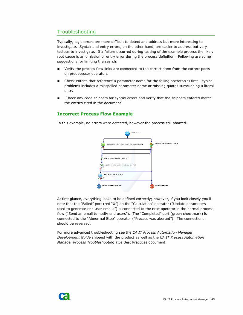
CA IT Process Automation Manager 45
Troubleshooting
Typically, logic errors are more difficult to detect and address but more interesting to
investigate. Syntax and entry errors, on the other hand, are easier to address but very
tedious to investigate. If a failure occurred during testing of the example process the likely
root cause is an omission or entry error during the process definition. Following are some
suggestions for limiting the search:
■ Verify the process flow links are connected to the correct stem from the correct ports
on predecessor operators
■ Check entries that reference a parameter name for the failing operator(s) first – typical
problems includes a misspelled parameter name or missing quotes surrounding a literal
entry
■ Check any code snippets for syntax errors and verify that the snippets entered match
the entries cited in the document
Incorrect Process Flow Example
In this example, no errors were detected, however the process still aborted.
At first glance, everything looks to be defined correctly; however, if you look closely you’ll
note that the “Failed” port (red “X”) on the “Calculation” operator (“Update parameters
used to generate end user emails”) is connected to the next operator in the normal process
flow (“Send an email to notify end users”). The “Completed” port (green checkmark) is
connected to the “Abnormal Stop” operator (“Process was aborted”). The connections
should be reversed.
For more advanced troubleshooting see the CA IT Process Automation Manager
Development Guide shipped with the product as well as the CA IT Process Automation
Manager Process Troubleshooting Tips Best Practices document.

46 CA IT Process Automation Manager End User Interaction Tutorial 7
Initiate the Process
Once you have completed all the preceding steps in this document you can now initiate the
process the way an end user might. To do this:
1. Launch the CA IT Process Automation Manager management console
(http://<server>:<port>/itpam)
2. Login when prompted
3. Locate and click the “User Requests” header bar in the left-hand pane to expand the
palette
4. Navigate to the “Example 1 Start Request Form” in the explore tree (/Example/User
Interaction/Example 1/Example 1 Start Request Form”
5. Right-click on the “Example 1 Start Request Form” node and select “Start Request”
from the in-context menu that appears; the form should appear in the right-hand pane
6. Choose a server and maintenance date then click the Next button
7. Accept the default values and click the Finish button
The right hand pane should revert to the “Start Request Pane” and display an instance of
the processing. Within a few seconds you should see an icon flashing in the bottom right
hand corner of the management console indicating a user interaction is pending. Also
within a few seconds, an email should be delivered to the email address specified for the
approver. To approve or reject the request do the following:
1. Click the “Default Watch” header bar in the left-hand pane to expand the palette
2. Click on the “User Interactions” entry in the list presented
3. Locate the entry in the “User Interactions” list in the right-hand pane the corresponds
to the process referenced in the email that was sent to the approver (by name and
date/time stamp)
4. Double-click the entry to open the approval form
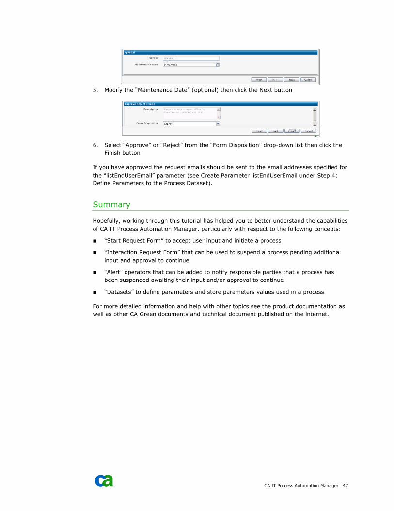
CA IT Process Automation Manager 47
5. Modify the “Maintenance Date” (optional) then click the Next button
6. Select “Approve” or “Reject” from the “Form Disposition” drop-down list then click the
Finish button
If you have approved the request emails should be sent to the email addresses specified for
the “listEndUserEmail” parameter (see Create Parameter listEndUserEmail under Step 4:
Define Parameters to the Process Dataset).
Summary
Hopefully, working through this tutorial has helped you to better understand the capabilities
of CA IT Process Automation Manager, particularly with respect to the following concepts:
■ “Start Request Form” to accept user input and initiate a process
■ “Interaction Request Form” that can be used to suspend a process pending additional
input and approval to continue
■ “Alert” operators that can be added to notify responsible parties that a process has
been suspended awaiting their input and/or approval to continue
■ “Datasets” to define parameters and store parameters values used in a process
For more detailed information and help with other topics see the product documentation as
well as other CA Green documents and technical document published on the internet.