Embed Size (px)
Citation preview
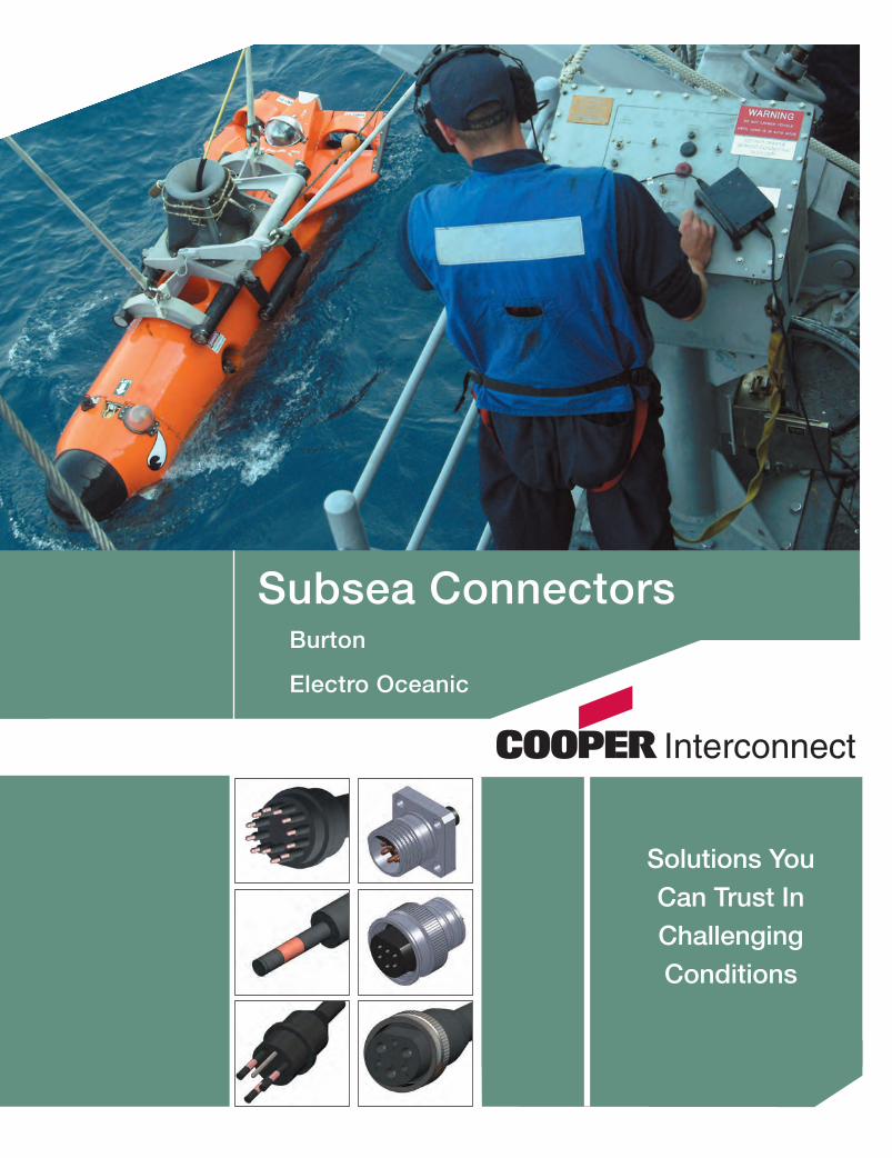
Subsea ConnectorsBurton
Electro Oceanic
Solutions YouCan Trust InChallengingConditions
60704_Cover.qxd:Layout 1 3/1/12 3:37 PM Page 1

Burton 5500 Series
Dry Mate - Pins in Receptacles and Sockets in the Plugs
Overview / Configurations...............................................................................................4–7
Contact Arrangements.....................................................................................................8–9
High Voltage.......................................................................................................................10
PBOF and Accessories................................................................................................11–12
Burton 6600 Series
Dry Mate - Sockets in the Receptacles and Pins in the Plugs
Overview / Configurations...........................................................................................14–17
Contact Arrangements................................................................................................18–19
High Voltage........................................................................................................................20
Accessories.........................................................................................................................21
Burton 5400 Series
High Pressure Penetrators..........................................................................................22–23
Burton Ethernet 5500 and 6600 SeriesDry Mate - Combined Ethernet and Power or Pure Ethernet Solutions.................24–25
Subsea Connectors
750 West Ventura Boulevard Camarillo, CA 93010 www.cooperinterconnect.com
60704_Cover.qxd:Layout 1 3/1/12 3:37 PM Page 2

Burton SC Series
Wet Mate - Rugged A, B, and C Size Standard Circular Connectors......................26–33
Electro Oceanic Series
Underwater Pluggable
Series 51 Male and Female Connector Plugs...........................................................34–35
Series B51 Male and Female Connector Plugs (Accepts Locking Sleeve)............36–37
Series 53 Male and Female Connector Receptacles .............................................. 38–39
Series B53 Male and Female Receptacles (Accepts Locking Sleeve)....................40-41
Series 59 Male/Female Right Angle Receptacles..........................................................42
Series 510 & 52 Two-Pin Male/Female.......................................................................43–44
Series 610 Magnetically Operated Switch.......................................................................45
Series 41 Penetrators...................................................................................................46–47
Junction Boxes and Locking Sleeves........................................................................48–49
Series 56 Miniature Connectors and WP Series.......................................................50–52
Capabilities/Appendix...............................................................................................53–56
Cooper Interconnect 750 West Ventura Boulevard Camarillo, CA 93010 (805) 484-0543 Fax: (805) 987-5062 1
60704_Text_v9_C9599 Cooper_Subsea Cat_p1-19 3/2/12 12:49 PM Page 1

Underwater Solutions for Harsh Environments
Cooper Interconnect offers one of the most comprehensive product linesof connectors and cable assemblies for Subsea and Underwaterenvironments.
No matter how harsh the environment, Cooper Interconnect providesconnectors designed for the toughest conditions, whether requiring ahydrostatic pressure of 20,000 PSI, or ensuring a perfect working camerafor an underwater marine picture.
Whatever your underwater interconnection need, Cooper Interconnecthas a solution for you.
750 West Ventura Boulevard Camarillo, CA 93010 www.cooperinterconnect.com 2
60704_Text_v9_C9599 Cooper_Subsea Cat_p1-19 3/2/12 12:49 PM Page 2

Burton Connectors
The Burton name is one of the most trusted in the subsea world, offeringhigh-quality, rugged connectors for the most demanding applications.They are designed for durability and extreme reliability.
Trust your interconnect needs to Cooper Interconnect’s Burtonconnectors.
Solid works models and PDF drawings available upon request.
Cooper Interconnect 750 West Ventura Boulevard Camarillo, CA 93010 (805) 484-0543 Fax: (805) 987-5062 3
60704_Text_v9_C9599 Cooper_Subsea Cat_p1-19 3/2/12 12:49 PM Page 3

5500 Series OverviewBURTON
1 Cable
2 Conductor
3 Socket
4 Molded Body
5 Metal Shell
6 Locking Ring
7 Keyway
8 Metal Shell
9 Pin
10 Pigtails
Pressure Rating 10,000 PSI
Voltage Rating 600 - 3000
Ampacity See Appendix
Data and Specifications
Part Number System55 0 1 - 24 20 - 0004
Number of contacts
Shell size
Series
Style:1-CCP2-CCR6-FDCR7-BCR
Special designation:
A-Attachable
R-Right angle
0-600v (standard)
1-1000v
2-2000v
3-3000v
9-1100v (special)
�
�
�
�
�
��
�
�
Shell Bolt Torque15 #10 25 lb-In
16 #10 25 lb-In
20 1/4 45 lb-In
24 1/4 45 lb-In
32 5/16 85 lb-In
The 5500 Series is anextremely rugged and reli-able underwater electricalconnector. It is the standardBurton connector series withpins in the receptacles andsockets in the plugs.
The pin and socket relation-ship is due to the fact that inmost applications, powerruns from the plug into thereceptacle. For safety rea-sons, it is desirable never tohave power available on thepin side. For reverse powerapplications, refer to Burton’s6600 Series.
For over four decades, theBurton 5500 Series has beenthe industry standard con-nector for applications,which require reliable servicein severe situations. Therugged metal shells,recessed pins, and face-type seals assure depend-able service in the mostdemanding situations
FCR
Shell Torque15 125 lb-In
16 125 lb-In
20 165 lb-In
24 225 lb-In
32 335 lb-In
Receptacle InstallationBulkhead connectors shouldbe torqued to the followingspecifications.
For panel mount receptacles,use 4 bolts to hold them inplace. Recommended sizesand torques are:
Length in feet or assembly length
Materials
Contact High cond. copper alloy
Penetrator Shell 316L SS (passivated)Titanium, Monel, and
other materials availableupon request
Penetrator Body Integrally molded elastomer
Cable UL SOW-A or Mil-C-915
Pigtails Mil-W-16878
5501-1508-0004
5507-1508-0004
750 West Ventura Boulevard Camarillo, CA 93010 www.cooperinterconnect.com 4
60704_Text_v9_C9599 Cooper_Subsea Cat_p1-19 3/2/12 12:49 PM Page 4

5500 Series AssemblyBURTON
The 5500 Series has a number of features which aredesigned to make them rugged and reliable even in severeservice. Use the Burton 5500 Series for mission critical appli-cations.
5500 Series FeaturesBurton 5500 Series connectors have no O-Ring sealbetween the plug and receptacle. Our seal is a face-typeseal integrally molded as part of the plug and cannot fall off.
Stub acme threads are used on the 16-size and larger shells.Stub acme threads are difficult to cross thread or damage.
The electrical contacts have crimp connections to the con-ductor; not solder joints. Crimp contacts have superior flexlife compared to soldered joints.
All elastomer to metal bonding surfaces are sandblasted,cleaned, and primed. Then units are molded under severalthousand pounds of pressure for 20 or minutes at high temperature. This assures a complete bond which prevents water migration.
Receptacle FeaturesThe Burton 5500 Series receptacles have a unique water blocking system. The water blocking exists down to the conductor level. This means that in the event of a catastrophic failure of the con-nector system, such as the plug being torn away from thereceptacle, water will not enter your valuable equipment.Many competing connector lines do not waterblock down tothe conductor level.
The pins are completely contained within the envelope of themetal shell. This means that pins will not be bent or dam-aged when the connector has been impacted or stepped on.
Plug FeaturesThe plugs have a metal shell under the elastomeric body. Itmakes them very rugged and resistant to flexing damage.
The plug contacts are completely bonded and isolated fromeach other. This means that if the cable jacket is damagedand water migrates into the plug, electrical integrity can be maintained.
5500 Series Assembly Dimensions in English (Metric)
Shell Size A B C D E F G H J K L
15 0.65 (16.5)
0.68(17.3)
1.9549.5)
0.31(7.9)
3.19(81.0)
2.75(69.9)
2.12(53.8)
0.68(17.3)
1.30(33.0)
3.00(76.2)
1.78(45.2)
16 0.65(16.6)
0.68(17.8)
2.12(53.8)
0.38(9.7)
--- --- --- 0.68(17.0)
1.30(33.0)
3.89(98.8)
2.45(62.2)
20 0.77(19.6)
0.79(20.1)
2.31(58.7)
0.38(9.7)
3.97(100.8)
3.24(82.3)
2.90(73.7)
0.79(20.1)
1.44(36.6)
5.40(137.2)
2.75(69.9)
24 1.02(25.9)
1.04(26.4)
2.66(67.6)
0.38(9.7)
4.50(114.3)
3.87(98.3)
3.25(82.6)
1.05(26.7)
1.73(43.9)
5.43(137.9)
2.80(71.1)
32 1.52(38.6)
1.54(39.1)
3.50(88.9)
0.38(9.7)
5.13(130.3
4.50(114.3)
4.59(116.6)
1.55(39.4)
2.31(58.7)
6.12(155.4)
3.94(100.1)
SURFACE FINISH
SURFACE FINISH
Cooper Interconnect 750 West Ventura Boulevard Camarillo, CA 93010 (805) 484-0543 Fax: (805) 987-5062 5
60704_Text_v9_C9599 Cooper_Subsea Cat_p1-19 3/2/12 12:49 PM Page 5

5500 Series Connector ConfigurationsBURTON
Please refer to the illustrations on the facing page. The receptacles (which have pin contacts) are shown on the top. The plugs(which have socket contacts) are shown on the bottom. This is the standard arrangement as power normally flows from theplug into the socket. For safety reasons, the possibility of live power on pins should not be allowed. If the reverse contactarrangement is required, please refer to the Burton 6600 Series.
The descriptions below correspond to the illustration to the right. The part number refers to the first 4 digits of the part num-ber.
BCR Bulkhead Connector Receptacle (5507)Less expensive than the FCR, this is the standard receptacle mount. It may be used with any plugs. When using the BCR witha right angle plug (CCP-RA), a BCR retaining ring must be used instead of tapped threads. This is due to keyway orientation.
FCR Flange Connector Receptacle (5506)Like the BCR, this is a mounted receptacle. It is more expensive since it is machined from a larger block of stainless steel. Itis also more difficult to mount since it requires five holes instead of one. However, it is ideal for use with the right angle plugsince keyway orientation can be controlled. It is possible to get this receptacle with an extra O-Ring seal mounted on theF surface for an additional piston type seal (available by special order).
CCR Cable Connector Receptacle (5502)An in-line receptacle mounted on a cable. It can be used as part of a cable splice unit or other specialized application.
CCR-AT, Attachable (55A2)Used in the same applications as the CCR except that it is designed to be attached to its cable by the customer.
CCP Cable Connector Plug (5501)The standard plug for most applications. Like all of the plugs, it mates to any of the receptacles. This plug is molded tocable at the Cooper Interconnect factory.
CCP-RA Cable connector Plug, Right Angle (55R1)This plug should be used when the cable must exit the receptacle at a 90-degree angle. Normally, the FCR is recommendedfor use with the right angle plug to assure keyway orientation.
CCP-AT Cable Connector Plug, Attachable (55A1)Used in the same applications as the CCP except that it is designed to be attached to its cable by the customer. A variationof this plug is available as a PBOF (pressure balanced oil filled) assembly. The connector shell is modified to accept a newbackshell, which has an oil fill port and a hose attachment. Please see page 11 for details.
5500 Series Dimensions in English (Metric)
Shell Size
5Athd*
5B 5C 5D 5E 5F 5G 5H thd* 5J 5K 5L 5Mdia
5N 5Pdia
5R O-Ring 5S 5Tdia
5U 5X
15 15/16-20
2.45(62.2)
1.09(27.7)
1.13(28.6)
1.25(31.8)
0.50(12.7)
0.31(7.92)
5/8-18 1.00(25.4)
1.50(38.10)
2.12(53.8)
0.63(15.88)
1.47(37.3)
0.78(19.8)
1.55(39.4)
-116 0.68(17.35)
0.22(5.563)
2.75(69.9)
2.87(72.9)
16 1-9 3.31(84.1)
1.17(29.7)
1.13(28.6)
1.50(38.1)
0.50(12.7)
0.38(9.53)
5/8-18 1.13(28.6)
10.63(41.28)
— 0.63(15.88)
— — — -116 — 0.22(5.563)
— —
20 1-1/4-9 4.80(121.9)
1.50(38.1)
1.25(31.8)
1.50(38.1)
0.50(12.7)
0.38(9.53)
3/4-16 1.25(31.8)
1.75(44.45)
2.90(73.7)
0.74(18.80)
1.59(40.4)
1.06(26.9)
1.66(42.2)
-118 1.087(27.61)
0.28(7.137)
3.24(82.3)
4.10(104.1)
24 1-1/2-9 4.80(121.9)
1.75(44.5)
1.50(38.1)
1.50(38.1)
0.50(12.7)
0.38(9.53)
1-14 1.50(38.1)
2.00(50.80)
3.25(82.6)
0.99(25.15)
1.68(42.7)
1.32(33.5)
1.66(42.2)
-122 1.32(33.63)
0.28(7.137)
3.87(98.3)
4.88(124.0)
32 2-9 5.57(141.5)
2.25(57.2)
2.00(50.8)
1.50(38.1)
0.50(12.7)
0.38(9.53)
2-9 2.00(50.8)
2.63(66.68)
4.59(116.6)
1.49(37.85)
1.70(43.2)
1.81(46.0)
1.78(42.2)
-130 1.81(46.02)
0.34(8.738)
4.50(114.3)
5.57(101.6)
750 West Ventura Boulevard Camarillo, CA 93010 www.cooperinterconnect.com 6
60704_Text_v9_C9599 Cooper_Subsea Cat_p1-19 3/2/12 12:49 PM Page 6

5500 Series Connector ConfigurationsBURTON
BCRRECEPTACLE, BULKHEAD
PIN INSERT5507 SERIES
FCRRECEPTACLE, FLANGE
PIN INSERT5506 SERIES
CCRRECEPTACLE, CABLE
PIN INSERT5502 SERIES
CCR-ATRECEPTACLE, ATTACHABLE
55A2 SERIES
CCPPLUG, CABLESOCKET INSERT5501 SERIES
CCP-ATPLUG, ATTACHABLE
55A1 SERIES
CCP-RAPLUG, RIGHT ANGLE
SOCKET INSERT55R1 SERIES
5E
5E
5F
5F
5X
5N
5P
5C
5U
5C
5R
5C 5S
5L
5B
PIGTAILS
PIGTAILS
CABLE
CABLE
CABLE
ASSEMBLY LENGTH
ASSEMBLY LENGTH
ASSEMBLYLENGTH
POLARIZATIONKEY WAY
5H THREAD0-RING
5A THREAD
5M
0-RING5A THREAD
5A THREAD
5A THREAD
5T HOLE
5G
5G
5D
5K
5J
Cooper Interconnect 750 West Ventura Boulevard Camarillo, CA 93010 (805) 484-0543 Fax: (805) 987-5062 7
60704_Text_v9_C9599 Cooper_Subsea Cat_p1-19 3/2/12 12:49 PM Page 7

5500 Series Contact ArrangementsBURTON
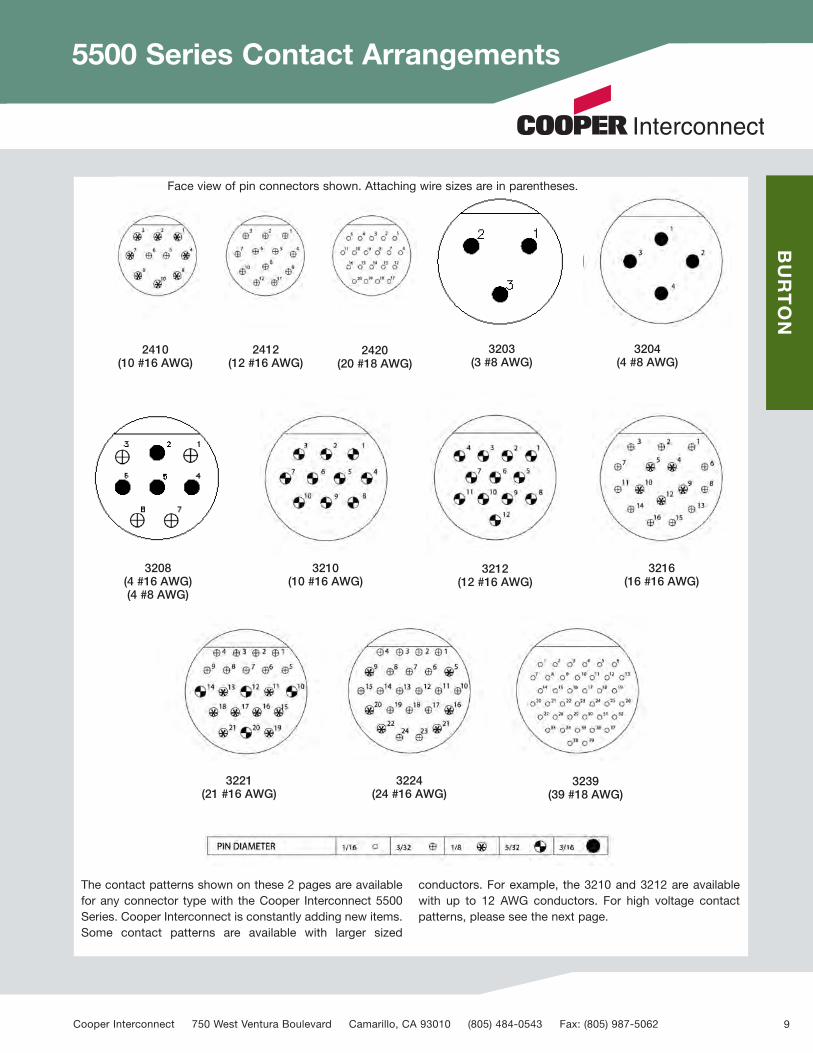
Face view of pin connectors shown. Attaching wire sizes are in parentheses.
1502(2 #16 AWG)
1503(3 #16 AWG)
1504(4 #18 AWG)
1506(6 #18 AWG)
1508(8 #18 AWG)
1602(2 #16 AWG)
1603(3 #16 AWG)
1604(4 #18 AWG)
1606(6 #18 AWG)
1608(8 #18 AWG)
1610(10 #18 AWG)
2003(3 #16 AWG)
2004(4 #16 AWG)
2006(6 #16 AWG)
2008(8 #16 AWG)
20A8(8 #16 AWG)
20B3(3 #16 AWG)
2013(13 #18 AWG)
2021(21 #18 AWG)
750 West Ventura Boulevard Camarillo, CA 93010 www.cooperinterconnect.com 8
60704_Text_v9_C9599 Cooper_Subsea Cat_p1-19 3/2/12 12:49 PM Page 8
5500 Series Contact ArrangementsBURTON
The contact patterns shown on these 2 pages are availablefor any connector type with the Cooper Interconnect 5500Series. Cooper Interconnect is constantly adding new items.Some contact patterns are available with larger sized
conductors. For example, the 3210 and 3212 are availablewith up to 12 AWG conductors. For high voltage contactpatterns, please see the next page.
Face view of pin connectors shown. Attaching wire sizes are in parentheses.
2410(10 #16 AWG)
2412(12 #16 AWG)
2420(20 #18 AWG)
3203(3 #8 AWG)
3204(4 #8 AWG)
3208(4 #16 AWG)(4 #8 AWG)
3210(10 #16 AWG)
3212(12 #16 AWG)
3216(16 #16 AWG)
3221(21 #16 AWG)
3224(24 #16 AWG)
3239(39 #18 AWG)
Cooper Interconnect 750 West Ventura Boulevard Camarillo, CA 93010 (805) 484-0543 Fax: (805) 987-5062 9
60704_Text_v9_C9599 Cooper_Subsea Cat_p1-19 3/2/12 12:49 PM Page 9

5500 Series High Voltage ConnectorsBURTON
5500 Series High Voltage Connectors
A number of 5500 Series contact patterns are available with higher voltage rat-ings (standard rating is 600v). Ratings of 1000v, 2000v, and 3000v are available.Due to certain design constraints and material limitations, not all patterns areavailable in all voltage ratings.
The Burton 5500 Series high voltage connectors differ from the standard ratedunits in several areas. There is a contact shoulder, which increases the surfacetrack distance between contacts. Different insulation materials may also be used.
All Cooper Interconnect high voltage connectors differ from the standard ratedunits in several areas. There is a contact shoulder, which increases the surfacetrack distance between contacts. Different insulation materials may also be used.
All Cooper Interconnect high voltage connectors are built to be equally ruggedand reliable as the standard voltage rated items.
The following contact patterns are available. Cooper Interconnect is continuous-ly adding products; please contact the factory for availability of other patterns orspecific requirements.
High Voltage AvailabilityPattern 1000v 2000v 3000v1502 X X
1503 X X
2004 X X X
2006 X
2013 X
2403 X X X
2410 X X
2420 X
3203 X X X
3204 X X X
3210 X X X
3212 X X
3215 X X X
3224 X
3239 X
Face view of pin connectors shown. Attaching wire sizes are in parentheses.
1502(2 #18 AWG)
1503(3 #18 AWG)
1603(3 #16 AWG) 2006
(6 #16 AWG)2004
(4 #14 AWG)2013
(13 #18 AWG)
2403(3 #14 AWG)
2410(10 #16 AWG)
2420(20 #18 AWG) 3203
(3 #8 AWG)3204
(4 #8 AWG)
3210(10 #14 AWG)
3212(12 #14 AWG)
3215(15 #18 AWG)
3224(24 #18 AWG)
3239(39 #18 AWG)
750 West Ventura Boulevard Camarillo, CA 93010 www.cooperinterconnect.com 10
60704_Text_v9_C9599 Cooper_Subsea Cat_p1-19 3/2/12 12:49 PM Page 10

5500 Series PBOF PlugsBURTON
Pressure Balanced Oil Filled (PBOF)
The 5500 plugs are also available in PBOF form fac-tor. The plug is a modified 55A1 attachable designedto accommodate a special backshell which has ahose barb and oil fill port. The part number becomes55P1-XXXX-0000.
For special extreme applications, a JIC type fitting isavailable on the backshell. This makes it possible to usea hydraulic hose instead of clear tubing.
PBOF connectors may be ordered separately or madeup as cable assemblies. Due to the difficulty of shippingcable assemblies with oil, we leave that to the customer.
Shell Size A B C D
9 2.29 1.72 0.66 0.40
15 3.80 2.75 1.12 0.67
16 3.95 2.80 1.25 0.67
20 4.04 2.94 1.50 0.67
24 4.19 3.22 1.75 0.67
32 4.25 3.22 2.22 1.00
A
B
D
C
Cooper Interconnect 750 West Ventura Boulevard Camarillo, CA 93010 (805) 484-0543 Fax: (805) 987-5062 11
60704_Text_v9_C9599 Cooper_Subsea Cat_p1-19 3/2/12 12:49 PM Page 11

5500 Series AccessoriesBURTON
A number of accessories are available for the 5500Series. Some are shown on this page. Please contact thefactory for specific requests.
FCR Mounting CoverSize Part Number15 5106-1500-0000
16 5106-1600-0000
20 5106-2000-0000
24 5106-2400-000032 5106-3200-0000
BCR Mounting PlugSize Part Number15 5107-1500-0000
16 5107-1600-0000
20 5107-2000-0000
24 5107-2400-0000
32 5107-3200-0000
BCR Retaining RingSize Part Number15 5109-1500-0000
16 5109-1600-0000
20 5109-2000-0000
24 5109-2400-0000
32 5109-3200-0000
Plug Dust Cap (hard rubber)Size Part Number15 6700-0125-0151
16 6700-0125-0161
20 6700-0125-0201
24 6700-0125-0241
32 6700-0125-0321
Receptacle Pressure Cap (SS)Size Part Number15 5101-1500-0000
16 5101-1600-0000
20 5101-2000-0000
24 5101-2400-0000
32 5101-3200-0000
Receptacle Dust Cap (hard rubber)Size Part Number15 6700-0124-0151
16 6700-0124-0161
20 6700-0124-0201
24 6700-0124-0241
32 6700-0124-0321
Dummy PlugSize Part Number15 5501-15XX-0000
16 5501-16XX-0000
20 5501-20XX-0000
24 5501-24XX-0000
32 5501-32XX-0000
Dummy Plugs need to be used when full work-ing pressure is required. Dummy Plugs areavailable for all sizes of cables and recepta-cles. Size the dummy plug as you would themating connector.
Pressure caps rated to 500psi
750 West Ventura Boulevard Camarillo, CA 93010 www.cooperinterconnect.com 12
60704_Text_v9_C9599 Cooper_Subsea Cat_p1-19 3/2/12 12:49 PM Page 12
5500 Series Custom SolutionsBURTON
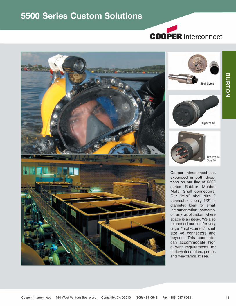
Cooper Interconnect hasexpanded in both direc-tions on our line of 5500series Rubber MoldedMetal Shell connectors.Our “Mini” shell size 9connector is only 1/2” indiameter. Ideal for smallinstrumentation, cameras,or any application wherespace is an issue. We alsoexpanded our line for verylarge “high-current” shellsize 48 connectors andbeyond. This connectorcan accommodate highcurrent requirements forunderwater motors, pumpsand windfarms at sea.
Shell Size 9
Plug Size 48
ReceptacleSize 48
Cooper Interconnect 750 West Ventura Boulevard Camarillo, CA 93010 (805) 484-0543 Fax: (805) 987-5062 13
60704_Text_v9_C9599 Cooper_Subsea Cat_p1-19 3/2/12 12:50 PM Page 13

BURTON
6600 Series Assembly
The 6600 Series is anextremely rugged and reli-able underwater electricalconnector. It is the alternateBurton connector series withpin in the plugs and socketsin the receptacles (theinverse of the 5500 series).
Occasionally, it is desirableto run power from the receptacle to the plug (for example a power supply or battery pack). In theseinstances, use the 6600Series. For safety reasons, itis desirable to never havepower available on the pinside. For reverse (standard)power applications, refer to Burton’s 5500 Series.Along with the Burton 5500Series, the 6600 Series has for over two decadesbecome the industry stan-dard connector for applica-tions, which require reliableservice in severe situations.The rugged metal shells,recessed pins, and face typeseals assure dependableservice in the most demand-ing situations.
1 Cable
2 Conductor
3 Pin
4 Molded Body
5 Metal Shell
6 Locking Ring
7 Recept. Face
8 Metal Shell
9 Socket
10 Pigtails
11 Epoxy Backfill
Pressure Rating 10,000 PSI
Voltage Rating 600 – 3000
Ampacity See Appendix
Contacts High cond. copper alloy
Penetrator Shell 316L SS (passivated)
Penetrator Body Integrally molded elastomer
Cable UL SOW-A or Mil-C-915
Pigtails Mil-W-16878
Data and Specifications
Part Number System
Materials
66 0 1 - 24 20 - 0004
Length in feet
Number of contacts
Shell size
Series
Style:1-CCP2-CCR6-FCR7-BCR
Special designation:
A-Attachable
R-Right angle
0-600v (standard)
1-1000v
2-2000v
3-3000v
9-1100v (special)
�
�
�
�
�
�
�
�
�
�
750 West Ventura Boulevard Camarillo, CA 93010 www.cooperinterconnect.com 14
60704_Text_v9_C9599 Cooper_Subsea Cat_p1-19 3/2/12 12:50 PM Page 14

BURTON
Like the 5500 Series, the 6600 Series has a number of fea-tures which are designed to make them rugged and reliableeven in severe service. Use the Burton 6600 Series for mis-sion critical applications where you need power flowing inopposite the usual direction.
6600 Series FeaturesBurton 6600 Series connectors have no O-Ring seal betweenthe plug and receptacle. That seal is a face type seal integral-ly molded as part of the plug and cannot fall off.
Stub acme threads are used on all shell sizes. Stub acmethreads are difficult to cross thread or damage.
The electrical contacts have crimp connections to the con-ductor; not solder joints. Crimp contacts have superior flexlife compared to soldered joints.
All elastomer to metal bonding surfaces are sandblasted,cleaned and primed. Then units are molded under severalthousand pounds of pressure for 20 or more minutes at 300+degrees. This assures a complete bond which preventswater migration.
Receptacle FeaturesLike the Cooper Interconnect 5500 Series, the 6600 Seriesreceptacles have a unique water blocking system. The waterblocking exists down to the conductor level. This means thatin the event of a catastrophic failure of the connector systemsuch as the plug being torn away from the receptacle – waterwill not enter your valuable equipment. Many competing con-nector lines do not water block down to the conductor level.
Plug FeaturesThe plugs have a metal shell under the elastomeric body.
It makes them very rugged and resistant to flexing damage.
The pins are completely contained within the envelope of themetal shell. This means that the pins will not be bent or dam-aged when the connector has been impacted or stepped on.
The plug contacts are completely bonded and isolated fromeach other. This means that if the cable jacket is damagedand water migrates into the plug, electrical integrity can bemaintained.
6600 Series Overview
SURFACE FINISH
SURFACE FINISH
6600 Series Assembly Dimensions in English (Metric)
Shell Size A B C D E F G H J K L
16 0.64(16.3)
0.66(16.8)
2.12(54.6)
0.375(9.5)
--- --- --- 0.79(20.1)
1.44(36.6)
3.72(94.5)
2.15(54.6)
20 0.77(19.6)
0.79(20.1)
2.28(57.9)
0.375(9.5)
4.00(101.6)
3.24(82.3)
2.90(73.7)
0.79(20.1)
1.44(36.6)
5.26(133.6)
2.14(54.4)
24 1.02(25.9)
1.04(26.4)
2.63(66.8)
0.375(9.5)
4.50(114.3)
3.87(98.3)
3.25(82.6)
1.05(26.7)
1.73(43.9)
5.87(149.1)
2.30(59.2)
32 1.52(38.6)
1.54(39.1)
3.50(88.9)
0.375(9.5)
5.13(130.3
4.50(114.3)
4.59(116.6)
1.55(39.4)
2.31(58.7)
6.57(166.9)
3.50(88.9)
Cooper Interconnect 750 West Ventura Boulevard Camarillo, CA 93010 (805) 484-0543 Fax: (805) 987-5062 15
60704_Text_v9_C9599 Cooper_Subsea Cat_p1-19 3/2/12 12:50 PM Page 15

BURTON
6600 Series Configurations
Please refer to the illustration on the facing page. The receptacles (which have socket contacts) are shown on the top. The plugs(which have pin contacts) are shown on the bottom. This pin/socket relationship is opposite of the 5500 Series. It is used foroccasions where you wish power to flow from the receptacle to the plug. For safety reasons, the possibility of live power onpins should not be allowed. If the reverse contact arrangement is required, please refer to the Burton 5500 Series.
The descriptions below correspond to the illustration to the right. The part numbers refers to the first 4 digits of the part num-ber.
BCR Bulkhead Connector Receptacle (6607)Less expensive than the FCR, this is the standard receptacle mount. It may be used with any plugs. When using the BCR witha right angle plug (CCP-RA), a BCR retaining ring must be used instead of tapped threads. This is due to keyway orientation.
FCR Flange Connector Receptacle (6606)Like the BCR, this is a mounted receptacle. It is more expensive since it is machined from a larger block of stainless steel.It is also more difficult to mount since it requires 5 holes instead of 1. However, it is ideal for use with the right angle plugsince keyway orientation can be controlled. It is possible to get this receptacle with an extra O-Ring seal mounted on theF surface for an additional piston type seal (available by special order).
CCR Cable Connector Receptacle (6602)An in-line receptacle mounted on a cable. It can be used as part of a cable splice unit or other specialized application.
CCR-AT, Attachable (66A2)Used in the same applications as the CCR except that it is designed to be attached to its cable by the customer.
CCP Cable Connector Plug (6601)The standard plug for most applications. Like all of the plugs, it mates to any of the receptacles. This plug is molded tocable at the Cooper Interconnect factory.
CCP-RA Cable Connector Plug, Right Angle (66R1)This plug should be used when the cable must exit the receptacle at a 90-degree angle. Normally, the FCR is recommendedfor use with the right angle plug to assure keyway orientation.
CCP-AT Cable Connector Plug, Attachable (66A1)Used in the same applications as the CCP except that it is designed to be attached to its cable by the customer. A varia-tion of this plug is available as a PBOF (pressure balanced oil filled) assembly. The connector shell is modified to accept anew backshell, which has an oil fill port and a hose attachment. Please consult the factory for details.
6600 Series Dimensions in English (Metric)
Shell Size
6Athd*
6
6B 6C 6D 6E 6F 6G 6H thd* 6J 6K 6L 6Mdia
6N 6Pdia
6R O-Ring 6S 6Tdia
6U 6X
16 1-9 3.01(76.5)
1.17(29.7)
1.13(28.6)
1.50(38.1)
0.50(12.7)
0.375(9.53)
5/8-18 1.125(28.6)
10.625(41.28)
— 0.615(15.62)
— — 1.72(43.7)
-116 0.837(21.26)
0.219(5.563)
— —
20 1-1/4-9 3.74(95.0)
1.50(38.1)
1.25(31.8)
1.50(38.1)
0.50(12.7)
0.375(9.53)
3/4-16 1.25(31.8)
1.75(44.45)
2.90(73.7)
0.74(18.80)
1.59(40.4)
1.06(26.9)
1.62(41.1)
-118 1.087(27.61)
0.281(7.137)
3.24(82.3)
4.12(104.7)
24 1-1/2-9 4.33(110.0)
1.75(44.5)
1.50(38.1)
1.50(38.1)
0.50(12.7)
0.375(9.53)
1-14 1.50(38.1)
2.00(50.80)
3.57(73.7)
0.99(25.15)
1.68(42.7)
1.32(33.5)
1.62(41.1)
-122 1.32(33.63)
0.281(7.137)
3.87(98.3)
4.78(121.4)
32 2-9 5.07(128.8)
2.25(57.2)
2.00(50.8)
1.50(38.1)
0.50(12.7)
0.375(9.53)
2-9 2.00(50.8)
2.63(66.68)
4.59(116.6)
1.49(37.85)
1.70(43.2)
1.81(46.0)
1.62(41.1)
-130 1.81(46.02)
0.344(8.738)
4.50(114.3)
5.47(138.9)
750 West Ventura Boulevard Camarillo, CA 93010 www.cooperinterconnect.com 16
60704_Text_v9_C9599 Cooper_Subsea Cat_p1-19 3/2/12 12:50 PM Page 16

BURTON
6600 Series Configurations
6P
6N
6A THREAD
6C
6R
6S
6A THREAD
6M
O-RING
PIGTAILS
6F
6G
ASSY LENGTH6E
6T HOLE
6K
6J
6A THREAD6H THREAD
PIGTAILS
O-RING
ASSY LENGTH
6G
6F
6E
6D
CABLE
6C
6B
ASSY LENGTH
6L
CABLE
ASSY LENGTH
6C
6U
6A THREAD
6X
CABLE
ASSY LENGTH
GROOVEPOLARIZING
BCRRECEPTACLE, BULKHEAD
SOCKET INSERT6607 SERIES
FCRRECEPTACLE, FLANGE
SOCKET INSERT6606 SERIES
CCRRECEPTACLE, CABLE
SOCKET INSERT6602 SERIES
CCR-ATRECEPTACLE, ATTACHABLE
66A2 SERIES
CCPPLUG, CABLE
PIN INSERT6601 SERIES
CCP-ATPLUG, ATTACHABLE
66A1 SERIES
CCP-RAPLUG, RIGHT ANGLE
PIN INSERT66R1 SERIES
6E6F
PIGTAILS
CABLE
ASSEMBLY LENGTH
ASSEMBLY LENGTH
POLARIZATIONGROOVE
6H THREAD0-RING 6A THREAD
6T HOLE
6G
6E6K
6J
6F
PIGTAILS
0-RING6A THREAD
ASSEMBLY LENGTH
6X
CABLE
ASSEMBLY LENGTH6B
CABLE
ASSEMBLY LENGTH
6L
6C
6S6C
6R
6U
6A THREAD
6N
6P
6A THREAD
6G
6M
6D
Cooper Interconnect 750 West Ventura Boulevard Camarillo, CA 93010 (805) 484-0543 Fax: (805) 987-5062 17
60704_Text_v9_C9599 Cooper_Subsea Cat_p1-19 3/2/12 12:50 PM Page 17

BURTON
6600 Series Contact Arrangements
Face view of pin connectors shown. Attaching wire sizes are in parentheses.
1603(3 #16 AWG)
1608(8 #18 AWG)
1604(4 #18 AWG)
1606(6 #18 AWG)
2003(3 #16 AWG)
2004(4 #16 AWG)
2006(6 #18 AWG)
2008(8 #18 AWG)
2013(13 #18 AWG)
2404(4 #12 AWG)
2406(6 #16 AWG)
2408(8 #16 AWG)
2410(10 #16 AWG)
2420(20 #18 AWG)
750 West Ventura Boulevard Camarillo, CA 93010 www.cooperinterconnect.com 18
60704_Text_v9_C9599 Cooper_Subsea Cat_p1-19 3/2/12 12:50 PM Page 18

BURTON
6600 Series Contact Arrangements
The contact patterns shown on these two pages are availablefor any connector type with the Cooper Interconnect 6600Series. All Cooper Interconnect 6600 Series connectors are
available in high voltage ratings. Please contact the factoryfor details.
Face view of pin connectors shown. Attaching wire sizes are in parentheses.
Cooper Interconnect 750 West Ventura Boulevard Camarillo, CA 93010 (805) 484-0543 Fax: (805) 987-5062 19
60704_Text_v9_C9599 Cooper_Subsea Cat_p1-19 3/2/12 12:50 PM Page 19
BURTON
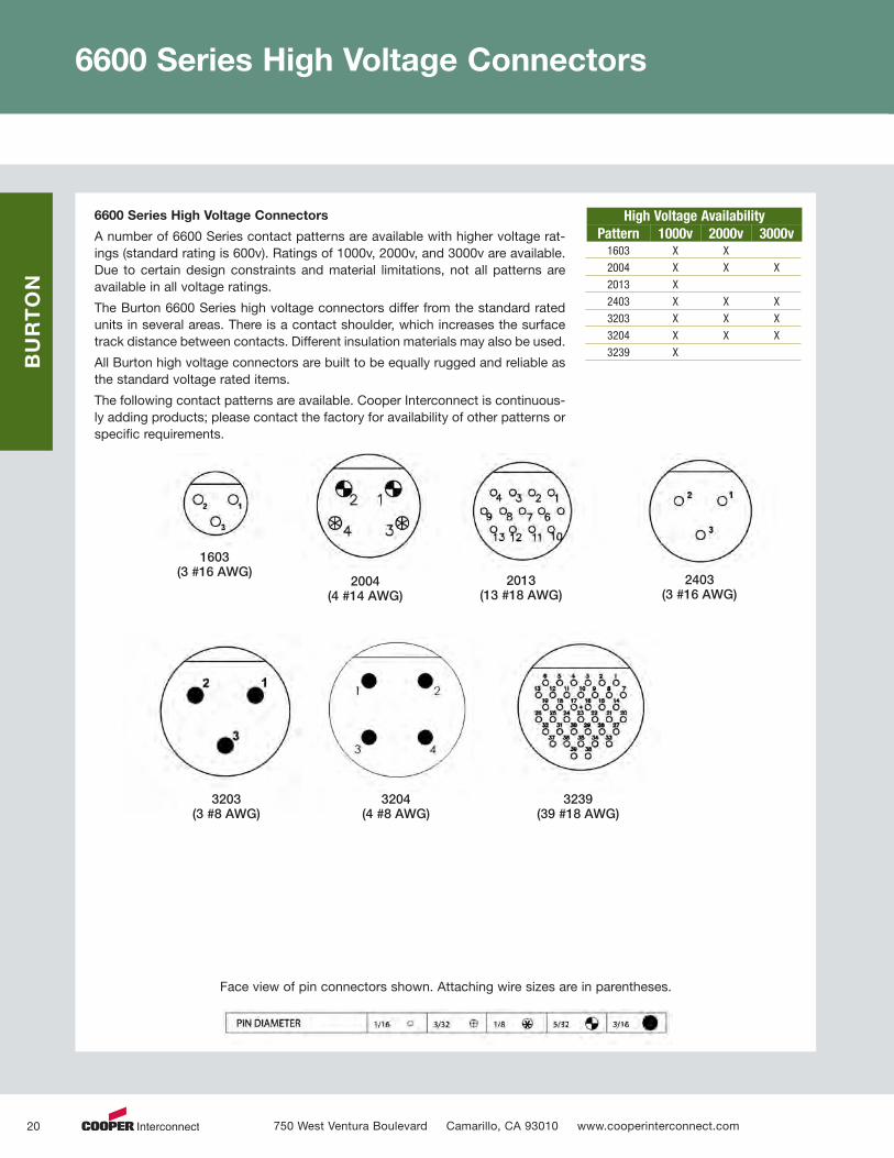
6600 Series High Voltage Connectors
6600 Series High Voltage Connectors
A number of 6600 Series contact patterns are available with higher voltage rat-ings (standard rating is 600v). Ratings of 1000v, 2000v, and 3000v are available.Due to certain design constraints and material limitations, not all patterns areavailable in all voltage ratings.
The Burton 6600 Series high voltage connectors differ from the standard ratedunits in several areas. There is a contact shoulder, which increases the surfacetrack distance between contacts. Different insulation materials may also be used.
All Burton high voltage connectors are built to be equally rugged and reliable asthe standard voltage rated items.
The following contact patterns are available. Cooper Interconnect is continuous-ly adding products; please contact the factory for availability of other patterns orspecific requirements.
High Voltage AvailabilityPattern 1000v 2000v 3000v1603 X X
2004 X X X
2013 X
2403 X X X
3203 X X X
3204 X X X
3239 X
Face view of pin connectors shown. Attaching wire sizes are in parentheses.
1603(3 #16 AWG)
2004(4 #14 AWG)
2013(13 #18 AWG)
2403(3 #16 AWG)
3203(3 #8 AWG)
3204(4 #8 AWG)
3239(39 #18 AWG)
750 West Ventura Boulevard Camarillo, CA 93010 www.cooperinterconnect.com 20
60704_Text_v9_C9599 Cooper_Subsea Cat_p1-19 3/2/12 12:50 PM Page 20
BURTON
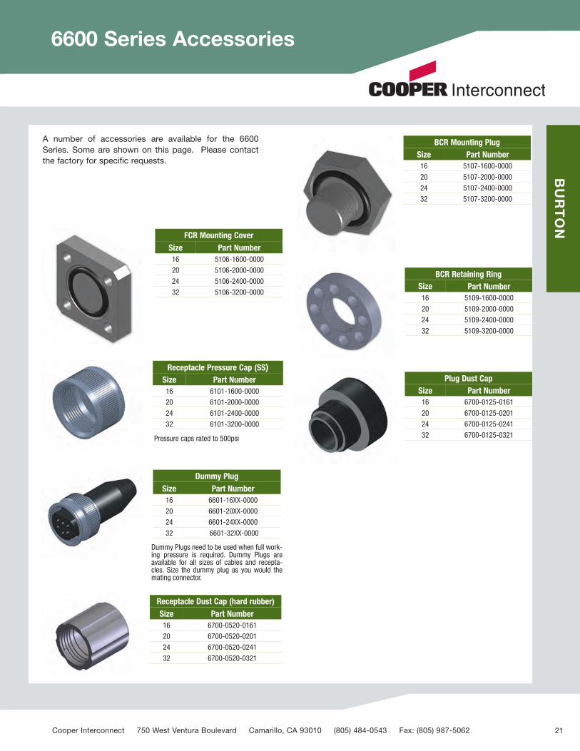
6600 Series Accessories
FCR Mounting CoverSize Part Number16 5106-1600-0000
20 5106-2000-0000
24 5106-2400-0000
32 5106-3200-0000
BCR Mounting PlugSize Part Number16 5107-1600-0000
20 5107-2000-0000
24 5107-2400-0000
32 5107-3200-0000
BCR Retaining RingSize Part Number16 5109-1600-0000
20 5109-2000-0000
24 5109-2400-0000
32 5109-3200-0000
Plug Dust CapSize Part Number16 6700-0125-0161
20 6700-0125-0201
24 6700-0125-0241
32 6700-0125-0321
Receptacle Dust Cap (hard rubber)Size Part Number16 6700-0520-0161
20 6700-0520-0201
24 6700-0520-0241
32 6700-0520-0321
Dummy PlugSize Part Number16 6601-16XX-0000
20 6601-20XX-0000
24 6601-24XX-0000
32 6601-32XX-0000
Receptacle Pressure Cap (SS)Size Part Number16 6101-1600-0000
20 6101-2000-0000
24 6101-2400-0000
32 6101-3200-0000
A number of accessories are available for the 6600Series. Some are shown on this page. Please contactthe factory for specific requests.
Dummy Plugs need to be used when full work-ing pressure is required. Dummy Plugs areavailable for all sizes of cables and recepta-cles. Size the dummy plug as you would themating connector.
Pressure caps rated to 500psi
Cooper Interconnect 750 West Ventura Boulevard Camarillo, CA 93010 (805) 484-0543 Fax: (805) 987-5062 21
60704_Text_v9_C9599 Cooper_Subsea Cat_p1-19 3/2/12 12:50 PM Page 21

BURTON
5400 Series
Part # Figure A B C D E Size O-Ring1001
A5/818NF
1.75(44.5)
1.10(27.9)
1.125(28.7)
0.50(12.7)
8 AWG
2-1161002 12 AWG
1004 16 AWG
1601
A1
14NF2.00(50.8)
1.45(36.8)
1.50(38.1)
0.50(12.7)
4 AWG
2-1221604 8 AWG
1608 14 AWG
1620 16 AWG
2401
A1-1/212NF
3.60(91.4)
1.85(47.0)
2.00(50.8)
0.50(12.7)
1/0
2-1302404 4 AWG
2410 12 AWG
2424 16 AWG
2804
B1-3/412NF
6.50(165.1)
2.75(69.9)
2.50(63.5)
1.25(31.8)
2 AWG
2-1342820 12 AWG
2832 16 AWG
The 5400 Series is an extremely ruggedand reliable underwater electrical pene-trator for pressures of up to 10,000 psi. Itshould be used in situations where elec-trical disconnection is unneeded orunwanted.
A complete Cooper Interconnect-styleconductor level water blocking systemprotects valuable pressure bottles in theevent of a catastrophic failure such asthe destruction of the penetrator face orthe cable being torn away.
Only available in the straight configura-tion. For applications requiring rightangle, please consult the factory. Specialconfigurations are available such as highvoltage, pipe threaded bulkhead mount,and flange mount
750 West Ventura Boulevard Camarillo, CA 93010 www.cooperinterconnect.com 22
60704_Text_v9_C9599 Cooper_Subsea Cat_p1-19 3/2/12 12:50 PM Page 22

BURTON
ASSY LENGTH
WIRECONNECTOR, PIN
C
CONNECTOR, SOCKET
B
A
D
E F
WIRE
ASSY LENGTH
±.003.060
1.81
.060±.003
1.81
.44
+.005-.002
.360
.37
.56
.44
.422-.002+.005
.37
.56
.44 .44
Penetrators
Single Pin Penetrators
Cooper Interconnect offers a number of models of single pinpenetrators and inline connectors. These penetrators aretypically used where space is at a premium and/or extreme-ly high pressures are expected.
The penetrators include a glass sealed contact and so mostdesigns can also withstand equal back pressure (internalpressure), partially depending on their O-Ring configuration.
Burton Single Pin DimensionsPenetrator pin OD thread hex
5002-1501-0000 0.062 1/4-28 UNF 0.3755012-1501-0000 0.093 5/16-24 UNF 0.437
Connector, pin A B C5002-0011-XXXX 0.062 0.44 1.005012-0011-XXXX 0.093 0.44 1.06
Connector, socket D E F5002-0012-XXXX 0.312 0.312 1.325012-0012-XXXX 0.375 0.375 1.43
4
1
87
32
5 686
3
7
5
2
4
1
Back Pressure (Motor) Penetrator
Some penetrator applications are subject to back pres-sure. An example is a submerged motor. Normally pres-sure balanced, an overheated motor may have higherpressure inside. Most penetrators are not capable ofhandling this condition resulting in oil or water enteringthe penetrator from the rear causing it to fail electrically.Burton has developed a line of penetrators that can han-dle this back pressure. Capacities include voltages from600v to 5kV; and ampacities over 140. Please contactthe factory with your specific requirements. The exampleabove is a 5kV, 6AWG (36 amp) motor penetrator.
Cooper Interconnect 750 West Ventura Boulevard Camarillo, CA 93010 (805) 484-0543 Fax: (805) 987-5062 23
60704_Text_v9_C9599 Cooper_Subsea Cat_p1-19 3/2/12 12:50 PM Page 23

BURTON
Ethernet and Power Cable Assemblies
Cooper Interconnect’s BurtonUnderwater Ethernet Cable Assembliesprovide power and data connections inthe harshest environments.
Just one cable assembly provides bothhigh speed (up to 1GB/SEC) Internetconnection and power (600 Volts) in asubsea environment.
Our ethernet and cable assemblies areof the highest quality to withstandharsh undersea environments. We useonly tested Burton 5500/6600 connec-tors with custom-designed cables toprovide both data and power commu-nication in the one assembly.
PERFORMANCE & FEATURES:
• 1000BaseT network performancewith power.
• Connectors and cables rated to10,000 psi.
• TIA/EIA-568-B.2.
• IEEE 802.3-2005
• Pure Ethernet available in shellsizes 15.
750 West Ventura Boulevard Camarillo, CA 93010 www.cooperinterconnect.com 24
60704_Text_v9_C9599 Cooper_Subsea Cat_p1-19 3/2/12 12:50 PM Page 24

BURTON
Ethernet and Power Cable Assemblies
The 5500 Series is an extremelyrugged and reliable underwater elec-trical connector. It is the standardCooper Interconnect Burton serieswith pins in the receptacles and sock-ets in the plugs.
The pin and socket relationship is dueto the fact that in most applications,power runs from the plug into thereceptacle. For safety reasons, it isdesirable never to have power avail-able on the pin side. For reversepower applications, refer to CooperInterconnect’s Burton 6600 series,
For over three decades, the Burton5500 Series has been the industrystandard connector for applicationswhich require reliable service insevere situations. The rugged metalshells, recessed pins and face-typeseals assure dependable service in themost demanding situations.
1 Cable
2 Conductor
3 Socket
4 Molded Body
5 Metal Shell
6 Locking Ring
7 Keyway
8 Metal Shell
9 Pin
10 Pigtails
11 Epoxy Backfill
12 Pressure Wafer
Pressure Rating 10,000 PSI
Voltage Rating 600 Volts
Performance Rating 1 GB/SEC (up to 75 meters length)
Contact High cond. copper alloy
Shell 316L SS (passivated)
Body Integrally molded elastomer
Data and Specifications
Materials
Ethernet Description
Part Number
Bulkhead Receptacle Shell Size 20, 15
5507-2013-EXXX (Power and Ethernet)5507-2021-EXXX (Power and Ethernet)
5507-1508-EXXX (Ethernet Only)
Flange Mount Receptacle Shell Size 20
5506-2013-EXXX (Power and Ethernet)5506-2021-EXXX (Power and Ethernet)
5506-1508-EXXX (Ethernet Only)
Double Ended Plug Shell Size 15 and 20
5999-1049-EXXX (Power and Ethernet)(21 Contacts and 13 Contacts5501-1508-EXXX (Single Ended)5999-XXXX-EXXX (Double Ended)
Cooper Interconnect 750 West Ventura Boulevard Camarillo, CA 93010 (805) 484-0543 Fax: (805) 987-5062 25
60704_Text_v9_C9599 Cooper_Subsea Cat_p1-19 3/2/12 12:50 PM Page 25
BURTON
Burton SC Series Overview
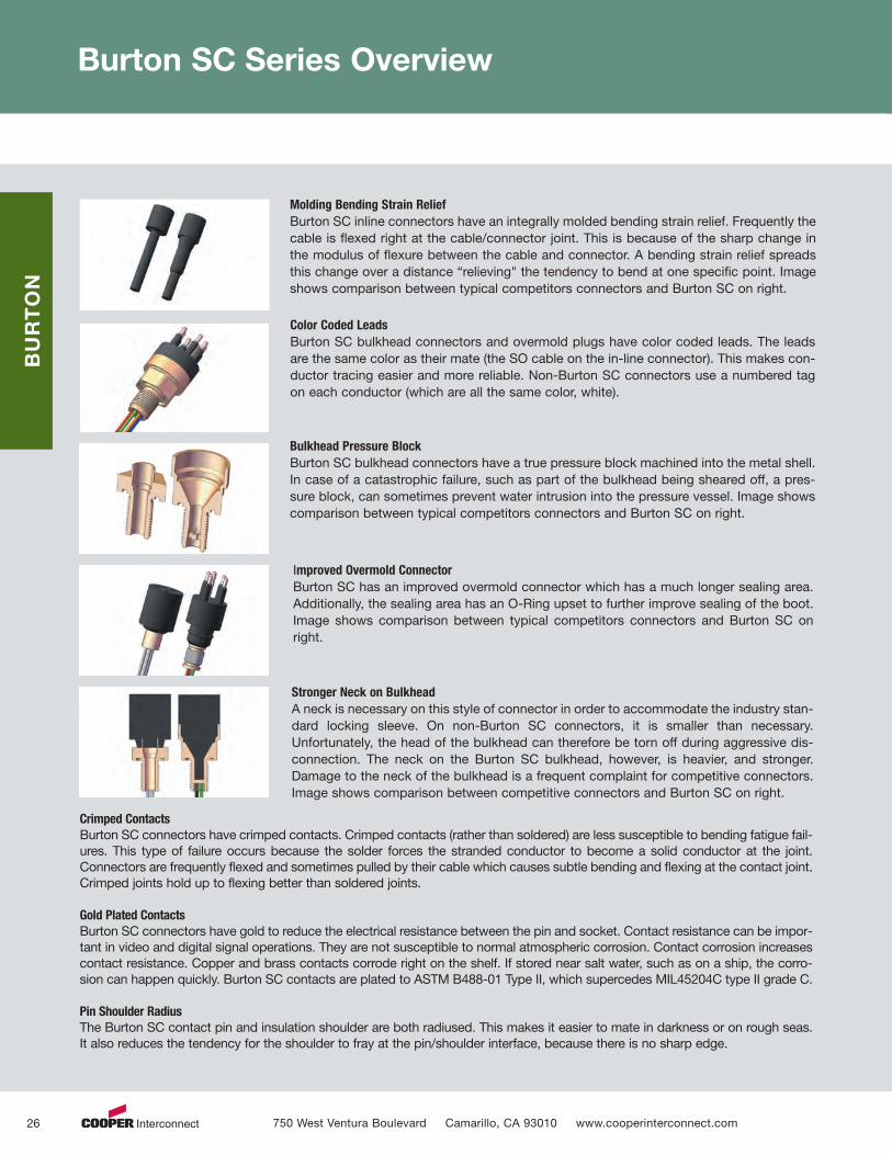
Molding Bending Strain ReliefBurton SC inline connectors have an integrally molded bending strain relief. Frequently thecable is flexed right at the cable/connector joint. This is because of the sharp change inthe modulus of flexure between the cable and connector. A bending strain relief spreadsthis change over a distance “relieving" the tendency to bend at one specific point. Imageshows comparison between typical competitors connectors and Burton SC on right.
Color Coded LeadsBurton SC bulkhead connectors and overmold plugs have color coded leads. The leadsare the same color as their mate (the SO cable on the in-line connector). This makes con-ductor tracing easier and more reliable. Non-Burton SC connectors use a numbered tagon each conductor (which are all the same color, white).
Bulkhead Pressure BlockBurton SC bulkhead connectors have a true pressure block machined into the metal shell.In case of a catastrophic failure, such as part of the bulkhead being sheared off, a pres-sure block, can sometimes prevent water intrusion into the pressure vessel. Image showscomparison between typical competitors connectors and Burton SC on right.
Improved Overmold ConnectorBurton SC has an improved overmold connector which has a much longer sealing area.Additionally, the sealing area has an O-Ring upset to further improve sealing of the boot.Image shows comparison between typical competitors connectors and Burton SC onright.
Stronger Neck on BulkheadA neck is necessary on this style of connector in order to accommodate the industry stan-dard locking sleeve. On non-Burton SC connectors, it is smaller than necessary.Unfortunately, the head of the bulkhead can therefore be torn off during aggressive dis-connection. The neck on the Burton SC bulkhead, however, is heavier, and stronger.Damage to the neck of the bulkhead is a frequent complaint for competitive connectors.Image shows comparison between competitive connectors and Burton SC on right.
Crimped ContactsBurton SC connectors have crimped contacts. Crimped contacts (rather than soldered) are less susceptible to bending fatigue fail-ures. This type of failure occurs because the solder forces the stranded conductor to become a solid conductor at the joint.Connectors are frequently flexed and sometimes pulled by their cable which causes subtle bending and flexing at the contact joint.Crimped joints hold up to flexing better than soldered joints.
Gold Plated ContactsBurton SC connectors have gold to reduce the electrical resistance between the pin and socket. Contact resistance can be impor-tant in video and digital signal operations. They are not susceptible to normal atmospheric corrosion. Contact corrosion increasescontact resistance. Copper and brass contacts corrode right on the shelf. If stored near salt water, such as on a ship, the corro-sion can happen quickly. Burton SC contacts are plated to ASTM B488-01 Type II, which supercedes MIL45204C type II grade C.
Pin Shoulder RadiusThe Burton SC contact pin and insulation shoulder are both radiused. This makes it easier to mate in darkness or on rough seas.It also reduces the tendency for the shoulder to fray at the pin/shoulder interface, because there is no sharp edge.
750 West Ventura Boulevard Camarillo, CA 93010 www.cooperinterconnect.com 26
60704_Text_v9_C9599 Cooper_Subsea Cat_p1-19 3/2/12 12:50 PM Page 26

BURTON
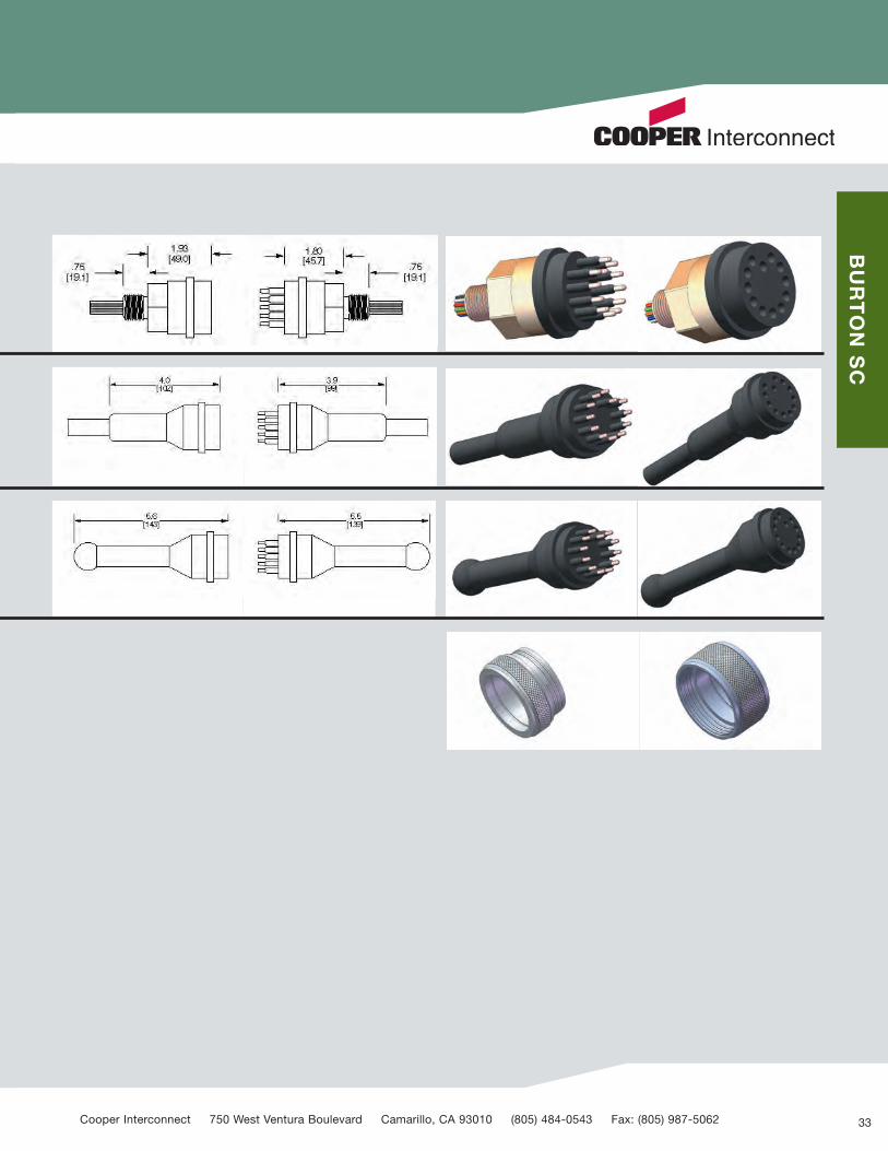
Burton SC Series Specifications
A-Size
B-SizeC-Size
CI-
Cooper Interconnect 750 West Ventura Boulevard Camarillo, CA 93010 (805) 484-0543 Fax: (805) 987-5062 27
60704_Text_v9_C9599 Cooper_Subsea Cat_p1-19 3/2/12 12:50 PM Page 27

BURTON SC
Burton SC Series: A-Size 1” (25mm) Dia.
Burton SC Series A-Size
A-Size has a 1.00 inch (25 mm) diameter form factor. It is the smallest standard size. Contact patterns available include 2, 3,4, and 5.
Bulkheads
Bulkhead connector receptacles are designed to be mounted to your pressure vessel. They are capable of handling 10,000psi pressure differential (open face). Bulkheads are available in aluminum, brass, or stainless steel. Other materials can bemade by special request.
Inlines
Inline connector plugs are available as pigtails or can be molded onto your cable. The standard pigtail length is 1 meter.However, you may specify any length. Inline connectors plug into a bulkhead receptacle or another inline connector.
PBOF
PBOF / Overmold connectors may be used as PBOF (pressure balanced oil filled) or overmolded inline connectors. There is agroove that fits standard size boots for use as an overmold type.
Overmold
Overmold connectors are for customers who have their own in-house molding capability. The customer may attach almost anytype of cable and overmold it to the connector. They have two grooves for tensile strength and a knurled area for rotationalstrength.
Dummies
Dummy connectors are used to blank off either a bulkhead receptacle, or an inline connector to prevent salt water from touch-ing the gold plated contacts.
Locking Sleeves
Locking sleeves are not necessary for the functionality of Burton SC connectors. However, some customers prefer the assur-ance that the connectors will not become disengaged by pulling on a cable.Locking sleeves are available in several differentmaterials: Delrin, Aluminum 6061, and Stainless Steel 303. We manufacture our own locking sleeves on a Mori Seiki turningcenter and so we can easily make them with other materials specified by the customer.
Standard locking sleeves are available with the traditional snap ring groove. They are very convenient for adding a lockingsleeve after a bulkhead has been installed, or anytime on a cable assembly. We have snap rings made from Stainless Steel302, and also Aluminum 6061 (mostly for use with aluminum bulkheads). Aluminum snap rings are much better in contact withaluminum bulkheads for galvanic corrosion reasons. Please see the Technical Notes page for more information about galvan-ic corrosion. Locking sleeves are also available with a shoulder instead of a snap ring.
750 West Ventura Boulevard Camarillo, CA 93010 www.cooperinterconnect.com 28
60704_Text_v9_C9599 Cooper_Subsea Cat_p1-19 3/2/12 12:50 PM Page 28

BURTON SC
Cooper Interconnect 750 West Ventura Boulevard Camarillo, CA 93010 (805) 484-0543 Fax: (805) 987-5062 29
60704_Text_v9_C9599 Cooper_Subsea Cat_p1-19 3/2/12 12:50 PM Page 29

BURTON SC
Burton SC Series: B-Size 1.25” (32mm) Dia.
Burton SC Series B-Size
B-size has a 1.25 inch (32 mm) diameter form factor. It is the intermediate standard size. Contact patterns available include 2,6, 8 and 10.
Bulkheads
Bulkhead connector receptacles are designed to be mounted to your pressure vessel. They are capable of handling 10,000psi pressure differential (open face). Bulkheads are available in aluminum, brass, or stainless steel. Other materials can bemade by special request.
Inlines
Inline connector plugs are available as pigtails or can be molded onto your cable. The standard pigtail length is 1 meter.However, you may specify any length. Inline connectors plug into a bulkhead receptacle or another inline connector.
PBOF
PBOF / Overmold connectors may be used as PBOF (pressure balanced oil filled) or overmolded inline connectors. There is agroove that fits standard size boots for use as an overmold type.
Overmold
Overmold connectors are for customers who have their own in-house molding capability. The customer may attach almost anytype of cable and overmold it to the connector. They have two grooves for tensile strength and a knurled area for rotationalstrength.
Dummies
Dummy connectors are used to blank off either a bulkhead receptacle, or an inline connector to prevent salt water from touch-ing the gold plated contacts.
Locking Sleeves
Locking sleeves are not necessary for the functionality of Burton SC connectors. However, some customers prefer the assur-ance that the connectors will not become disengaged by pulling on a cable. Locking sleeves are available in several differentmaterials: Delrin, Aluminum 6061, and Stainless Steel 303. We manufacture our own locking sleeves on a Mori Seiki turningcenter and so we can easily make them with other materials specified by the customer.
Standard locking sleeves are available with the traditional snap ring groove. They are very convenient for adding a lockingsleeve after a bulkhead has been installed, or anytime on a cable assembly. We have snap rings made from Stainless Steel302, and also Aluminum 6061 (mostly for use with aluminum bulkheads). Aluminum snap rings are much better in contact withaluminum bulkheads for galvanic corrosion reasons. Please see the Technical Notes page for more information about galvan-ic corrosion. Locking sleeves are also available with a shoulder instead of a snap ring.
750 West Ventura Boulevard Camarillo, CA 93010 www.cooperinterconnect.com 30
60704_Text_v9_C9599 Cooper_Subsea Cat_p1-19 3/2/12 12:50 PM Page 30

BURTON SC
Cooper Interconnect 750 West Ventura Boulevard Camarillo, CA 93010 (805) 484-0543 Fax: (805) 987-5062 31
60704_Text_v9_C9599 Cooper_Subsea Cat_p1-19 3/2/12 12:50 PM Page 31

BURTON SC
Burton SC Series: C-Size 1.60” (41mm) Dia.
32
Burton SC Series C-Size
C-Size has a 1.60 inch (41 mm) diameter form factor. It is the largest standard size. Contact patterns available include 12 and16.
Bulkheads
Bulkhead connector receptacles are designed to be mounted to your pressure vessel. They are capable of handling 10,000psi pressure differential (open face). Bulkheads are available in aluminum, brass, or stainless steel. Other materials can bemade by special request.
Inlines
Inline connector plugs are available as pigtails or can be molded onto your cable. The standard pigtail length is 1-meter.However, you may specify any length. Inline connectors plug into a bulkhead receptacle or another inline connector.
Dummies
Dummy connectors are used to blank off either a bulkhead receptacle, or an inline connector to prevent salt water from touch-ing the gold plated contacts.
Locking Sleeves
Locking sleeves are not necessary for the functionality of Burton SC connectors. However, some customers prefer the assur-ance that the connectors will not become disengaged by pulling on a cable.Locking sleeves are available in several differentmaterials: Delrin, Aluminum 6061, and Stainless Steel 303. We manufacture our own locking sleeves on a Mori Seiki turningcenter and so we can easily make them with other materials specified by the customer.
Standard locking sleeves are available with the traditional snap ring groove. They are very convenient for adding a lockingsleeve after a bulkhead has been installed, or anytime on a cable assembly. We have snap rings made from Stainless Steel302, and also Aluminum 6061 (mostly for use with aluminum bulkheads). Aluminum snap rings are much better in contact withaluminum bulkheads for galvanic corrosion reasons. Please see the Technical Notes page for more information about galvan-ic corrosion. Locking sleeves are also available with a shoulder instead of a snap ring.
750 West Ventura Boulevard Camarillo, CA 93010 www.cooperinterconnect.com
60704_Text_v9_C9599 Cooper_Subsea Cat_p1-19 3/2/12 12:50 PM Page 32
BURTON SC
33Cooper Interconnect 750 West Ventura Boulevard Camarillo, CA 93010 (805) 484-0543 Fax: (805) 987-5062
60704_Text_v9_C9599 Cooper_Subsea Cat_p1-19 3/2/12 12:50 PM Page 33

Series 51 Male Connector–“Underwater Pluggable”
34
FEATURES:
• Exclusive construction of thesepatented WATERMATE™ electricalconnectors permits underwaterplugging and unplugging with elec-trical power de-energized.
• Pressure rated up to 20,000 psi ormaximum 45,000 feet of sea water(except Series 53 which is rated upto 10,000 psi).
• Pressure balanced for easy engage-ment and disengagement in high-pressure environments.
ELECTRO OCEANIC
Model No. ofContacts
No. ofPins
MaxVolts
ContactsPer Pin
RatingAmps1
Wire Size AWG
AIn.
BIn.
DIn.
L ±1In.
Mates With Model2
51E1M-1 1 1 230 1 15 16 .44 1.0 2.0 24 51E1F, 53E1F, 59E1F, Series 54 & 84 J Box
51E1M-80 1 1 230 1 15 16 .63 1.56 2.56 24 51E1F, 53E1F, 59E1F, Series 54 & 84 J Box
51H1M-1 1 1 440 1 60 8 1.0 1.5 3.5 36 51H1F, 53H1F, Series 54J Box
51E2M-1 2 2 230 1 15 16 1.0 .75 1.75 24 51E2F, 53E2F, Series 54J Box
51F2M-1 2 1 115 2 7.5 18 .44 1.0 2.0 24 51F2F, 53F2F, 59F2F, Series 54 & 84 J Box
51F2M-50 2 1 115 2 7.5 18 .63 1.56 2.56 24 51F2F, 53F2F, 59F2F, Series 54 & 84 J Box
51E3M-1 3 3 230 1 15 16 1.0 .75 1.75 24 51E3F, 53E3F, Series 54J Box
51H3M-1 3 3 440 1 60 6 2.0 1.50 3.50 36 51H3F, 53H3F, Series 54J Box
51L3M-1 3 3 440 1 100 4 2.5 2.0 4.38 36 51L3F, 53L3F, Series 54J Box
51E4M-1 4 4 230 1 15 16 1.25 .75 1.75 24 51E4F, 53E4F, Series 54J Box
51F4M-1 4 2 115 2 7.5 18 1.0 .75 1.75 24 51F4F, 53F4F, Series 54J Box
51H4M-1 4 4 440 1 60 6 2.0 1.5 3.5 36 51H4F, 53H4F, Series 54J Box
51L4M-1 4 4 440 1 85 4 2.5 2.0 4.38 36 51L4F, 53L4F, Series 54J Box
51F6M-1 6 3 115 2 7.5 18 1.25 .75 1.75 36 51F6F, 53F6F, Series 54J Box
51F8M-1 8 4 115 2 7.5 18 1.25 .75 1.75 36 51F8F, 53F8F, Series 54J Box
Unless otherwise specified dimensions are nominal.1 Per contact.2 Add DO for dummy connector, all circuits open.Add DS for dummy connector, all circuits shorted or paired as indicated.
750 West Ventura Boulevard Camarillo, CA 93010 www.cooperinterconnect.com
60704_Text_v9_C9599 Cooper_Subsea Cat_p1-19 3/2/12 12:51 PM Page 34
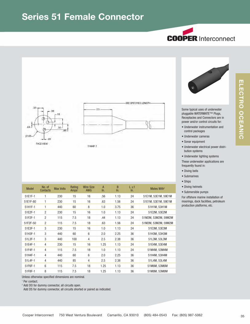
Series 51 Female Connector
35
ELECTRO OCEANIC
Some typical uses of underwater pluggable WATERMATE™ Plugs,Receptacles and Connectors are inpower and/or control circuits for:
• Underwater instrumentation andcontrol packages
• Underwater cameras
• Sonar equipment
• Underwater electrical power distri-bution systems
• Underwater lighting systems
These underwater applications arefrequently found in:
• Diving bells
• Submarines
• Ships
• Diving helmets
• Submersible pumps
For offshore marine installation ofmoorings, dock facilities, petroleumproduction platforms, etc.
Model No. ofContacts Max Volts Rating
Amps1Wire SizeAWG
AIn.
BIn.
L ±1In. Mates With2
51E1F-1 1 230 15 16 .56 1.13 24 51E1M, 53E1M, 59E1M
51E1F-80 1 230 15 16 .63 1.56 24 51E1M, 53E1M, 59E1M
51H1F-1 1 440 60 8 1.0 3.75 36 51H1M, 53H1M
51E2F-1 2 230 15 16 1.0 1.13 24 51E2M, 53E2M
51F2F-1 2 115 7.5 18 .44 1.13 24 51M2M, 53M2M, 59M2M
51F2F-50 2 115 7.5 18 .63 1.56 24 51M2M, 53M2M, 59M2M
51E3F-1 3 230 15 16 1.0 1.13 24 51E3M, 53E3M
51H3F-1 3 440 60 6 2.0 2.25 36 51H3M, 53H3M
51L3F-1 3 440 100 4 2.5 2.38 36 51L3M, 53L3M
51E4F-1 4 230 15 16 1.25 1.13 24 51E4M, 53E4M
51F4F-1 4 115 7.5 18 1.0 1.13 24 51M4M, 53M4M
51H4F-1 4 440 60 6 2.0 2.25 36 51H4M, 53H4M
51L4F-1 4 440 85 4 2.5 2.38 36 51L4M, 53L4M
51F6F-1 6 115 7.5 18 1.25 1.13 36 51M6M, 53M6M
51F8F-1 8 115 7.5 18 1.25 1.13 36 51M8M, 53M8M
Unless otherwise specified dimensions are nominal.1 Per contact.2 Add DO for dummy connector, all circuits open. Add DS for dummy connector, all circuits shorted or paired as indicated.
Cooper Interconnect 750 West Ventura Boulevard Camarillo, CA 93010 (805) 484-0543 Fax: (805) 987-5062
60704_Text_v9_C9599 Cooper_Subsea Cat_p1-19 3/2/12 12:51 PM Page 35

Series B51 Male Connector–“Underwater Pluggable”
36
FEATURES: • Exclusive construction of thesepatented WATERMATE™ electricalconnectors permits underwaterplugging and unplugging with electrical power de-energized.
• Pressure rated up to 20,000 psi ormaximum 45,000 feet of sea water(except Series 53 which is rated upto 10,000 psi).
• Pressure balanced for easy engagement and disengagement in high-pressure environments.
Model No. ofContacts
No. ofPins
MaxVolts
WireSizeAWG
RatingAmps1
ADia.
BDia. C D E F L ±1
In. Mates With2
B51E1M-1 1 1 230 16 15 .63 .83 .25 1.19 2.50 3.50 36 B51E1F-1,B53E1F-1
B51L1M-1 1 1 440 16 175 1.25 1.45 .25 1.19 1.50 3.87 36 B51L1F-1,B53L1F-1
B51E2M-1 2 2 230 16 15 1.00 1.20 .25 1.19 2.50 3.50 36 B51E2F-1,B53E2F-1
B51F2M-1 2 1 115 18 7.5 .63 .83 .25 1.19 2.50 3.50 36 B51F2F-1,B53F2F-1
B51E3M-1 3 3 230 16 15 1.00 1.20 .25 1.19 2.50 3.50 36 B51E3F-1,B53E3F-1
B51L3M-1 3 3 440 4 100 2.50 3.00 .38 1.88 3.50 6.37 36 B51L3F-1,B53L3F-1
B51E4M-1 4 4 230 16 15 1.25 1.45 .25 1.19 2.50 3.50 36 B51E4F-1,B53E4F-1
B51F4M-1 4 2 115 18 7.5 1.00 1.20 .25 1.19 2.50 3.50 36 B51F4F-1,B53F4F-1
B51H4M-1 4 4 440 4 100 2.50 3.00 .38 1.88 3.50 6.37 36 B51L4F-1,B53L4F-1
B51F6M-1 6 3 115 18 7.5 1.25 1.45 .25 1.19 2.50 3.50 36 B51F6F-1,B53F6F-1
B51F8M-1 8 4 115 18 7.5 1.25 1.45 .25 1.19 2.50 3.50 36 B51F8F-1,B53F8F-1
Unless otherwise specified dimensions are nominal.1 For DO and DS dummy connectors, see 51 Series, pages 34 & 35.2 Per contact.
750 West Ventura Boulevard Camarillo, CA 93010 www.cooperinterconnect.com
ELECTRO OCEANIC
60704_Text_v9_C9599 Cooper_Subsea Cat_p1-19 3/2/12 12:51 PM Page 36

Series B51 Female Connector
37
Some typical uses of underwater pluggable WATERMATE™ Plugs,Receptacles and Connectors are inpower and/or control circuits for:
• Underwater instrumentation andcontrol packages
• Underwater cameras
• Sonar equipment
• Underwater electrical power distribution systems
• Underwater lighting systems
These underwater applications arefrequently found in:
• Diving bells
• Submarines
• Ships
• Diving helmets
• Submersible pumps
For offshore marine installation ofmoorings, dock facilities, petroleumproduction platforms, etc.
Model No. ofContacts
No. ofPins Max VoltsWire SizeAWG
RatingAmps1
ADia.
BDia. C D E L ±1
In. Mates With2
B51E1F-1 1 1 230 16 15 .63 .83 .25 1.19 2.50 36 B51E1M-1,B53E1M-1
B51L1F-1 1 1 440 16 175 1.25 1.45 .25 1.19 4.13 36 B51L1M-1,B53L1M-1
B51E2F-1 2 2 230 16 15 1.00 1.20 .25 1.19 2.50 36 B51E2M-1,B53E2M-1
B51F2F-1 2 1 115 18 7.5 .63 .83 .25 1.19 2.50 36 B51F2M-1,B53F2M-1
B51E3F-1 3 3 230 16 15 1.00 1.20 .25 1.19 2.50 36 B51E3M-1,B53E3M-1
B51L3F-1 3 3 440 4 100 2.50 3.00 .38 2.75 5.00 36 B51L3M-1,B53L3M-1
B51E4F-1 4 4 230 16 15 1.25 1.45 .25 1.19 2.50 36 B51E4M-1,B53E4M-1
B51F4F-1 4 2 115 18 7.5 1.00 1.20 .25 1.19 2.50 36 B51F4M-1,B53F4M-1
B51H4F-1 4 4 440 4 100 2.50 3.00 .38 2.75 5.00 36 B51L4M-1,B53L4M-1
B51F6F-1 6 3 115 18 7.5 1.25 1.45 .25 1.19 2.50 36 B51F6M-1,B53F6M-1
B51F8F-1 8 4 115 18 7.5 1.25 1.45 .25 1.19 2.50 36 B51F8M-1,B53F8M-1
Unless otherwise specified dimensions are nominal.1 For DO and DS dummy connectors, see 51 Series, pages 34 & 35.2 Per contact.
Cooper Interconnect 750 West Ventura Boulevard Camarillo, CA 93010 (805) 484-0543 Fax: (805) 987-5062
ELECTRO OCEANIC
60704_Text_v9_C9599 Cooper_Subsea Cat_p1-19 3/2/12 12:51 PM Page 37

Series 53 Male Connector
FEATURES:
• Exclusive construction of thesepatented WATERMATE™ electricalconnectors permits underwaterplugging and unplugging with electrical power de-energized.
• Pressure rated up to 20,000 psi ormaximum 45,000 feet of sea water(except Series 53 which is rated upto 10,000 psi).
• Pressure balanced for easy engagement and disengagement in high-pressure environments.
Model No. of Contacts
No. of Pins
Max Volts
ContactsPerPin
Wire SizeAWG
Rating Amps1
AIn.
BIn.
CIn.
DIn. E F L ±1
In. NP
±1/32In.
MatesWith2
53E1M-1 1 1 230 1 16 15 .63 .63 1.13 2.13 7/16-20 2-014 12 .75 .50 51E1F
53H1M-1 1 1 440 1 8 60 1.00 1.81 2.38 4.38 3/4-16 2-019 12 1.13 .75 51H1F
53E2M-1 2 2 230 1 16 15 1.00 1.13 1.63 2.63 7/16-20 2-014 12 .75 .50 51E2F
53F2M-1 2 1 115 2 18 7.5 .63 .63 1.13 2.13 7/16-20 2-014 12 .75 .50 51F2F
53E3M-1 3 3 230 1 16 15 1.00 1.13 1.63 2.63 7/16-20 2-014 12 .75 .50 51E3F
53H3M-1 3 3 440 1 8 60 2.00 2.50 3.13 5.13 1-1/4-12 2-125 12 1.75 1.25 51H3F
53L3M-1 3 3 440 1 4 100 2.50 3.38 3.88 6.25 1-3/4-12 2-136 12 2.50 1.50 51L3F
53E4M-1 4 4 230 1 16 15 1.25 1.13 1.63 2.63 1/2-20 2-015 12 .88 .50 51E4F
53F4M-1 4 2 115 2 18 7.5 1.00 1.13 1.63 2.63 7/16-20 2-014 12 .75 .50 51F4F
53H4M-1 4 4 440 1 8 60 2.00 2.50 3.13 5.13 1-1/4-12 2-125 12 1.75 1.25 51H4F
53L4M-1 4 4 440 1 4 100 2.50 3.38 3.88 6.25 1-3/4-12 2-136 12 2.50 1.50 51L4F
53F6M-1 6 3 115 2 18 7.5 1.25 1.13 1.63 2.63 1/2-20 2-015 12 .88 .50 51F6F
53F8M-1 8 4 115 2 18 7.5 1.25 1.13 1.63 2.63 1/2-20 2-015 12 .88 .50 51F8F
Unless otherwise specified dimensions are nominal.1 Per contact.2 For DO and DS dummy connectors, see 51 Series, page 34 & 35.
Bulkhead connectors must be installed with pigtails on low-pressure side of bulkheads or interior of vessels. Pressure on pigtail side must not exceed the pressure on external side of connector.
750 West Ventura Boulevard Camarillo, CA 93010 www.cooperinterconnect.com 38
ELECTRO OCEANIC
60704_Text_v9_C9599 Cooper_Subsea Cat_p1-19 3/2/12 12:51 PM Page 38

Series 53 Female Connector
Some typical uses of underwater pluggable WATERMATE™ Plugs,Receptacles and Connectors are inpower and/or control circuits for:
• Underwater instrumentation andcontrol packages
• Underwater cameras
• Sonar equipment
• Underwater electrical power distribution systems
• Underwater lighting systems
These underwater applications arefrequently found in:
• Diving bells
• Submarines
• Ships
• Diving helmets
• Submersible pumps
For offshore marine installation ofmoorings, dock facilities, petroleumproduction platforms, etc.
ModelNo. of
Contacts
Max Volts
Wire SizeAWG
Rating Amps
AIn.
BIn.
CIn. E F L ±1
In. NP
±1/32In.
MatesWith
53E1F-1 1 230 16 15 .63 1.50 2.00 7/16-20 2-014 12 .75 .50 51E1M
53H1F-1 1 440 8 60 1.00 2.94 3.50 3/4-16 2-019 12 1.13 .75 51H1M
53E2F-1 2 230 16 15 1.00 1.13 1.75 7/16-20 2-014 12 .75 .50 51E2M
53F2F-1 2 115 18 7.5 .63 1.50 2.00 7/16-20 2-014 12 .75 .50 51F2M
53E3F-1 3 230 16 15 1.00 1.13 1.75 7/16-20 2-014 12 .75 .50 51E3M
53H3F-1 3 440 8 60 2.00 2.38 3.00 1-1/4-12 2-125 12 1.75 1.25 51H3M
53L3F-1 3 440 4 100 2.50 3.38 3.88 1-3/4-12 2-136 12 2.50 1.50 51L3M
53E4F-1 4 230 16 15 1.25 1.13 2.00 1/2-20 2-015 12 .88 .50 51E4M
53F4F-1 4 115 18 7.5 1.00 1.13 1.75 7/16-20 2-014 12 .75 .50 51F4M
53H4F-1 4 440 8 60 2.00 2.38 3.00 1-1/4-12 2-125 12 1.75 1.25 51H4M
53L4F-1 4 440 4 100 2.50 3.38 3.88 1-3/4-12 2-136 12 2.50 1.50 51L4M
53F6F-1 6 115 18 7.5 1.25 1.13 2.00 1/2-20 2-015 12 .88 .50 51M6M
53F8F-1 8 115 18 7.5 1.25 1.13 2.00 1/2-20 2-015 12 .88 .50 51M8M
Unless otherwise specified dimensions are nominal.1 Per contact.2 For DO and DS dummy connectors, see 51 Series, page 34 & 35.
Bulkhead connectors must be installed with pigtails on low-pressure side of bulkheads or interior of vessels. Pressure on pigtail side must not exceed the pressure on external side of connector.
Cooper Interconnect 750 West Ventura Boulevard Camarillo, CA 93010 (805) 484-0543 Fax: (805) 987-5062 39
ELECTRO OCEANIC
60704_Text_v9_C9599 Cooper_Subsea Cat_p1-19 3/2/12 12:51 PM Page 39

Series B53 Male Connector
FEATURES:
• Exclusive construction of thesepatented WATERMATE™ electricalconnectors permits underwaterplugging and unplugging with elec-trical power de-energized.
• Pressure rated up to 20,000 psi ormaximum 45,000 feet of sea water(except Series 53 which is rated upto 10,000 psi).
• Pressure balanced for easy engagement and disengagement in high-pressure environments.
ModelNo. of
Contacts
No.ofPins
Max Volts
WireSizeAWG
Rating Amps2
AIn.
BIn.
CIn.
DIn. E F O L ±1
In. P T N Mates With1
B53E1M-1 1 1 230 16 15 .63 .83 .25 1.19 2.00 3.00 2-015 12 .50 1/2-20UNF .88 B51E1F-1
B53L1M-1 1 1 440 1 175 1.25 1.45 .25 1.19 2.50 4.88 2-122 12 1.00 1-14UNF 1.50 B51H1F-1
B53E2M-1 2 2 230 16 15 1.00 1.20 .25 1.19 2.00 3.00 2-015 12 .50 1/2-20UNF .88 B51E2F-1
B53F2M-1 2 1 115 18 7.5 .63 .83 .25 1.19 2.00 3.00 2-015 12 .50 1/2-20UNF .88 B51F2F-1
B53E3M-1 3 3 230 16 15 1.00 1.20 .25 1.19 2.00 3.00 2-015 12 .50 1/2-20UNF .88 B51E3F-1
B53L3M-1 3 3 440 4 100 2.50 3.00 .38 1.88 5.00 6.38 2-136 12 1.50 1-3/4-12 UNF 2.50 B51L3F-1
B53E4M-1 4 4 230 16 15 1.25 1.45 .25 1.19 2.00 3.00 2-019 12 .75 3/4-16UNF 1.13 B51E4F-1
B53F4M-1 4 2 115 18 7.5 1.00 1.20 .25 1.19 2.00 3.00 2-015 12 .50 1/2-20UNF .88 B51F4F-1
B53L4M-1 4 4 440 4 100 2.50 3.00 .38 1.88 5.00 6.38 2-136 12 1.50 1-3/4-12 UNF 2.50 B51L4F-1
B53F6M-1 6 3 115 18 7.5 1.25 1.45 .25 1.19 2.00 3.00 2-019 12 .75 3/4-16UNF 1.13 B51F6F-1
B53F8M-1 8 4 115 18 7.5 1.25 1.45 .25 1.19 2.00 3.00 2-019 12 .75 3/4-16UNF 1.13 B51F8F-1
Unless otherwise specified dimensions are nominal.1 For DO and DS dummy connectors, see 51 Series, page 34 & 35.2 Per contact.
750 West Ventura Boulevard Camarillo, CA 93010 www.cooperinterconnect.com 40
ELECTRO OCEANIC
60704_Text_v9_C9599 Cooper_Subsea Cat_p1-19 3/2/12 12:51 PM Page 40

Series B53 Female Connector
Some typical uses of underwater pluggable WATERMATE™ Plugs,Receptacles and Connectors are inpower and/or control circuits for:
• Underwater instrumentation andcontrol packages
• Underwater cameras
• Sonar equipment
• Underwater electrical power distribution systems
• Underwater lighting systems
These underwater applications arefrequently found in:
• Diving bells
• Submarines
• Ships
• Diving helmets
• Submersible pumps
For offshore marine installation ofmoorings, dock facilities, petroleumproduction platforms, etc.
ModelNo. of
Contacts
Max Volts
Wire SizeAWG
Rating Amps
AIn.
BIn.
CIn.
DIn. E O L ±1
In. P T N Mates With
B53E1F-1 1 230 16 15 .63 .83 .25 1.19 2.31 2-015 12 .50 1/2-20UNF .88 B51E1M-1
B53L1F-1 1 440 1 175 1.25 1.95 .25 1.19 5.13 2-122 12 1.00 1-14UNF 1.50 B51H1M-1
B53E2F-1 2 230 16 15 1.00 1.20 .25 1.19 2.31 2-015 12 .50 1/2-20UNF .88 B51E2M-1
B53F2F-1 2 115 18 7.5 .63 .83 .25 1.19 2.31 2-015 12 .50 1/2-20UNF .88 B51F2M-1
B53E3F-1 3 230 16 15 1.00 1.20 .25 1.19 2.31 2-015 12 .50 1/2-20UNF .88 B51E3M-1
B53L3F-1 3 440 4 100 2.50 3.00 .38 2.75 6.50 2-136 12 1.50 1-3/4-12 UNF 2.50 B51L3M-1
B53E4F-1 4 230 16 15 1.25 1.45 .25 1.19 2.31 2-019 12 .75 3/4-16UNF 1.13 B51E4M-1
B53F4F-1 4 115 18 7.5 1.00 1.20 .25 1.19 2.31 2-015 12 .50 1/2-20UNF .88 B51F4M-1
B53L4F-1 4 440 4 100 2.50 3.00 .38 1.88 5.00 2-136 12 1.50 1-3/4-12 UNF 2.50 B51L4M-1
B53F6F-1 6 115 18 7.5 1.25 1.45 .25 1.19 2.31 2-019 12 .75 3/4-16UNF 1.13 B51F6M-1
B53F8F-1 8 115 18 7.5 1.25 1.45 .25 1.19 2.31 2-019 12 .75 3/4-16UNF 1.13 B51F8M-1
Unless otherwise specified dimensions are nominal.1 For DO and DS dummy connectors, see 51 Series, page 34 & 35.2 Per contact.
Cooper Interconnect 750 West Ventura Boulevard Camarillo, CA 93010 (805) 484-0543 Fax: (805) 987-5062 41
ELECTRO OCEANIC
60704_Text_v9_C9599 Cooper_Subsea Cat_p1-19 3/2/12 12:51 PM Page 41

Series 59 Pin Male/Female Right Angle Connectors
FEATURES: • Series 59 right angle receptacles are designed for bulkhead mountingwhere space is limited. Exclusiveconstruction of these patentedWATERMATE™ electrical connectorspermits underwater plugging andunplugging with electrical power de-energized.
• Pressure rated up to 10,000 psi or maximum 22,000 feet of seawater. (Optional to 20,000 psi)
• Pressure balanced for easy engagement and disengagement in high-pressure environments.
• Body is specially formulated neoprene rubber. Contacts are beryllium copper.
• Electrical specification similar to Series 51 and 53.
Some typical uses of underwater pluggable WATERMATE™ Plugs,Receptacles and Connectors are inpower and/or control circuits for:
• Underwater instrumentation andcontrol packages
• Underwater cameras
• Sonar equipment
• Underwater electrical power distribution systems
• Underwater lighting systems
These underwater applications arefrequently found in:
• Diving bells
• Submarines
• Ships
• Diving helmets
• Submersible pumps
For offshore marine installation ofmoorings, dock facilities, petroleumproduction platforms, etc.
Model No.of
Circuits
No. of Pins orSockets
MaxVolts
Pin orSocketDia.Inches
CircuitsPer Pin or Socket
Amps perConnector(Max.)
WireSizeAWG
P±1/32In.
BIn.
DIn.
EThread
MatesWith Shell1
59F2M or F-1 2 1 115 .188 2 7.5 18 .50 .81 1.81 3/8-24 51F2F or M
59F2M or F-2 2 1 115 .188 2 7.5 18 .75 .81 1.81 3/8-24 51F2F or M
59F2M or F-3 2 1 115 .188 2 7.5 18 1.0 .81 1.81 3/8-24 51F2F or M
59F2M or F-4 2 1 115 .188 2 7.5 18 .50 .81 1.81 7/16-20 51F2F or M
59F2M or F-5 2 1 115 .188 2 7.5 18 .75 .81 1.81 7/16-20 51F2F or M
59F2M or F-6 2 1 115 .188 2 7.5 18 1.0 .81 1.81 7/16-20 51F2F or M
Unless otherwise specified dimensions are nominal.1 Physical dimensions for 59E1F or 59E1M-1 thru 6 are the same as those listed above for – 1 through 6. Electrical ratings for 59E Series are listed on page 35.
750 West Ventura Boulevard Camarillo, CA 93010 www.cooperinterconnect.com 42
ELECTRO OCEANIC
60704_Text_v9_C9599 Cooper_Subsea Cat_p1-19 3/2/12 12:51 PM Page 42

Series 510 Two Pin Connector
FEATURES: • Series 510 right angle receptacles are designed for bulkhead mountingwhere space is limited. Exclusive con-struction of these patented WATER-MATE™ electrical connectors permitsunderwater plugging and unpluggingwith electrical power de-energized.
• Pressure rated up to 5,000 psi orequivalent to maximum 11,000 feetof seawater. (Optionally available to20,000 psi)
• Pressure balanced for easy engage-ment and disengagement in high-pressure environments.
• Body is specially formulated neoprenerubber. Contacts are beryllium copper.
• Longer shanks (P) and pigtail (L)lengths are optionally available.
• Electrical specification similar toSeries 51 and 53.
Some typical uses of underwater pluggable WATERMATE™ Plugs,Receptacles and Connectors are inpower and/or control circuits for:
• Underwater instrumentation andcontrol packages
• Underwater cameras
• Sonar equipment
• Underwater electrical power distribution systems
• Underwater lighting systems
These underwater applications arefrequently found in:
• Diving bells
• Submarines
• Ships
• Diving helmets
• Submersible pumps
For offshore marine installation ofmoorings, dock facilities, petroleumproduction platforms, etc.
Unless otherwise specified dimensions are nominal.
ModelNo. of
Circuits
No. of Pins or Sockets Max
Volts
Circuits Per Pin orSocket
Amps perConnector(Max.)
WireSizeAWG
P±1/32In.
LIn.
EThread
MatesWith Model No. of
CircuitsM U F
510E2Mor F orU-4
2 1 1/1 1 230 1 15 16 .50 12 7/16-20
52E2F orM or U-1
510E2Mor F or U-4
2
510E2Mor F or U-5
2 1 1/1 1 230 1 15 16 .75 12 7/16-20
52E2F orM or U-1
510E2Mor F or U-5
2
510E2Mor F or U-6
2 1 1/1 1 230 1 15 16 1.0 12 7/16-20
52E2F orM orU-1
510E2Mor F or U-6
2
510F4Mor F or U-4
4 1 1/1 1 115 2 7.5 18 .50 12 7/16-20
52F4F orM or U-1
510F4Mor F or U-4
4
510F4Mor F or U-5
4 1 1/1 1 115 2 7.5 18 .75 12 7/16-20
52F4F orM or U-1
510F4Mor F or U-5
4
510F4Mor F or U-6
4 1 1/1 1 115 2 7.5 18 1.0 12 7/16-20
52F4F orM or U-1
510F4Mor F or U-6
4
Cooper Interconnect 750 West Ventura Boulevard Camarillo, CA 93010 (805) 484-0543 Fax: (805) 987-5062 43
ELECTRO OCEANIC
60704_Text_v9_C9599 Cooper_Subsea Cat_p1-19 3/2/12 12:51 PM Page 43

Series 52 Two Pin Male/Female/Universal Connector
FEATURES: • Exclusive construction of thesepatented WATERMATE™ electricalconnectors permits underwaterplugging and unplugging with electrical power de-energized.
• Pressure rated up to 20,000 psi orequivalent to maximum 45,000 feetof seawater.
• Pressure balanced for easy engagement and disengagement in high pressure.
• Body is specially formulated neoprene rubber. Contacts are beryllium copper.
• Electrical specification similar toSeries 51 and 53.
Some typical uses of underwater pluggable WATERMATE™ Plugs,Receptacles and Connectors are inpower and/or control circuits for:
• Underwater instrumentation andcontrol packages
• Underwater cameras
• Sonar equipment
• Underwater electrical power distribution systems
• Underwater lighting systems
These underwater applications arefrequently found in:
• Diving bells
• Submarines
• Ships
• Diving helmets
• Submersible pumps
For offshore marine installation ofmoorings, dock facilities, petroleumproduction platforms, etc.
Unless otherwise specified dimensions are nominal.
Model No. ofCircuits
No. of Pins or Sockets Max
Volts
Circuits Per Pin orSocket
Amps perConnector(Max.)
WireSizeAWG
DIn.
L ±1In. Mates With
M U F
52E2M orF or U-1 2 2 2/2 2 230 1 15 16 2.50 24 52E2F or M or U,
510E2F or M or U
52F4M orF or U-1 4 2 2/2 2 115 2 7.5 18 2.50 24 52E4F or M or U,
510E4F or M or U
750 West Ventura Boulevard Camarillo, CA 93010 www.cooperinterconnect.com 44
ELECTRO OCEANIC
60704_Text_v9_C9599 Cooper_Subsea Cat_p1-19 3/2/12 12:51 PM Page 44

Series 610 Waterproof Switches
Magnetically operated switches aredesigned for resistance to water andoily environments.
Connection is made through an underwater pluggable connector.Operation is by remote magnet.
APPLICATIONS• Water-current meter: activating magnet mounts to propeller blade.
• Valve-position indicator: activatingmagnet, mounted on valve, triggersswitch.
• Mechanical-movement monitoring;activating magnet mounts on moving machinery.
The magnetically operated switchassembly, Catalog Number 610F2F-1,includes:
• Exclusive construction of the patent-ed WATERMATE™ electrical connec-tor permits underwater plugging andunplugging with electrical power de-energized.
• Pressure rated up to 5,000 psi orequivalent to maximum 11,000 feetof seawater.
• Pressure balanced for easy engagement and disengagement in high-pressure environments.
• Body is specially formulated neoprene rubber. Contacts are beryllium copper.
Unless otherwise specified dimensions are nominal.
Model Contact Rating
MaxAmps Max Volts
MaxContact
Resistance
VoltageBreakdown Mates With
610F2F-1 Brass 10 w dc 0.5 200 0.100 ohm 400 vdc 51F2M
610F2F-L1 Stainless Steel 10 w dc 0.5 200 0.100 ohm 400 vdc 51F2M
SWITCH
Contact arrangement: SPST-NOContact material: Rhodium Standard
ENCLOSURE
Internal construction: Switch potted in Micarta base block, screw attached to brassmounting stud.
Stud mounting: 3/8” – 24, 1/2” long with 3/8”washer and 3/8” –24 hex nut.
Enclosure: Specially formulated neoprenerubber, nonwetting surface.
Insulation resistance: 100 megohms contact-to-contact in water.
SWITCH ELECTRICAL SPECIFICATIONS
Insulation resistance: 100 megohms.
Life expectance: 10 x 106, full rating.
Contact rating: 10 w dc, 0.5 amp max.
Actuating time: 1 millisecond.
Contact bounce: 1 millisecond.
Actuating rate: Depending on drive can follow up to 400 cycles per second.
CONSTRUCTION DETAILS
Mates with Single Pin 51F2Mseries connector.
Cooper Interconnect 750 West Ventura Boulevard Camarillo, CA 93010 (805) 484-0543 Fax: (805) 987-5062 45
ELECTRO OCEANIC
60704_Text_v9_C9599 Cooper_Subsea Cat_p1-19 3/2/12 12:51 PM Page 45

Series 41 Penetrators
APPLICATIONSThe Series 41 Penetrators are suitablewhere a watertight electrical penetra-tion is required through a bulkhead.
CONSTRUCTIONSeries 41 Penetrators consist of thepenetrator stainless steel body, alength of molded cable on the high-pressure side and leads on the low-pressure side. Series 41 Penetratorsfeature an internal “waterstop” construction which prevents wickingof water through the penetrator leads,even if the molded section is cut completely through.
This unique construction is pressurerated up to 20,000 psi or maximum45,000 feet of seawater.
Model No. of Circuits
L ±1/32In.
H ±1/32In.
A ±1/32In. T O M ±1/32
In.Wire SizeAWG
41-02 2 1.75 .75 .75 7/16-20 NF 2-014 .50 16
41-03 3 2.19 1.13 .88 5/8-18 NF 2-019 .50 16
41-04 4 2.19 1.13 .88 5/8-18 NF 2-019 .50 18
41-06 6 2.38 1.25 1.13 7/8-14 UNF 2-021 .50 18
41-08 8 2.38 1.25 1.13 7/8-14 UNF 2-36 .50 18
41-12 12 3.13 1.50 1.25 1-14 UNF 2-136 .88 18
Unless otherwise specified dimensions are nominal.
750 West Ventura Boulevard Camarillo, CA 93010 www.cooperinterconnect.com 46
ELECTRO OCEANIC
60704_Text_v9_C9599 Cooper_Subsea Cat_p1-19 3/2/12 12:51 PM Page 46

Series 41R Right Angle Penetrators
SPECIALSModification of the standard designcan be supplied to meet specificapplications.
OPTIONS AND SPECIALSTo fit the wide range of possible appli-cations, the 4iR Series Penetrators areavailable with a broad selection ofoptions, as follows:
• Body: Stainless steel is standard;other materials options.*
• Thread: Other thread sizes withlength as required.*
• Wire Length: The wire length on thehigh or low pressure side can bemade as long as desired.*
• Wire Gauge: See table on page __.*
• Termination: Any compatible con-nector or junction box may be mold-ed to the cable.*
• Number of Wires: Designs areavailable for up to 168 conductorsper penetrator.*
*Optional at extra cost
Model No. of Circuits
L ±1/32In.
H ±1/32In.
M ±1/32In.
TIn.
HIn.
AIn.
C MaxWire Size
Wire SizeAWG
41R-02 2 .88 1.13 1.0 .50 1.13 .75 14 18
41R-03 3 .88 1.13 1.0 .50 1.13 .75 14 15
41R-04 4 .88 1.13 1.0 .50 1.44 .75 16 8
41R-06 6 1.25 1.25 1.0 .75 1.44 .75 16 8
41R-08 8 1.25 1.25 1.0 .75 1.44 .75 18 5
41R-10 10 1.50 1.19 1.31 1.0 1.25 1.38 18 3.5
41R-12 12 1.50 1.19 1.31 1.0 1.25 1.38 18 3.5
Unless otherwise specified dimensions are nominal.
Cooper Interconnect 750 West Ventura Boulevard Camarillo, CA 93010 (805) 484-0543 Fax: (805) 987-5062 47
ELECTRO OCEANIC
60704_Text_v9_C9599 Cooper_Subsea Cat_p1-19 3/2/12 12:51 PM Page 47

The Series 84 Neoprene-molded, multiple-circuit junction box is aflexible, reliable means for:
• Patching power or instrumentationunderwater
• Electrical bussing
WATERMATE™ construction permitsplugging or unplugging underwaterde-energized, with minimum insula-tion resistance of 100 megohms at 500 VDC contact to contact or contact to water. Hi-Pot specificationis 1200 VDC.
Pressure rated to 20,000 psi.
Available with or without molded cableand connector/penetrator options.
Series 54 Junction Boxes are alsoavailable. Dummy plugs (with “DO”Suffix) can be installed in unusedpositions so other receptacle positionsmay be used. Circuit variations arelimited only by user’s dimensionalrequirements and the total number ofconductors entering the Junction Box.
Junction Boxes may be molded to vir-tually any underwater cable includingarmored types. Pressure rated to20,000 psi or maximum 45,000 feetof seawater, Series 54 Junction Boxeseliminate the need for expensivewater-blocked cable.
To order, consult factory with specificdesign requirements.
Junction Boxes
Model No. of Circuits
Amps Per Contact
Wire SizeAWG
A In. Mates With
84E6F 6 15 16 5.81
All 51E1M-1
84E7F 7 15 16 6.50
84E8F 8 15 16 7.38
84E9F 9 15 16 7.88
84E10F 10 15 16 8.56
84E11F 11 15 16 9.25
84E12F 12 15 16 10.13
Model No. of Circuits
Amps Per Contact
Wire SizeAWG
A In. Mates Model
84F12F 12 7.5 18 5.81
All 51F1M-1
84F14F 14 7.5 18 6.50
84F16F 16 7.5 18 7.38
84F18F 18 7.5 18 7.88
84F20F 20 7.5 18 8.56
84F22F 22 7.5 18 9.25
84F24F 24 7.5 18 10.13
Unless otherwise specified dimensions are nominal.
750 West Ventura Boulevard Camarillo, CA 93010 www.cooperinterconnect.com 48
ELECTRO OCEANIC
60704_Text_v9_C9599 Cooper_Subsea Cat_p1-19 3/2/12 12:51 PM Page 48
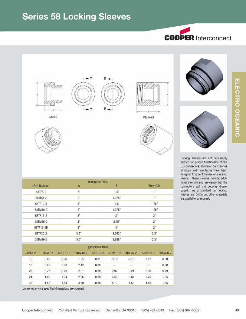
Series 58 Locking Sleeves
Dimension TablePart Number A B Body O.D.
58TF8-2 2” 1.5” 1”
58TM8-2 2’ 1.375” 1”
58TF10-2 2” 1.5 1.25”
58TM10-2 2” 1.375” 1.25”
58TF16-2 3” 3” 2”
58TM16-2 3” 2.75” 2”
58TF16-2B 3” 4” 2”
58TF20-2 3.5” 3.563” 2.5”
58TM20-2 3.5” 3.938” 2.5”
Application Table
58TF8-2 58TM8-2 58TF10-2 58TM10-2 58TF16-2 58TM16-2 58TF16-2B 58TF20-2 58TM20-2
15 0.65 0.68 1.95 0.31 3.19 2.75 2.12 0.68
16 0.65 0.68 2.12 0.38 --- --- --- 0.68
20 0.77 0.79 2.31 0.38 3.97 3.24 2.90 0.79
24 1.02 1.04 2.66 0.38 4.50 3.87 3.25 1.05
32 1.52 1.54 3.50 0.38 5.13 4.50 4.59 1.55
Unless otherwise specified dimensions are nominal.
Locking sleeves are not necessarilyneeded for proper functionality of theE.O. connectors. However, our B seriesof plugs and receptacles have beendesigned to accept the use of a lockingsleeve. These sleeves provide addi-tional strength and assurance that theconnectors will not become disen-gaged. As a standard our lockingsleeves are Delrin but other materialsare available by request.
Cooper Interconnect 750 West Ventura Boulevard Camarillo, CA 93010 (805) 484-0543 Fax: (805) 987-5062 49
ELECTRO OCEANIC
60704_Text_v9_C9599 Cooper_Subsea Cat_p1-19 3/2/12 12:51 PM Page 49

Miniature Connectors Series 56
APPLICATIONSThe Series56 is specifically designedto meet the need for a fluid-immersed, instrumentation-quality,multiconductor electrical connector.As in all Series 50 products, the 56 isbased on the proven, exclusive,WATERMATE™ principle. This permitsplugging underwater, with insulationresistance guaranteed to be greaterthan 100 megohms. Electrical integri-ty of all connectors is preserved to fullocean depths. The Series 56 featuresthe following characteristics:
MINIATUREThe contact size has been reducedwith no loss of current-carryingcapacity
LOW CONTACT RESISTANCE
The female connector employs aclosed entry beryllium copper contactfor low contact resistance and lownoise. Contact resistance is in theorder of 5 milliohm and repeatable.
MODULAR CONSTRUCTION
The series is designed for complexinterconnections and branching, per-mitting an almost limitless number ofinput-output combinations.
The connector comes in 1, 2, 3, 4 & 8circuit modules. 2, 4 & 8 circuit con-nectors are available in “universal”(combination male and female)designs. In the 1, 2, 3, 4 & 8 circuitdesigns there are male and femaleconnectors.
The Series 56 features a conical entrysection to ease blind engagementunderwater. The universal featurecompletely eliminates polarizationproblems.
Unless otherwise specified dimensions are nominal.
ModelNo. of
Circuits
No. of Pins or Sockets
MaxVolts
Face Style
Amps perConnector(Max.)
Wire Size AWG
BIn.
DIn.
LIn.
MatesWith
M F U
56B1 Mor F-1
1 1 1 230 Flat 7.5 18 .25 1.56 1.00 56B1 Mor F-1
56B2 Mor F-2
1 2 2 230 Offset 7.5 18 .50 1.64 1.08 56B2 Mor F-2
56B2 Mor F-1
2 2 2 230 Flat 7.5 18 .50 1.64 1.08 56B2 Mor F-1
56B2 U-1 2 2 1/1 230 Flat 7.5 18 .50 1.64 1.08 56B2 U-1
750 West Ventura Boulevard Camarillo, CA 93010 www.cooperinterconnect.com 50
ELECTRO OCEANIC
60704_Text_v9_C9599 Cooper_Subsea Cat_p1-19 3/2/12 12:51 PM Page 50
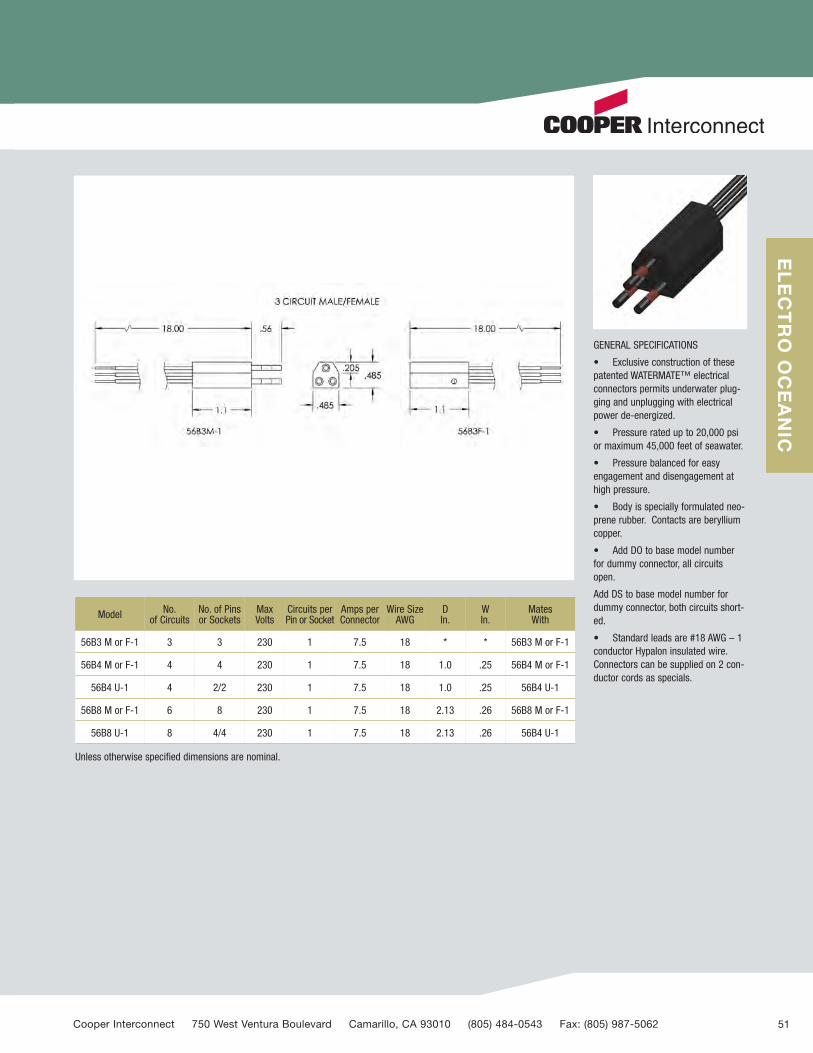
GENERAL SPECIFICATIONS
• Exclusive construction of thesepatented WATERMATE™ electricalconnectors permits underwater plug-ging and unplugging with electricalpower de-energized.
• Pressure rated up to 20,000 psior maximum 45,000 feet of seawater.
• Pressure balanced for easyengagement and disengagement athigh pressure.
• Body is specially formulated neo-prene rubber. Contacts are berylliumcopper.
• Add DO to base model numberfor dummy connector, all circuitsopen.
Add DS to base model number fordummy connector, both circuits short-ed.
• Standard leads are #18 AWG – 1conductor Hypalon insulated wire.Connectors can be supplied on 2 con-ductor cords as specials.
Model No. of Circuits
No. of Pinsor Sockets
MaxVolts
Circuits perPin or Socket
Amps perConnector
Wire SizeAWG
DIn.
WIn.
MatesWith
56B3 M or F-1 3 3 230 1 7.5 18 * * 56B3 M or F-1
56B4 M or F-1 4 4 230 1 7.5 18 1.0 .25 56B4 M or F-1
56B4 U-1 4 2/2 230 1 7.5 18 1.0 .25 56B4 U-1
56B8 M or F-1 6 8 230 1 7.5 18 2.13 .26 56B8 M or F-1
56B8 U-1 8 4/4 230 1 7.5 18 2.13 .26 56B4 U-1
Unless otherwise specified dimensions are nominal.
Cooper Interconnect 750 West Ventura Boulevard Camarillo, CA 93010 (805) 484-0543 Fax: (805) 987-5062 51
ELECTRO OCEANIC
60704_Text_v9_C9599 Cooper_Subsea Cat_p1-19 3/2/12 12:51 PM Page 51

WP Series Waterproof Connectors
DESCRIPTION
The WP and WPS Series are transfermolded from the same specially com-pounded neoprene formula used withunderwater pluggable line of connec-tors. All WP and WPS connectors arevulcanized directly to the cable to pro-vide a positive seal at all pressures upto 20,000 psi.
QUALITY ASSURANCE
WP and WPS connector series aredesigned to meet the highest stan-dards of reliability for this type of con-nector.
TYPICAL APPLICATIONS
Underwater instrumentation and con-trol systems – underwater cameras –underwater lighting systems – under-water habitats – diver communica-tions.
DUMMY PLUGS – Dummy Plugs (Caps)are available for purposes of sealingoff connectors when not in use andalso when possible environmentalexposure could damage the connector.When ordering write “DO” after con-nector designation.
750 West Ventura Boulevard Camarillo, CA 93010 www.cooperinterconnect.com 52
ELECTRO OCEANIC
60704_Text_v9_C9599 Cooper_Subsea Cat_p1-19 3/2/12 12:52 PM Page 52
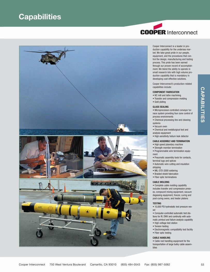
Capabilities
Cooper Interconnect is a leader in pro-duction capability for the undersea mar-ket. We take great pride in our people,equipment, and the procedures that con-trol the design, manufacturing and testingprocess. This pride has been earnedthrough our proven record of accomplish-ment. We blend the ability to operate insmall research lots with high volume pro-duction capability that is mandatory indeveloping cost-effective solutions.
Cooper Interconnect’s production-relatedcapabilities include:
COMPONENT FABRICATION• NC mill and lathe machining• Transfer and compression molding• Gold plating
GLASS SEALING• Microprocessor-controlled conveyor fur-nace system providing four-zone control ofprocess environments• Chemical processing line and cleaningsystems• Vacuum oven• Chemical and metallurgical test andanalysis equipment• High-sensitivity helium leak detector
CABLE ASSEMBLY AND TERMINATION• High speed planetary machine• Strength member termination• Programmable wire termination equip-ment• Pneumatic assembly tools for contacts,terminal lugs and splices• Automatic wire cutting and insulationstripping• MIL-STD-2000 soldering• Braided shield fabrication• Fiber optic terminations
CABLE MOLDING• Complete cable molding capabilityincludes transfer and compression press-es, compound mixing equipment, vacuumdegassing equipment, freezer, curing andpost-curing ovens, and heater platens
TESTING• 10,000 PSI hydrostatic test pressure ves-sel • Computer-controlled automatic test sta-tions for IR, DWV and continuity with auto-matic printout and failure analysis capability• High-voltage test station• Tension testing• Electromagnetic compatibility test facility• Fiber optic testing
CABLE HANDLING• Cable reel handling equipment for thetransportation of large bulky cable assem-blies
CAPABILITIES
Cooper Interconnect 750 West Ventura Boulevard Camarillo, CA 93010 (805) 484-0543 Fax: (805) 987-5062 53
60704_Text_v9_C9599 Cooper_Subsea Cat_p1-19 3/2/12 12:52 PM Page 53

Appendices
Ampacity
The Ampacity or current carrying ability of an insulated conductor is determinedby the maximum temperature the insulation can withstand without significantdegradation for a period of 40 years at standard conditions. The maximum insu-lation temperature is the conductor temperature at the conductor/insulationinterface so the data is usually listed as an allowable Ampacity at a given con-ductor temperature. The Ampacity of a conductor is therefore a problem of heattransfer.
One source of such data is the National Electrical Code (NEC), which list 40 ampsat 90°C for single 12 AWG (3.3 mm)2 copper conductors:
If conductors are bundled together into a cable the heat transfer is reduced andthus the Ampacity of each conductor must also be reduced. The standard ambi-ent temperature for the Ampacity rating above was 30°C for the first 3 and 40°Cfor the last 2. If the ambient temperatures exceed these standard values theAmpacities must also be reduced. There are tables in the NEC for this purpose.
But an underwater vehicle is not a building nor is it expected to last for 40 years.This means that liberties may be taken with the very conservative NEC ratings atno great peril. The insulation degradation process is essentially a chemicalprocess so if the conductor temperature is increased 10°C the life of the insulat-ed conductor is halved. There is, of course, an upper limit to the maximum con-ductor temperature when the insulation degradation becomes nonlinear. ToCooper Interconnect’s knowledge no studies have been made on this aspectconductor temperature when of Ampacity. Cooper Interconnect uses type SOcable in most of its products and this cable is rated @ 90°C.
There are many other considerations, of course. Water is an excellent heat sinkso in-water operation is not usually a problem. Cooper Interconnect hasreceived reports of successful operations in excess of 4x recommended ampaci-ty in fully submerged applications. However, be cautioned that checkout andtesting on deck can be a problem if the benefit of in-water operation is factoredinto the ampacity although heat buildup is relatively slow most of the time andshort “overload” periods are usually tolerated. Caution must be exercised if awire overheats the insulation may be damaged enough to preclude its operationas a voltage insulator.
Because Ampacity is such a complex subject most designers are as cautious asCooper Interconnect in specifying the Ampacity of the wire and cable in theirequipment.
Cooper Interconnect does not guarantee the accuracy of the NEC data. It is up tothe customer to determine the correct conductor size and ampacity for his appli-cation.
This table summarizes the NEC data:
750 West Ventura Boulevard Camarillo, CA 93010 www.cooperinterconnect.com 54
60704_Text_v9_C9599 Cooper_Subsea Cat_p1-19 3/2/12 12:52 PM Page 54
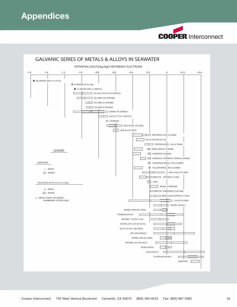
Appendices
Cooper Interconnect 750 West Ventura Boulevard Camarillo, CA 93010 (805) 484-0543 Fax: (805) 987-5062 55
60704_Text_v9_C9599 Cooper_Subsea Cat_p1-19 3/2/12 12:52 PM Page 55

Appendices
Engagement and Disengagement of ConnectorAlways be sure the power is turned off before eitherengaging or disengaging a connector. Electrical shocks are easy to get (especially ona wet deck) but hard on people and equipment.
To Engage:1. Lightly coat the face, sides and sealing surface of the plug with clean Dow CorningDC-4 silicone grease. Be sure there is no moisture on the components.2. Align the polarizing keyway in plug and receptacle and push to engage the con-tacts. Push the plug in until the rubber sealing surface and the metal sealing surfacetouch. A gentle rocking motion will allow trapped air to escape. On the 32 size con-nectors with many contacts it takes quite a bit of push. Using the coupling nut as anaid to engagement is acceptable but never use a wrench.3. When the sealing surfaces touch, spin the coupling nut on until it just touches andgive it an additional one half turn (1 full turn on 15 size). Caution: The sealing sur-faces must be touching for the additional half turn to seal the connector properly. Ifthe coupling nut is used as an aid to engagement, back the nut off completely toobtain visual confirmation of the sealing surface contact. Then spin the nut back onand add the turn. Applying more turns than specified will distort the rubber, possiblyresulting in leakage and/or physical damage.
To Disengage:1. Unscrew the coupling nut completely. Note: After deep initial dives the nut may beloose. This is normal. 2. Grasp the connector body firmly and pull the plug out. Gentle rocking motion mayease pull. Caution: Do not disengage the plug by pulling on the cable; it may break awire inside the connector.
Receptacle Installation:The O-Ring sealing surfaces of the receptacles and pressure vessels require an RMS32 finish, free of scratches, dents, or nicks. Apply a thin coat of clean Dow CorningDC-4 silicone grease to the O-Ring and install the O-Ring in its groove. Remove O-Ring with a nonmetallic object only (such as a wooden tooth pick). For bulkheadreceptacles, apply a light coat of oil or antiseize compound to the mounting threads(be careful not to get any on the O-Ring) and assemble the unit. The bulkhead con-nectors should be torqued to the following specifications:
For panel mount receptacles, use 4 bolts to hold them in place. The recommendedbolt sizes and torques are:
The above torques are minimum values which will be acceptable. They may beincreased base upon the engineer's knowledge of bolt diameter, thread pitch and thematerial used for both the bolts and the housing.
Cleaning and Re-useA. Clean the plug and receptacle carefully by hand. Use only a bristle brush (no metalallowed) liquid soap and water.B. Dry the connection by shaking off excess water then using alcohol to eliminate theremaining water as described below.C. Flood the connector with alcohol, then pour it out and allow the connector to air-dry. Caution: Compressed air contains many contaminants such as water, oil anddust and must not be used. Use alcohol only in a well-ventilated area.
Inspection:A. Inspect the connector for bent or otherwise damaged pins and corrosion.B. Metal sealing surfaces must have a RMS 32 finish and be free of scratches, nicksand dents. This applies to both O-Ring sealing surfaces and connector sealing sur-faces.C. The rubber sealing surfaces must be free of cuts, nicks and tears. Notes: On usedconnectors, the rubber sealing surface may have and impression of the metal seal-ing surface on it. This is normal.D. The cable and rubber-molded plug must be free of cuts, tears and separations.Carefully inspect the rubber condition near the metal shell. Tears are common here,caused by using the connector in a bent position or using it as a handle.E. When the connectors are being re-used, remember to always use new O-Rings inthe receptacles and to inspect the threads of the coupling nut for the presence of dry-film lubrication use to prevent galling of the metal. A light coat of “Molylube” may beused if necessary.F. In several instances, Cooper Interconnect recommends using a thin (or Light) coatof silicone grease. It is of the utmost importance to use silicone grease sparingly. Insmall quantities it is your O-Ring and your connectors’ best friend. In large quantitiesit is your O-Ring and your connectors’ worst enemy. Light films reduce friction andallow the components to work as they are designed. Larger quantities create theequivalent of a “Hydraulic Lock” and completely destroy the function of the O-Ringand/or connector.
Shell Bolt Torque15 #10 25 lb-In
16 #10 25 lb-In
20 1/4 45 lb-In
24 1/4 45 lb-In
32 5/16 85 lb-In
Shell Torque15 125 lb-In
16 125 lb-In
20 165 lb-In
24 225 lb-In
32 335 lb-In
750 West Ventura Boulevard Camarillo, CA 93010 www.cooperinterconnect.com 56
60704_Text_v9_C9599 Cooper_Subsea Cat_p1-19 3/2/12 12:52 PM Page 56

Notes
Cooper Interconnect 750 West Ventura Boulevard Camarillo, CA 93010 (805) 484-0543 Fax: (805) 987-5062
60704_Cover.qxd:Layout 1 3/1/12 3:37 PM Page 3

Reorder # CI-Subsea102010 Printed in USA
Cooper Interconnect’s Subsea Connectors are manufactured at750 West Ventura BoulevardCamarillo, CA 93010P: 805-484-0543F: 805-987-5062
Cooper Interconnect
222 Williams StreetChelsea, MA 02150P: 617-889-3700F: 617-889-6980
Cooper Interconnect
23 Front StreetSalem, NJ 08079P: 856-935-7560F: 856-935-0102
www.cooperinterconnect.comemail [email protected]
Cooper Interconnect is a trademark of Cooper Industries, Inc.©2012 Cooper Industries, Inc.
Cooper Industries, Ltd.600 Travis, Ste. 5800Houston, TX 77002-1001P: 713-209-8400www.cooperindustries.com
4758 Washington StreetLaGrange, NC 28551P: 252-566-3014F: 252-566-9337
60704_Cover.qxd:Layout 1 3/1/12 3:37 PM Page 4