Embed Size (px)
Citation preview
part of Aker
© 2008 Aker Solutions
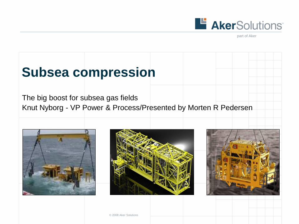
Subsea compression
The big boost for subsea gas fields
Knut Nyborg - VP Power & Process/Presented by Morten R Pedersen
© 2008 Aker Solutions part of Aker to edit this text Slide 2
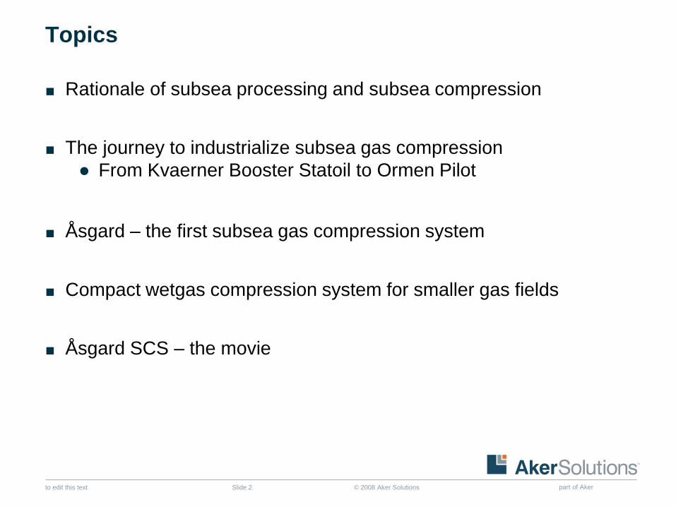
Topics
■ Rationale of subsea processing and subsea compression
■ The journey to industrialize subsea gas compression
● From Kvaerner Booster Statoil to Ormen Pilot
■ Åsgard – the first subsea gas compression system
■ Compact wetgas compression system for smaller gas fields
■ Åsgard SCS – the movie
© 2008 Aker Solutions part of Aker to edit this text Slide 3
Summary
■ Aker Solutions and its clients have industrialised subsea compression for long step-out, deep water (3000 ft) and large volumes (25 – 60 MW)
■ The Ormen Pilot is the single largest development and qualification programme in the subsea industry and is now nearing its completion
■ The Åsgard SCS will be the worlds first subsea compression system when it is installed in 2014
■ The business case for subsea compression looks promising for most large subsea gas fields
■ Aker Solutions is now focusing on the development of a more compact and smaller subsea compression system for medium and small gas fields
© 2008 Aker Solutions part of Aker to edit this text Slide 4
Topics
■ Rationale of subsea processing and subsea compression
■ The journey to industrialize subsea gas compression
● From Kvaerner Booster Statoil to Ormen Pilot
■ Åsgard – the first subsea gas compression system
■ Compact wetgas compression system for smaller gas fields
■ Åsgard SCS – the movie
© 2008 Aker Solutions part of Aker to edit this text Slide 5
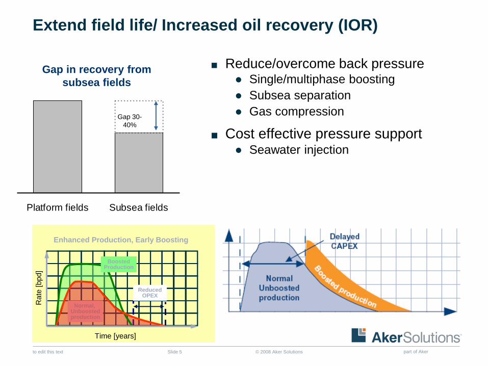
Extend field life/ Increased oil recovery (IOR)
■ Reduce/overcome back pressure ● Single/multiphase boosting
● Subsea separation
● Gas compression
■ Cost effective pressure support ● Seawater injection
Gap in recovery from
subsea fields
Platform fields Subsea fields
Gap 30-
40%
Normal, Unboostedproduction
Enhanced Production, Early Boosting
ReducedOPEX
BoostedProduction
Rate
[bpd
]
Time [years]
Normal, Unboostedproduction
Enhanced Production, Early Boosting
ReducedOPEX
BoostedProduction
Rate
[bpd
]
Time [years]
© 2008 Aker Solutions part of Aker to edit this text Slide 7
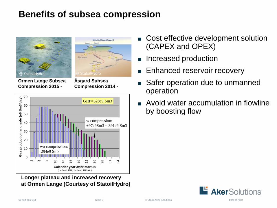
Benefits of subsea compression
■ Cost effective development solution (CAPEX and OPEX)
■ Increased production
■ Enhanced reservoir recovery
■ Safer operation due to unmanned operation
■ Avoid water accumulation in flowline by boosting flow
Longer plateau and increased recovery
at Ormen Lange (Courtesy of StatoilHydro)
Ormen Lange Subsea
Compression 2015 -
Åsgard Subsea
Compression 2014 -
@ StatoilHydro @ StatoilHydro
0
10
20
30
40
50
60
70
1 4 7
10
13
16
19
22
25
28
31
34
Calender year after startup(1 = Jan 1 2008, 2 = Jan 1 2009 etc)
Ga
s p
rod
uc
tio
n a
nd
sa
le (
e6
Sm
3/d
ay
)
wo compression:
294e9 Sm3
GIIP=528e9 Sm3
w compression:
+97e9Sm3 = 391e9 Sm3
0
10
20
30
40
50
60
70
1 4 7
10
13
16
19
22
25
28
31
34
Calender year after startup(1 = Jan 1 2008, 2 = Jan 1 2009 etc)
Ga
s p
rod
uc
tio
n a
nd
sa
le (
e6
Sm
3/d
ay
)
wo compression:
294e9 Sm3
GIIP=528e9 Sm3
w compression:
+97e9Sm3 = 391e9 Sm3
© 2008 Aker Solutions part of Aker to edit this text Slide 9
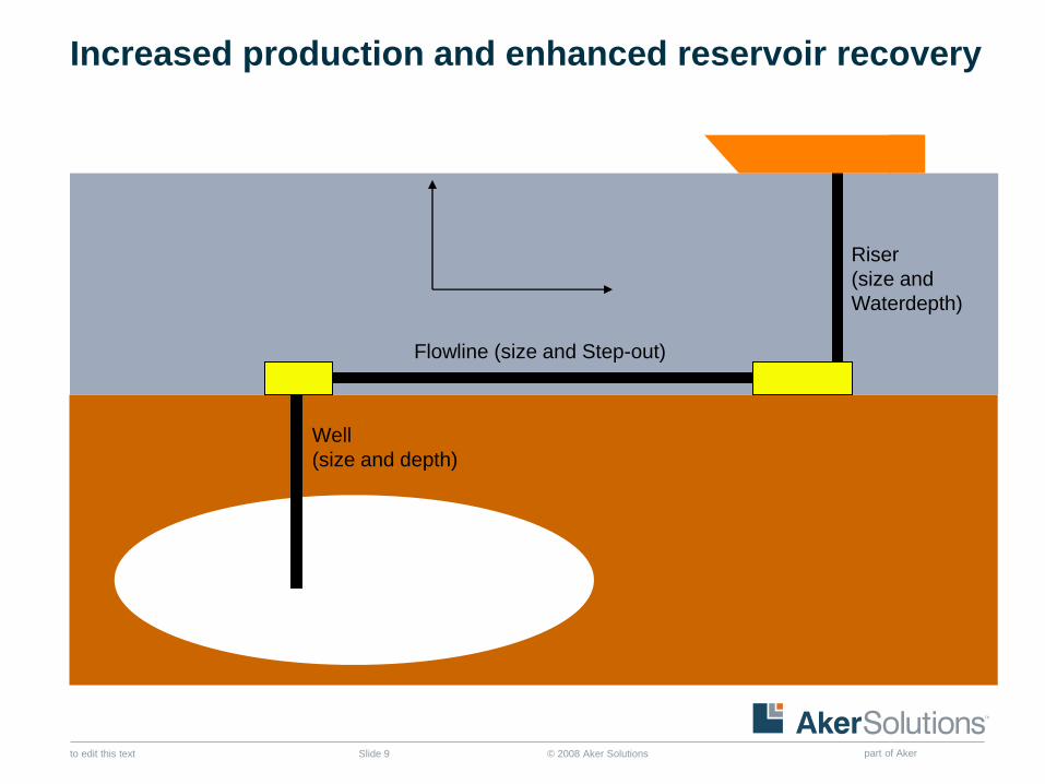
Increased production and enhanced reservoir recovery
Well
(size and depth)
Riser
(size and
Waterdepth)
Flowline (size and Step-out)
© 2008 Aker Solutions part of Aker to edit this text Slide 10
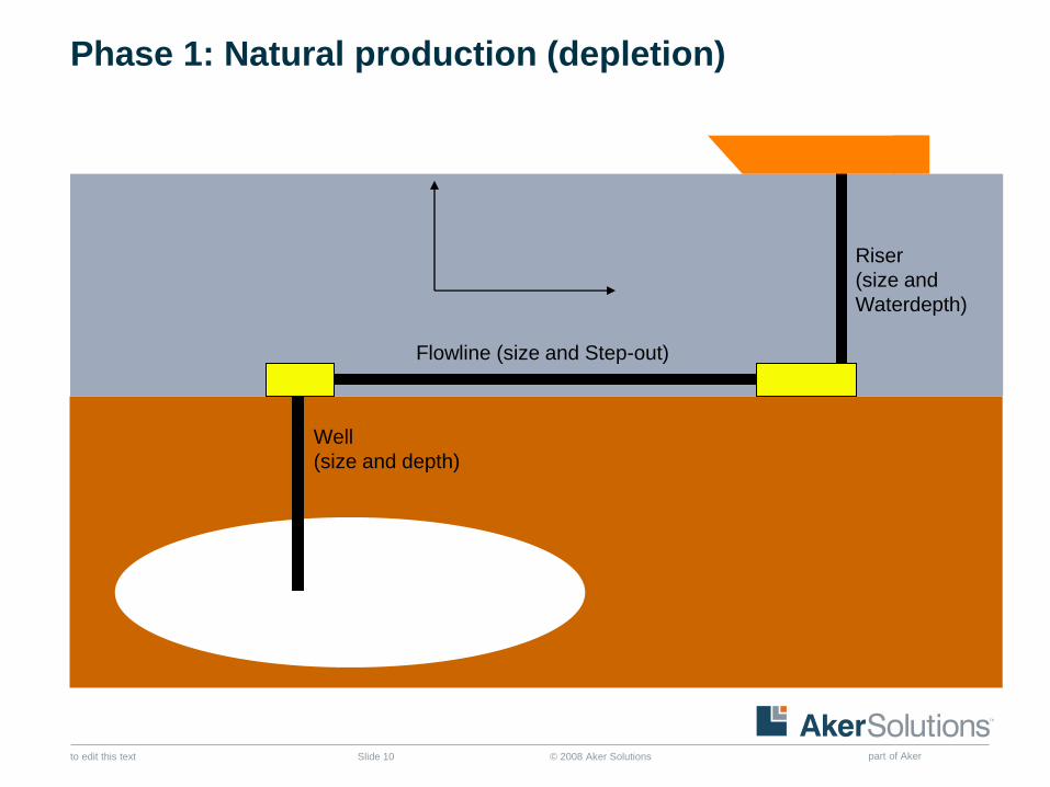
Phase 1: Natural production (depletion)
Well
(size and depth)
Riser
(size and
Waterdepth)
Flowline (size and Step-out)
© 2008 Aker Solutions part of Aker to edit this text Slide 11
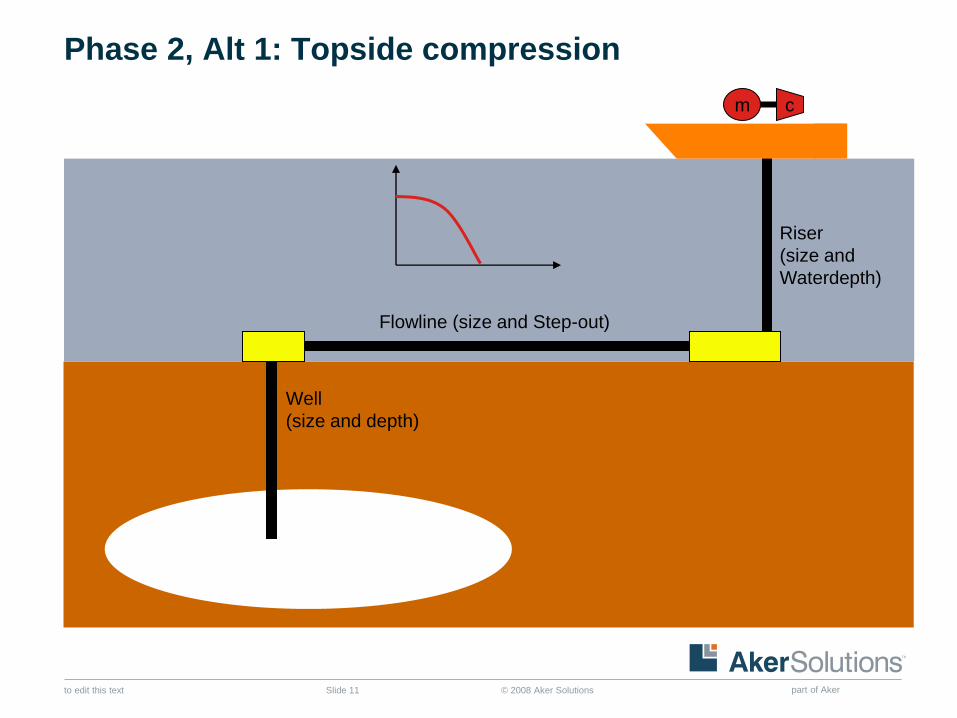
Phase 2, Alt 1: Topside compression
Well
(size and depth)
Riser
(size and
Waterdepth)
Flowline (size and Step-out)
c m
© 2008 Aker Solutions part of Aker to edit this text Slide 12
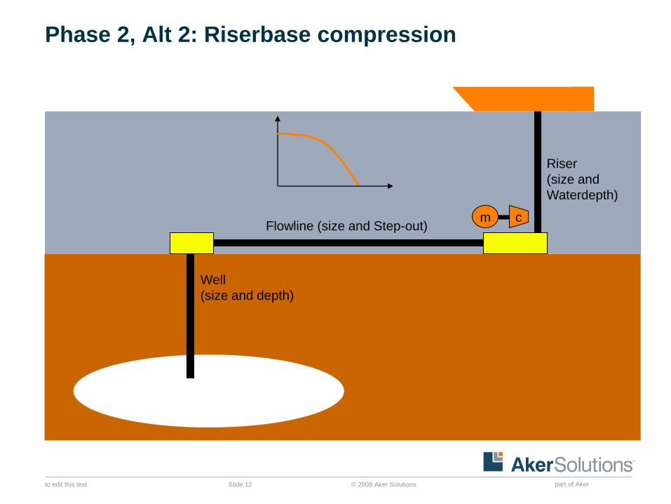
Phase 2, Alt 2: Riserbase compression
Well
(size and depth)
Riser
(size and
Waterdepth)
Flowline (size and Step-out) c m
© 2008 Aker Solutions part of Aker to edit this text Slide 13
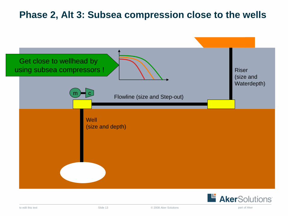
Phase 2, Alt 3: Subsea compression close to the wells
Well
(size and depth)
Riser
(size and
Waterdepth)
Flowline (size and Step-out) c m
Get close to wellhead by
using subsea compressors !
© 2008 Aker Solutions part of Aker to edit this text Slide 14
Topics
■ Rationale of subsea processing and subsea compression
■ The journey to industrialize subsea gas compression
● From Kvaerner Booster Statoil to Ormen Pilot
■ Åsgard – the first subsea gas compression system
■ Compact wetgas compression system for smaller gas fields
■ Åsgard SCS – the movie
© 2008 Aker Solutions part of Aker to edit this text Slide 15
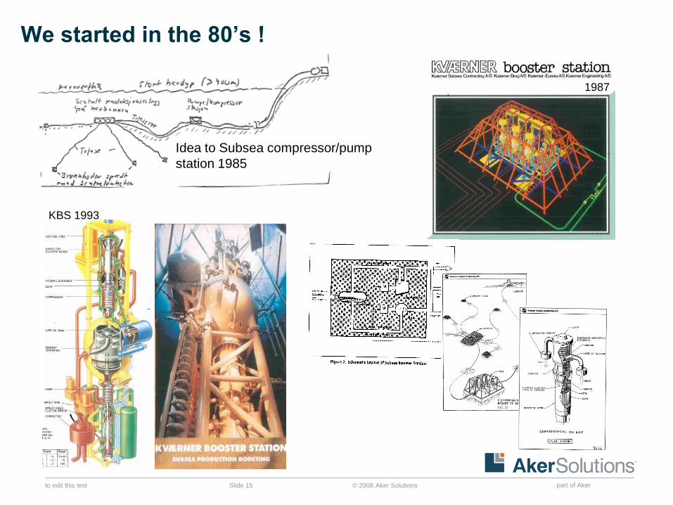
1987
Idea to Subsea compressor/pump
station 1985
KBS 1993
We started in the 80’s !
© 2008 Aker Solutions part of Aker to edit this text Slide 16
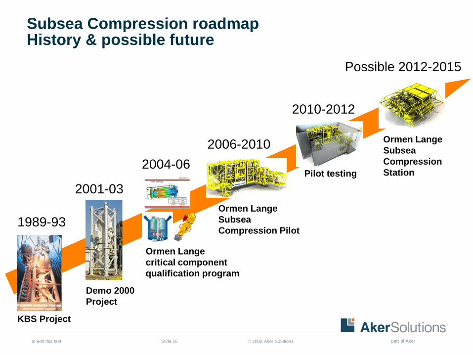
Possible 2012-2015
Subsea Compression roadmap History & possible future
2001-03
Demo 2000
Project
Ormen Lange
Subsea
Compression
Station
Ormen Lange
Subsea
Compression Pilot
2006-2010
Ormen Lange
critical component
qualification program
2004-06
KBS Project
1989-93
Pilot testing
2010-2012
© 2008 Aker Solutions part of Aker to edit this text Slide 17
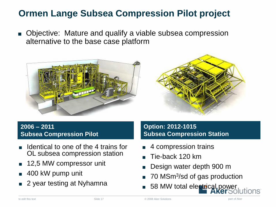
Ormen Lange Subsea Compression Pilot project
Option: 2012-1015
Subsea Compression Station
■ 4 compression trains
■ Tie-back 120 km
■ Design water depth 900 m
■ 70 MSm3/sd of gas production
■ 58 MW total electrical power
2006 – 2011
Subsea Compression Pilot
■ Identical to one of the 4 trains for OL subsea compression station
■ 12,5 MW compressor unit
■ 400 kW pump unit
■ 2 year testing at Nyhamna
■ Objective: Mature and qualify a viable subsea compression alternative to the base case platform
© 2008 Aker Solutions part of Aker to edit this text Slide 18
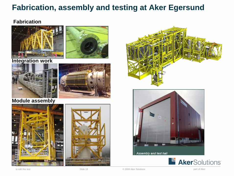
Fabrication, assembly and testing at Aker Egersund
Integration work
Module assembly
Fabrication
© 2008 Aker Solutions part of Aker to edit this text Slide 19
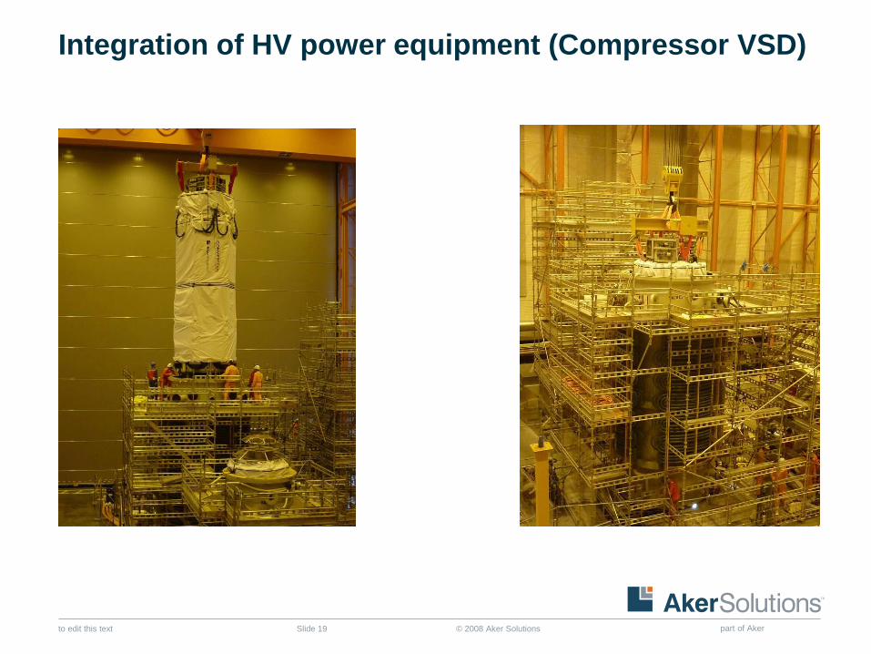
Integration of HV power equipment (Compressor VSD)
© 2008 Aker Solutions part of Aker to edit this text Slide 20
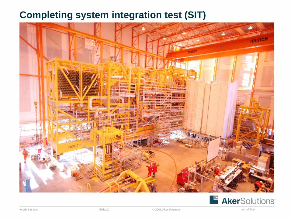
Completing system integration test (SIT)
© 2008 Aker Solutions part of Aker to edit this text Slide 21
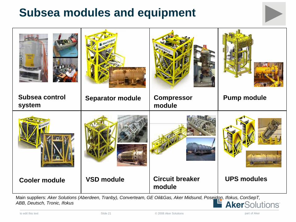
Subsea modules and equipment
Separator module
Compressor
module
VSD module
Pump module
UPS modules Circuit breaker
module
Cooler module
Subsea control
system
Main suppliers: Aker Solutions (Aberdeen, Tranby), Converteam, GE Oil&Gas, Aker Midsund, Poseidon, Ifokus, ConSepT,
ABB, Deutsch, Tronic, Ifokus
© 2008 Aker Solutions part of Aker to edit this text Slide 22
Topics
■ Rationale of subsea processing and subsea compression
■ The journey to industrialize subsea gas compression
● From Kvaerner Booster Statoil to Ormen Pilot
■ Åsgard – the first subsea gas compression system
■ Compact wetgas compression system for smaller gas fields
■ Åsgard SCS – the movie
© 2008 Aker Solutions part of Aker to edit this text Slide 23
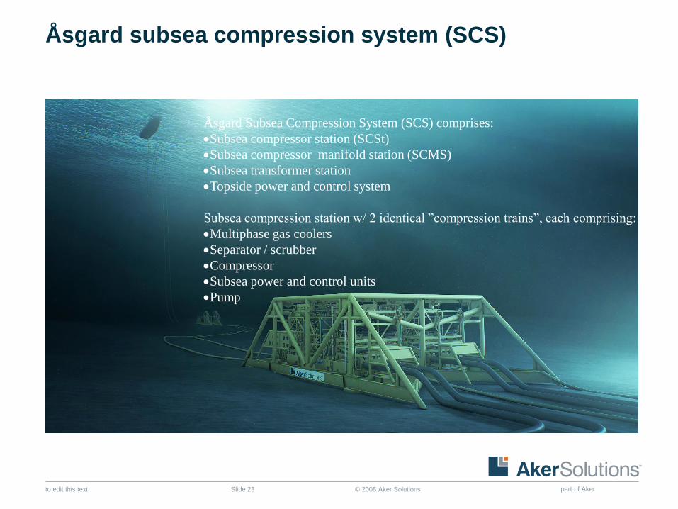
Åsgard subsea compression system (SCS)
Åsgard Subsea Compression System (SCS) comprises:
Subsea compressor station (SCSt)
Subsea compressor manifold station (SCMS)
Subsea transformer station
Topside power and control system
Subsea compression station w/ 2 identical ”compression trains”, each comprising:
Multiphase gas coolers
Separator / scrubber
Compressor
Subsea power and control units
Pump
© 2008 Aker Solutions part of Aker to edit this text Slide 24
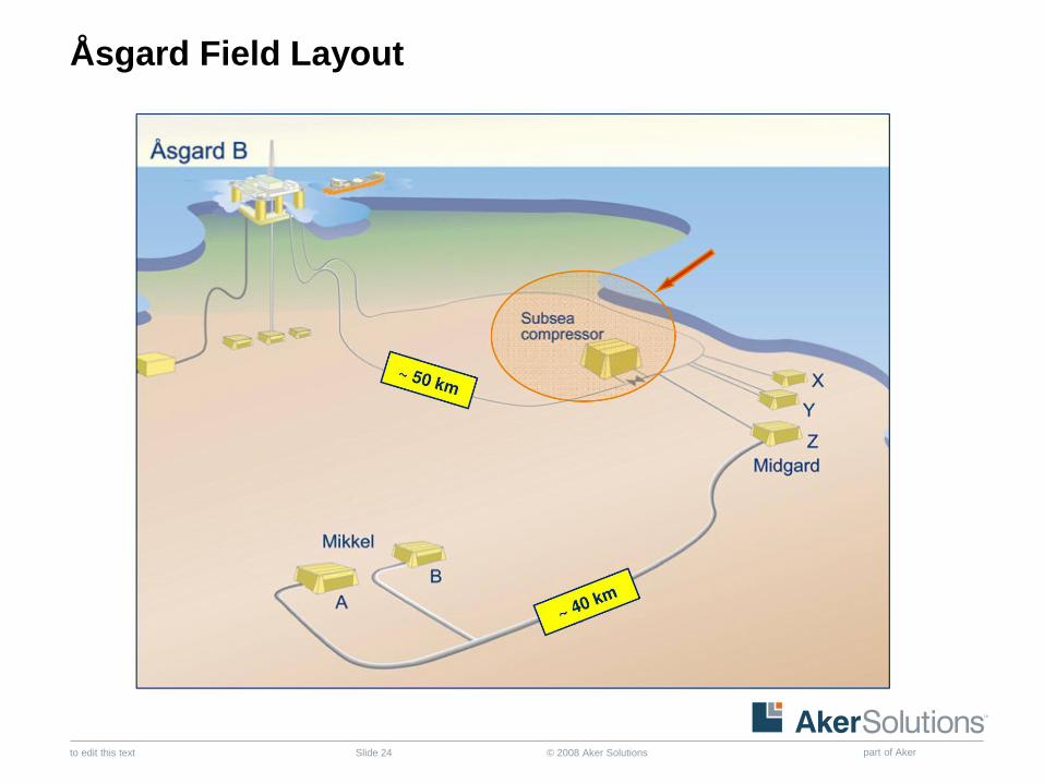
Åsgard Field Layout
© 2008 Aker Solutions part of Aker to edit this text Slide 25
25
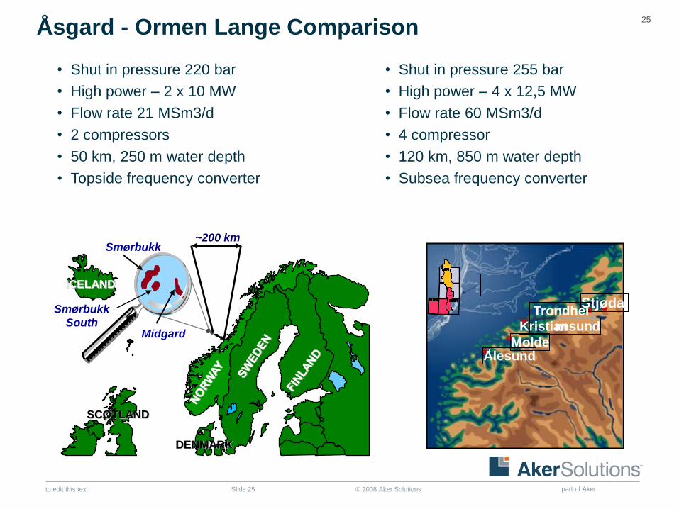
Åsgard - Ormen Lange Comparison
Stjødal Trondhei
m Kristiansund
Molde Ålesund
PL208
ICELAND
DENMARK
SCOTLAND
~200 km
Midgard
Smørbukk
Smørbukk
South
• Shut in pressure 220 bar
• High power – 2 x 10 MW
• Flow rate 21 MSm3/d
• 2 compressors
• 50 km, 250 m water depth
• Topside frequency converter
• Shut in pressure 255 bar
• High power – 4 x 12,5 MW
• Flow rate 60 MSm3/d
• 4 compressor
• 120 km, 850 m water depth
• Subsea frequency converter
© 2008 Aker Solutions part of Aker to edit this text Slide 26
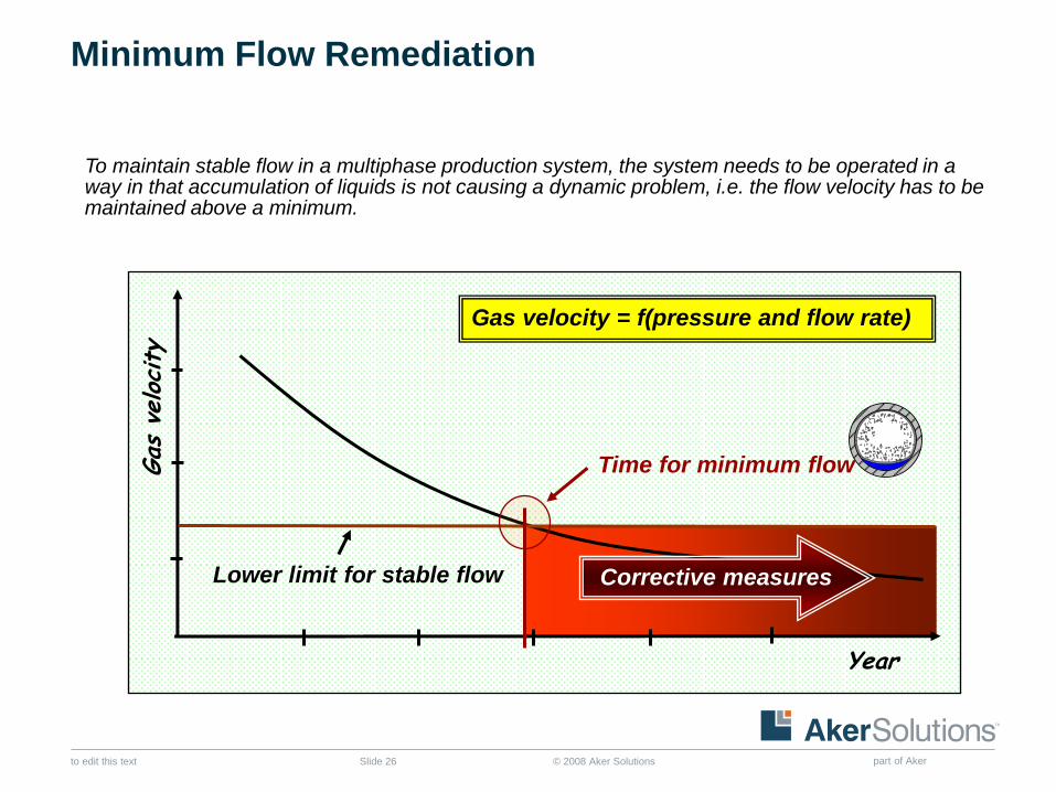
Gas
veloc
ity
Time for minimum flow
Year
Lower limit for stable flow
Gas velocity = f(pressure and flow rate)
Corrective measures
To maintain stable flow in a multiphase production system, the system needs to be operated in a way in that accumulation of liquids is not causing a dynamic problem, i.e. the flow velocity has to be maintained above a minimum.
Minimum Flow Remediation
© 2008 Aker Solutions part of Aker to edit this text Slide 27
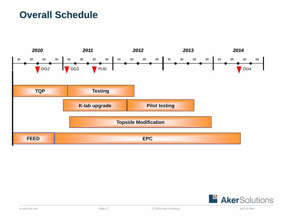
Overall Schedule
FEED
K-lab upgrade
TQP
EPC
Pilot testing
2010
Q1 Q2 Q3 Q4 Q1 Q2 Q3 Q4 Q1 Q2 Q3 Q4 Q1 Q2 Q3 Q4 Q1 Q2 Q3 Q4
2011 2012 2013 2014
DG2 DG3 DG4
Topside Modification
PUD
Testing
© 2008 Aker Solutions part of Aker to edit this text Slide 28
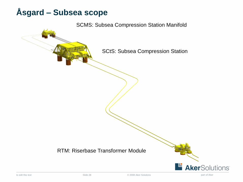
Åsgard – Subsea scope
SCMS: Subsea Compression Station Manifold
SCtS: Subsea Compression Station
RTM: Riserbase Transformer Module
© 2008 Aker Solutions part of Aker to edit this text Slide 29
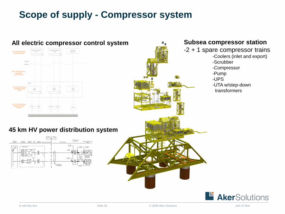
Scope of supply - Compressor system
11 kV50 Hz
Topside VSDs
Subsea Compressors and
pumps
Topsides Subsea
Step-down
transformerFrequency
Converter
Sine
filter
Step-up
transformer
Platform
Switchboard Power umbilical
Combined in
one umbilical
Subsea Step-down
transformer
M P
12MW/6.6kV
Compressor
500kW/2.8kV
Liquid pump
HV cable
termination
Transformer
penetrator Transformer
penetrator
Compressor
penetrator
HV cable
termination
CM
If required
If required
cable spliceEarth switch
Wet mate
connectors
& Jumpers
Pump motor
penetrator
PZT01
A
PZT01
B
PT01
A
PT01
B
PCS
SEMA
B
A
B
A
B
A
B
Topside Controller
PCS
Topside Controller
PSD
PSD
SEM
PCS / PSD CM system
segregated subsea
(sensors)
PCS /PSD/CM system
segregated topside
PCS /PSD/CM system
segregated subsea
(SEM)
PCS / PSD/CM system
segregated
(communication)
PT02
Topside
CM server
CM
SEM
SCM
Topside
Subsea
45 km HV power distribution system
All electric compressor control system Subsea compressor station
-2 + 1 spare compressor trains -Coolers (inlet and export)
-Scrubber
-Compressor
-Pump
-UPS
-UTA w/step-down
transformers
© 2008 Aker Solutions part of Aker to edit this text Slide 30
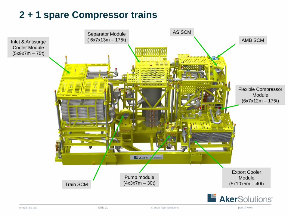
2 + 1 spare Compressor trains
Inlet & Antisurge
Cooler Module
(5x9x7m – 75t)
Separator Module
( 6x7x13m – 175t)
Flexible Compressor
Module
(6x7x12m – 175t)
Pump module
(4x3x7m – 30t)
Export Cooler
Module
(5x10x5m – 40t) Train SCM
AMB SCM
AS SCM
© 2008 Aker Solutions part of Aker to edit this text Slide 31
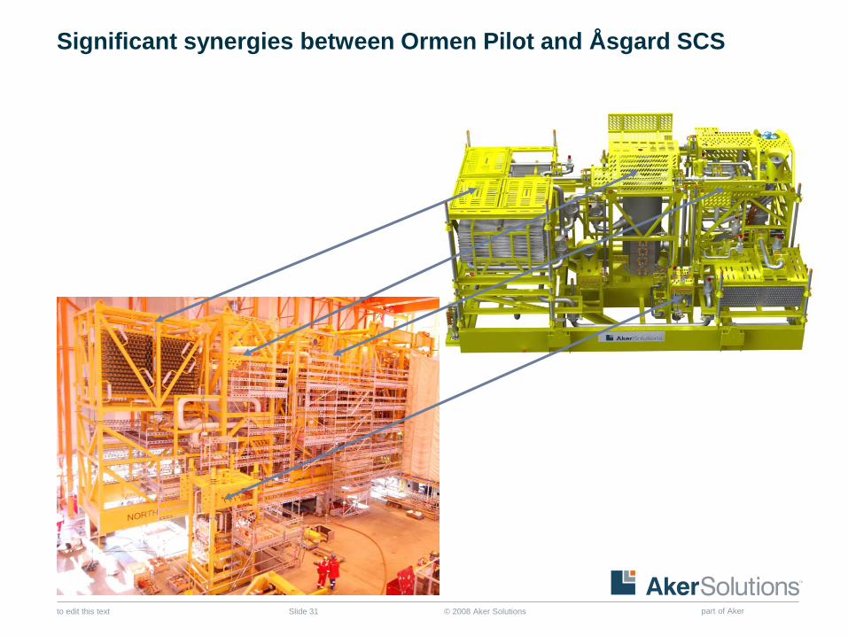
Significant synergies between Ormen Pilot and Åsgard SCS
© 2008 Aker Solutions part of Aker to edit this text Slide 32
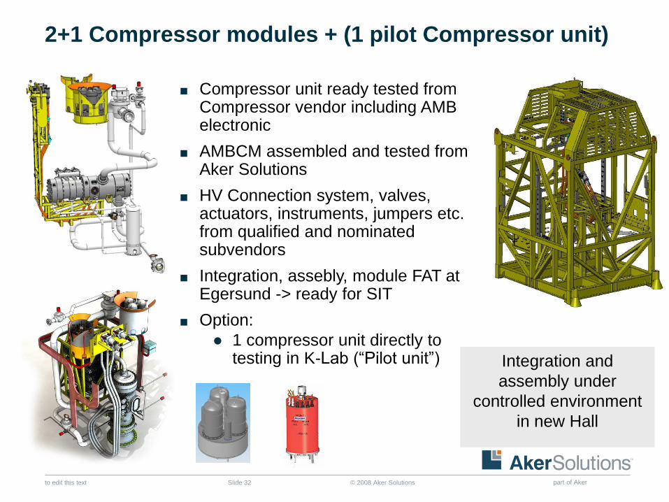
2+1 Compressor modules + (1 pilot Compressor unit)
■ Compressor unit ready tested from Compressor vendor including AMB electronic
■ AMBCM assembled and tested from Aker Solutions
■ HV Connection system, valves, actuators, instruments, jumpers etc. from qualified and nominated subvendors
■ Integration, assebly, module FAT at Egersund -> ready for SIT
■ Option:
● 1 compressor unit directly to testing in K-Lab (“Pilot unit”) Integration and
assembly under
controlled environment
in new Hall
© 2008 Aker Solutions part of Aker to edit this text Slide 33
Topics
■ Rationale of subsea processing and subsea compression
■ The journey to industrialize subsea gas compression
● From Kvaerner Booster Statoil to Ormen Pilot
■ Åsgard – the first subsea gas compression system
■ Compact wetgas compression system for smaller gas fields
■ Åsgard SCS – the movie
© 2008 Aker Solutions part of Aker to edit this text Slide 34
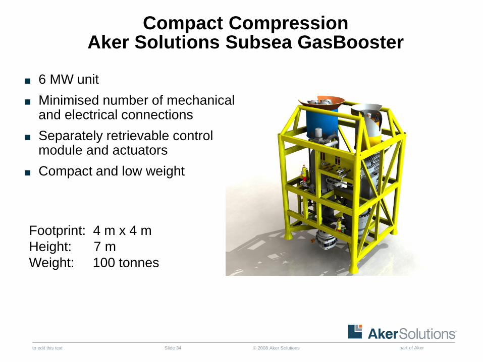
Compact Compression Aker Solutions Subsea GasBooster
■ 6 MW unit
■ Minimised number of mechanical and electrical connections
■ Separately retrievable control module and actuators
■ Compact and low weight
Footprint: 4 m x 4 m
Height: 7 m
Weight: 100 tonnes
© 2008 Aker Solutions part of Aker to edit this text Slide 35
Topics
■ Rationale of subsea processing and subsea compression
■ The journey to industrialize subsea gas compression
● From Kvaerner Booster Statoil to Ormen Pilot
■ Åsgard – the first subsea gas compression system
■ Compact wetgas compression system for smaller gas fields
■ Åsgard SCS – the movie

© 2008 Aker Solutions part of Aker to edit this text Slide 36
Copyright
Copyright of all published material including photographs, drawings and images in this document remains vested in Aker Solutions and third party contributors as appropriate. Accordingly, neither the whole nor any part of this document shall be reproduced in any form nor used in any manner without express prior permission and applicable acknowledgements. No trademark, copyright or other notice shall be altered or removed from any reproduction.
© 2008 Aker Solutions part of Aker to edit this text Slide 37
Disclaimer
This Presentation includes and is based, inter alia, on forward-looking information and statements that are subject to risks and uncertainties that could cause actual results to differ. These statements and this Presentation are based on current expectations, estimates and projections about global economic conditions, the economic conditions of the regions and industries that are major markets for Aker Solutions ASA and Aker Solutions ASA’s (including subsidiaries and affiliates) lines of business. These expectations, estimates and projections are generally identifiable by statements containing words such as “expects”, “believes”, “estimates” or similar expressions. Important factors that could cause actual results to differ materially from those expectations include, among others, economic and market conditions in the geographic areas and industries that are or will be major markets for Aker Solutions’ businesses, oil prices, market acceptance of new products and services, changes in governmental regulations, interest rates, fluctuations in currency exchange rates and such other factors as may be discussed from time to time in the Presentation. Although Aker Solutions ASA believes that its expectations and the Presentation are based upon reasonable assumptions, it can give no assurance that those expectations will be achieved or that the actual results will be as set out in the Presentation. Aker Solutions ASA is making no representation or warranty, expressed or implied, as to the accuracy, reliability or completeness of the Presentation, and neither Aker Solutions ASA nor any of its directors, officers or employees will have any liability to you or any other persons resulting from your use.
Aker Solutions consists of many legally independent entities, constituting their own separate identities. Aker Solutions is used as the common brand or trade mark for most of these entities. In this presentation we may sometimes use “Aker Solutions”, “we” or “us” when we refer to Aker Solutions companies in general or where no useful purpose is served by identifying any particular Aker Solutions company.


![[PPT]Teledyne-ODI Template - HOME « Institute of Nuclear …vlvnt09/parallel_slides/mudge... · Web viewHermetic Penetrator – Need photo of the hermetic penetrator Customer and](https://img.pdfslide.us/doc/110x75/5aaf6d997f8b9a07498d5134/pptteledyne-odi-template-home-institute-of-nuclear-vlvnt09parallelslidesmudgeweb.jpg)


![Cloud penetrator-hakin9-review -march-2012]](https://img.pdfslide.us/doc/110x75/55549a0ab4c905fd608b45d1/cloud-penetrator-hakin9-review-march-2012.jpg)