Embed Size (px)
Citation preview

T-6B JPPT 1542.166A
Simulator Event Briefing Guide
JPPT 1542.166A C3203
Sim
ula
tor
Event In
stru
cto
r Guid
e
PR
IMA
RY
AN
D IN
TE
RM
ED
IAT
E M
ULT
I-SE
RV
ICE
NF
O/W
SO
TR
AIN
ING
SY
ST
EM
Gra
din
g G
uid
elin
es –
I20
01
C3203 Briefing Guide
(Worksheet)
Planned Route:
Takeoff: KNSE, Runway as req. Altitude: MOA Limits Route: KNSE, North MOA, Brewton, Evergreen Training Device: OFT
SYLLABUS NOTES: Introduce and practice the following during this block of training:
Landing pattern procedures, Local departures and course rules, Local radio procedures Engine failures and malfunctions, PEL, Forced Landings and ELP’s.
No strap-in required for student. Need to have gloves, kneeboard, NATOPS PCL for this event.
Student will use Abbreviated Simulator checklist to expedite becoming airborne. Once airborne all applicable checklist will be conducted from the quad-fold version.
Special Syllabus Requirement Aborted Takeoff and Aircraft Departs Prepared Surface
Discuss
a. Crosswind takeoff / touch-and-go / full-stop landings Crosswind Limits (NATOPS / FTI) Calculate Crosswind Component Precautions for takeoff Overshooting Undershooting Precautions for landing / (Crosswind Landing Video)
b. Aborted takeoff Reasons to conduct an aborted takeoff Critical Action Items How to obtain Maximum Braking Action
c. Aircraft departs prepared surface Procedural Steps Activation of CFS or Ejection considerations
NATOPS QUAD FOLD Wind Chart
Ejection Seat Sequence Mitigation Procedures
Maximum abort speed - definition
Calculate Max Abort Speed (wet runway)

T-6B CONTACT C3200 BLOCK
STUDENT GRADE SHEET DATE __________________ INSTRUCTOR __________________________ MEDIA: OFT VT- ________ BRIEF TIME: ________ NAME: ___________________________ EVENT:_______________
# MANEUVER MIF C3201 C3202 C3203 1 GEN KNOWLEDGE / PROCEDURES 3+ X X X 2 EMERGENCY PROCEDURES 3+ X X X 3 HEADWORK / SITUATIONAL AWARENESS 2+ X X X 4 BASIC AIRWORK 3+ X X X 5 IN-FLIGHT CHECKS / FUEL MANAGEMENT 3+ X X X 6 IN-FLIGHT PLANNING /
AREA ORIENTATION 2+ X X X
7 TASK MANAGEMENT 3+ X X X 8 COMMUNICATION 2+ X X X 9 MISSION PLANNING/BRIEFING/DEBRIEFING 2+ X X X 10 GROUND OPERATIONS 3+ X X X 11 TAKEOFF 3+ X X X 12 DEPARTURE 3+ X X X 13 G-AWARENESS / EXERCISE 2 14 TURN PATTERN 3 15 LEVEL SPEED CHANGE 3 16 SLOW FLIGHT 3 17 POWER-ON STALLS 2 18 LANDING PATTERN STALLS 2 19 EMERGENCY LANDING PATTERN STALLS 2 20 SPIN 2+ X 21 CONTACT UNUSUAL ATTITUDES 2+ X 30 SLIP 2+ X 31 POWER LOSS 2+ X X 32 PRECAUTIONARY EMERGENCY LANDING 2+ X X X 33 PEL/P 2+ X X X 34 ELP LANDING 2+ X X X 35 ARRIVAL / COURSE RULES 2+ X X 36 LANDING PATTERN 2+ X X X 37 NO FLAP LANDING 2 37 TAKEOFF FLAP LANDING 2 37 LDG FLAP LANDING 2 37 FULL STOP LANDING 2+ X 39 WAVEOFF 2+ X X SPECIAL SYLLABUS REQUIREMENT 1 X
SSR: C3203 ABORTED TAKEOFF AND AIRCRAFT DEPARTS A PREPARED SURFACE NOTE: During C3202, practice at least one pattern and landing with the TAD off. Discuss items: C3201: Engine malfunctions, PEL, and ELP. C3202: Engine failures, forced landing, and ejection. C3203: Crosswind takeoff/touch-and-go/full-stop landings, aborted takeoff, and aircraft departs a prepared surface. DEPART ______________ ARRIVE ______________ SIDE # ______________ SIM TIME ___________
JPPT 1542.166A Rev 5/16/2013

5-10 Change 4
AIR FORCE TO 1T-6B-1NAVY NAVAIR A1-T6BAA-NFM-100
WEIGHT LIMITATIONS
Maximum ramp weight - 6950 pounds
Maximum takeoff weight - 6900 pounds
Maximum landing weight - 6900 pounds
Maximum zero fuel weight - 5850 pounds
Maximum weight in baggage compartment - 80 pounds
TAXI, TAKEOFF, AND LANDING LIMITATIONS
NOSE WHEEL STEERING LIMITATIONS
Do not use nose wheel steering for takeoff or landing.
CANOPY DEFOG LIMITATIONS
Canopy defog must be off for takeoff and landing.
LANDING LIMITATIONS
Maximum rate of descent at touchdown is 600 feet per min-ute (3.7 Gs) when main tires are serviced to normal landingconditions pressure (185±5 psi).
Maximum rate of descent at touchdown is 780 feet per min-ute (5.1 Gs) when main tires are serviced to maximum land-ing conditions pressure (225±5 psi).
WIND LIMITATIONS
Maximum crosswind component for dry runway - 25 knots.
Maximum crosswind component for wet runway - 10 knots.
Maximum crosswind component for icy runway - 5 knots.
Maximum tailwind component for takeoff - 10 knots.
BARRIER LIMITATIONS
The aircraft has limited capability for taxiing over raisedarresting cables (such as BAK 9, BAK 12, and/or BAK 13).Taxi over arresting cables at as slow a speed as possible.Steer to avoid nose and main gear contact with cable supportdonuts.
Figure 5-4. Operating Flight Strength (Vn) Diagram
ASYMMETRIC MANEUVER LIMIT 4.7g
101373AA.AIPN01D
INDICATED AIRSPEED - KNOTS
350300
250200150100 500
-4.0
-3.0
-2.0
-1.0
0.0
1.0
2.0
3.0
4.0
5.0
6.0
7.0
LO
AD
FA
CT
OR
~ (
g's
)
SYMMETRIC MANEUVER LIMIT 7g
LIM
IT S
PE
ED
244 (
MA
CH
0.6
7)
LIM
IT S
PE
ED
316
SYMMETRIC MANEUVER LIMIT -3.5g
ASYMMETRIC
MANEUVER LIMIT -1g
SEA LEVEL
31,000 FT

CHAPTER SIX PRIMARY CONTACT
6-20 LANDING PROCEDURES
4. Common Errors.
a. Uncoordinated transition with power reduction and nose attitude, resulting in a
rapid or late flare.
b. Landing too short or too long.
c. Floating, ballooning, bouncing and full-stall landings.
d. Excessive sink rate due to excessive power reduction.
e. Not executing a wave-off for any unsafe condition.
608. CROSSWIND APPROACH
1. Description. Compensate for crosswinds in the landing pattern to maintain the normal
ground track.
2. General. All pilots should be able to assess crosswinds and understand how they affect
pattern operations. The proper application of crosswind controls is essential to executing
landings. Consider using TO Flaps if crosswinds are greater than 10 knots or during gusty
wind conditions. Consider using no flaps if crosswinds are greater than 20 knots and landing
distance is not a factor.
Overshooting. Overshooting crosswinds will cause the aircraft to fly a track outside the
normal final ground track. Ground speed in the final turn will be higher than normal. As a
result, slightly lower than normal power settings and slightly more angle of bank will be
required around the final turn to compensate for a higher required rate of descent.
Figure 6-7 Overshooting Crosswind

TAKEOFF AND LANDING CROSSWIND
WIND DIRECTION
RELATIVE TO
RUNWAY (×)
WIND SPEED - KNOTS
HW = Headwind Component
CW = Crosswind Component
10 20 30 40 50
HW CW HW CW HW CW HW CW HW CW
0 10 0 20 0 30 0 40 0 50 0
10 10 2 20 3 30 5 39 7 49 9
20 9 3 19 7 28 10 38 14 47 17
30 9 5 17 10 26 15 35 20 43 25
40 8 6 15 13 23 19 31 26 38 32
50 6 8 13 15 19 23 26 31 32 38
60 5 9 10 17 15 26 20 35 25 43
70 3 9 7 19 10 28 14 38 17 47
80 2 10 3 20 5 30 7 39 9 49
90 0 10 0 20 0 30 0 40 0 50
Crosswind Limit RCR 23 (dry) - 25 KTS
Crosswind Limit RCR 12 (wet) - 10 KTS Crosswind
Limit RCR 5 (icy) - 5 KTS
TO 1T-6B-1CL-1
NAVAIR A1-T6BAA-FCL-100
Finding your crosswind component
Given conditions: Duty runway: 05 Reported winds: 020 @ 10 KTS Solution: Wind direction relative to runway heading = 30° Wind speed is 10 KTS HW component = 9 KTS CW component = 5 KTS
Variable winds direction and speed: Take worst case scenario Given Conditions: Duty runway: 05 Reported winds: 010 to 040 @ 10 gusting 20 KTS Solution: Go to the chart with a 40° wind direction @ 20 KTS Result is a 13 KTS crosswind component
NOTE: You will have to interpolate if your numbers fall between the table values.
NATOPS PCL page P-9

Quad-fold Crosswind Component Chart

PRIMARY CONTACT CHANGE 2 CHAPTER FIVE
FLIGHT PROCEDURES 5-5
NOTE
More efficient climbs may be required for obstacle clearance or
other requirements such as noise abatement or cloud avoidance.
The T-6B best rate of climb speed is 140 KIAS and 15º nose high
(Figure 5-3).
Since power during the initial climb is fixed at maximum, airspeed must be controlled with slight
pitch adjustments. However, do not stare at the airspeed indicator when making these slight
pitch changes; crosscheck airspeed to confirm the correct pitch picture in relation to the horizon
is set.
For takeoff in crosswind conditions, the aircraft will tend to weather-vane into the wind and the
upwind wing will begin to rise even in light-to-moderate crosswinds. This tendency can be
controlled with rudder and aileron. Maintain positive aileron deflection into the wind once in
position for takeoff, and maintain this crosswind control throughout the maneuver. Use up to
full aileron deflection into the wind at the beginning of the takeoff roll, and relax aileron input as
speed increases to the amount required to keep wings level at liftoff. Use rudder as necessary to
maintain centerline. Realize that a left crosswind will add to the aircraft’s left yawing tendency
due to engine torque effect, requiring even more right rudder to maintain directional control.
Once the aircraft has safely left the runway in controlled flight, level the wings, allow the aircraft
to crab into the wind, and check balance ball centered.
3. Procedures.
a. Approaching the hold short line (approximately 200 feet prior) switch to Tower
frequency.
b. When appropriate, and in accordance with the SOP, call the tower for takeoff
clearance. Prior to making this call, listen carefully to avoid cutting out other
transmissions. Instructions to "Lineup and wait" or "Hold short" must be read back.
Clearance for takeoff will be acknowledged with, "Call sign, cleared for takeoff."
Upon receiving takeoff clearance, taxi into the takeoff position in accordance with
local course rules.
c. After acknowledging tower’s “Cleared for takeoff” or “Lineup and wait” call,
visually clear final, then begin taxi to the takeoff position and initiate the Lineup
Checklist. Verbally note right to left or left to right crosswinds as called out by
tower. Verify with windsock, if available.
d. Align the aircraft on runway centerline and come to a stop using the brakes. With the
nose wheel centered, disengage the nose wheel steering and complete the Lineup
checklist. Once cleared for takeoff, increase torque to ~30% and check engine
instruments. Report over the ICS, “Instruments checked.” Confirm instruments
checked in the rear cockpit as well.

CHAPTER SIX PRIMARY CONTACT
6-20 LANDING PROCEDURES
4. Common Errors.
a. Uncoordinated transition with power reduction and nose attitude, resulting in a
rapid or late flare.
b. Landing too short or too long.
c. Floating, ballooning, bouncing and full-stall landings.
d. Excessive sink rate due to excessive power reduction.
e. Not executing a wave-off for any unsafe condition.
608. CROSSWIND APPROACH
1. Description. Compensate for crosswinds in the landing pattern to maintain the normal
ground track.
2. General. All pilots should be able to assess crosswinds and understand how they affect
pattern operations. The proper application of crosswind controls is essential to executing
landings. Consider using TO Flaps if crosswinds are greater than 10 knots or during gusty
wind conditions. Consider using no flaps if crosswinds are greater than 20 knots and landing
distance is not a factor.
Overshooting. Overshooting crosswinds will cause the aircraft to fly a track outside the
normal final ground track. Ground speed in the final turn will be higher than normal. As a
result, slightly lower than normal power settings and slightly more angle of bank will be
required around the final turn to compensate for a higher required rate of descent.
Figure 6-7 Overshooting Crosswind

PRIMARY CONTACT CHAPTER SIX
LANDING PROCEDURES 6-21
Undershooting. Undershooting crosswind will cause the aircraft to fly a track inside the
normal final ground track. Ground speed in the final turn will be lower than normal. As a
result, slightly higher than normal power settings and slightly less angle of bank will be
required around the final turn to compensate for a lower required rate of descent.
Figure 6-8 Undershooting Crosswind
In order to maintain a particular track or desired path over the ground, it will be necessary to
“crab” or turn into the wind slightly. Therefore, when climbing out upwind or flying downwind,
to maintain the desired path over the ground, you must crab into the wind slightly (Figures 6-9
and 6-10).
Figure 6-9 Crabbing
CHAPTER SIX PRIMARY CONTACT
6-22 LANDING PROCEDURES
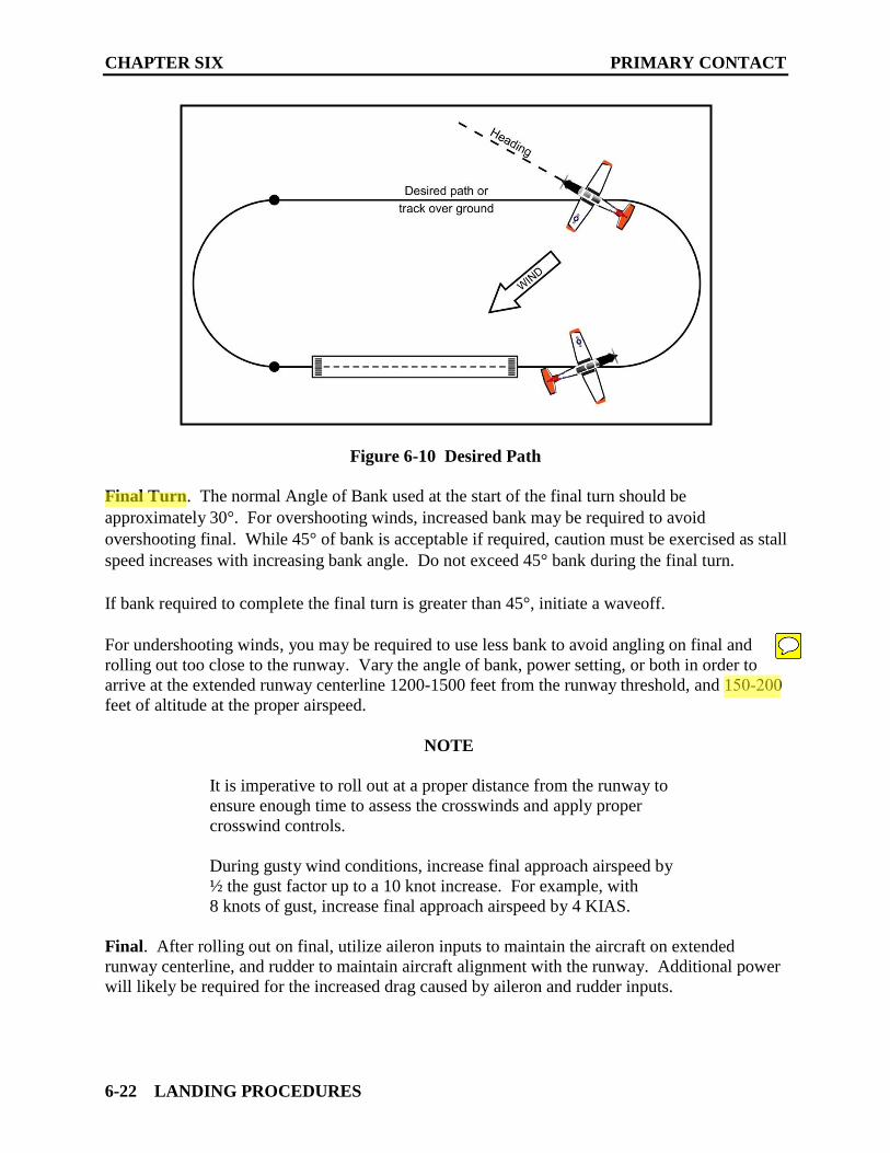
Figure 6-10 Desired Path
Final Turn. The normal Angle of Bank used at the start of the final turn should be
approximately 30°. For overshooting winds, increased bank may be required to avoid
overshooting final. While 45° of bank is acceptable if required, caution must be exercised as stall
speed increases with increasing bank angle. Do not exceed 45° bank during the final turn.
If bank required to complete the final turn is greater than 45°, initiate a waveoff.
For undershooting winds, you may be required to use less bank to avoid angling on final and
rolling out too close to the runway. Vary the angle of bank, power setting, or both in order to
arrive at the extended runway centerline 1200-1500 feet from the runway threshold, and 150-200
feet of altitude at the proper airspeed.
NOTE
It is imperative to roll out at a proper distance from the runway to
ensure enough time to assess the crosswinds and apply proper
crosswind controls.
During gusty wind conditions, increase final approach airspeed by
½ the gust factor up to a 10 knot increase. For example, with
8 knots of gust, increase final approach airspeed by 4 KIAS.
Final. After rolling out on final, utilize aileron inputs to maintain the aircraft on extended
runway centerline, and rudder to maintain aircraft alignment with the runway. Additional power
will likely be required for the increased drag caused by aileron and rudder inputs.
PRIMARY CONTACT CHAPTER SIX
LANDING PROCEDURES 6-23
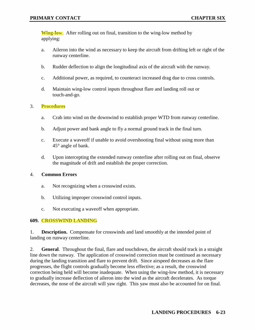
Wing-low. After rolling out on final, transition to the wing-low method by
applying:
a. Aileron into the wind as necessary to keep the aircraft from drifting left or right of the
runway centerline.
b. Rudder deflection to align the longitudinal axis of the aircraft with the runway.
c. Additional power, as required, to counteract increased drag due to cross controls.
d. Maintain wing-low control inputs throughout flare and landing roll out or
touch-and-go.
3. Procedures
a. Crab into wind on the downwind to establish proper WTD from runway centerline.
b. Adjust power and bank angle to fly a normal ground track in the final turn.
c. Execute a waveoff if unable to avoid overshooting final without using more than
45° angle of bank.
d. Upon intercepting the extended runway centerline after rolling out on final, observe
the magnitude of drift and establish the proper correction.
4. Common Errors
a. Not recognizing when a crosswind exists.
b. Utilizing improper crosswind control inputs.
c. Not executing a waveoff when appropriate.
609. CROSSWIND LANDING
1. Description. Compensate for crosswinds and land smoothly at the intended point of
landing on runway centerline.
2. General. Throughout the final, flare and touchdown, the aircraft should track in a straight
line down the runway. The application of crosswind correction must be continued as necessary
during the landing transition and flare to prevent drift. Since airspeed decreases as the flare
progresses, the flight controls gradually become less effective; as a result, the crosswind
correction being held will become inadequate. When using the wing-low method, it is necessary
to gradually increase deflection of aileron into the wind as the aircraft decelerates. As torque
decreases, the nose of the aircraft will yaw right. This yaw must also be accounted for on final.

CHAPTER SIX PRIMARY CONTACT
6-24 LANDING PROCEDURES
Do not level the wings; keep the upwind wing down throughout the flare. Think of flaring over
one wheel. As the forward momentum decreases, the weight of the aircraft will cause the other
main wheel to settle onto the runway. If the wings are leveled prior to touchdown, the airplane
will begin drifting and the touchdown will occur while drifting.
During gusty or high wind conditions, extreme caution should be used to make certain that the
aircraft is not drifting or crabbing. A crab is a condition that occurs when a touchdown is
executed while the longitudinal axis of the aircraft is not aligned with the runway. Since the
aircraft is actually traveling sideways in relation to the runway, it will impart a tipping moment in
the direction that the aircraft is traveling. Touchdown in a crab or drift will also cause the aircraft
to turn away from the intended landing path. This turn is called a swerve. Any time a
swerve develops, centrifugal force will be created commensurate to the speed of the swerve. It is
dangerous to land in a crab or drift and could potentially cause the aircraft to depart the runway.
If unable to apply proper crosswind controls before touchdown, or an uncontrollable drift
occurs during the flare, WAVEOFF!
Full Stop. During the landing roll, special attention must be given to maintaining directional
control with rudders while maintaining crosswind aileron inputs. While the airplane is
decelerating during the landing roll, more and more aileron must be applied to keep the upwind
wing from rising. Since the airplane is slowing down, there is less airflow over the ailerons and
they become less effective. At the same time, the relative wind is becoming more of a crosswind
and exerting a greater lifting force on the upwind wing. Consequently, when the airplane is
coming to a stop, the aileron control must be held fully towards the winds. Maintain directional
control with rudder and/or differential braking while applying aileron deflection into the wind. If
landing occurred off runway centerline, do not attempt to aggressively correct back toward
the center of the runway! If the aircraft becomes uncontrollable after initial touchdown,
WAVEOFF.
Touch-and-Go. Hold crosswind inputs on the deck and apply upwind aileron to maintain a
wings level attitude. Initiate positive (firm) rotation when flying speed is reached to avoid side-
slipping. Initial drift correction is made by turning into the wind with a shallow bank to
counteract drift, then rolling wings-level. On the climbout, it will be necessary to “crab” the
aircraft into the wind to maintain runway heading.
3. Procedures.
a. Maintain crosswind correction through the landing transition using slight
adjustments of rudder and aileron as necessary.
b. Apply rudder as required to align the aircraft with the runway. Increase
aileron pressure as necessary to land the aircraft with zero side motion.
c. Add power as required to maintain proper aimpoint and airspeed due to the increased
drag.
d. Landing will be made on the upwind main mount first.

PRIMARY CONTACT CHAPTER SIX
LANDING PROCEDURES 6-25
e. Maintain crosswind corrections to minimize weathervaning and lower the nose to
the runway.
f. For full stop landings:
i. Increase aileron into the wind as the airplane decelerates.
ii. Use rudder as required to continue straight down the runway.
iii. Smoothly apply brakes below 80 KIAS. Maintain directional control
with rudder and/or brakes while applying aileron deflection into the
wind.
g. For touch-and-go landings:
i. Hold in crosswind controls throughout ground roll.
ii. Advance PCL to MAX.
iii. Rotate the aircraft to the takeoff attitude at 85 KIAS
(minimum).
h. If unable to apply proper crosswind controls before touchdown, or an
uncontrollable drift occurs during the flare, WAVEOFF!
4. Common Errors.
a. Landing with any side motion.
b. Landing in a crab.
c. Not holding in corrections while on the runway.
d. Not executing a waveoff when necessary.
e. Overcorrecting back towards runway centerline.
f. Not increasing aileron deflection into the wind during a full stop.
g. Not crabbing upwind after a touch-and-go, causing a drift from runway centerline.
h. Not checking airspeed before applying brakes.

Change 2 3-5
AIR FORCE TO 1T-6B-1NAVY (NAVAIR) A1-T6BAA-NFM-100
EMERGENCY GROUND EGRESS
NOTEIn a situation requiring immediate groundegress, the ejection system has the capabilityfor 0/0 ejection.
If emergency egress is required on the ground (Figure 3-1),perform the following steps after the aircraft has come to acomplete stop and the engine has been shut down:
*1. ISS mode selector – SOLO
Failure to ensure that the ISS mode selectoris set to SOLO may result in the inadvertentejection of one or both seats.
*2. Seat safety pin – Install (BOTH)
Failure to insert both ejection seat safety pins(if occupied) before ground egress mayresult in inadvertent activation of ejectionsequence and subsequent injury or deathwhen performing emergency ground egress.
*3. PARKING BRAKE – As required
*4. Canopy – Open
IF CANOPY CANNOT BE OPENED OR SITUATIONREQUIRES RIGHT SIDE EGRESS:
*5. CFS handle – Rotate and pull (BOTH)
● If the canopy fracturing system malfunctionsin conjunction with a canopy latch failure inthe locked position, ejection may be the onlyoption remaining to exit the aircraft. Aircrewshall ensure shoulder straps, lap straps, andleg restraint garters are still attached prior topulling ejection handle.
● To prevent injury, ensure oxygen mask is onand visor is down prior to actuating the CFSsystem.
● Each internal CFS handle activates only theCFS charge for the respective transparency.Both internal CFS handles must be activatedin order to fracture both transparencies (ifrequired).
*6. Upper fittings, lower fittings, and leg restraint gar-ters – Release (BOTH)
Actuate leg restraint line quick-release lever on leftside of seat or use individual quick-release connectorson leg restraint garters.
NOTEOxygen hose, emergency oxygen hose, com-munication leads, and anti-G suit hose willpull free while vacating cockpit and legrestraint lines will pull through leg restraintgarter D rings if released with quick-releaselever.
*7. BAT, GEN, and AUX BAT switches – OFF
*8. Evacuate aircraft
TAKEOFF EMERGENCIES
There are several factors which affect the pilot’s decision totakeoff or abort. The decision to takeoff or abort should bebased on the following:
● Runway length and condition, terminal weather con-ditions and area traffic.
● If any system emergency affecting safety of flight isexperienced prior to liftoff, the takeoff should beaborted.
ABORT
If it becomes necessary to abort the takeoff, concentrate onmaintaining aircraft control, specifically directional control,while stopping the aircraft on the remaining runway. Toabort a takeoff, accomplish the following:
*1. PCL – IDLE
*2. BRAKES – AS REQUIRED
Refer to Section II for description of maximum brak-ing.
After a stop which required maximum effortbraking and if overheated brakes are sus-pected, do not taxi into or park in a con-gested area until brakes have had sufficienttime to cool. Do not set parking brake.
BARRIER ENGAGEMENT
Aircrews will not call for a raised barrier in the event of anaborted takeoff. If a raised barrier is already up, aircrews
Change 2 3-7
AIR FORCE TO 1T-6B-1NAVY (NAVAIR) A1-T6BAA-NFM-100
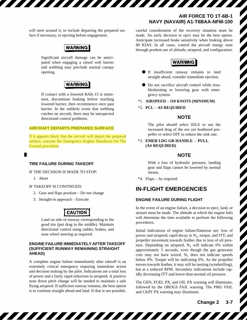
will steer around it, to include departing the prepared sur-face if necessary, or ejecting before engagement.
Significant aircraft damage can be antici-pated when engaging a raised web barrierand webbing may preclude normal canopyopening.
If contact with a lowered BAK-15 is immi-nent, discontinue braking before reachinglowered barrier, then recommence once pastbarrier. In the unlikely event that webbingcatches on aircraft, there may be unexpecteddirectional control problems.
AIRCRAFT DEPARTS PREPARED SURFACE
If it appears likely that the aircraft will depart the preparedsurface, execute the Emergency Engine Shutdown On TheGround procedure.
TIRE FAILURE DURING TAKEOFF
IF THE DECISION IS MADE TO STOP:
1. Abort
IF TAKEOFF IS CONTINUED:
2. Gear and flaps position – Do not change
3. Straight-in approach – Execute
Land on side of runway corresponding to thegood tire (put drag in the middle). Maintaindirectional control using rudder, brakes, andnose wheel steering as required.
ENGINE FAILURE IMMEDIATELY AFTER TAKEOFF (SUFFICIENT RUNWAY REMAINING STRAIGHT AHEAD)
A complete engine failure immediately after takeoff is anextremely critical emergency requiring immediate actionand decision making by the pilot. Indications are a total lossof power and a fairly rapid reduction in airspeed. A positivenose down pitch change will be needed to maintain a safeflying airspeed. If sufficient runway remains, the best optionis to continue straight ahead and land. If that is not possible,
careful consideration of the recovery situation must bemade. An early decision to eject may be the best option.Anticipate increased brake sensitivity when braking above80 KIAS. In all cases, control the aircraft energy statethrough prudent use of altitude, airspeed, and configuration.
● If insufficient runway remains to landstraight ahead, consider immediate ejection.
● Do not sacrifice aircraft control while trou-bleshooting or lowering gear with emer-gency system.
*1. AIRSPEED – 110 KNOTS (MINIMUM)
*2. PCL – AS REQUIRED
NOTEThe pilot should select IDLE to use theincreased drag of the not yet feathered pro-peller or select OFF to reduce the sink rate.
*3. EMER LDG GR HANDLE – PULL(AS REQUIRED)
NOTEWith a loss of hydraulic pressure, landinggear and flaps cannot be lowered by normalmeans.
*4. Flaps – As required
IN-FLIGHT EMERGENCIES
ENGINE FAILURE DURING FLIGHT
In the event of an engine failure, a decision to eject, land, orairstart must be made. The altitude at which the engine failswill determine the time available to perform the followingprocedures.
Initial indications of engine failure/flameout are: loss ofpower and airspeed; rapid decay in N1, torque, and ITT; andpropeller movement towards feather due to loss of oil pres-sure. Depending on airspeed, N1 will indicate 0% withinapproximately 5 seconds, even though the gas generatorcore may not have seized. N1 does not indicate speedsbelow 8%. Torque will be indicating 0%. As the propellermoves towards feather, it may still be turning (windmilling),but at a reduced RPM. Secondary indications include rap-idly decreasing ITT and lower-than-normal oil pressure.
The GEN, FUEL PX, and OIL PX warning will illuminate,followed by the OBOGS FAIL warning. The PMU FAILand CKPT PX warning may illuminate.

2-28 Change 4
AIR FORCE TO 1T-6B-1NAVY NAVAIR A1-T6BAA-NFM-100
To avoid possible contact of ventral fin withrunway, do not allow the aircraft to developexcessive sink rates or allow excessive nose-high pitch attitudes during landing. No-flaplandings with excessive sink rates greatlyincrease the likelihood of tail strikes.
If nose wheel shimmy occurs after the nose wheel contactsthe runway, apply back stick pressure to relieve the weighton the nose wheel, then gently release pressure to reestablishnose wheel contact with the runway. Notify maintenanceafter the mission.
Use rudder and ailerons to maintain directional control. Con-tinue to apply brakes as required, but avoid differential brak-ing during high speed portion of landing rollout. N1 willautomatically reduce from flight idle (67%) to ground idle(60-61%), approximately 4 seconds after touchdown.
Engaging nose wheel steering during shimmymay damage the actuator and result in a steer-ing "hard over" event and loss of directionalcontrol. Do not engage nose wheel steeringduring landing rollout in attempt to dampennose wheel shimmy.
Engage nose wheel steering as required once taxi speed isachieved.
• If one brake fails, use the other brake and rud-der/ailerons to aid in maintaining directionalcontrol. If both cockpits are occupied, thepilot with effective brakes shall assume brak-ing authority. If directional control cannot bemaintained, execute Aircraft Departs Pre-pared Surface procedure.
• Neutralize rudder pedals prior to engagingnose wheel steering to avoid excessiveswerve when nose wheel steering is selected.
TOUCH AND GO LANDING
Upon touchdown, smoothly advance the PCL to MAX.Anticipate a slight amount of right rudder as torqueincreases. Rotate at rotation speed.
The landing gear may be left down when remaining in thepattern, but the pilot must observe the maximum gearextended speed in Section V. After liftoff, proceed with theAfter Takeoff checklist.
CROSSWIND LANDING
Crosswind landings require only a slight adjustment of land-ing technique. Crab as necessary while in the pattern toaccommodate crosswind component. Once transitioned tofinal, establish a wing low attitude into the wind to counterdrift, and maintain runway alignment with rudder. Maintainthe wing low attitude and rudder input throughout the flare.
GUSTY WIND LANDING
During gusty wind conditions, increase landing thresholdand touchdown speeds by 50% of the gust increment up to amaximum increase of 10 knots. LDG flaps are not recom-mended during gusty wind conditions.
ANGLE OF ATTACK (AOA) LANDING
Angle of attack (AOA) landings utilize the normal landingpattern in Figure 2-8 or Figure 2-9 while maintaining opti-mum AOA throughout the final/approach turn. On down-wind, slow to optimum AOA (on-speed amber donut onindexer) prior to the perch/abeam position. After the perch/abeam position, maintain on-speed AOA with pitch andmaintain controlled descent rate with power. Maintain anappropriate angle of bank and line up on runway centerline.On final, coordinate stick and power inputs to land at desiredtouchdown point while continuing to fly on-speed AOA.Round out and touch down normally.
MAXIMUM BRAKING
Maximum braking effectiveness is obtained with a steadyapplication of brakes.
The physical limitations of the tire and brake system make itextremely difficult to consistently achieve maximum brak-ing action, particularly at high speeds where the weight com-ponent is reduced due to lift. A smooth, single application,increasing as airspeed decreases, offers the best brakingopportunity. Great caution should be used when braking atspeeds above 80 KIAS. Locked brakes are difficult to diag-nose until well after the fact. Braking should be discontinuedat the first sign of directional control problems and then cau-tiously reapplied. At speeds below 80 KIAS, the chances ofapproaching maximum braking action are greatly increased.

JPPT 1542.166A C2103
CFS and Ejection procedures from the ground
• A little bit of crew coordination will go a long way as far as safety is concerned if faced with using CFS during ground operations. The idea is coordinating the “CFS – Rotate and Pull” if using the internal CFS handles between front and rear cockpits. There a few techniques to accomplish this task and will be briefed between crewman during the NATOPS preflight brief prior to flight.
• If required, right side egress is possible with use of CFS - ensure oxygen mask is on and visor is down prior to actuating the CFS system. Internal CFS handles activate CFS charge for the respective transparency. External CFS handles activate both CFS charges for each cockpit.
• In a situation (e.g., fire or imminent collision) requiring immediate ground egress, the ejection
system affords a 0/0 ejection capability.
• You should ensure the canopy is going to open before un-strapping (i.e., ensure that it is not jammed by the incident that has led to your Emergency Ground Egress) so as to still be able to eject, should that option of egress need to be exercised.
A3-2
AIR FORCE TO 1T-6B-1NAVY (NAVAIR) A1-T6BAA-NFM-100
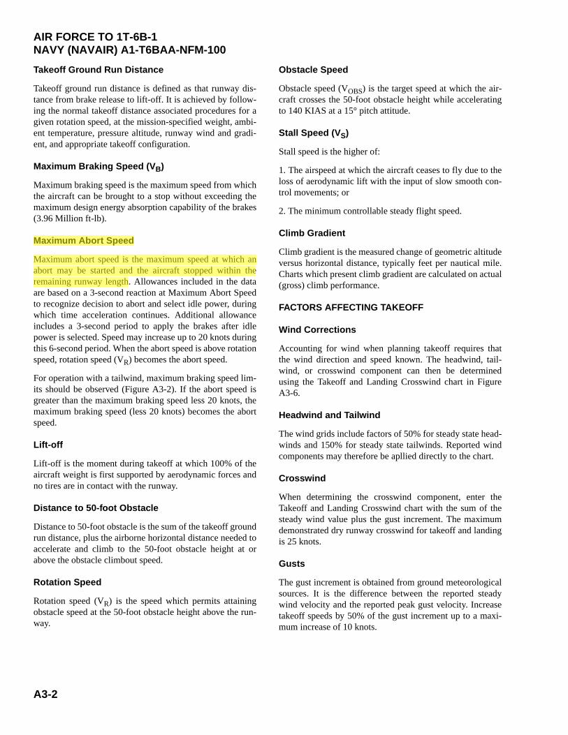
Takeoff Ground Run Distance
Takeoff ground run distance is defined as that runway dis-tance from brake release to lift-off. It is achieved by follow-ing the normal takeoff distance associated procedures for agiven rotation speed, at the mission-specified weight, ambi-ent temperature, pressure altitude, runway wind and gradi-ent, and appropriate takeoff configuration.
Maximum Braking Speed (VB)
Maximum braking speed is the maximum speed from whichthe aircraft can be brought to a stop without exceeding themaximum design energy absorption capability of the brakes(3.96 Million ft-lb).
Maximum Abort Speed
Maximum abort speed is the maximum speed at which anabort may be started and the aircraft stopped within theremaining runway length. Allowances included in the dataare based on a 3-second reaction at Maximum Abort Speedto recognize decision to abort and select idle power, duringwhich time acceleration continues. Additional allowanceincludes a 3-second period to apply the brakes after idlepower is selected. Speed may increase up to 20 knots duringthis 6-second period. When the abort speed is above rotationspeed, rotation speed (VR) becomes the abort speed.
For operation with a tailwind, maximum braking speed lim-its should be observed (Figure A3-2). If the abort speed isgreater than the maximum braking speed less 20 knots, themaximum braking speed (less 20 knots) becomes the abortspeed.
Lift-off
Lift-off is the moment during takeoff at which 100% of theaircraft weight is first supported by aerodynamic forces andno tires are in contact with the runway.
Distance to 50-foot Obstacle
Distance to 50-foot obstacle is the sum of the takeoff groundrun distance, plus the airborne horizontal distance needed toaccelerate and climb to the 50-foot obstacle height at orabove the obstacle climbout speed.
Rotation Speed
Rotation speed (VR) is the speed which permits attainingobstacle speed at the 50-foot obstacle height above the run-way.
Obstacle Speed
Obstacle speed (VOBS) is the target speed at which the air-craft crosses the 50-foot obstacle height while acceleratingto 140 KIAS at a 15° pitch attitude.
Stall Speed (VS)
Stall speed is the higher of:
1. The airspeed at which the aircraft ceases to fly due to theloss of aerodynamic lift with the input of slow smooth con-trol movements; or
2. The minimum controllable steady flight speed.
Climb Gradient
Climb gradient is the measured change of geometric altitudeversus horizontal distance, typically feet per nautical mile.Charts which present climb gradient are calculated on actual(gross) climb performance.
FACTORS AFFECTING TAKEOFF
Wind Corrections
Accounting for wind when planning takeoff requires thatthe wind direction and speed known. The headwind, tail-wind, or crosswind component can then be determinedusing the Takeoff and Landing Crosswind chart in FigureA3-6.
Headwind and Tailwind
The wind grids include factors of 50% for steady state head-winds and 150% for steady state tailwinds. Reported windcomponents may therefore be apllied directly to the chart.
Crosswind
When determining the crosswind component, enter theTakeoff and Landing Crosswind chart with the sum of thesteady wind value plus the gust increment. The maximumdemonstrated dry runway crosswind for takeoff and landingis 25 knots.
Gusts
The gust increment is obtained from ground meteorologicalsources. It is the difference between the reported steadywind velocity and the reported peak gust velocity. Increasetakeoff speeds by 50% of the gust increment up to a maxi-mum increase of 10 knots.


Ejection Seat Sequencing Mitigation Contingencies
• FCP Incapacitation1. ISS Mode Selector – BOTH2. RCP – Eject
• ICS Failure• “Face curtain” signal serves as the prepatory command
during a controlled ejection. A thumbs up from eachoccupant is required to initiate ejection sequence.
• FCP shall initiate ejection sequence with three “raps” ofthe canopy
• RCP occupant shall initiate ejection ON third “rap”• FCP occupant shall initiate ejection NET ~0.5 seconds
AFTER third “rap”
Misc • Unqualified personnel prohibited
• Must be NATOPS qualified, enrolled in a formal aviation syllabus, or an observer qualified Naval Flight Officer, Flight Surgeon, or AeromedicalSafety Officer
• Delaying ejection below 2,000 ft AGL is notrecommended
• Any delays may negatively impact theejection envelope
• FCP occupant initiates ejection NET ~0.5 secAFTER third “EJECT” call or immediately afterconfirming the RCP occupant has ejected
• Proper manual ejection sequencing requiresthe RCP occupant to eject prior to the FCPoccupant
CRM • RCP Delaying Ejection
• May lead to collision with FCP seat• RCP shall not hesitate or delay ejecting• RCP occupant shall initiate ejection ON third “EJECT” call
• FCP Initiating Ejection Too Soon• May lead to collision with RCP seat• FCP shall initiate ejection NET ~0.5 sec after third
“EJECT” call
Procedures • Dual Flights
• ISS Mode Selector – SOLO in flight (Before Takeoff checks)• RCP occupant shall initiate ejection ON third “EJECT” call• FCP occupant shall initiate ejection NET ~0.5 sec AFTER
third “EJECT” call
• Solo Flights• Normal NATOPS Procedures Apply• Ensure ISS Mode Selector is in SOLO