Embed Size (px)
DESCRIPTION
Manual Ssangyong korando
Citation preview

03-33660-01
1. ABBREVIATIONNo Abbreviation Name
1 DTC Diagnostic trouble code
2 TCU Transmission control unit
3 ATF Automatic transmission fluid
4 DC Damper clutch
5 PCSV Pressure control solenoid valve
6 UD Under drive
7 OD Over drive
8 LR Low reverse
9 LP Line pressure
10 SOL Solenoid
11 VFS Variable force solenoid
12 PG-A Input speed sensor
13 PG-B Output speed sensor

03-4
2. GENERAL INFORMATIONAutomatic transaxle (6F24)▶
The Model 6F24 six speed automatic transaxle is available in two variants: four wheel drive and two wheel drive.
Six forward speedsOne reverse gearA toruqe converter with an integral converter lock-up clutch with slip control capabilitiesPlanetary gear-set (3EA)Clutches (2EA)Brake (3EA)O.W.C (1EA) All hydraulic functions are directed by electronic solenoids to control:
---
-----
Engagement feelShift feelShift schedulingModulated torque converter clutch applications
1)2)3)4)
Inhibitor switch
Oil panTorque converter
TCU (located under driver's seat)▶
TCU is located under the driver's seat and controls the transaxle operations.TCU receives and uses the signals from sensors and switches through CAN bus with analog and digital types.
E-coupling unit
TCU

03-53660-01
The shiftable gear can be adjusted by pressing the "UP (D+)" or "DOWN(D-)" switch when the gear selector lever is in “M” position.
Shift lock release buttonIf the selector lever cannot be moved from “P” or “N” position, try to move the lever
while pushing down this button with finger. For safety, turn off the engine and depress the brake pedal before the attempt.
Shift upShift down
Tip switches on steering wheel▶ Meter cluster▶
This indicator shows the current position of the gear.
Gear selector lever▶
Lever positionsP : ParkR : reverseN : NeutralD : Drive
Tip switch (manual shift switch)The shiftable gear can be adjusted by moving this switch to forward and rearward when the gear selector lever is in “M”
position.
Selection of Manual/Automatic Shift FunctionD: Automatic shift according to the driving conditionM: Manual shift

03-6
3. SPECIFICATIONS1) Specifications
Type/Weight 6F24 6-speed automatic transaxle /approx. 86 kg (including ATF)
TORQUE 230 Nm
Overall length / Center length 373.1 mm / 204 mm
Descriptions Specification
Gear ratio 1st gear 4.212
2nd gear 2.637
3rd gear 1.800
4th gear 1.386
5th gear 1.000
6th gear 0.772
Reverse gear 3.385
Shift pattern Variable
Shift range 4 Range (P-R-N-D) + Manual mode
Shift range valve VFS : 6EA
Planetary gear 3EA (Front, Middle, Rear)
Clutch 2EA
Brake 3EA
O.W.C 1EA
Oil Type ATF SP-IV M
Capacity approx. 7.1 L
Change interval Maintenance free. However, under the severe conditions or commercially used, change the oil at
every 100,000 km (EU: 90,000 km).
Resistance of oil temperature sensor
-20 Approx 15.6kΩ
0 Approx 5.88kΩ
20 Approx 2.51kΩ
100 Approx 0.18kΩ
Weight 2WD 87.5kg
4WD 88.5kg

03-73660-01
4. COMPONENTS
HPT 6A/T (6F24)
One-way clutch Torque converter(with slip lockup)
Oil pumpHarness
Valve body Side gear Driven gear

03-8
Automatic transaxle Bolt (engine) 17 mm X 4 14 mm X 1
85.0 ~ 100.0Nm
Bolt (start motor) 14 mm X 2 48.0 ~ 58.8Nm
Bolt (oil pan) 14 mm X 4 56.0 ~ 62.0Nm
Bolt (torque converter) 17 mm X 6 45.0 ~ 52.0Nm
Eye bolt 22 mm X 1 3.0 ~ 5.0Nm
Drain plug 24 mm X 1 34.0 ~ 44.0Nm
Nut (range select lever) 14 mm X 1 17.6 ~ 24.5Nm
Bolt (inhibitor switch) 10 mm X 2 9.8 ~ 11.7Nm
Bolt (oil pan) 10 mm X 19 12.0 ~ 14.0Nm
Bolt (solenoid harness) 10 mm X 6 9.8 ~ 11.7Nm
Bolt (oil temperature sensor) 10 mm X 1 9.8 ~ 11.7Nm
Bolt (input & output sensor) 10 mm X 2 9.8 ~ 11.7Nm
Bolt (detent spring) 12 mm X 1 12.0 ~ 16.0Nm
Bolt (valve body) 10 mm X 8 9.8 ~ 11.7Nm
Bolt (V/B solenoid bracket) H5 mm X 9 9.8 ~ 11.7Nm
Bolt (torque converter housing) 12 mm X 20 28.0 ~ 35.0Nm
Bolt (oil guide A) 10 mm X 3 9.8 ~ 11.7Nm
Bolt (oil guide B) 10 mm X 1 5.0 ~ 7.0Nm
Bolt (oil filter) H5 mm X 2 9.8 ~ 11.7Nm
5. TIGHTENING TORQUE
Descriptions Size x Numbers
Tightening torque (Nm)
TGS lever Nut 12 mm X 4 17.6 ~ 21.6Nm
Nut (manual control lever) 13 mm X 1 14.0 ~ 20.0Nm
Nut (floor) 12 mm X 1 17.6 ~ 21.6Nm
Nut (dash panel) 12 mm X 2 17.6 ~ 21.6Nm
A/T bracket Bolt (left bracket) 17 mm X 3 88.2 ~ 107.8Nm
Bolt (right bracket) 17 mm X 4 88.2 ~ 107.8Nm
Bolt (upper bracket) 17 mm X 4 88.2 ~ 107.8Nm
TGS lever
TGS cable

03-93660-01
Descriptions Size x Numbers
Tightening torque (Nm)
Automatictransaxle
Bolt (oil lubrication pipe) 10 mm X 1 9.8 ~ 11.7Nm
Bolt (oil pump) 12 mm X 7 20.0 ~ 26.0Nm
Bolt (parking rod guide) 10 mm X 2 9.8 ~ 11.7Nm
Bolt (U/D brake retainer) T40 X 6 31.0 ~ 36.0Nm
Bolt (U/D brake chamber) T30 X 2 4.9 ~ 9.8Nm
Bolt (rear cover) 12 mm X 13 28.0 ~ 35.0Nm

03-10
6. SPECIAL SERVICE TOLLSPart number Name Tool How to use
00104-001(UD) Remover & Installer - U/D brake return sprin
00104-002(OD) Remover& Installer - O/D clutch return spring
00104-003(LR)(use with 00104-001)
Remover& Installer - L/R brake return spring
* Special service tool Supplier: Tool & Tech

03-113660-01
1. OVERVIEW2WD 4WD
The Model 6F24 6 speed automatic transaxle is electronically controlled. The control system is comprised of the following components:
External transaxle control unit (TCU)Input and output speed sensorsSix variable force solenoids(VFS) and two on/off solenoidsTorque converterATF temperature sensor
-----
TCU controls the oil pressure for various internal clutches and brakes to select the gear. It also controls the electronic elements, shift pressure and torque converter slip. If the system is defective, TCU provides FMEC (Failure Mode Effect Control) to maintain the functionality of transaxle. This keeps the basic function of transaxle (gear selection) even when there are failure in controls and power supply.
There are selector shaft position sensor (inhibitor switch) and oil temperature sensor in transaxle. In manual mode, TCU receives the information from TGS (Transmission Gear Selector) through PCB (Printed Circuit Board) when driver selects the manual shift mode. TCU communicates with other electric control modules through CAN. In order to ensure a safe driving state and to prevent damage to the automatic transmission, TCU switches to Limp-Home mode in the event of critical faults.

03-12
2. FEATURES
1) AdvantagesEarly Downshift with Hard Braking and Skip Shifts▶
When heavy braking is detected, the transaxle downshifts early and skips gears to provide increased engine braking to provide gear selection for tip-in.
Gear Hold going Uphill/Downhill▶
If the accelerator pedal is released when traveling uphill, upshifts are prevented to reduce busyness on grades. If the accelerator pedal is released when traveling downhill, upshifts are prevented to enhance engine braking.
Drive and Reverse Engagement▶
A soft engagement feature avoids harsh take up of drive when selecting Drive or Reverse. This is achieved by limiting engine speed and engine torque which results in a rapid, but progressive engagement of either Drive or Reverse when moving from the Park or Neutral positions. Drive and Reverse engagements from either Park or Neutral are performed in less than 2.2 seconds. There is no drive engagement prevention strategy implemented on the transaxle system as there is sufficient engine strategy to protect the system. However, reverse engagement is prevented until vehicle speed is less than 7 km/h.

03-133660-01
2) Transaxle CoolingThe transaxle cooling system ensures rapid warm-up and constant operating temperature resulting in reduced fuel consumption and refined shift quality.It also includes a cooler by-pass within the hydraulic system to allow sufficient lubrication to the transaxle drivetrain in the event of a blockage in the transaxle cooler.
3) Shift StrategyGear Change▶
Transaxle gear change is controlled by the TCU. The TCU receives inputs from various engine and vehicle sensors to select shift schedules and to control the shift feel and torque converter clutch (TCC) operation at each gear change.
Coast down▶
Coast down down shifts occur at 0% pedal when the vehicle is coasting down to a stop.
Torque Demand▶
Torque demand down shifts occur (automatically) when the driver demand for torque is greater than the engine can provide at that gear ratio. If applied, the transaxle will disengage the TCC to provide added acceleration.

03-14
3. MODES AND FUNCTIONSThis allows the driver to define the highest possible gear by selecting “+” or “-” on the
gear selector when the lever is in the “M”
position. When the lever is first moved to the manual “M” position the transaxle will select
one lower gear than current gear.
When driving on a slippery road, push the tip switch forward into the "+" position in "M" position. This causes the transaxle to shift into the 2nd gear which is better for smooth driving on a slippery road.

03-153660-01
1st Gear State▶
The 1st gear state will display on the instrument cluster. Unlike the normal 1st gear, engine braking will be available in this manual 1st state.
-
2nd Gear State▶
The 2nd gear state will display on the instrument cluster. 2nd gear has engine braking available.
-
3rd Gear State▶
The 3rd gear state will display on the instrument cluster. 3rd gear has engine braking available.
-
4th Gear State▶
The 4th gear state will display on the instrument cluster. 4th gear has engine braking available.
-
5th Gear State▶
The 5th gear state will display on the instrument cluster. 5th gear has engine braking available.
-
6th Gear State▶
The 6th gear state will display on the instrument cluster. 6th gear has engine braking available.
-
STD type
SVC type

03-16
4. LIMP HOME MODEWhen the transaxle is defective▶
In the event of a system fault, the TCU also provides for failure mode effect control (FMEC) to maintain maximum functional operation of the transaxle. (There are 3 FMEC modes, mechanical limp-home mode, electrical limp-home mode, limp-home mode C.)In the event of a total loss of control or electrical power, the basic transaxle functions (Park, Reverse, Neutral and Drive) are retained. The 4th and reverse gear ratios with the torque converter clutch in the unlocked state are the retained gear states the hydraulic system supports without any electrical assistance. (Mechanical limp-home)If the speed sensor circuit is failed, the gear is fixed to 4th gear, but manual shifting (2nd↔3rd↔4th) is available.(Electrical limp home mode)
If the inhibitor switch signals are invalid, shifting to1st and 2nd gear is forbidden. (Limp-home C)The TCU communicates with other vehicle electronic control modules by the controller area network (CAN). If a major fault is developed, the transaxle may not accomplish the intelligent shift control. The TCU controls the transaxle with preset values.The TCU also provides for transaxle diagnostics, which meet the requirements of OBD II regulation, monitoring all components which may effect vehicle emissions.
1.
2.
3.
4.5.
6.
Towing the automatic transaxle equipped vehicle▶
Flat-bed equipment is the best method of moving a disabled vehicle to avoid any damages. For AWD vehicle: The vehicle must be towed with a wheel lift and dollies or flatbed equipment with all the wheels off the ground.For 2WD vehicles: It is acceptable to tow the vehicle with the rear wheels on the ground without dollies and the front wheels off the ground. When being towed by a commercial towtruck and wheel dollies are not available, the front of the vehicle should be lifted, not the rear.
--

03-173660-01
5. TRANSAXLE ELECTRONIC CONTROL SYSTEM1) General InformationThe transmission control unit (TCU) and its input/output network control the following transmission operations:
Shift timingLine pressure Clutch pressure (shift feel)Torque converter clutch
----
also uses these signals when determining transaxle operating strategy. Using all of these input signals, the TCU can determine when the time and conditions are right for a shift, or when to apply or release the torque converter clutch. It will also determine the pressure needed to optimise shift feel.
2) TCU (Transmission Control Unit)The transaxle control unit (TCU) is mounted under the driver's seat and controls the operation of the transaxle.Internal sensors and signals received across the CAN bus in analogue and digital forms such as:
Transaxle input speedTransaxle output speedAccelerator pedal positionGear selector positionEngine torqueEngine speedTransaxle fluid temperatureBrake pedal statusEngine oil temperatureEngine coolant temperatureAmbient air temperatureBarometric pressure
------------
The TCU monitors all TCU inputs and outputs to confirm correct system operation. If a fault occurs the TCU is able to perform default action and inform the driver of the problem through the instrument cluster warning lights. Detailed information is available via trouble codes which can be read with the service tool.
03-18
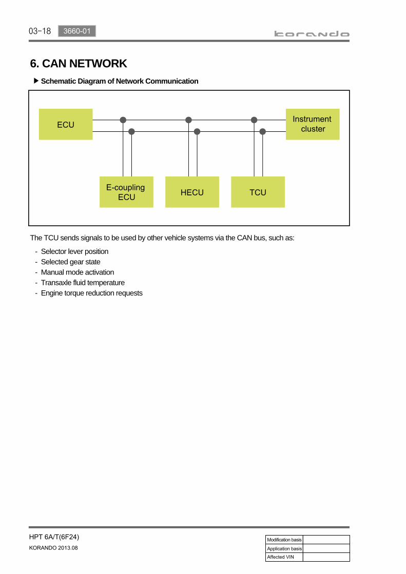
6. CAN NETWORK
The TCU sends signals to be used by other vehicle systems via the CAN bus, such as:
Selector lever positionSelected gear stateManual mode activationTransaxle fluid temperatureEngine torque reduction requests
-----
Schematic Diagram of Network Communication▶

03-193660-01
7. POWER TRANSFERPower transfer modes are as follow:
Manual: 1st gear (position M)Drive: 1st gearDrive: 2nd gearDrive: 3rd gearDrive: 4th gear - limp home modeDrive: 5th gearDrive: 6th gear
-------
1) Overview
Name Component
C1 OVER DRIVE CLUTCH
C2 35R CLUTCH
B1 LOW & REVERSE BRAKE
B2 2/6 BRAKE
B3 UNDER DRIVE BRAKE
1F 1-2 ONE WAY CLUTCH
GEARCLUTCH BRAKE
OWC Gear RatioOD 35R 26 LR UD
1ST △* O O 4.212
2ND O O 2.637
3RD O O 1.800
4TH O O 1.386
5TH O O 1.000
6TH O O 0.772
REV O O 3.385
N.P O
(1) Gear Selection and Engagement Element
Operation when vehicle speed under 5kph*

03-20
2) Operation in Each Gear Position(1) Neutral/Park
Lower & reverse brake (LR/B) operated → Overdrive (O/D) hub locked → Middle & rear (MID &
REAR) P/C lockedInput shaft rotated → Rear sun gear rotated → Rear inner pinion reverse rotated → Rear outer
pinion rotated → Rear annulus gear rotated → Front annulus gear rotated → Front pinion
rotated → Front sun gear reverse rotated → Underdrive (U/D) hub reverse rotated
Input shaft rotated → Overdrive clutch (OD/C) retainer rotated
Input shaft rotated → 35R clutch rotated
-
-
--
Power flow▶
Description 35R C OD C 26 B UD B LR B O.W.C
P.N ●

03-213660-01
(2) Reverse (3.385)
Middle planetary gear locked, middle sun gear rotated When the sun gear rotates with the planetary gear locked in middle planetary gear set, the annulus gear (front planetary gear) rotates in reverse direction with decreased speed and the power flows through the front planetary gear. The rear planetary gear set reduces the rotating speed of rear & front annulus gears and the front planetary gear set rotates the front sun gear in reverse direction without load.
--
-
Power flow▶
Description 35R C OD C 26 B UD B LR B O.W.C
R ● ●

03-22
(3) 1st Drive Gear (4.212)
Front sun gear and middle & rear planetary gears locked, and rear sun gear always rotatedWhen the rear sun gear rotates, the rear planetary gear set reduces the speed at first, and then the reduced power is transferred to rear & front annulus gear. The power is secondarily reduced at front planetary gear locked with sun gear and flows to front planetary gear. At this moment, the middle sun gear rotates in reverse direction without load (idling) by the rotation of middle annulus gear integrated with front planetary gear.
--
-
Power flow▶
Description 35R C OD C 26 B UD B LR B O.W.C
1ST ● ○ ●
Operated below 5 km/h of vehicle speedO :

03-233660-01
(4) 2nd Drive Gear (2.637)
Front sun gear and middle sun gear locked, rear sun gear always rotatedWhen the sun gear rotates, the power is transferred to the rear & front annulus gears, and then the reaction power from the front planetary gear and middle annulus gear locked with sun gear is transferred to middle & rear planetary gear to circulate the power. Accordingly, the power flows through the front planetary gear while keeping the balance.
--
Power flow▶
Description 35R C OD C 26 B UD B LR B O.W.C
2nd ● ●

03-24
(5) 3rd Drive Gear (1.800)
Front sun gear locked, middle & rear sun gear rotated When the middle sun gear and rear sun gear rotate, the power is transferred to the rear & front annulus gears, and then the reaction power from the front planetary gear and middle annulus gear locked with sun gear is transferred to middle & rear planetary gear to circulate the power. Accordingly, the power flows through the front planetary gear while keeping the balance.
--
Power flow▶
Description 35R C OD C 26 B UD B LR B O.W.C
3rd ● ●

03-253660-01
(6) 4th Drive Gear (1.386)
Front sun gear locked, rear planetary gear and rear sun gear rotatedWhen the overdrive clutch (OD/C) operates, the carrier is engaged with sun gear in rear planetary gear set and the power with 1:1 ratio flows to the front planetary gear locked with sun gear after passing through the rear & front annulus gears. At this moment, by operation of speed-reduced annulus gears and carrier in 1:1 ratio, the middle sun gear in middle planetary gear set increases its speed without load (idling).
--
-
Power flow▶
Description 35R C OD C 26 B UD B LR B O.W.C
4th ● ●

03-26
(7) 5th Drive Gear (1.000)
Middle & rear planetary gears, middle sun gear and rear sun gear rotatedThe rotating ratio of 1;1 is transferred to middle annulus gear (front planetary gear) because the middle planetary gear and sun gear in middle planetary gear set rotate simultaneously.At this moment, the rear planetary gear set rotates in 1:1 ratio (same in 4th gear). However, the front planetary gear set is not related to that, and the front sun gear rotates without load (idling) in 1:1 ratio.
--
-
Power flow▶
Description 35R C OD C 26 B UD B LR B O.W.C
5th ● ●

03-273660-01
(8) 6th Drive Gear (0.722)
Middle planetary gear rotated, middle sun gear lockedWhen the sun gear is locked in middle planetary gear set and the planetary gear rotates, the middle annulus gear increases the speed and the power is transferred to front planetary gear. The rear planetary gear set rotates in 1;1 ratio (same in 4th & 5th gears). However, the front planetary gear set is not related to that, and the front sun gear increases its speed without load (idling).
--
-
Power flow▶
Description 35R C OD C 26 B UD B LR B O.W.C
6th ● ●


