Embed Size (px)
Citation preview

111/12/2010
C2000™ 32-bit MCU Family
High Performance MCUs forReal-Time Control in Cost-Sensitive Applications

Agenda: TMS320C2000
C2000 Overview• Value Proposition• Target Applications• Architecture & Key Features• Product Portfolio
– PiccoloTM
– DelfinoTM
How to Get Started• controlSUITE• controlCARD Concept• Application Developer’s Kits• Piccolo controlSTICK• Software Libraries & Examples• 3rd Party Solutions & Additional Resources
2

3
Software & Dev. ToolsMPUs – Microprocessors
Embedded processing portfolio
32-bit ARMCortex™-M3
MCUs
16-bit ultra-low power
MCUs
DSPDSP+ARM
ARM Cortex-A8
MPUs
UltraLow-power
DSPs
Stellaris®
ARM® Cortex™-M3 C5000™MSP430™Sitara™
ARM® Cortex™-A8& ARM9
C6000™
DaVinci™
TI Embedded Processors
Digital Signal Processors (DSPs)Microcontrollers (MCUs) ARM®-Based Processors
Video processors
OMAP™
Up to 100 MHz
Flash8 KB to 256 KB
USB, ENET MAC+PHYCAN, ADC, PWM, SPI
Connectivity, Security,Motion Control, HMI,Industrial Automation
$1.00 to $8.00
300MHz to >1GHz
Cache, RAM, ROM
USB, CAN,PCIe, EMAC
Industrial computing, POS & portable data terminals
$5.00 to $20.00
Up to 25 MHz
Flash1 KB to 256 KB
Analog I/O, ADCLCD, USB, RF
Measurement,Sensing, General
Purpose
$0.25 to $9.00
Up to 300 MHz+Accelerator
Up to 320KB RAMUp to 128KB ROM
USB, ADC McBSP, SPI, I2C
Port. Telecom, audio, medical monitor & diag, industrial
$3.00 to $10.00
300MHz to >1GHz+Accelerator
CacheRAM, ROM
USB, ENET, PCIe, SATA, SPI
Floating/Fixed PointVideo, Audio, Voice,
Security, Conferencing
$5.00 to $200.00
32-bit real-time
MCUs
C2000™
Delfino™
Piccolo™
40MHz to 300 MHz
Flash, RAM16 KB to 512 KB
PWM, ADC, CAN, SPI, I2C
Motor Control, Digital Power,
Lighting, Ren. Enrgy
$1.50 to $20.00
Multi-coreDSP
C6000™
24.000 MMACS
CacheRAM, ROM
SRIO, EMACDMA, PCIe
Telecom test & meas., media gateways, base stations
$40 to $200.00
3

4
Thinking MCU? Think TI
Lowest PowerCortex M3
Scalable MCU’sHigh Performance
C2000
High performance core + Analog MCU starting at <$2.00
Up to 300 MHz Floating Point
Over 80 MCU’s
12.5MSPS A/D, High Resolution PWM, Internal Oscillator
Serial, CAN, LIN, EMIF
Accelerated design with <$40.00 tools, plus complete reference design kits for multiple apps
We offer the most breadth & depth in Microcontrollers
MSP430
World’s lowest power MCU
RTC modes in 100’s of nA
Active power at 160uA/MHz
Over 200 MCU’s
High performance integration: A/D, Opamps, LCD Control, DAC
SPI, I2C, UART/LIN, and now with
USB & RF
Starter tools as low as $20.00
Full peripheral explorer kits only $149.00
Stellaris M3
The world’s largest Cortex M3 MCU portfolio
Over 169 MCU’s
A/D’s, Motor Control Hardware, Precision Oscillator, RTC
CAN, I2S, Ethernet MAC & PHY, USB H/D/OTG, EPI
Complete Eval tools <$100.00Full reference designs
Complete software & driver libraries
4

What is C2000?
• DSP performance within a Microcontroller architecture
– 40-300MHz C28x CPU• Built-in DSP functions• Single Cycle 32x32-bit MAC
– Control Law Accelerator
– Floating-Point Unit
– Embedded Flash
• Fine-tuned for real-time control– Optimized core
– Fast interrupts
– Flexible interrupt system
– Real-time debugging
• Comprehensive Peripheral Set– Best in class ADC performance
– Flexible high resolution PWMs
– Advanced Capture, Quadrature Encoder Interfaces
– CAN, LIN, SPI, I2C, SCI/UART, McBSP
• Broad portfolio of configurations– 40-300 MHz
– Fixed and Floating-point devices
– 32-512KB of Flash
– From sub $2 to $20
– Software compatibility across C2000 family
The 32-bit real-time microcontroller family
System IntegrationC2000Processing
Performance
• Embedded Flash
• On-chip analog
• Ease of use
• Scalability
• DSP performance
• Up to 300MHz CPU
• Control optimized
• Fixed and Floating Point
• Best of both worlds
• Math-optimized 32-bit core
• Analog Integration
• Powerful peripherals
5

C2000 Sample Applications
Solar Power Inverters
Wind Power Inverters
Telecom / Server AC/DC Rectifiers
Uninterruptable Power Supplies
Electric Power Steering
Radar / Collision Avoidance
LED TV Backlighting
LED Street Lighting
E-bike
Hybrid Electric Vehicles
Auto HID
Power Line Communication
Laser Ranging
RFID Readers
Medical Oxygen Concentrators
DC/DC Converters
Optical Networking
C2000
Renewable Energy
Digital Power
Digital Motor Control
Automotive Precision Sensing & Control
White Goods Industrial Drives & Motion Control
Lighting
Power Tools
6

C2000 Architecture & Peripherals• C28x Core
• Floating Point Unit
• Control Law Accelerator
• Control Peripherals− PWM, ADC, Comparator, Capture,
Quadrature Encoder
7

D����A
Control Plant
D����A
• Highest Speed• Best Resolution• Lowest Latency• Most Flexible Triggering & Synch
• Highest Resolution• Flexibility for any Plant Topology• Most Powerful Triggering & Synch
• Best CPU for Precision Math/Control
– Fixed & Floating Point– Control Law
Accelerator– Broadest Offering
• 40 to 300 MHz• 38 to 256 Pins• $1.85 to $16 1Ku
C2000: The Solution for Real-Time Control
Driving Efficiency in Real-Time Control SystemsMotor Control, Digital Power, PL Modem, Lighting, Renewable Energy, Vehicle Electrification
8

C2000 – MCU Designed for Control Applications
C2000 Highlights*
• 32-bit 28x DSP Core w/ FPU
• Floating-Point Control Loop Accelerator
• ROM for Boot, IQMath, Trig Tables, Flash API
• Single 3.3V supply
• Fast 12-bit Hybrid SAR ADC w/ low latency trigger
• Analog comparators
• 10 bit DAC references
• Enhanced PWM Modules
• Input Capture
• QEP Module
• Dual on-chip 10MHz oscillators
• Power on Reset
• Brown Out Reset
12-bit
12 MSPS
Dual S/HAuto Seq
ADC
A0A1A2A3A4A5A6A7
B0B1B2B3B4B5B6B7
Analog
Comparators
CMP1-Out
DAC10 bit
CMP2-Out
VrefHiVrefLo
Flash Memory
32-bit C28x Core + FPU
CLA Core60MHz Flt Pt
( Accelerator)
PWM1
CAN
COMMS
UART x 2
SPI x 2
I2C
PWM2
PWM3
PWM4
PWM5
PWM6
PWM7
PWM-1APWM-1B
Int-Osc-1
VregPWR
GND
POR / BOR
4
Int-Osc-2
6
CMP3-Out
2Ext-Osc-2
5
CAP
Timer-0
TIMERS 32-bit
Timer-1
Timer-2
GPIO Control
4
6
2
X1X2
PLL
WD
CLK
SE
L
PWM-2APWM-2B
PWM-3APWM-3B
PWM-4APWM-4B
PWM-5APWM-5B
PWM-6APWM-6B
PWM-7APWM-7B
TZ1
TZ2TZ3
CMP1-outCMP2-outCMP3-out
ECAP
Vref
RAM Memory
Temp
Sensor
System
QEP QEP4
Trip Zone
DAC10 bit
DAC10 bit
Please Check C2000 Product Bulletin to see whichfeatures are available on either Delfino or Piccolo Families
DP RAM
ROM
9

C28x Core
Dual Data Bus (32)
Program Bus (32)
Execution
R-M-WAtomic
ALU
Real-TimeEmulation
&Test
Engine
To hostvia JTAG
MPY32x32
XT
P
ACC
ALU
Debug
Register Bus
Registers
Stack
Pointer
Program
Counter
The 32-bit C28x core is at the heart of every C2000 C28x microcontroller. Offering DSP class performance, the core is optimized to quickly execute math-based
operations, but can also handily process general-purpose code.
C28x CPU• 32-bit fixed-point processor
• RISC instruction set
• 8-stage protected pipeline
• 32x32 bit fixed-point MAC for single-cycle 32-bit multiplies
• Dual 16x16 bit fixed-point MACs
• Single-cycle instruction execution
Modified Harvard Bus Architecture• Separate data and instruction bus
• Read and Write data buses
• Enables fetch, read, and write in a single cycle
• Real-time emulation allows interrupt servicing even when main program is halted
• Debug host has direct access to registers and memory
• Enables data logging to the debug host
• Multiple hardware debug events and breakpoints
Emulation Logic
To system
10

Flash
128-bit password CSM
RAM OTPBoot ROM
PeriphRegisters
Memory Bus
Code Security Module (CSM)
Mode CSM Contents
Details
Mode 1:No password, execution code located outside secure memory
Secure CSM-protected code can be executed but not read
Mode 2:No password, execution code located inside secure memory
Secure No JTAG access*; CPU has full access
Mode 3:Correct password
Open Full CPU and JTAG access
* Feature only present on 282x and later devices
Main Features 28x Code Security Module Access Modes
• Protects on-chip memory from unauthorized access/visibility
• 128-bit password programmed into flash
• Achieved without interruption or stalling of CPU execution
• CSM protects the flash/OTP and portions of SARAM
• Emulation Code Security Logic (ECSL) prevents unauthorized users from stepping through secure code*
• Write password to KEY register to unlock
• Secure code can access secure data
• Unsecure code cannot access secure data
Differences Across C2000 Devices
281/0x – CSM-based; 128-bit password
Delfino – Adds Emulator disconnection upon secure memory access attempt (ECSL)
Piccolo – Same as 282x/3x
11

12
Enhanced PWM (ePWM)
TripZone
EventTrigger
& Interrupt
EPWMxA
EPWMxB
System Input*
ADC Triggers
PIE
*Piccolo only
Action Qualifier
Counter Comparator
PWM Chopper
Dead-Band Generator
Dedicated 16-bit Time Base• Uses pre-scaled CPU system clock; Registers are shadowed
• Up, Up-Down, Down-Up
• Events: Zero, Period
• ePWMx modules can be synched or phase delayed
Counter Comparator (CC)
Programmable Dead-Band Generator
PWM Chopper
Programmable Trip Zone Generator
• Registers and comparators eliminate the need to interrupt the CPU in PWM generation
• Events: CMPA (rising & falling), CMPB (rising & falling)
• Programmable rising-edge and falling-edge delay
• Allows a high-frequency carrier signal to modulate PWM waveforms
• Programmable chopping frequency, duty cycle, and first pulse width
• Quickly overrides PWM signals to Hi, Low, or Hi-Z
• One-shot or cycle-by-cycle (current limiting) operation
• Can generate events, filtered events, or trip conditions
Action Qualifier feeds Event Triggering• At any Event: Set PWMxA/B (High, Low, Toggle, Do Nothing); Trigger
a programmable Event or Interrupt
Each ePWM module has two outputs, EPWMxA and EPWMxB (same frequency, independent duty)Each module is independent frequency, but can be synched or phase delayed
Time-Base
12

18.3 0.000
17.3 0.001
16.0 0.002
15.0 0.003
14.0 0.006
13.0 0.012
PWM Standard PWM
(kHz) bits % bits %
50 12.6 0.02
100 11.6 0.03
250 10.2 0.09
500 9.2 0.17
1000 8.2 0.34
2000 7.2 0.68
HR-PWM
PWM Standard PWM
(kHz) bits % bits %
50 11.0 0.05 16.8 0.001
100 10.0 0.10 15.8 0.002
250 8.6 0.25 14.4 0.005
500 7.6 0.50 13.4 0.009
1000 7.1 0.75 12.4 0.018
2000 6.6 1.00 11.4 0.036
HR-PWM
High Resolution PWM
• Based on micro edge positioner (MEP) technology, which finely positions an edge by subdividing the PWM clock
• Allows high resolution control of both duty cycle and phase
• Piccolo adds high resolution period control
• Finer edge positioning control
• Self-check diagnostics
• Step size down to 65ps for Delfino C2834x
• Most useful for high frequency PWM requirements of power conversion topologies such as:
– Single-phase buck, boost, and flyback– Multi-phase buck, boost, and flyback– Phase-shifted full bridge– Direct modulation of D-Class power
amplifiers
High Resolution PWM outputC2834x HRPWM Effective Resolution (at 300MHz)
Piccolo HRPWM Effective Resolution (at 60MHz)
13

12-bit ADC
Start-of-Conversion (SOC) Triggers• Triggered by software, ePWMs, or GPIO
Sequencer
Dual Sample and Hold
12-bit Analog-Digital Converter
Result Registers
• Sequencers allow up to 16 conversions without CPU intervention
• Allows easy oversampling for more accuracy and precision
• Flexible sequencing and SOC triggers (see specific families)
• Dual sample/hold enable simultaneous sampling or sequencing sampling modes
• Fast conversion rate: Up to 80ns, 12.5 MSPS
• Sixteen result registers (individually addressable) to store conversion values
Up to 16 Analog Inputs• 16 channel, multiplexed analog inputs
Result Registers
16 words
8 ADC Inputs
Sample/HoldA
12-bitADC Module
8 ADC Inputs
Seq
ue
ncer
Sample/HoldB
Analog MUX Analog MUX
Start of Conversion
Fast and Flexible 16-channel ADC
Calibration Circuitry & Software
14

Input Capture (eCAP)
PWM Compare
Logic
Time-Base
Event Qualifier
CAP1CAP2CAP3CAP4
ECAPx
Capture Control
Interrupt and Flag Control
PIE
Mode Select• Enables ECAPx pin as a input capture or PWM output
Capture Control
Dedicated 32-bit Time Base
32-bit CAP1-4 Registers
PWM Output
• Tells Event Qualifier which CAPx register to store data
• Controls input capture in one-shot or continuous modes
• Uses prescaled CPU system clock.
• Phase register allows synchronization with other counters
• Event Qualifier can reset the counter on any of the four event loads
• Four independent registers, one for each event
• In PWM mode, two can be used as shadow registers
• 7 different events can be configured to trigger an interrupt
Event Qualifier• Records event time stamps in absolute or delta modes
Mode Select
To CAPx registers and Event Qualifier
Interrupt and Flag Control
• Timer-based PWM output option
• Regular PWM with shadow loading
Advanced capture can record up to four different events (useful for applicationssuch as remote control signal capture). Can also function as a PWM output
15

Quadrature Encoder Pulse Module (eQEP)
Time-Base
Quadrature Decoder
Watchdog
PIE
GPIO Multiplexer
EQEPxS
EQEPxIEQEPxA/XCLK
EQEPxB/XDIR
QuadratureCapture Unit
Position Counter/ Control Unit
Four QEP input signals• eQEPA/B signals used to derive direction and quadrature-clock when
they are not provided
• Index signal indicates one whole revolution
• Strobe input can be connected to an outside sensor to receive notifications about position (such as end-of-line on a typewriter)
Quadrature Decoder Unit
Quadrature Capture Unit
QEP Watchdog
• Generates direction and clock for the position counter
• Four modes for different inputs and measurements
• Integrated edge capture unit for low speed measurement
• 32-bit timer to generate periodic interrupts for velocity calculations
Position Counter / Control Unit• Keeps track of motor position in four different manners
• Records event time stamps in absolute or delta modes
• Pulse stretcher increases event pulse duration to ensure proper timing
Unit Timer Base
• Monitors quadrature-clock to indicate proper operation of the motion-control system.
QEP modules take in feedback signals from a motor to determine position and/or speed
16

Low Power Modes
Device Typical Current Consumption
Worst-case Wakeup Time*
PLL WD CPU Clock
Osc Periphs Flash
Piccolo 14.1 mA @ 40MHz 26us from Flash On On On On User Select Off
Delfino 100 mA @ 150MHz 7us from Flash On On On On User Select Off
Device Typical Current Consumption
Worst-case Wakeup Time*
PLL WD CPU Clock
Osc Periphs Flash
Piccolo 4.25 mA @ 40MHz 29us from Flash On On Off On Off Off
Delfino 8.08 mA @ 150MHz 7.8us from Flash On On Off On Off Off
Device Typical Current Consumption
Worst-case Wakeup Time*
PLL WD CPU Clock
Osc Periphs Flash
Piccolo 125 uA @ 40MHz 13ms from Flash Off On Off Off Off Off
Delfino 232 uA @ 150MHz 13ms from Flash Off Off Off Off Off Off
*eCAN, SCI/SPI, I2C
IDLE
STANDBY
HALT
C28x processors have three different power modes. Across different processors, these modes are basically the same, with the exception of the watchdog on Piccolo.
*See speaker notes for clarification
17

IQMath
• Library and Compiler Intrinsic– Move your decimal point to where you need it
– Write in floating point, compiler does all the work
– Conversions done at compile, NOT at run time
– Library functions are efficient hand coded assembly
• Start-up, tuning, and debug effort are reduced– Change numerical range on the fly, global or local
– Tune for best resolution and dynamic range
– Remove quantization effects
– Scaling and saturation are a thing of the past
– Better integration with simulation and code gen tools
– Single source set to move between fixed and floating point processors
– Easy re-use and re-tuning for new systems
Don’t take my word for it….
“We have used IQMath in our real-time motor control applications on TI’s C2000 MCU for more than 5 years. IQMath makes coding a fixed-point device simpler since you don’t have to worry about scaling or saturation; quicker by providing an efficient set of libraries and allowing you to write in or directly integrate floating point code; and more robust as it enables you to vary your dynamic range and choose the precision needed. The correct range and precision is critical in creating stable control systems for the complex power electronics that I design. And the same code can then be targeted to the C2000 floating point devices that are now available.”
- Dr. Dal Ohm, Drivetech, Inc.
18

GLOBAL_Q Max Val Min Val Resolution
28 7.999 999 996 -8.000 000 000 0.000 000 004
24 127.999 999 94 -128.000 000 00 0.000 000 06
20 2047.999 999 -2048.000 000 0.000 001
#define GLOBAL_Q 24 // set in “IQmathLib.h” file
_iq Y, M, X, B;
Y = _IQmpy(M,X) + B; // all values are in I8Q24
The user selects a “Global Q” value for the entire application:
Based On The Required Dynamic Range Or Resolution
The user can also explicitly specify the IQ value to use:
_iq20 Y, M, X, B;
Y = _IQ20mpy(M,X) + B; // all values are in I12Q20
IQmath: Choose your decimalRange or Resolution?
S I I I I I I I I I I I I I I I I . Q Q Q Q Q Q Q Q Q Q Q Q Q Q Q (Q15)
31 0
19

C2000 Product Portfolio • Piccolo™ MCU Series
• Delfino™ MCU Series
20

C2000 RoadmapP
erf
orm
an
ce &
Mem
ory
100+ Code Compatible Devices
Fixed PtLow Cost
DelfinoTM
(176-256 Pins)$9 - $16
Fixed Pt w/Co-Processor
Options
Floating PtPerformance
Floating PtLow Cost
Piccolo™(38-100 Pins)
$<2 - $5
C2834x F2833x
Upto 600 MFLOPS196-516kB SRAMExternal ADCLow Active Power
Upto 300 MFLOPS128-512kB Flash52-68kB SRAM
Next
Floating Point PerformanceMemoryConnectivity
60MHz – CLA,64-128kB Flash, 20KB RAM
40
100
150
300
MIPS
60
80
All Pricing is to be considered budgetary and subject to change . Pricing is 1KU SRP -40 to 105C
Production
Sampling Future
Development
F2801x
F280x
F281x
F2823x
F2802x
F2803x
F2833x
C2834x
Next
CAN
CAN
CAN
PerformanceConnectivitySafety Enhancements
Next
40-60MHz,32-64kB Flash, 6-12KB RAM
Next
Next
Next
Next
F2803x
F2802x
NEXT
21

Power & Clocking
• 32-bit floating point math accelerator
• Operates independent of C28x CPU
• Up to 5Xperformance boost • 150ps resolution on
PWM frequency & duty cycle
• 12-bit ratio-metric ADC with individual channel triggers
• Up to 3x analog comparators with 10-bit reference
High-performance C28x CPU
• Up to 60MHz performance
• Single cycle 32-bit MAC
• Fast interrupt response and minimal latency
Intelligent Peripherals
Control Law Accelerator
*Available on “Piccolo” F2803x series
Enhanced Architecture
• High accuracy on-chip oscillators (10MHz)
• Single 3.3V supply with BOR/POR supervision
Note: See detailed block diagram for device variations
Click here for detailed block diagrams
30+ configurations bring a wide range of performance, package, and memory
� Best mix of control peripherals� Robust software libraries� Code compatibility across C2000 platform ranging from
40MHz to 300MHz� Increased on-chip analog integration
Serial Interfaces
Piccolo Memory
16-128 KB Flash
Debug
Real-Time JTAG
6-20 KB RAM
Boot ROM
Power & Clocking
• Dual Osc 10 MHz• On-Chip Osc• Dynamic PLL Ratio
Changes
Power-on ResetBrown Out Reset
16 ch, 12-bit A/D Converter
Converter
2x SPI
1x I2C
1x SCI
1x LIN
1x CAN
3x Comparator
Missing Clock Detection Circuitry
128-Bit Security Key/Lock
C28x 32-bit CPU
Up to 60 MHz32x32-bit Multiplier
RMW Atomic ALU
Peripherals Timer Modules
Connectivity
22 I/Os
3x 32-bit CPU Timers
Watchdog Timer
1 x 32-bit eQEP
1 x 32-bit eCAP
7x ePWM Modules:
(7x 150ps high-res)
14x PWM outputs
Control Law Accelerator
(CLA)
Piccolo MCU ArchitectureMCU for Cost-Sensitive Real-Time Control
22

Control Law Accelerator (CLA) Turbo Charge Control Systems
Independent 32-bit floating-point
math accelerator
Operates independently of the C28x CPU
• Independent register set, memorybus structure & processing unit
• Low interrupt response time
Direct access to PWM, ADC/CMP
• Execution of algorithms in parallelwith the C28x CPU
Fully programmable: 32-bit FPU
• Removes scaling and saturationburden
Math/trig/control Blocks
• Sin, Cos, Div, Atan, Atan2, Sqrt, iSqrt,SineCosine, DMCLib, DPLib, Peripherals
Improved System Robustness
Free-Up C28x CPU For Other Tasks (communication, diagnostics)
Automotive,White-goods
General Purpose MCU Applications
DigitalPower
Applications
Improved support for multi-channel(phase/freq) loops
Faster system response& higher MHz control loops
Reducedsample-to-output delay
3.3V
HighRes
PWM
C28xCPU
CLACMP
12-bitADC
23

CONTROL LAW
Benefits of CLA
time
Sa
mp
le
Sa
mp
le
H/w
tri
gg
er
CPU
CLA
Co
ntr
olle
r u
/d
time
Sa
mp
le
Sa
mp
le
H/w
tri
gg
er
Co
ntr
olle
r u
/d
CPU
A/D Conversion
A/D Conversion
PiccoloF2803x
F280x
Reduced control loop delay
Reduced interrupt latency / jitter
1
2
3 CPU bandwidth increased
CONTROLLER ISR
24

25
ADC Enhancements: Flexibility
Start of Conversion (SOC) Configuration and Logic Block
Dual Sample and Hold
12-bit Analog-Digital Converter
Result Registers
• 16 SOC triggers from Software, CPU timers, ePWMs, and GPIOs• Allows easy creation of conversion sequences• Multiple conversions can be processed in Round Robin or Priority Modes• 9 flexible interrupts
• Dual sample/hold enable ssimultaneous sampling or sequencial sampling modes
• Adjustable acquisition window for each SOC
• Fast conversion rate: Up to 80ns, 4.6 MSPS
• Sixteen result registers (individually addressable) to store conversions• Just-In-Time feature pre-triggers Result Interrupt to reduce latency for
CPU/CLA read
Analog Mux & Sequencer• Each SOC can have it’s own trigger, channel, and acquisition window
Up to 16 Analog Inputs• 16 channel, multiplexed analog inputs.• Supports both 0-3.3V fixed range and ratio-metric input range
Piccolo’s hybrid ADC allows even more flexible creation of conversion sequences.
Result Registers
16 words
8 ADC Inputs
16
12-bitADC Module
8 ADC Inputs
Ind
ep
en
de
nt S
eq
ue
ncers
Sample/HoldB
Analog MUX Analog MUX
Start of Conversion
Sample/HoldA
25

VSSA
Comparators
DAC
COMPx
Sync/Qual
EPWM module, GPIO Mux,
PIE
Analog Comparator
Sync/Qualification
EPWM and GPIO Mux Outputs
• True analog voltage comparator in VDDA domain
• 30ns response time to PWM Trip Zone
• Comparator output can be passed directly or synchronized with the system clock
• Qualification logic can delay output for multiple clock cycles
• Output can be routed to ePWM Trip Zone Module as well as GPIO output
10-bit DAC• Analog DAC can provide input to comparator
Analog Comparators on Piccolo devices bring instant protection
Comparator Reference Guide
Piccolo: F2802x, F2803x – spruge5
Input Pin A
Input Pin B
VDDA
26
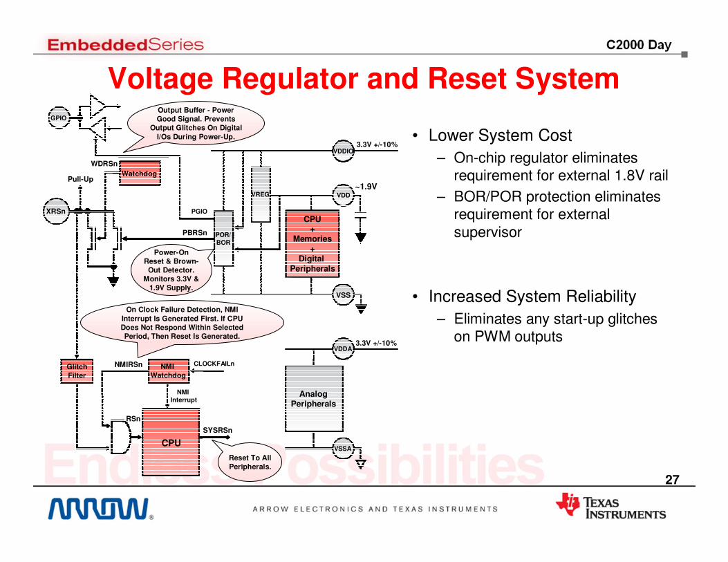
CPU+
Memories+
Digital Peripherals
Watchdog
VREG
NMI Watchdog
CLOCKFAILn
NMI Interrupt
3.3V +/-10%
~1.9V
POR/BOR
AnalogPeripherals
3.3V +/-10%
Pull-Up
XRSn
CPU
WDRSn
SYSRSn
PBRSn
GlitchFilter
RSn
VDDIO
VDD
VSS
VDDA
VSSA
GPIO
PGIO
Reset To All Peripherals.
Output Buffer - Power Good Signal. Prevents
Output Glitches On Digital
I/Os During Power-Up.
NMIRSn
On Clock Failure Detection, NMI
Interrupt Is Generated First. If CPU Does Not Respond Within Selected Period, Then Reset Is Generated.
Power-On Reset & Brown-
Out Detector. Monitors 3.3V &
1.9V Supply.
Voltage Regulator and Reset System
• Lower System Cost
– On-chip regulator eliminates requirement for external 1.8V rail
– BOR/POR protection eliminates requirement for external supervisor
• Increased System Reliability
– Eliminates any start-up glitches on PWM outputs
27

GPIO/XCLKIN
CLKIN
SYSCLK
WDCLK
Device ResetOr Interrupt
CPU
CPU Timer 2
CPU Timer 0
CPU Timer 1
Watchdog
InternalOscillator 2
10MHz
OSC2CLK
ExternalOscillator5-20MHz
X1
X2
EXTCLK CPUTMR2CLK
PLLx1x2x3
.
.x10
NMI Watchdog
CLKFAILClockFail
Detect
GPIO/XCLKOUT
/1/2/4
Internal Oscillator Accuracy~3% (85C to 125C)
Clocking System - Piccolo
InternalOscillator 1
10MHz
OSC1CLK
/1/2/4
/8/16
/1/2/4
Piccolo’s clocking system provides two zero-pin on-chip oscillators to eliminate the need for external clock circuitry. The high accuracy, high speed internal clocks are also a part of an extensive clock protection system
Lower System Cost• No external clock circuitry or crystal required
• Includes secondary internal oscillator for backup or alternate clock source
Increased System Reliability• Back-up internal oscillator automatically triggered in
case of error
• Configurable clock sources allows independent CPU, CPU Timer 2 and Watchdog clocks
• Watchdog support standards such as IEC-60730
• Automatic PWM trip in case of clock failure
• If clock failure is detected, CLKIN and WDCLK automatically switches to backup oscillator
• Two internal high-speed oscillators
• If both internal clocks fail, PLL clock automatically goes into “limp mode” to facilitate shut-down procedures. (5 MHz only)
3-tier Clock Protection
OR
28

29
Lower System Cost / Increased System Reliability
Piccolo Analog Integration
• On-Chip Voltage Regulation– On-chip regulator eliminates requirement
for external 1.8V rail
– BOR/POR protection eliminates requirement for external supervisor
– Eliminates any start-up glitches on PWM outputs
• Dual On-Chip Oscillators– No external clock circuitry required
– Independent time bases for main CPU and Watchdog support standards such as IEC-60730
• Analog Comparators– Trip PWM Outputs, Generate Interrupts,
Sync PWM Outputs, Generate ADC SOC, Route to GPIO Pins
• Analog-to-Digital Converter– Continuous sampling up to 5 MSPS– Ratio metric across full 3.3V input range– No support pins
• High Resolution PWM– High Resolution Duty Cycle Modulation
with 150ps Steps
– High Resolution Frequency Modulation with 150ps Steps
29

30
0
1
2
3
4
5
0
50
100
150
200
250
0
50
100
150
200
250
0
50
100
150
200
250
0
1
2
PiccoloTM is the right solution for Real-Time Control
General purpose(Dhrystone)Efficiency
Control algorithm(PID16)cycles
Control algorithm(PID32)cycles
Digital power(Buck loop)
cycles
Advanced control filter (FIR)
cyc/tap
Core Performance Benchmark
All benchmarks run from 0-wait RAM, using latest TI tools
Dhrystone benchmark is industry standard, does not benchmark the math performance of a processor
Operation Cortex-M3(72 MHz)
28x(60MHz)
28x+CLA(60MHz)
Feedforward control cycles 786 482 482 / 0
Feedback control cycles 1762 1081 0 / 550
Total Control Law cycles 2548 1563 482 / 550
MHz used (20 kHz loop) ~51MHz ~32MHz ~10MHz (28x) + 11MHz (CLA)
30% headroom 20% faster, lower frequency,
50% headroom
5X faster, lower frequency
80% headroom
Control Application Performance Benchmark
25% faster
30% faster
38% faster
2X faster
4X faster
= Cortex™ M3 CPU = C28x™ CPU
30

Piccolo Sample Applications
Commercial LED Lighting
• More efficient than traditional lighting, less heat dissipation
• Longer bulb life, less maintenance
• Brighter than traditional lighting
• Simpler wiring and reduced installation costs
• More reliable power production
• Better panel and system monitoring through networking
Solar Micro Inverters
Appliances
• Must meet stringent energy efficiency standards
• Safety standards being mandated such as IEC60730
• Smarter systems requiring complex algorithms and control techniques
Hybrid Electric Vehicles
• Reduces emissions and improves fuel economy
• Increased demands to improve power conversion efficiency
• Sophisticated and fast control required for battery management
31

Note: See detailed block diagram for device variations
F2833x series
• on-chip Flash only
• on-chip ADC
• 150 MHz C28x CPU
• Flexible PWM modules – Programmable period,
frequency and phase control– Dead-band generation– Programmable trip zone
allocation
• Hi-Res PWM modules with up to 65ps resolution
• 32-bit QEP modules for hardware decoding
• 32-bit capture modules
Click here for detailed block diagrams
High-performance C28x CPU
• Up to 300MHz performance
• Single cycle 32-bit MAC
• Fast interrupt response and minimal latency
Intelligent peripherals
Control-oriented architecture
• Asynchronous external memory interface
• External ADC interface
• DMA controller
Delfino Floating Point MCU MCU for Advanced Real-Time Control
C2834x series
• on-chip SRAM only
• external ADC
• 300 MHz C28x CPU
Pin-compatible Fixed-point options available for F2833x series
32
� Best mix of control peripherals� Robust software libraries� Code compatibility across C2000 platform
ranging from 40MHz to 300MHz� Increased on-chip analog integration
Serial Interfaces
Delfino Memory
0-512 KB Flash
DebugReal-time
JTAG
52-516 KB RAM
Boot ROM
Memory Interface
16/32-bit EMIF
12-bit 2-S/H 12.5 MSPSOr
External with Triggering
2x SPI
1x I2C3x SCI
3x CAN
2x McBSP
128-Bit Security Key/Lock
C28x 32-bit CPU
Up to 60 MHz32x32-bit MultiplierRMW Atomic ALU
Peripherals Timer Modules
Connectivity
88 I/Os
3x 32-bit CPU Timers
Watchdog Timer
3 x 32-bit eQEP
6 x 32-bit eCAP
FPU
Analog to Digital Converter
9x ePWM Modules:18x PWM outputs(9x 65ps high-res)
DMA• IEEE 32-bit single precision
• Eliminates scaling & saturation burden
• Magnitude calculations (division & square root)
• Park & Clark type algorithms (sin and cos)
• FFT and IIR performance improvements
32-bit floating point
32

Floating Point UnitThe FPU on Delfino devices is a logic unit that extends the C28x core to include floating-point
instructions. Supports full IEEE single-precision 754 (most widely used format).
C28x + FPU• Full floating-point or fixed-point support
• FPU instructions share same first half of pipeline as fixed-point instructions, but has its own second half
• Floating-point– Is Inherently more robust– Removes scaling & saturation burden– Reduces time-to-market
• Using floating point can reduce the cycle count for math functions by 52%. In addition, C2834x devices have reduced memory access time, resulting in 64% cycle reduction over other 28x devices.
FPU compilation and execution• Fixed-point C2000 processors use support libraries to simulate
floating-point math, store variables in stack
• Floating-point C2000 processors natively support single-precision floating point instructions, store variables in floating-point registers
• Use simple compiler switch to assemble code using FP instructions
• Separate floating-point version of IQMath, Flash API, etc.
• FPU Optimized Math Library
*State Estimator shownin 10s of cycles
Up to 64% reduction in cycles
D R E1FPU Instruction
F2F1 D1 D2
C28x + FPU Pipeline
Fetch Decode
R1 R2 E W
Read Exe Write
Documentation and Software
• TMS320C28x Floating Point Unit Instruction Set Reference Guide
• C28x FPU Primer App Note
• C28x FPU Library and C28x FPU FastRTS Library
0
20
40
60
80
100
120
140
160
Cy
cle
s
State
Estimator*
Park
Transform
PID
F28x Fixed
F28335 Float
C28346 Float
E2W
33

Floating-point Performance for Demanding Applications
*State Estimator shown in 10s of cycles
Na
no
se
co
nd
s
Up to 70% reduction in memory access time Up to 64% reduction in cycles
Up to 52% code reduction
0
2
4
6
8
10
12
F28335
(Flash)
F28335
(RAM)
C28346
150MHz
150MHz
300MHz
Access Time
Na
no
se
co
nd
s
0
10
20
30
40
50
60
70
80
90
100
Divide Sqrt Sin/Cos
Fixed Point
Floating Point
0
20
40
60
80
100
120
140
160
State
Estimator*
Park
Transform
PID
F28x Fixed
F28335 Float
C28346 Float
34
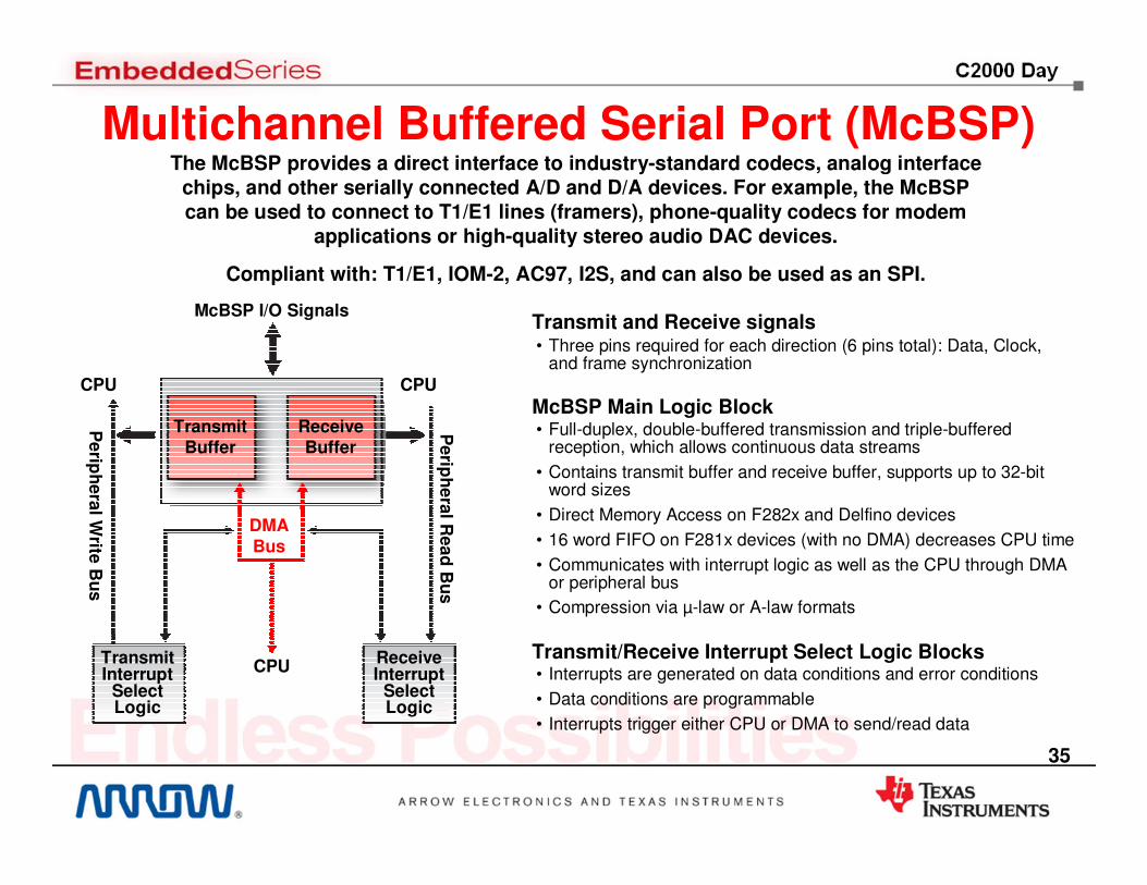
Multichannel Buffered Serial Port (McBSP)The McBSP provides a direct interface to industry-standard codecs, analog interface
chips, and other serially connected A/D and D/A devices. For example, the McBSPcan be used to connect to T1/E1 lines (framers), phone-quality codecs for modem
applications or high-quality stereo audio DAC devices.
Compliant with: T1/E1, IOM-2, AC97, I2S, and can also be used as an SPI.
McBSP I/O Signals
TransmitBuffer
ReceiveBuffer
Transmit Interrupt
Select Logic
Receive Interrupt
Select Logic
CPU CPU
Pe
riph
era
l Re
ad
Bu
s
Pe
riph
era
l Write
Bu
s
DMA Bus
CPU
McBSP Main Logic Block• Full-duplex, double-buffered transmission and triple-buffered
reception, which allows continuous data streams
• Contains transmit buffer and receive buffer, supports up to 32-bit word sizes
• Direct Memory Access on F282x and Delfino devices
• 16 word FIFO on F281x devices (with no DMA) decreases CPU time
• Communicates with interrupt logic as well as the CPU through DMAor peripheral bus
• Compression via µ-law or A-law formats
Transmit/Receive Interrupt Select Logic Blocks• Interrupts are generated on data conditions and error conditions
• Data conditions are programmable
• Interrupts trigger either CPU or DMA to send/read data
Transmit and Receive signals• Three pins required for each direction (6 pins total): Data, Clock,
and frame synchronization
35

Direct Memory Access (DMA)
Peripheral Interrupt Trigger Sources• ADC sequencers
• McBSP
• External Memory (XINTF)
• CPU Timers
• ePWM Start-of-conversion signals (F2833x/F2823x only, excl. Rev0)
• Software
Data Sources / Destinations• Some RAM zones
• External Memory zones
• ADC result registers
• McBSP transmit/receive buffers
• ePWM 1-6 registers
DMA Controller• Used to free CPU bandwidth and rearrange data for easy processing
• 6 channels with independent PIE interrupts
• Event-based machine: requires peripheral trigger to activate
• Channel 1 has the ability to be a high-priority channel
• 4 cycles/word throughput (5 for McBSP)
• Arbitration handing when CPU and DMA both try to access the sameinterface concurrently
F282x and Delfino devices contain a 6-channel DMA
CPU Timers, Software Interrupts
DMA
6 -chController
XINTFZones
SARAMZones
McBSPModule
ePWMModules*
ADCModule
DMA Bus
*F2833x/F2823x RevA and up only 36

External Interface (XINTF)
Features
• 4.008MB of address space (2.008MB for F281x devices)
• Zones can be configured individually to use a 16-bit or 32-bit data bus
• Connected to the on-chip DMA module on F283x, F282x, and C2834x devices
• Ability to extend DMA to external memory
• Programmable wait states, chip-select, and strobe timing enables glueless interface to external memories and peripherals
• XINTF clock can be disabled to save power
• Automatic read-after-write hazard protection
• Up to three stage write buffer to decrease CPU load
The external interface represents zones in the 28x memory map that are connected to external memory or peripherals. The CPU can then directly access that external resource.
CPUXINTFZones
External Memory
OrPeripheral
Memory Bus
XINTF Pins
External Interface Module Guide
F281x – SPRU067F2833x, F2823x – SPRU949C2834x – SPRUFN4
Devices Difference
F281x 16-bit bus only
F2833x, F2823x, C2834x
16 or 32-bit bus, DMA access, XINTF Clock Disable
Ext. DMA Access
37

38
Delfino Floating Point Applications
Power Delivery
Real-time analysis, conversion, or battery charging
• Line monitoring & protection
• UPS for large systems
• Battery charging
• Power line metering
Industrial Power Electronics
Smart Sensing• Radar, Laser, Doppler, Flow
Meters, Infrared Sensors
• Precision Measurements
• Gyroscopes, MEMS Sensors
• Chemical, Spectral, Electro, Photo, Reflective, Radiation Analysis
• Oscilloscopes, Medical Ultrasound and EKG
Renewable energyControls power conversion &
interface to grid or battery
• Windmill & Turbine Inverters
• Solar Inverters
• Generators
• Fuel Cells
• AC Servos, Inverters, CNC
• Motor control for industrial and aerospace
• Soft Starters, Circuit Protection
• Process Controls
• Plasma Cutters & Welders
38

CLA vs. Floating-Point Unit
Control Law Accelerator Floating-Point Unit
Independent 8 Stage Pipeline F1-D2 Shared with the C28x Pipeline
Single Cycle Math and Conversions Math and Conversions are 2 Cycle
No Data Page Pointer. Only uses Direct & Indirect with Post-Increment
Uses C28x Addressing Modes
4 Result Registers2 Independent Auxiliary RegistersNo Stack Pointer or Nested Interrupts
8 Result RegistersShares C28x Auxiliary RegistersSupports Stack, Nested Interrupts
Native Delayed Branch, Call & Return Use Delay Slots to Do Extra WorkNo repeatable instructions
Uses C28x Branch, Call and ReturnCopy flags from FPU STF to C28x ST0Repeat MACF32 & Repeat Block
Self-Contained Instruction SetData is Passed Via Message RAMs
Instructions Superset on Top of C28x Pass Data Between FPU and C28x Regs
Supports Native Integer Operations:
AND, OR, XOR, ADD/SUB, Shift
C28x Integer Operations
Programmed in Assembly Programmed in C/C++ or Assembly
Single step moves the pipe one cycle Single step flushes the pipeline
39
C2000 Product Portfolio • controlSUITE
• controlCARD Concept
• Application Developer’s Kits
• Piccolo controlSTICK
• Software Libraries & Examples
• 3rd Party Solutions & Additional Resources
40

41
controlSUITE™
Comprehensive. Intuitive. Optimized. Real world software for real-time control.
41

42
What does controlSUITE solve?
I never know if I am aware of every resource that’s availableInstall controlSUITE once and it delivers a comprehensive package of every resource available for your device or application
I like to explore a system example, then tweak to my needs vs. I like to build my application from the ground up, bit by bitcontrolSUITE offers the complete solution, with 4 levels of hardware abstraction, libraries, software examples, full systems, and GUIs you can jump in at any level depending on your experience and comfort.
My current vendor provides resources that are a) good, but expensive b) free, but aren’t properly supported c) licensed, and won’t provide sourceEverything in controlSUITE is completely free, meticulously documented, under version control, and nearly 100% open source on all software and hardware
I am never sure I am using the latest version of software, or if something completely new has been releasedcontrolSUITE can automatically or manually synchronize with a central repository, keeping you up to date with the latest revisions or newest offerings
42

43
What is controlSUITE?
CONTENT
CONTENT MANAGEMENT
+
43

44
controlSUITE Content Snapshot
Series Device Libraries Kits Infrastructure
Piccolo F2802x
Piccolo F2803x
Delfino C2834x
Delfino F2833x
Bit Fields
API
Examples
Math
DSP
Utilities
Applications
Hardware
Systems
GUI
IDE
RTOS
Real-time
Network
44

45
Software
Device: Bit Fields & APILevel 1 – Registers and AddressesBaseline assembly communication to all hardware registers and addresses
Level 4 – Framework
• State Machine / ISR Based OS
• Function-based device initialization
• Built-in task management
• Ability to connect to an external GUI
• Simple switching between RAM and Flash
Level 3 – API Drivers
• C functions that automatically set register bit fields
• Further reduces learning curve for new embedded programmers
• Common tasks and peripheral modes supported
Level 2 – Bit Fields
• Bit fields can be manipulated without masking
• Flexibility to access a register as a whole or by bits
• Advanced CCStudio™ IDE features for ease-of-useProgramming F28x Peripherals in C/C++
Hardware
Ha
rd
wa
re A
bstr
actio
n
Registers and Addresses
ADC SPI INT
CNTRL SYS PWM
GPIO TIME WDG
I2C UARTBit Fields
API Drivers
FrameworkDirect use of headers
Software
45

46
Using direct register access Using Bit Field Headers Using API Driver
Device: ExamplesEach device support package includes examples demonstrating how to utilize the bit fields or drivers to its maximum potential
• Up to 45 Bit Field examples per device
• Full example set for API Drivers
interrupt void IsrAdc( void )
{
// Period of ePWM1 is set in init;
// Multiply period by desired duty
// to get CMPA value;
EPwm1Regs.CMPA.half.CMPA =
EPwm1Regs.TBPRD * duty;
}
//Interrupts set up
elsewhere
//Set duty cycle
MOVB @9,#0x0F,UNC
//Set PWM1A on Zero Event
AND AL,@11,#0xFFFC
ORB AL,#0x02
MOV @11,AL
//Clear PWM1A on Up-count
//CompareA event
AND AL,@11,#0xFFCF
ORB AL,#0x10
MOV @11,AL
interrupt void IsrAdc( void )
{
/* set a new pwm value */
PWM_setDutyA(PWM_MODULE_2, duty );
}
Resources:Bit Field Example: Piccolo F2802x Quick Start GuideComing Soon: Piccolo F2802x API Drivers Guide 46

47
Libraries: Applications
Motor ControlPeripheral Blocks• ADC Conversion• PWM DAC
Control Blocks• 2P2Z• PID• Ramp Gen• Sine Gen• Slew Limit• CLA Versions
Topology Blocks• Buck (regular + HiRes)• PSFB (regular + HiRes)• Multi-phase Interleaved Buck• PFC 2 Phase Interleaved• PFC Current Command
PowerPeripheral Blocks• BLDC PWM• PWM Full Compare• HALL CAP• HALL GPIO• QEP• PWM DAC• Data Log
Control Blocks• PID• Speed Estimators• Speed Freq/Period• Clarke / iClarke• Park / iPark• SVGen• Commutation Trig• Impulse• Mod6 Counter• Phase Voltage Calc• Ramp Controllers• Sliding Mode Observer• ACI Flux/Speed Estimators• CLA Versions
• C or Assembly SOURCE Provided for all• Modular structures or macros with variable inputs and variable outputs• At initialization all variables are defined and outputs of one block are set as inputs to the next• At run-time the structures or macro functions are called• Complete documentation – including equations and theory – is provided for every module
Ex: Using “Park” from DMC Library
//initialization code, define macro per library#define PARK_MACRO(v)\v.Ds = _IQmpy(v.Alpha,v.Cosine) + _IQmpy(v.Beta,v.Sine);\v.Qs = _IQmpy(v.Beta,v.Cosine) - _IQmpy(v.Alpha,v.Sine);
//incremental build code, connect outputs and inputspark1.Alpha = clarke1.Alpha;park1.Beta = clarke1.Beta;
//run-time code, call the functionPARK_MACRO(park1)
Power Line Modem• plcSUITE: SFSK, OFDM, G3, PRIME
47

48
Kits: Systems of Lib Implementations
Library Blocks are “Wired” into SystemsInside a full System Framework (OS)
1. Initialization of Device2. Instance & Initialize Blocks3. Run Framework / OS4. Incremental Build Levels5. Connect & Call Blocks
Example: Sensor-less FOC Motor Control
Build Level 1: Verify Space Vector and PWMsBuild Level 2: Verify ADC conversion & Phase VoltageBuild Level 3: Tune PID for current controlBuild Level 4: Verify Sensorless estimatorBuild Level 5: Tune PID speed controlBuild Level 6: Close all loops
Build Level 5
Build Level 2
Build Level 1
Sensor-less Field Oriented Control
Permanent Magnet Synchronous Motor
48

49
Infrastructure: IDE CCStudio v4FREE with XDS100 Emulators or 32KB Version
49

50
Infrastructure: RTOS
Screenshot from DSP/BIOS v6 in Code Composer Studio, showing task priorities
BIOS is TI’s royalty/run-time free real-time operating system for processors.
Screenshot from DSP/BIOS v6 in Code Composer Studio, showing CPU load among tasks
Resources:BIOS 6.x Product Page
BIOS includes:
- Deterministic kernel with a preemptive scheduler
- Graphical or script-based configuration
- Graphical analysis & debug tools
- Interrupt dispatcher and management macros
- Multiple intertask communication services: semaphores, mailboxes, and queues
50

51
Resources:Real-Time Mode on wikiChapter 7.4 in the C28x CPU Reference Guide
Traditional debugging (Stop Mode)
• stops all threads and prevents interrupts from being handled
• makes debugging real-time systems extremely difficult
C2000 Real-time Mode:
• real-time, non-intrusive, continuous
• Does not require use of target memory, special interrupts, or SW intrusiveness
• Allows time critical interrupts to be marked for special treatment (high priority)
• Allows time-critical interrupts to be serviced while background program execution is suspended
• Included on all C2000 devices and integrated with Code Composer Studio
Infrastructure: Real-time Debug
51
52
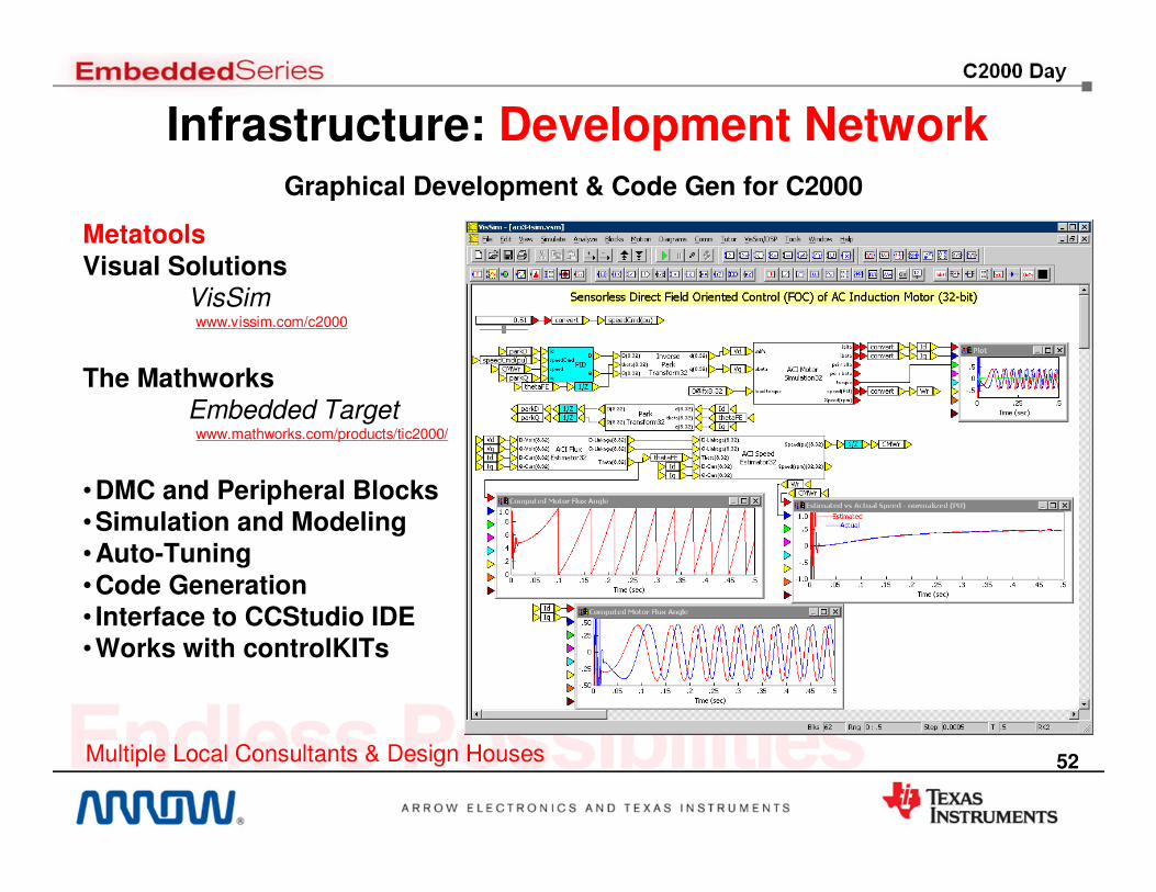
MetatoolsVisual Solutions
VisSimwww.vissim.com/c2000
The MathworksEmbedded Targetwww.mathworks.com/products/tic2000/
•DMC and Peripheral Blocks•Simulation and Modeling•Auto-Tuning•Code Generation• Interface to CCStudio IDE•Works with controlKITs
Infrastructure: Development NetworkGraphical Development & Code Gen for C2000
Multiple Local Consultants & Design Houses 52

$39 Kit includes
• Simple USB memory stick form factor evaluation tool
– Piccolo F28027
– Onboard USB JTAG emulation
– Header pins provides access to most Piccolo pins
• 11 example projects explain most Piccolo peripherals
• Fully controlSUITE compatible
• Jumpers and patch cords to easily connect pins together
• USB extension cable
• Code Composer Studio V4
• Complete hardware documentation– Gerbers, schematics, etc
controlSTICK: Low Cost Evaluation
53
54
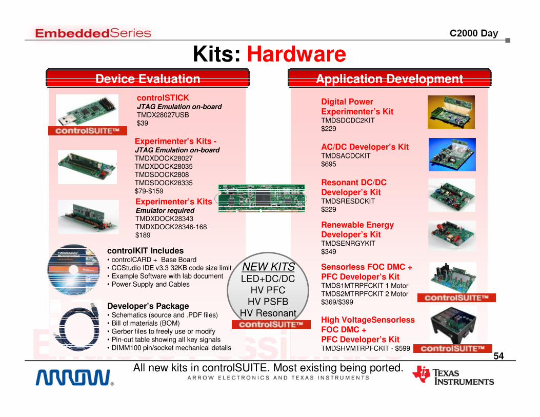
Device Evaluation Application Development
Kits: Hardware
Digital Power Experimenter’s KitTMDSDCDC2KIT$229
AC/DC Developer’s KitTMDSACDCKIT$695
Resonant DC/DC Developer’s KitTMDSRESDCKIT$229
Renewable Energy Developer’s KitTMDSENRGYKIT$349
Sensorless FOC DMC + PFC Developer’s KitTMDS1MTRPFCKIT 1 MotorTMDS2MTRPFCKIT 2 Motor$369/$399
Experimenter’s Kits -JTAG Emulation on-boardTMDXDOCK28027TMDXDOCK28035TMDSDOCK2808TMDSDOCK28335$79-$159
Experimenter’s KitsEmulator requiredTMDXDOCK28343TMDXDOCK28346-168$189
Developer’s Package• Schematics (source and .PDF files)• Bill of materials (BOM)• Gerber files to freely use or modify• Pin-out table showing all key signals • DIMM100 pin/socket mechanical details
controlKIT Includes• controlCARD + Base Board• CCStudio IDE v3.3 32KB code size limit• Example Software with lab document• Power Supply and Cables
High VoltageSensorlessFOC DMC + PFC Developer’s KitTMDSHVMTRPFCKIT - $599
controlSTICKJTAG Emulation on-boardTMDX28027USB $39
All new kits in controlSUITE. Most existing being ported.
NEW KITSLED+DC/DC
HV PFCHV PSFB
HV Resonant
54

55
Kits: HardwareHardware Developer’s Package
Hardware Developer’s Package includes:• Bill of Materials
• PCB layout
• Schematics
• Gerbers
We provide you with all the necessary files to recreate the hardware. The PCB layout and schematics are broken up into modules that can be interconnected or implanted into a new design.
controlCARDs and controlKITs
55

56
Kits: GUIs
• Connects through USB – Serial built in to each kit
• CCStudio (IDE) not required
• Images pre-loaded into flash on-chip for immediate use out of box
• Source code for GUIs provided – Roll your own!
High Voltage Motor Control GUILED Panel Board GUI
56

C2000 Community ResourcesWorkshops & Trainings
• Digital Power Multi-Day Workshop
• Piccolo One-Day Workshop
• 28x Multi-Day Workshop
• Online Training & Videos
• And More…
More Information
Engineering Services
• Design Services
• System Integration/Reference Designs
• Software Libraries
• Gang Programming
More Information
3rd Party Tools
• JTAG Emulators and Adaptors
• Flash Programming
• Development and Evaluation Boards
• Simulators and Code Generation
More Information
Academic
• Teaching ROM
• Lab Documents
• Code Examples
• Development Boards
More Information
57

The Solution for Real-Time Control
Roadmap• 40 MHz Piccolo to 300MHz Delfino controllers
• Starting sub $2
• Embedded Flash, Embedded SRAM, small packages to large I/O
• Floating point or fixed point core
• Future derivatives providing higher performance, additional connectivity, smaller packages, and safety enhancements
C2000
• Dual on-chip high precision oscillators• On-chip voltage regulation• Analog comparator with DAC reference• Enhanced PWM, CAP, QEP• Up to 512kB on-chip Flash• Up to 516KB on-chip SRAM• I2C, SPI, UART/LIN, CAN, Buffered
Serial Port• and more…
IntegrationPerformance• 40-300MHz Control Savvy 32-bit 28x CPU
• Control Law Accelerator for high speed control loops
• Floating Point Unit
• Most efficient control techniques
• Hi-res PWM with 150ps resolution
• Up to 12.5 MSPS 12-bit ADC
Ease of Use• Low cost, modular dev tools
• Open source developers package
• Flexible software libraries and framework
• Best in class compiler efficiency
• Robust header files and software examples
• Unified memory architecture
• 16 and 32-bit instructions
58

Demos• controlSUITE
• Dual Motor Control and PFC Developer’s Kit
59

60
controlSUITE Desktop
• Launch CCSv4 example projects
• View documentation and online resources
• Access libraries and utilities
• View datasheets and user guides
• See our most useful and popular application notes
• Find all training from live hands-on training to on-demand classes to videos and E2E forum support
Easy navigation to all controlSUITE software, as well as C2000 resources
Download from www.ti.com/controlSUITE 60

Low Voltage Dual Axis FOC Motor Control + PFC Kit
• Piccolo F28035 controlCARD
• Sensorless Sinusoidal SVPWM based Field Oriented Control
• Single or Dual Axis Operation
• Integrated Digital Power Factor Correction
• Hardware Features– 100W 2 phase interleaved power factor
correction stage– 2 x 60 W motor driver stages based on
TI DRV8402 motor driver chips– On board isolated XDS100 JTAG
emulation
• Software Lab Projects– Standalone PFC– Dual Axis– Single Axis + PFC– Dual Axis + PFC (coming soon)
$399 Motor Control and PFC Kit Includes
TMDS2MTRPFCKIT(2 motors)TMDS1MTRPFCKIT(1 motor)
No external emulator required!
61

Motor Control GUI
62

C2000 Day
Visit the TI eStore at http://www.ti-estore.com/ and take advantage of these limited time discounts!
50% off Piccolo controlSTICK–Regular price: $39. Discount Price: $19–Part number: TMDX28027USB –Discount code: C2000Day1
25% off C2000 tools below:
•Piccolo F28027 Experimenter’s Kit–Regular price: $79. C2000 Day Price:$59 –Part number: TMDXDOCK28027 –Code: C2000Day2
•Piccolo F28035 Experimenter’s Kit –Regular price:$89. C2000 Day Price: $66–Part number: TMDXDOCK28035–Code: C2000Day3
•F28335 Experimenter Kit –Regular price: $99. C2000 Day Price: $75–Part number: TMDSDOCK28335–Code: C2000Day4
Discount Terms: –Each customer can order up to one of each of the 7 tools. –You can enter multiple discount codes in one order. –Codes are valid through December 15, 2010. –You do need to have a my.TI account to place an order, however, if you do not have one signing up will only require you to enter a user name and password. This will allow you to review, track and reorder at a later date–If you do not want to enter a user name and password, you call also call the Product Info Center and order the tools with your discount codes at (972) 644-5580–For questions or help please email [email protected]
•DC/DC LED Lighting Kit–Regular price:$379. C2000 Day Price: $284–Part number: TMDSDCDCLEDKIT –Code: C2000Day5
•Dual Motor Control and PFC Developer’s Kit –Regular price: $ C2000 Day Price: $299–Part number: TMDS2MTRPFCKIT–Code: C2000Day6
•High Voltage PFC and Motor Control Developer’s Kit –Regular price: $599. C2000 Day Price: $449–Part number: TMDSHVMTRPFCKIT–Code: C2000Day7
Exclusive C2000 Day Discounts
63

Welcome to MCU Day – One Day, Multiple Solutions64
Thank you!
64

Solutions
Coming Soon
� DRV83x2 + Piccolo Kit for BLDC/PMSM
� DRV84x2 + Piccolo Kit for Stepper/Brushed
� PFC using new DPSLib (28x and CLA)
� FOC on CLA
MethodologiesC2000: Motor Control
Motor Control 1-day WorkshopOn-Line Self-Paced Coming 2H10
Low Voltage Dual AxisDMC + PFC KitTMDS1MTRPFCKITTMDS2MTRPFCKIT$369/$399
High VoltageDMC + PFC KitTMDSHVMTRPFCKIT$599
Quick StartGUI with all projects Flashedin MCU
Matlab & VisSim IntegrationSimulation, Modeling, Loop Optimization, Graphical Development, Peripheral Abstraction, Auto Code Gen, Works with TI Hardware
Incremental Build Based Projects
- Incremental section of code built each level- Verify each portion of their system
-PWMs, feedback, calculations-Control laws, inner/outer loop, supervision
- Critical in motor control with so manydifferent system variables
High energy efficiency via Advanced Control
– Variable speed Real-time control
– Better dynamic and transient control
Broadest MCU Architecture
– 40-300MHz Fixed & Floating Point
– Parallel FP CLA for fastest loops
– Single Cycle 32x32-bit MAC
– Fast interrupts
– Flexible & Fast interrupt system
– Real-time debugging
– Best in class ADC performance
Piccolo Family for Lowest System Cost
– High Level of Integration
– Integrated Dual OSC, VREG, Watchdogs
– Limited life support
– No external GPIO filters needed
www.ti.com/c2000dmc65

Digital Power Experimenter KitTMDSDCDC2KIT$229
AC/DC Developer KitTMDSACDCKIT$695
Resonant DC/DC Developer’s KitTMDSRESDCKIT$229
Solutions
Coming in 2010
� New DPSLib in controlSUITE™
� High Voltage PFC Kit
� AC/DC Kit port to Piccolo & controlSUITE™
� High Voltage PSFB Kit
� High Voltage Resonant LLC Kit
� Control Loop Tuning Wizard
Methodologies
C2000: Digital Power
Digital Power 3-day Workshopsponsored by Biricha Digital Power Ltd
Digital Power 1-day WorkshopOn-Line Self-Paced Coming Soon!
Reduces costs
-Tunable platforms
-Calibration across operating range
-Reduced board area and parts count
Higher quality
-Adaptive; efficiency across load range
-Flexibility through programmability
-Calibration at final functional test
-Less drift and better noise immunity
-Monitoring for quality improvement
-Proven concept in digital motor control
Higher reliability
-Built-in supervision
-Diagnostics, failure prediction
www.ti.com/c2000getstarted66