Embed Size (px)
Citation preview

8/6/2019 C11 Control Devices
http://slidepdf.com/reader/full/c11-control-devices 1/60
Chapter 11 ² Control DevicesChapter 11 ² Control Devices
Kaw AreaKaw AreaTechnical SchoolTechnical School
Industrial TechnologyIndustrial Technology
8/6/2019 C11 Control Devices
http://slidepdf.com/reader/full/c11-control-devices 2/60
Chapter 11 ² Control DevicesChapter 11 ² Control Devices
Kaw AreaKaw AreaTechnical SchoolTechnical School
Richard E. StephensCET Sr.
Richard E. StephensCET Sr.
Electrical ControlElectrical Control
Systems ISystems I
8/6/2019 C11 Control Devices
http://slidepdf.com/reader/full/c11-control-devices 3/60
P ower P oint ® P resentation P ower P oint ® P resentation
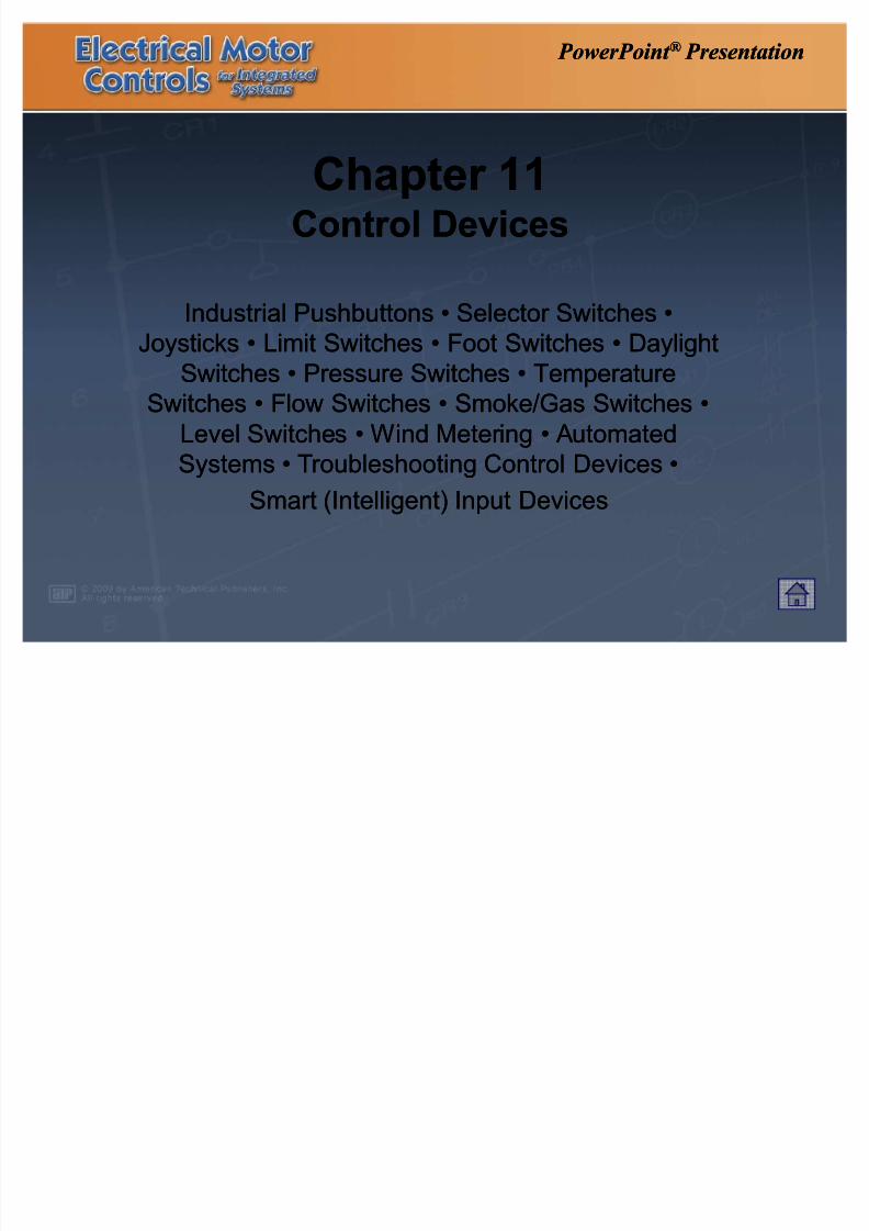
Chapter 11Chapter 11Control DevicesControl Devices
Industrial Pushbuttons � Selector Switches �
Joysticks � Limit Switches � Foot Switches � Daylight
Switches � Pressure Switches � Temperature
Switches � Flow Switches � Smoke/Gas Switches �
Level Switches � Wind Metering � Automated
Systems � Troubleshooting Control Devices �
Smart (Intelligent) Input Devices
8/6/2019 C11 Control Devices
http://slidepdf.com/reader/full/c11-control-devices 4/60
Chapter 11 ² Control DevicesChapter 11 ² Control Devices
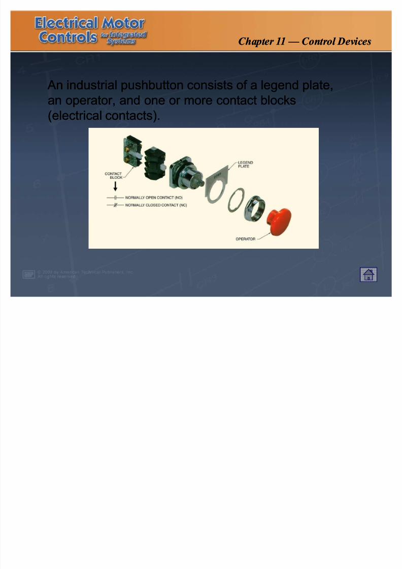
An industrial pushbutton consists of a legend plate,
an operator, and one or more contact blocks
(electrical contacts).
An industrial pushbutton consists of a legend plate,
an operator, and one or more contact blocks
(electrical contacts).
8/6/2019 C11 Control Devices
http://slidepdf.com/reader/full/c11-control-devices 5/60
Chapter 11 ² Control DevicesChapter 11 ² Control Devices
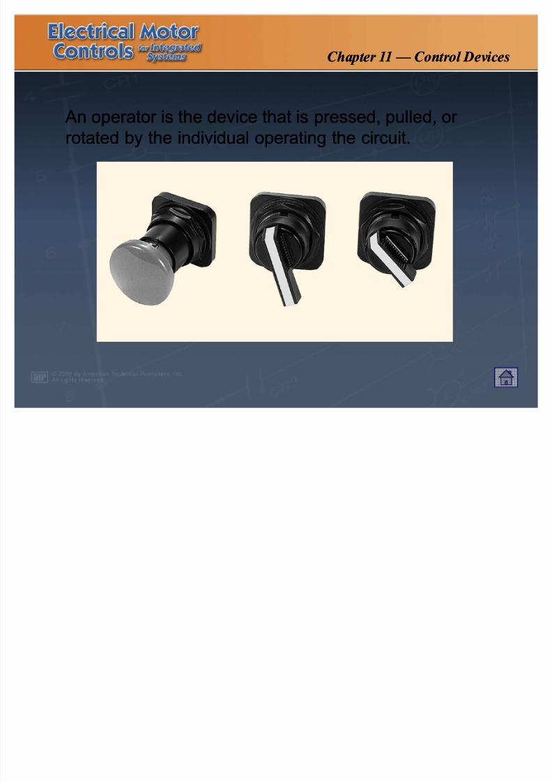
An operator is the device that is pressed, pulled, or
rotated by the individual operating the circuit.
An operator is the device that is pressed, pulled, or
rotated by the individual operating the circuit.
8/6/2019 C11 Control Devices
http://slidepdf.com/reader/full/c11-control-devices 6/60
Chapter 11 ² Control DevicesChapter 11 ² Control Devices
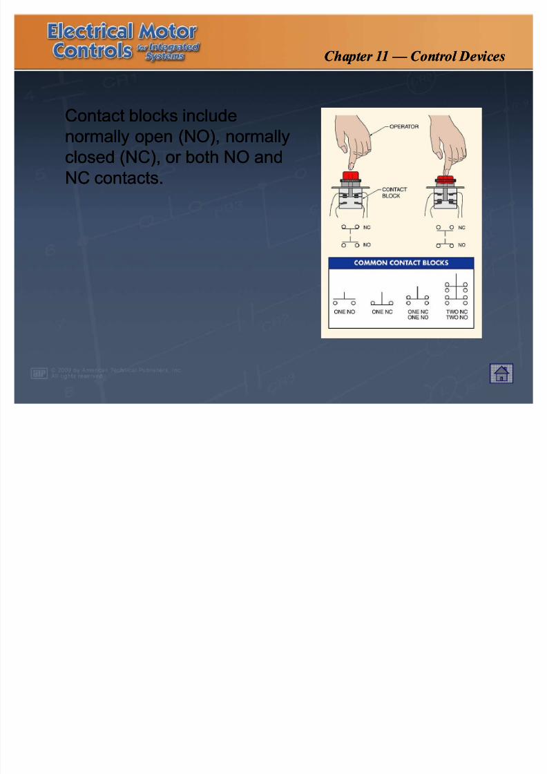
Contact blocks include
normally open (NO), normally
closed (NC), or both NO and
NC contacts.
Contact blocks include
normally open (NO), normally
closed (NC), or both NO and
NC contacts.
8/6/2019 C11 Control Devices
http://slidepdf.com/reader/full/c11-control-devices 7/60
Chapter 11 ² Control DevicesChapter 11 ² Control Devices
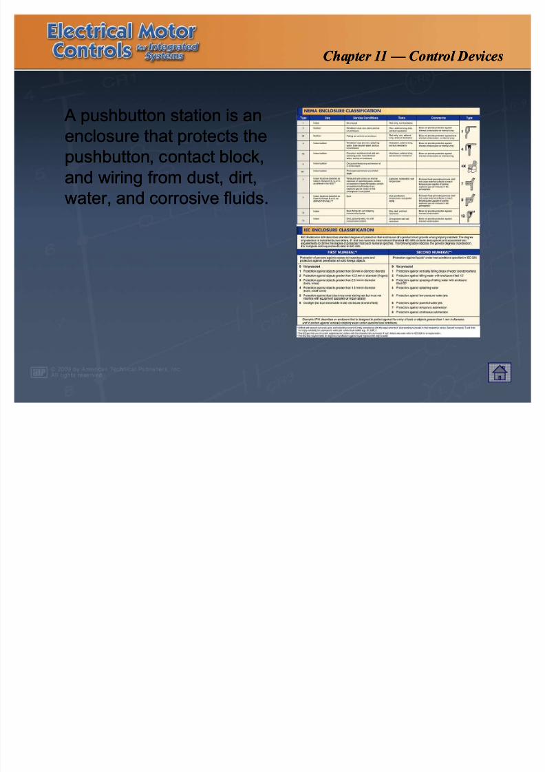
A pushbutton station is an
enclosure that protects the
pushbutton, contact block,
and wiring from dust, dirt,
water, and corrosive fluids.
A pushbutton station is an
enclosure that protects the
pushbutton, contact block,
and wiring from dust, dirt,
water, and corrosive fluids.

8/6/2019 C11 Control Devices
http://slidepdf.com/reader/full/c11-control-devices 8/60
Chapter 11 ² Control DevicesChapter 11 ² Control Devices
A two-position selector switch allows the operator to
select one of two circuit conditions.
A two-position selector switch allows the operator to
select one of two circuit conditions.
8/6/2019 C11 Control Devices
http://slidepdf.com/reader/full/c11-control-devices 9/60
Chapter 11 ² Control DevicesChapter 11 ² Control Devices
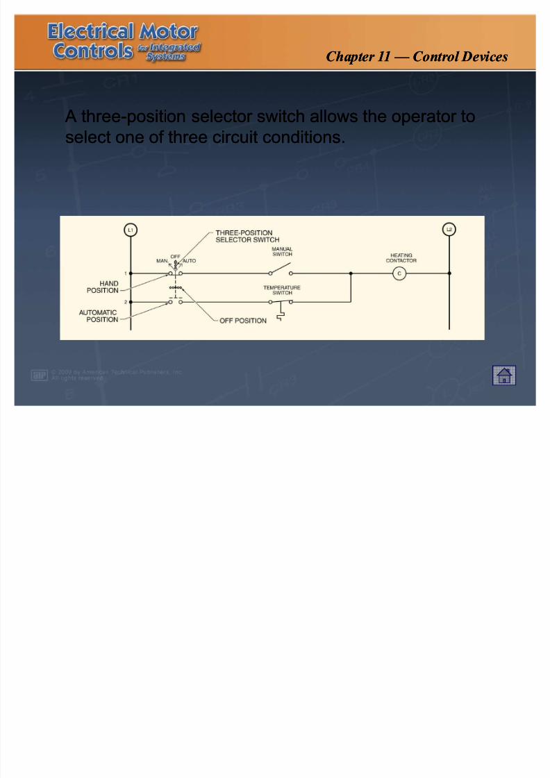
A three-position selector switch allows the operator to
select one of three circuit conditions.
A three-position selector switch allows the operator to
select one of three circuit conditions.
8/6/2019 C11 Control Devices
http://slidepdf.com/reader/full/c11-control-devices 10/60
Chapter 11 ² Control DevicesChapter 11 ² Control Devices
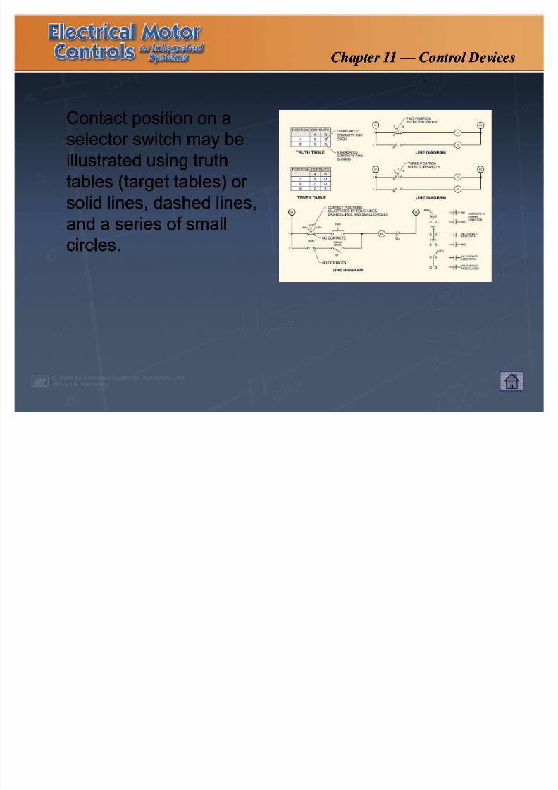
Contact position on a
selector switch may be
illustrated using truth
tables (target tables) or
solid lines, dashed lines,
and a series of small
circles.
Contact position on a
selector switch may be
illustrated using truth
tables (target tables) or
solid lines, dashed lines,
and a series of small
circles.

8/6/2019 C11 Control Devices
http://slidepdf.com/reader/full/c11-control-devices 11/60
Chapter 11 ² Control DevicesChapter 11 ² Control Devices
A joystick is used to
control many different
circuit operations from
one location.
A joystick is used to
control many different
circuit operations from
one location.

8/6/2019 C11 Control Devices
http://slidepdf.com/reader/full/c11-control-devices 12/60
Chapter 11 ² Control DevicesChapter 11 ² Control Devices
Limit switches are used
to convert a mechanical
motion into an electrical
signal.
Limit switches are used
to convert a mechanical
motion into an electrical
signal.
8/6/2019 C11 Control Devices
http://slidepdf.com/reader/full/c11-control-devices 13/60
Chapter 11 ² Control DevicesChapter 11 ² Control Devices
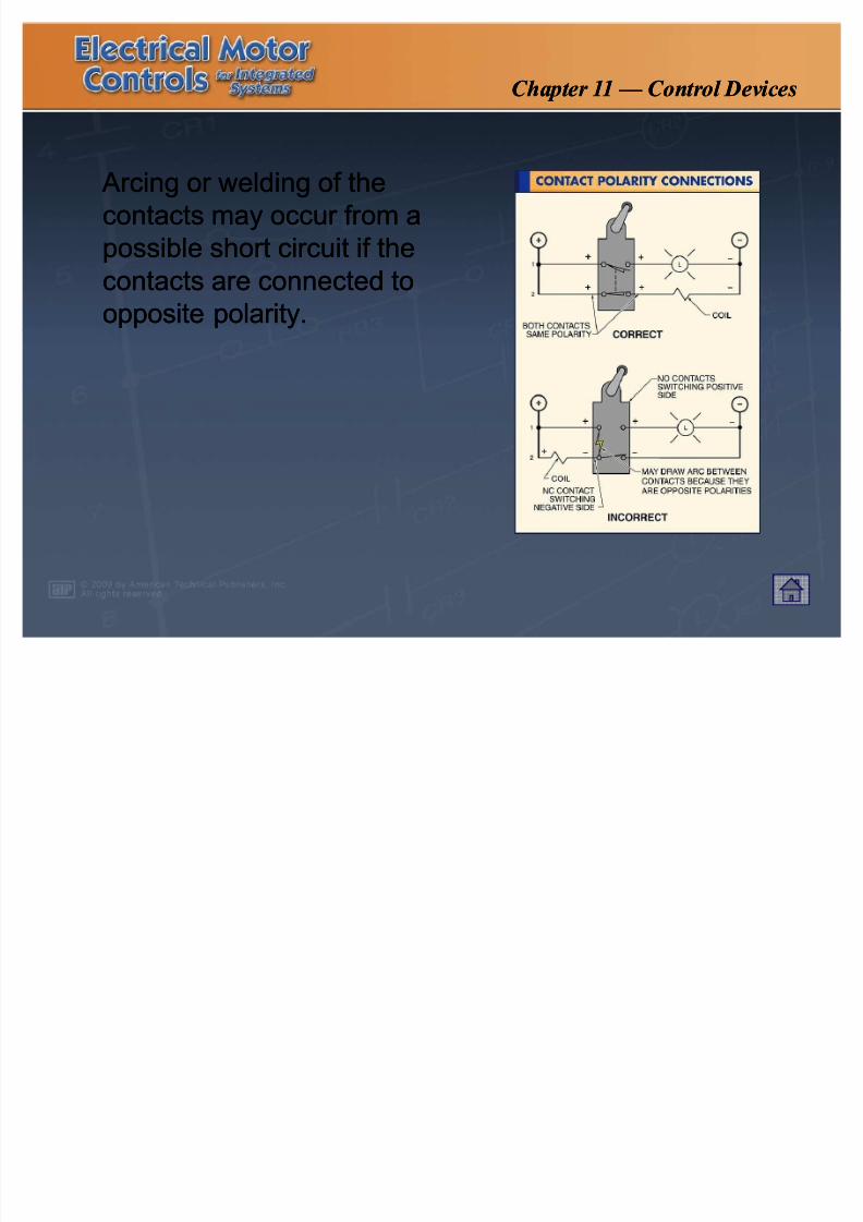
Arcing or welding of the
contacts may occur from a
possible short circuit if the
contacts are connected to
opposite polarity.
Arcing or welding of the
contacts may occur from a
possible short circuit if the
contacts are connected to
opposite polarity.
8/6/2019 C11 Control Devices
http://slidepdf.com/reader/full/c11-control-devices 14/60
Chapter 11 ² Control DevicesChapter 11 ² Control Devices
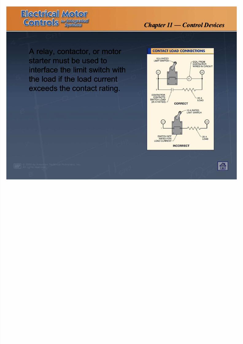
A relay, contactor, or motor
starter must be used to
interface the limit switch with
the load if the load current
exceeds the contact rating.
A relay, contactor, or motor
starter must be used to
interface the limit switch with
the load if the load current
exceeds the contact rating.
8/6/2019 C11 Control Devices
http://slidepdf.com/reader/full/c11-control-devices 15/60
Chapter 11 ² Control DevicesChapter 11 ² Control Devices
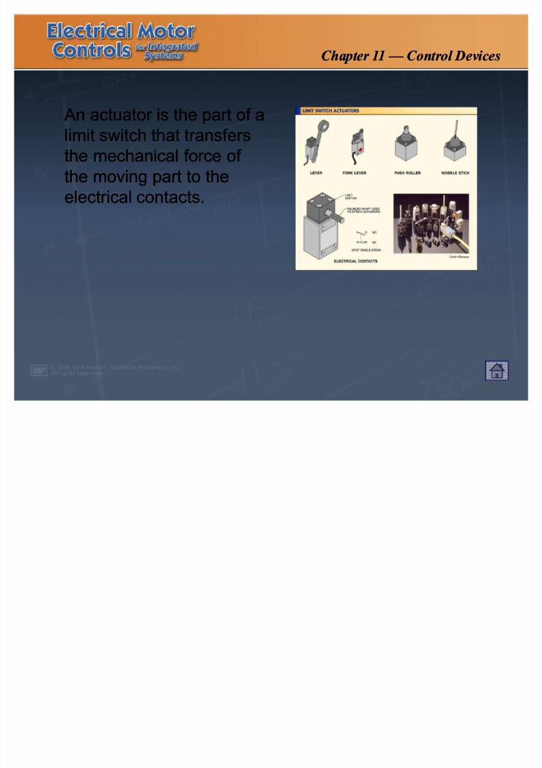
An actuator is the part of a
limit switch that transfers
the mechanical force of
the moving part to the
electrical contacts.
An actuator is the part of a
limit switch that transfers
the mechanical force of
the moving part to the
electrical contacts.

8/6/2019 C11 Control Devices
http://slidepdf.com/reader/full/c11-control-devices 16/60
Chapter 11 ² Control DevicesChapter 11 ² Control Devices
Limit switches should not
be operated beyond the
manufacturer¶s
recommended travel
specifications.
Limit switches should not
be operated beyond the
manufacturer¶s
recommended travel
specifications.
8/6/2019 C11 Control Devices
http://slidepdf.com/reader/full/c11-control-devices 17/60
Chapter 11 ² Control DevicesChapter 11 ² Control Devices
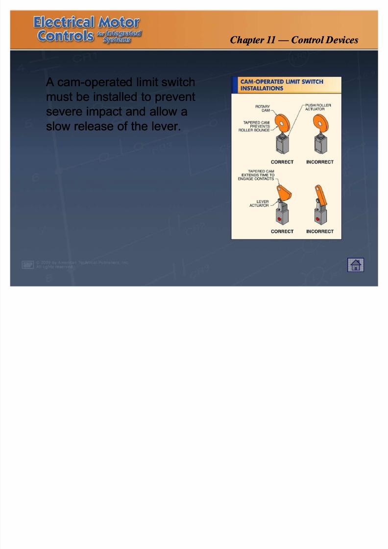
A cam-operated limit switch
must be installed to prevent
severe impact and allow a
slow release of the lever.
A cam-operated limit switch
must be installed to prevent
severe impact and allow a
slow release of the lever.
8/6/2019 C11 Control Devices
http://slidepdf.com/reader/full/c11-control-devices 18/60
Chapter 11 ² Control DevicesChapter 11 ² Control Devices
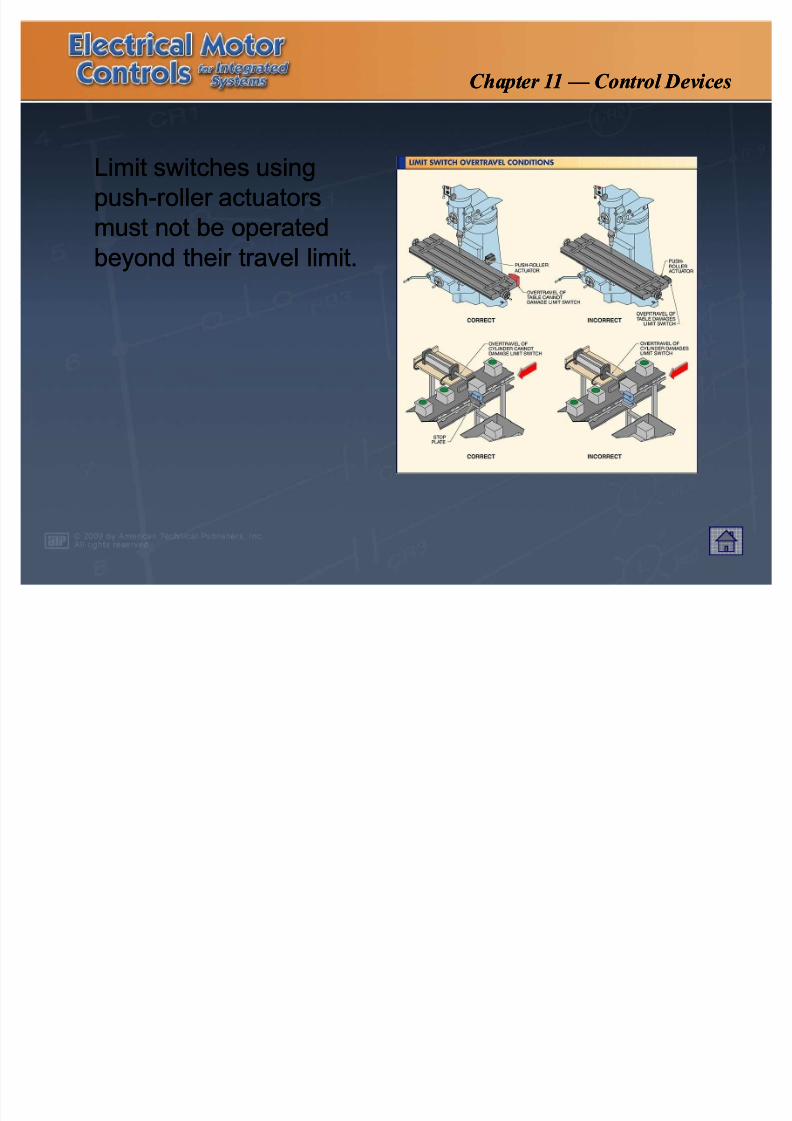
Limit switches using
push-roller actuators
must not be operated
beyond their travel limit.
Limit switches using
push-roller actuators
must not be operated
beyond their travel limit.
8/6/2019 C11 Control Devices
http://slidepdf.com/reader/full/c11-control-devices 19/60
Chapter 11 ² Control DevicesChapter 11 ² Control Devices
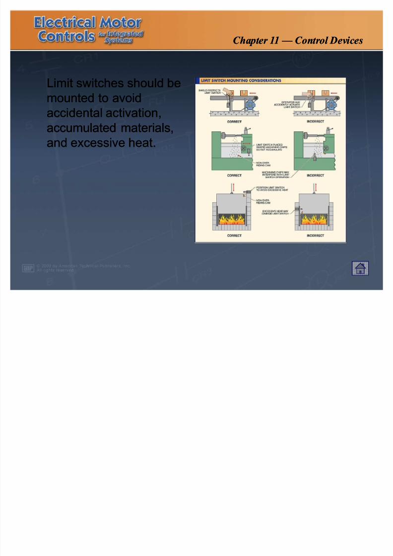
Limit switches should be
mounted to avoid
accidental activation,
accumulated materials,
and excessive heat.
Limit switches should be
mounted to avoid
accidental activation,
accumulated materials,
and excessive heat.
8/6/2019 C11 Control Devices
http://slidepdf.com/reader/full/c11-control-devices 20/60
Chapter 11 ² Control DevicesChapter 11 ² Control Devices
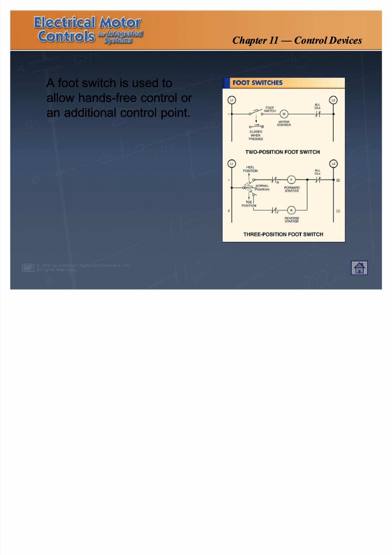
A foot switch is used to
allow hands-free control or
an additional control point.
A foot switch is used to
allow hands-free control or
an additional control point.
8/6/2019 C11 Control Devices
http://slidepdf.com/reader/full/c11-control-devices 21/60
Chapter 11 ² Control DevicesChapter 11 ² Control Devices
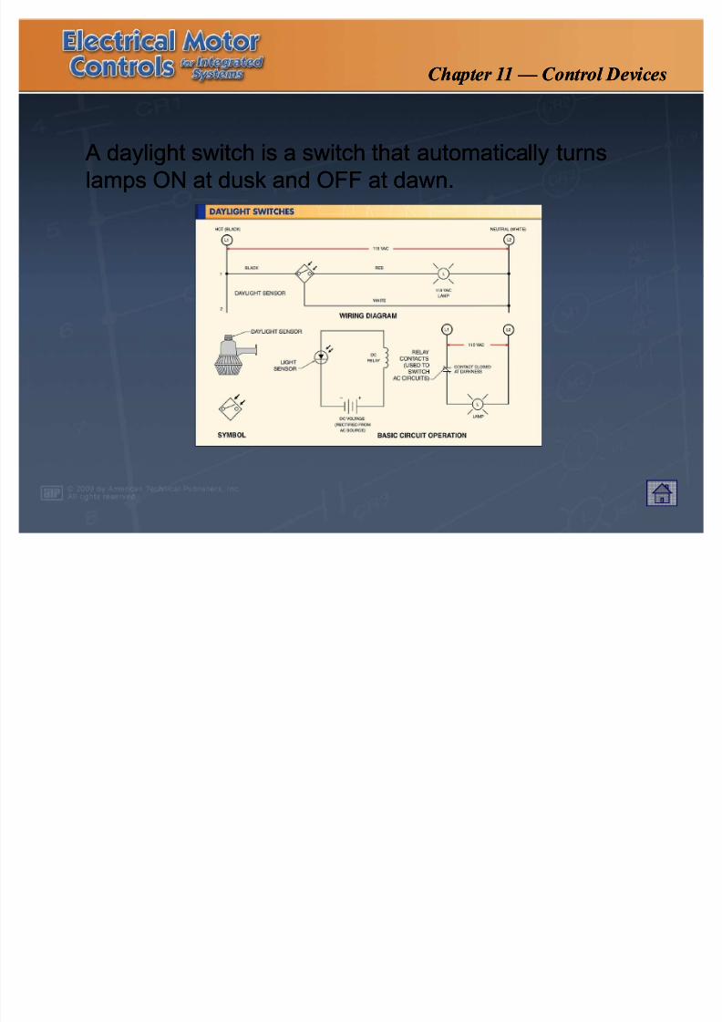
A daylight switch is a switch that automatically turns
lamps ON at dusk and OFF at dawn.
A daylight switch is a switch that automatically turns
lamps ON at dusk and OFF at dawn.
8/6/2019 C11 Control Devices
http://slidepdf.com/reader/full/c11-control-devices 22/60
Chapter 11 ² Control DevicesChapter 11 ² Control Devices
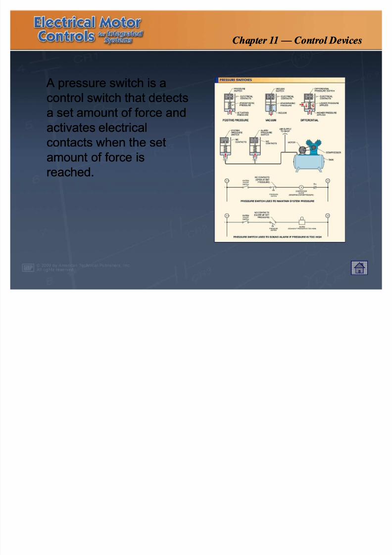
A pressure switch is a
control switch that detects
a set amount of force and
activates electrical
contacts when the setamount of force is
reached.
A pressure switch is a
control switch that detects
a set amount of force and
activates electrical
contacts when the setamount of force is
reached.
8/6/2019 C11 Control Devices
http://slidepdf.com/reader/full/c11-control-devices 23/60
8/6/2019 C11 Control Devices
http://slidepdf.com/reader/full/c11-control-devices 24/60
Chapter 11 ² Control DevicesChapter 11 ² Control Devices
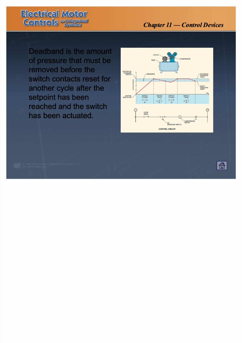
Deadband is the amount
of pressure that must be
removed before the
switch contacts reset for
another cycle after thesetpoint has been
reached and the switch
has been actuated.
Deadband is the amount
of pressure that must be
removed before the
switch contacts reset for
another cycle after thesetpoint has been
reached and the switch
has been actuated.
8/6/2019 C11 Control Devices
http://slidepdf.com/reader/full/c11-control-devices 25/60
Chapter 11 ² Control DevicesChapter 11 ² Control Devices
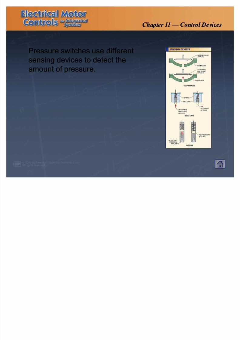
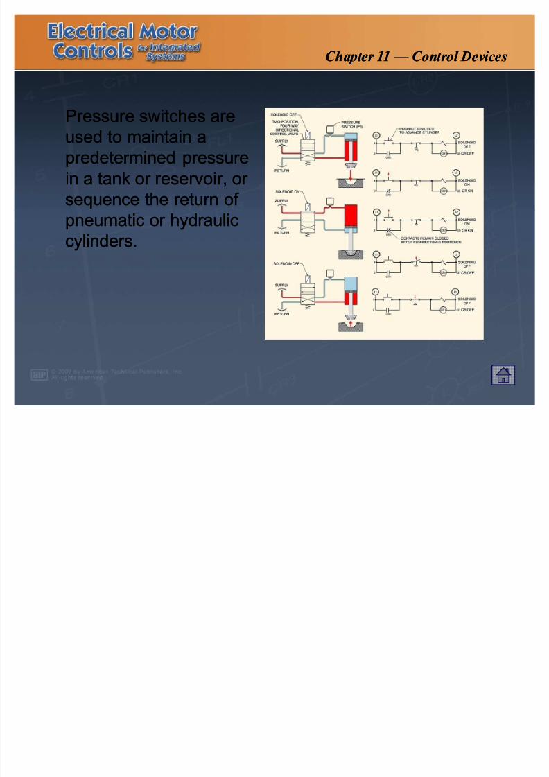
Pressure switches are
used to maintain a
predetermined pressure
in a tank or reservoir, or
sequence the return of pneumatic or hydraulic
cylinders.
Pressure switches are
used to maintain a
predetermined pressure
in a tank or reservoir, or
sequence the return of pneumatic or hydraulic
cylinders.
8/6/2019 C11 Control Devices
http://slidepdf.com/reader/full/c11-control-devices 26/60
Chapter 11 ² Control DevicesChapter 11 ² Control Devices
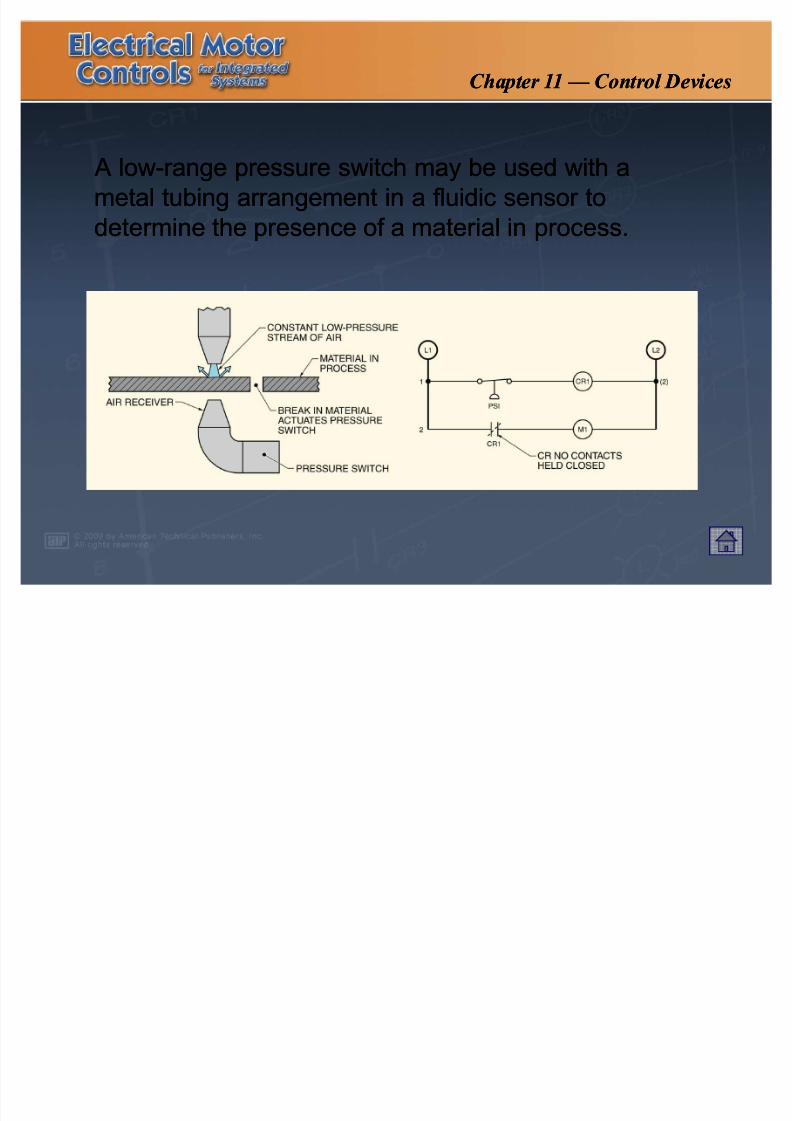
A low-range pressure switch may be used with a
metal tubing arrangement in a fluidic sensor to
determine the presence of a material in process.
A low-range pressure switch may be used with a
metal tubing arrangement in a fluidic sensor to
determine the presence of a material in process.
8/6/2019 C11 Control Devices
http://slidepdf.com/reader/full/c11-control-devices 27/60
Chapter 11 ² Control DevicesChapter 11 ² Control Devices
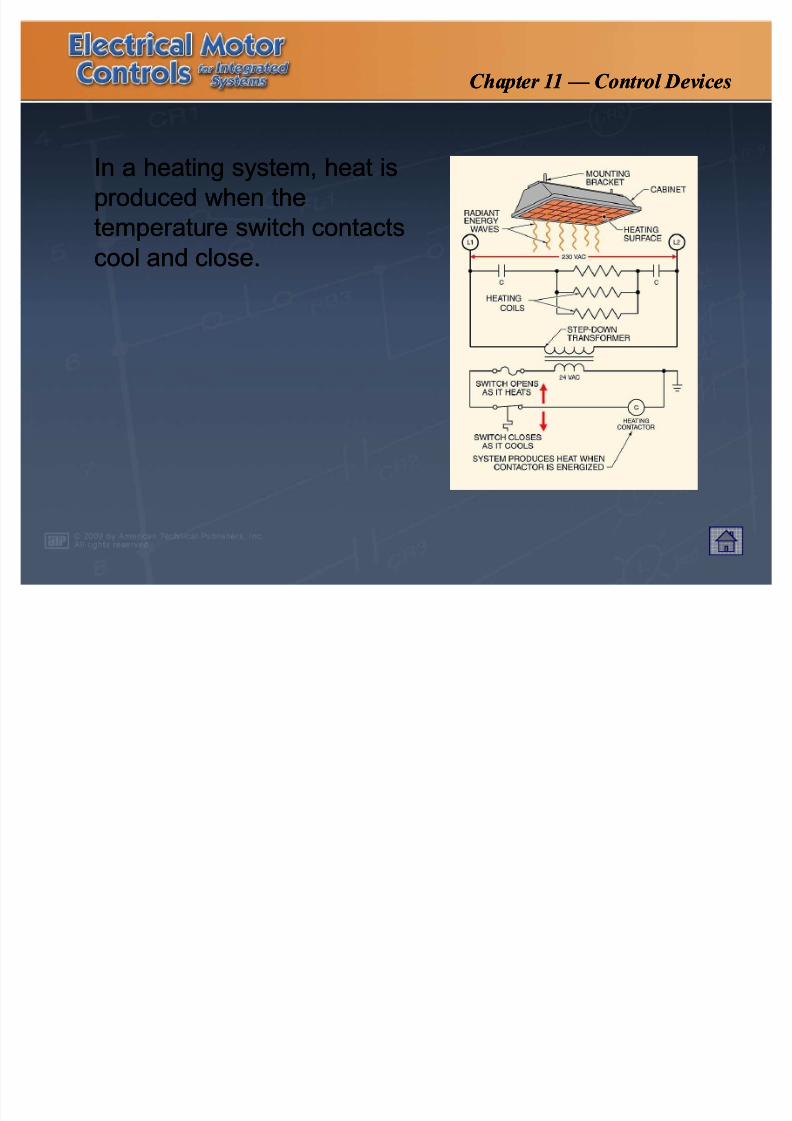
In a heating system, heat is
produced when the
temperature switch contacts
cool and close.
In a heating system, heat is
produced when the
temperature switch contacts
cool and close.
8/6/2019 C11 Control Devices
http://slidepdf.com/reader/full/c11-control-devices 28/60
Chapter 11 ² Control DevicesChapter 11 ² Control Devices
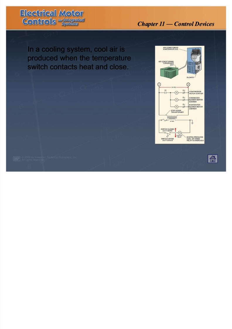
In a cooling system, cool air is
produced when the temperature
switch contacts heat and close.
In a cooling system, cool air is
produced when the temperature
switch contacts heat and close.
8/6/2019 C11 Control Devices
http://slidepdf.com/reader/full/c11-control-devices 29/60
Chapter 11 ² Control DevicesChapter 11 ² Control Devices
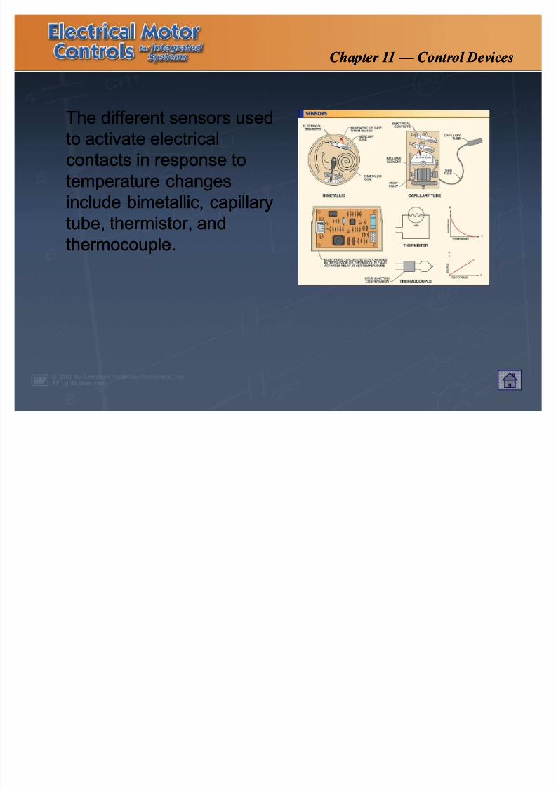
The different sensors used
to activate electrical
contacts in response to
temperature changes
include bimetallic, capillarytube, thermistor, and
thermocouple.
The different sensors used
to activate electrical
contacts in response to
temperature changes
include bimetallic, capillarytube, thermistor, and
thermocouple.
8/6/2019 C11 Control Devices
http://slidepdf.com/reader/full/c11-control-devices 30/60
Chapter 11 ² Control DevicesChapter 11 ² Control Devices
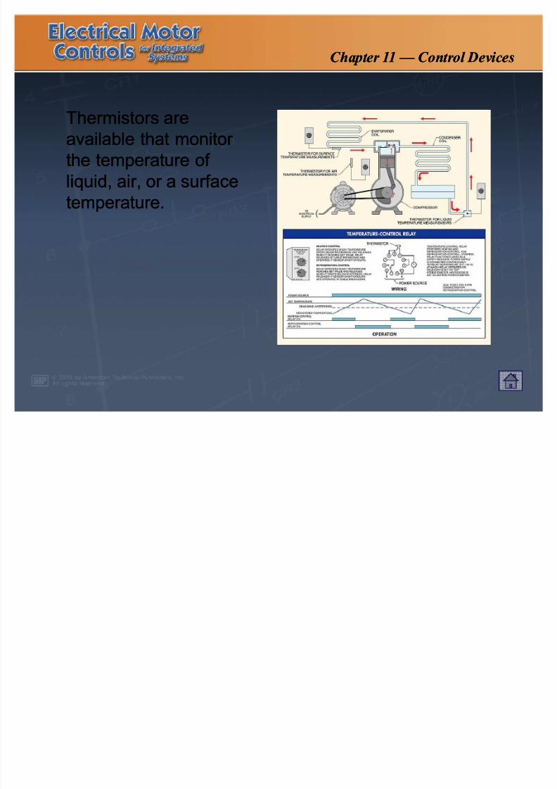
Thermistors are
available that monitor
the temperature of
liquid, air, or a surface
temperature.
Thermistors are
available that monitor
the temperature of
liquid, air, or a surface
temperature.

8/6/2019 C11 Control Devices
http://slidepdf.com/reader/full/c11-control-devices 31/60
Chapter 11 ² Control DevicesChapter 11 ² Control Devices
A flow switch is a control switch that detects the
movement of a fluid.
A flow switch is a control switch that detects the
movement of a fluid.
8/6/2019 C11 Control Devices
http://slidepdf.com/reader/full/c11-control-devices 32/60
Chapter 11 ² Control DevicesChapter 11 ² Control Devices
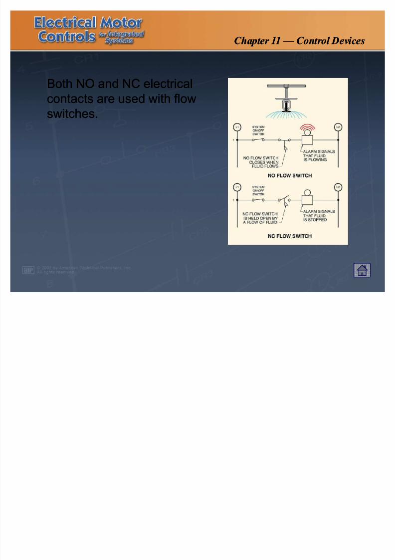
Both NO and NC electrical
contacts are used with flow
switches.
Both NO and NC electrical
contacts are used with flow
switches.
8/6/2019 C11 Control Devices
http://slidepdf.com/reader/full/c11-control-devices 33/60
Chapter 11 ² Control DevicesChapter 11 ² Control Devices
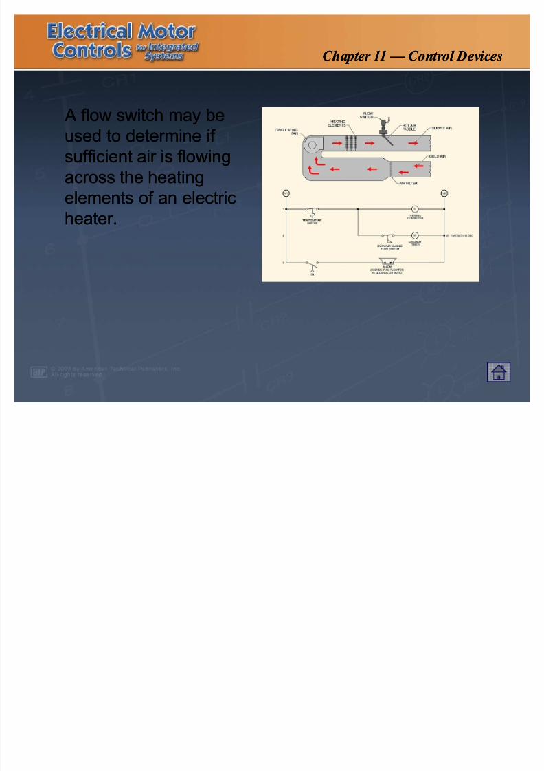
A flow switch may be
used to determine if
sufficient air is flowing
across the heating
elements of an electricheater.
A flow switch may be
used to determine if
sufficient air is flowing
across the heating
elements of an electricheater.
8/6/2019 C11 Control Devices
http://slidepdf.com/reader/full/c11-control-devices 34/60
Chapter 11 ² Control DevicesChapter 11 ² Control Devices
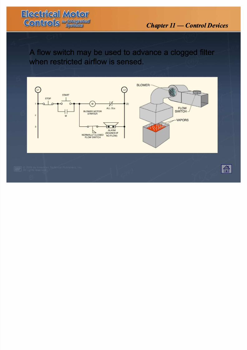
A flow switch may be used to advance a clogged filter
when restricted airflow is sensed.
A flow switch may be used to advance a clogged filter
when restricted airflow is sensed.
8/6/2019 C11 Control Devices
http://slidepdf.com/reader/full/c11-control-devices 35/60
Chapter 11 ² Control DevicesChapter 11 ² Control Devices
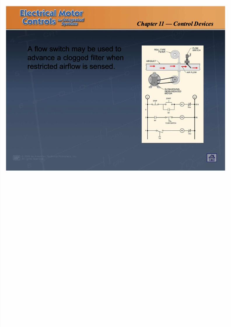
A flow switch may be used to
advance a clogged filter when
restricted airflow is sensed.
A flow switch may be used to
advance a clogged filter when
restricted airflow is sensed.
8/6/2019 C11 Control Devices
http://slidepdf.com/reader/full/c11-control-devices 36/60
Chapter 11 ² Control DevicesChapter 11 ² Control Devices
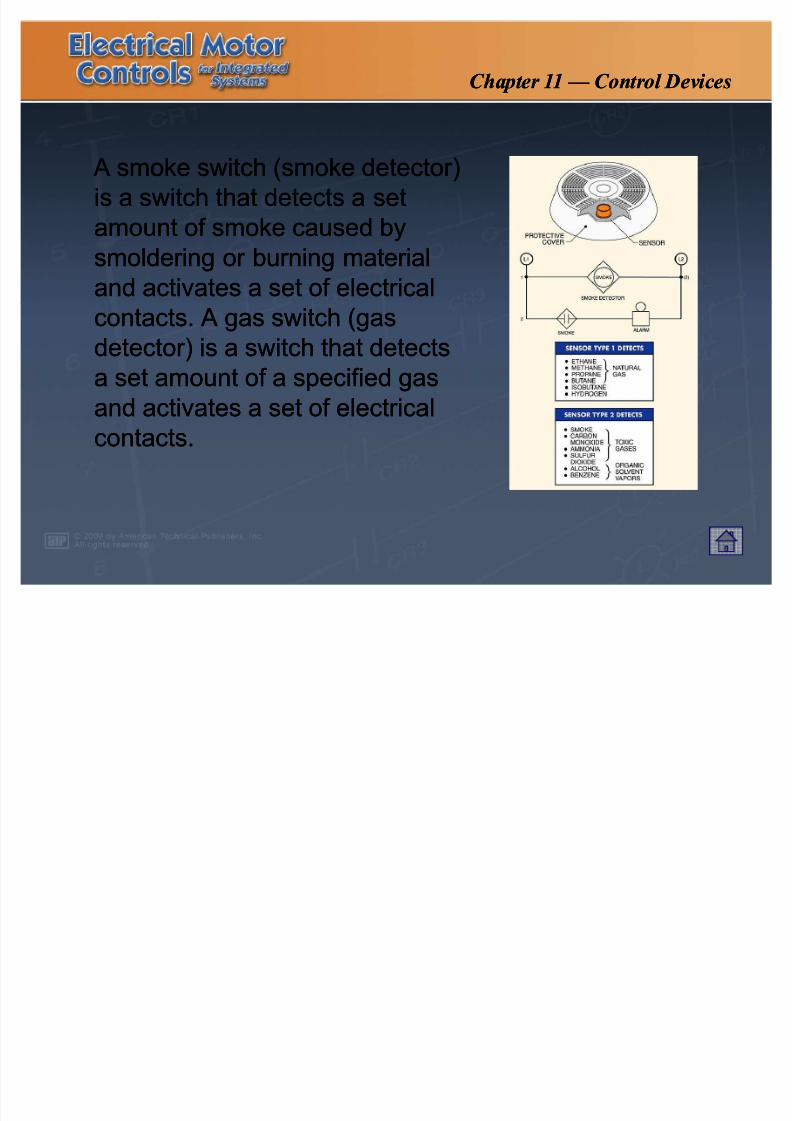
A smoke switch (smoke detector)
is a switch that detects a set
amount of smoke caused by
smoldering or burning material
and activates a set of electricalcontacts. A gas switch (gas
detector) is a switch that detects
a set amount of a specified gas
and activates a set of electricalcontacts.
A smoke switch (smoke detector)
is a switch that detects a set
amount of smoke caused by
smoldering or burning material
and activates a set of electricalcontacts. A gas switch (gas
detector) is a switch that detects
a set amount of a specified gas
and activates a set of electricalcontacts.
8/6/2019 C11 Control Devices
http://slidepdf.com/reader/full/c11-control-devices 37/60
Chapter 11 ² Control DevicesChapter 11 ² Control Devices
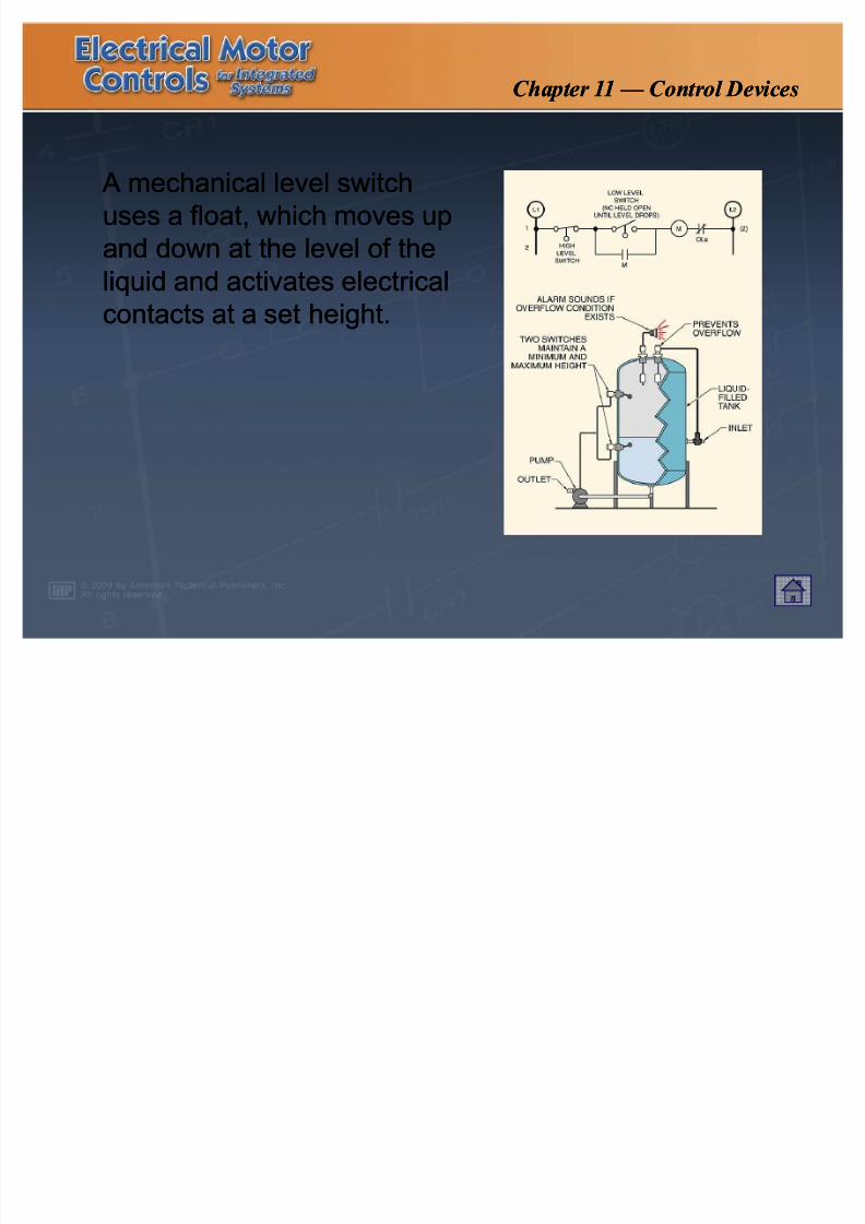
A mechanical level switch
uses a float, which moves up
and down at the level of the
liquid and activates electrical
contacts at a set height.
A mechanical level switch
uses a float, which moves up
and down at the level of the
liquid and activates electrical
contacts at a set height.
8/6/2019 C11 Control Devices
http://slidepdf.com/reader/full/c11-control-devices 38/60
Chapter 11 ² Control DevicesChapter 11 ² Control Devices
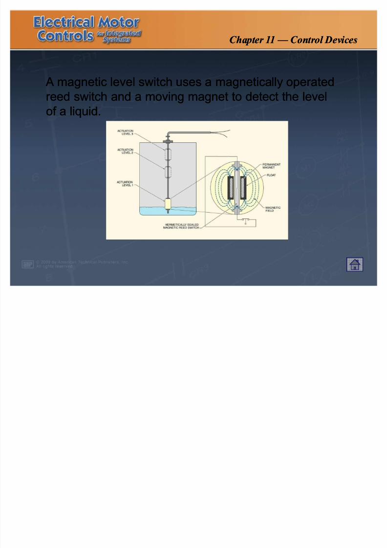
A magnetic level switch uses a magnetically operated
reed switch and a moving magnet to detect the level
of a liquid.
A magnetic level switch uses a magnetically operated
reed switch and a moving magnet to detect the level
of a liquid.

8/6/2019 C11 Control Devices
http://slidepdf.com/reader/full/c11-control-devices 39/60
Chapter 11 ² Control DevicesChapter 11 ² Control Devices
A conductive probe level
switch uses liquid to
complete the electrical
path between two
conductive probes.
A conductive probe level
switch uses liquid to
complete the electrical
path between two
conductive probes.
8/6/2019 C11 Control Devices
http://slidepdf.com/reader/full/c11-control-devices 40/60
Chapter 11 ² Control DevicesChapter 11 ² Control Devices
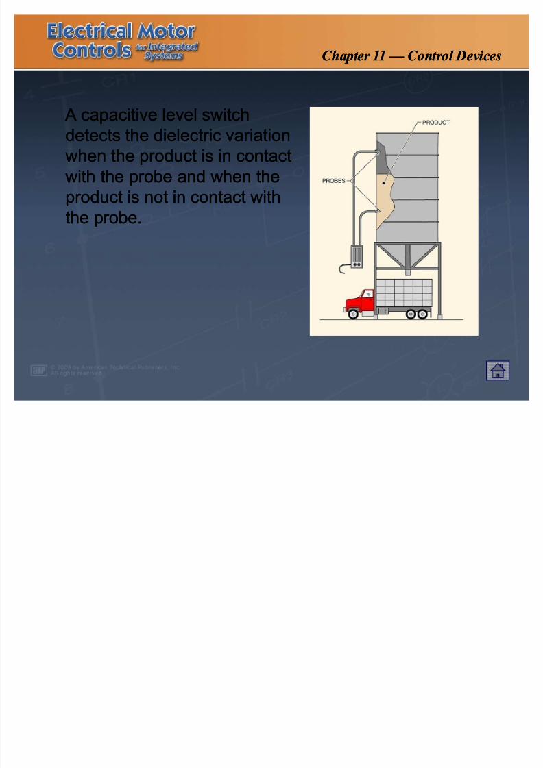
A capacitive level switch
detects the dielectric variation
when the product is in contact
with the probe and when the
product is not in contact withthe probe.
A capacitive level switch
detects the dielectric variation
when the product is in contact
with the probe and when the
product is not in contact withthe probe.
8/6/2019 C11 Control Devices
http://slidepdf.com/reader/full/c11-control-devices 41/60
Chapter 11 ² Control DevicesChapter 11 ² Control Devices
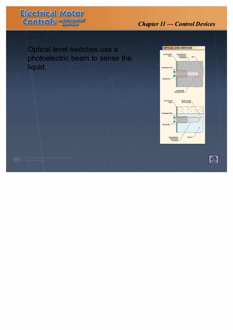
Optical level switches use a
photoelectric beam to sense the
liquid.
Optical level switches use a
photoelectric beam to sense the
liquid.
8/6/2019 C11 Control Devices
http://slidepdf.com/reader/full/c11-control-devices 42/60
Chapter 11 ² Control DevicesChapter 11 ² Control Devices
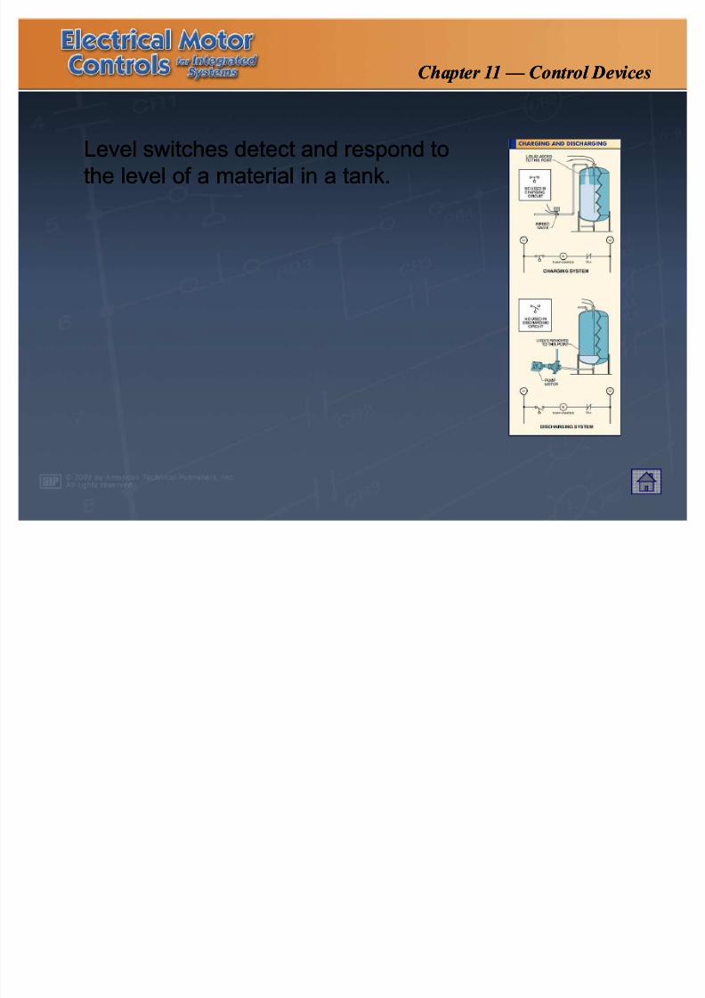
Level switches detect and respond to
the level of a material in a tank.
Level switches detect and respond to
the level of a material in a tank.

8/6/2019 C11 Control Devices
http://slidepdf.com/reader/full/c11-control-devices 43/60
Chapter 11 ² Control DevicesChapter 11 ² Control Devices
The distance controlled
in one-level control is
small. Any distance may
be controlled in two-level
control.
The distance controlled
in one-level control is
small. Any distance may
be controlled in two-level
control.

8/6/2019 C11 Control Devices
http://slidepdf.com/reader/full/c11-control-devices 44/60
Chapter 11 ² Control DevicesChapter 11 ² Control Devices
A temperature and level
control may be combined to
control the temperature and
level of a fluid.
A temperature and level
control may be combined to
control the temperature and
level of a fluid.
8/6/2019 C11 Control Devices
http://slidepdf.com/reader/full/c11-control-devices 45/60
Chapter 11 ² Control DevicesChapter 11 ² Control Devices
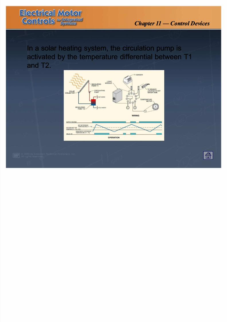
In a solar heating system, the circulation pump is
activated by the temperature differential between T1
and T2.
In a solar heating system, the circulation pump is
activated by the temperature differential between T1
and T2.
8/6/2019 C11 Control Devices
http://slidepdf.com/reader/full/c11-control-devices 46/60
Chapter 11 ² Control DevicesChapter 11 ² Control Devices
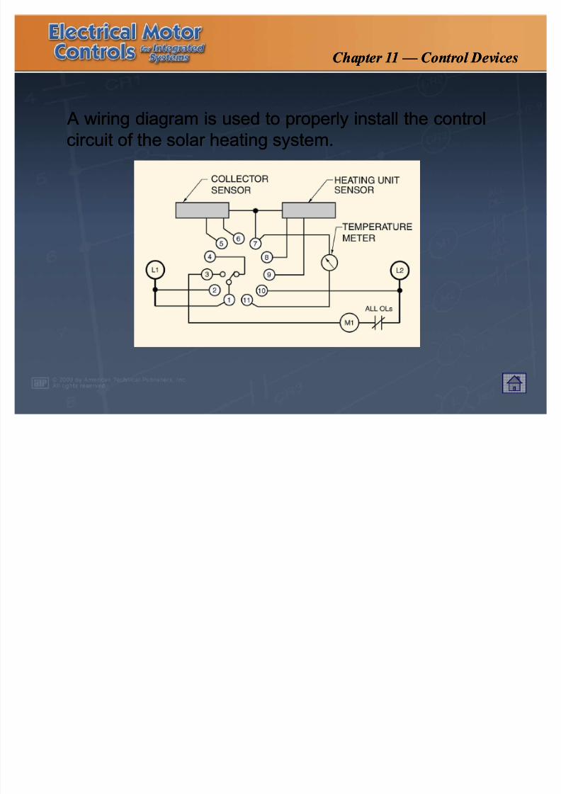
A wiring diagram is used to properly install the control
circuit of the solar heating system.
A wiring diagram is used to properly install the control
circuit of the solar heating system.
8/6/2019 C11 Control Devices
http://slidepdf.com/reader/full/c11-control-devices 47/60
Chapter 11 ² Control DevicesChapter 11 ² Control Devices
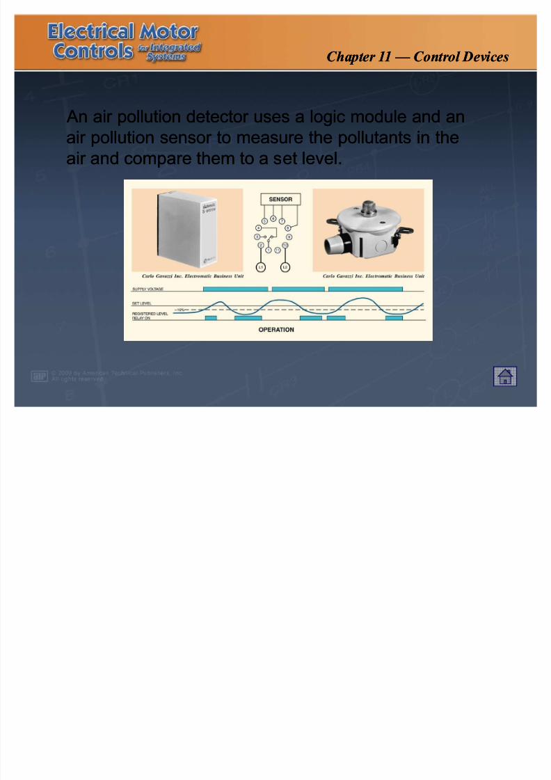
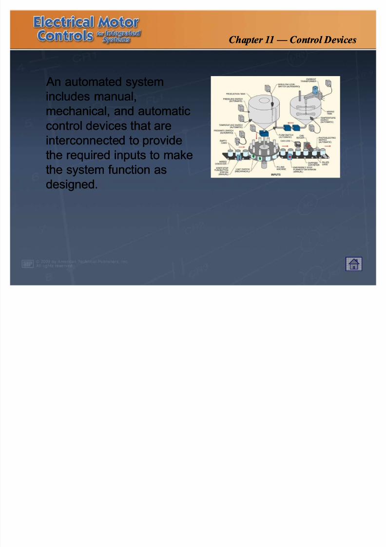
An air pollution detector uses a logic module and an
air pollution sensor to measure the pollutants in the
air and compare them to a set level.
An air pollution detector uses a logic module and an
air pollution sensor to measure the pollutants in the
air and compare them to a set level.
8/6/2019 C11 Control Devices
http://slidepdf.com/reader/full/c11-control-devices 48/60
Chapter 11 ² Control DevicesChapter 11 ² Control Devices
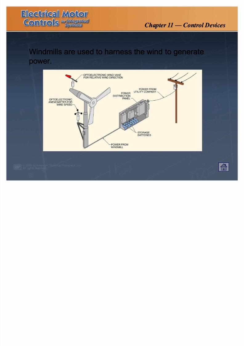
Windmills are used to harness the wind to generate
power.
Windmills are used to harness the wind to generate
power.
8/6/2019 C11 Control Devices
http://slidepdf.com/reader/full/c11-control-devices 49/60
Chapter 11 ² Control DevicesChapter 11 ² Control Devices
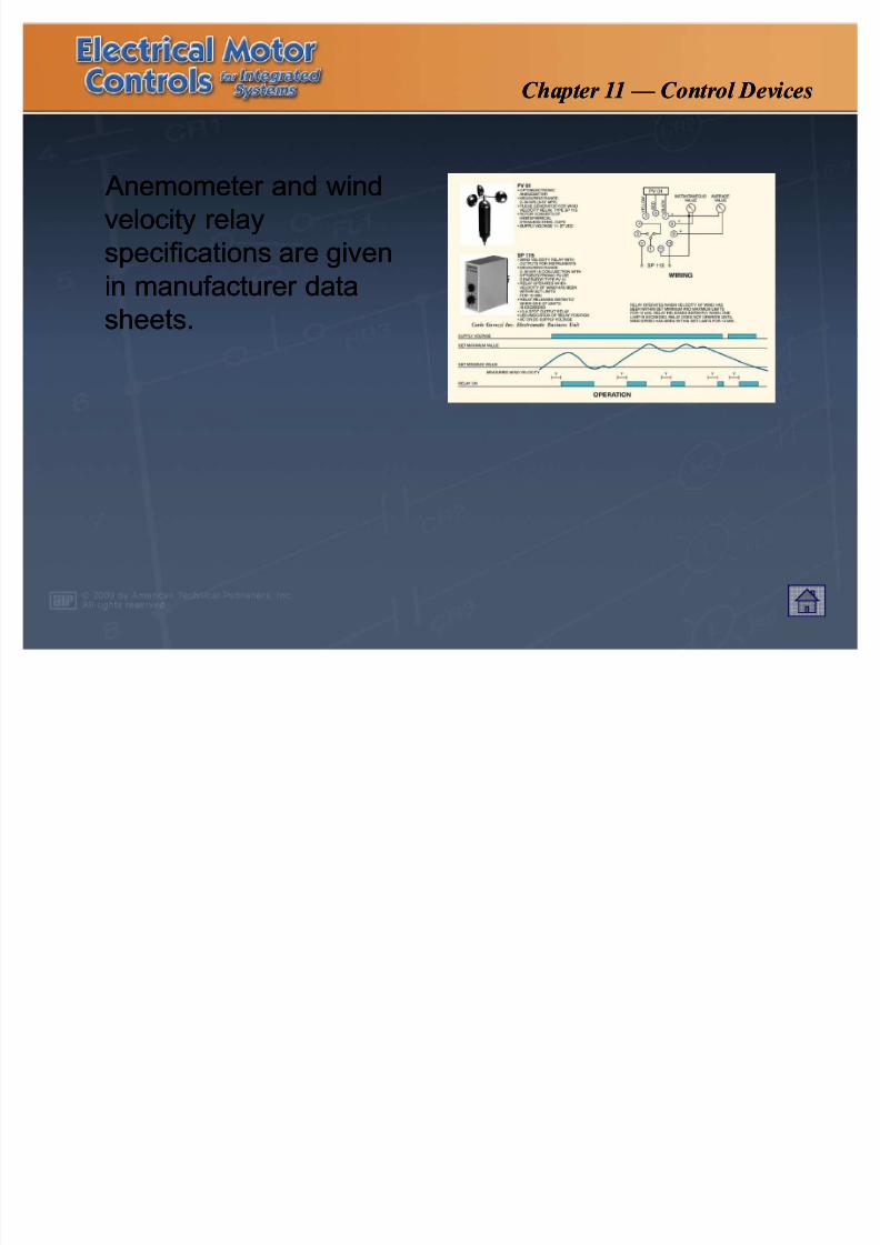
Anemometer and wind
velocity relay
specifications are given
in manufacturer data
sheets.
Anemometer and wind
velocity relay
specifications are given
in manufacturer data
sheets.
8/6/2019 C11 Control Devices
http://slidepdf.com/reader/full/c11-control-devices 50/60
Chapter 11 ² Control DevicesChapter 11 ² Control Devices
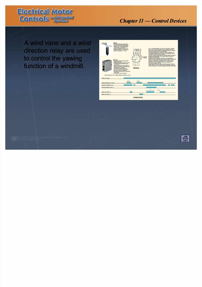
A wind vane and a wind
direction relay are used
to control the yawing
function of a windmill.
A wind vane and a wind
direction relay are used
to control the yawing
function of a windmill.
8/6/2019 C11 Control Devices
http://slidepdf.com/reader/full/c11-control-devices 51/60

8/6/2019 C11 Control Devices
http://slidepdf.com/reader/full/c11-control-devices 52/60
Chapter 11 ² Control DevicesChapter 11 ² Control Devices
Contact protection may be
added when switching large DC
and AC inductive loads to
prevent or reduce arcing at the
switch contacts.
Contact protection may be
added when switching large DC
and AC inductive loads to
prevent or reduce arcing at the
switch contacts.

8/6/2019 C11 Control Devices
http://slidepdf.com/reader/full/c11-control-devices 53/60
Chapter 11 ² Control DevicesChapter 11 ² Control Devices
A pressure relief valve may be
added to a circuit to protect a
pressure switch from excessive
pressure.
A pressure relief valve may be
added to a circuit to protect a
pressure switch from excessive
pressure.

8/6/2019 C11 Control Devices
http://slidepdf.com/reader/full/c11-control-devices 54/60
Chapter 11 ² Control DevicesChapter 11 ² Control Devices
Allow a distance of at least
three pipe inside diameters
(ID) on each side of the flow
switch when mounting a flow
switch.
Allow a distance of at least
three pipe inside diameters
(ID) on each side of the flow
switch when mounting a flow
switch.
8/6/2019 C11 Control Devices
http://slidepdf.com/reader/full/c11-control-devices 55/60
Chapter 11 ² Control DevicesChapter 11 ² Control Devices
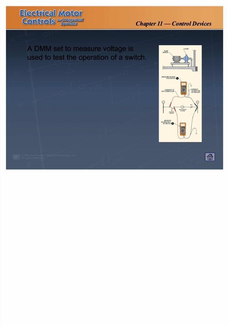
A DMM set to measure voltage is
used to test the operation of a switch.
A DMM set to measure voltage is
used to test the operation of a switch.
8/6/2019 C11 Control Devices
http://slidepdf.com/reader/full/c11-control-devices 56/60
Chapter 11 ² Control DevicesChapter 11 ² Control Devices
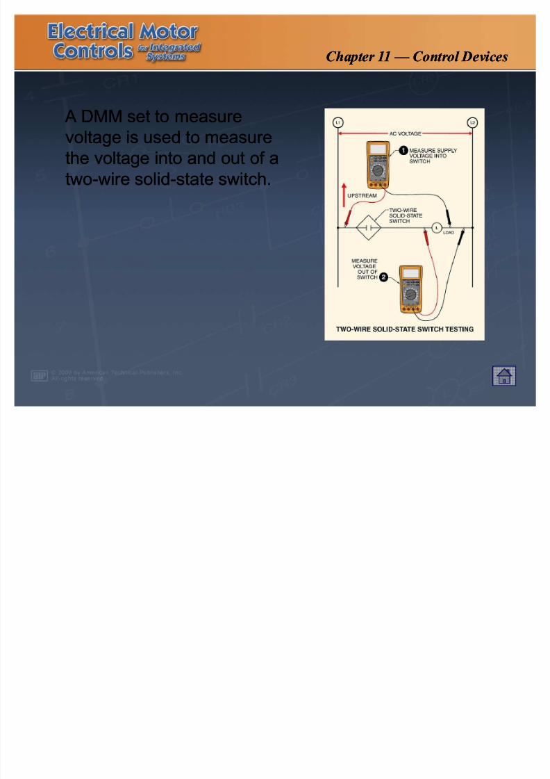
A DMM set to measure
voltage is used to measure
the voltage into and out of a
two-wire solid-state switch.
A DMM set to measure
voltage is used to measure
the voltage into and out of a
two-wire solid-state switch.
8/6/2019 C11 Control Devices
http://slidepdf.com/reader/full/c11-control-devices 57/60
Chapter 11 ² Control DevicesChapter 11 ² Control Devices
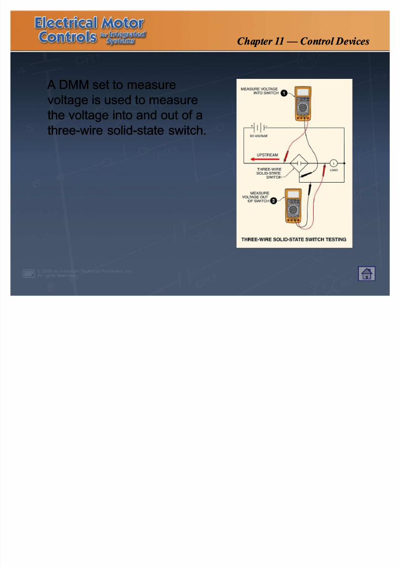
A DMM set to measure
voltage is used to measure
the voltage into and out of a
three-wire solid-state switch.
A DMM set to measure
voltage is used to measure
the voltage into and out of a
three-wire solid-state switch.
8/6/2019 C11 Control Devices
http://slidepdf.com/reader/full/c11-control-devices 58/60
Chapter 11 ² Control DevicesChapter 11 ² Control Devices
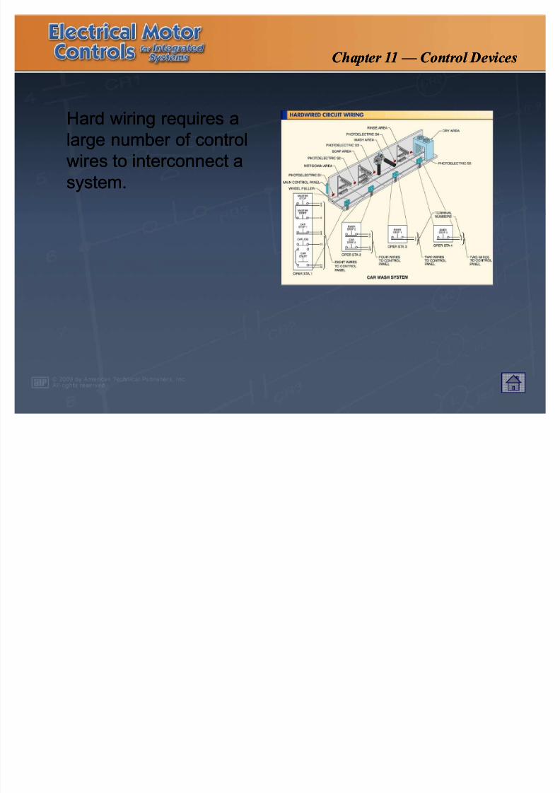
Hard wiring requires a
large number of control
wires to interconnect a
system.
Hard wiring requires a
large number of control
wires to interconnect a
system.
8/6/2019 C11 Control Devices
http://slidepdf.com/reader/full/c11-control-devices 59/60
Chapter 11 ² Control DevicesChapter 11 ² Control Devices
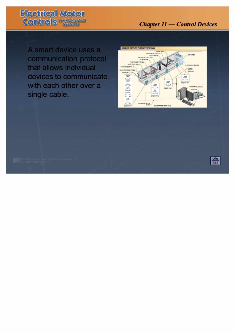
A smart device uses a
communication protocol
that allows individual
devices to communicate
with each other over asingle cable.
A smart device uses a
communication protocol
that allows individual
devices to communicate
with each other over asingle cable.
8/6/2019 C11 Control Devices
http://slidepdf.com/reader/full/c11-control-devices 60/60
Chapter 11 ² Control DevicesChapter 11 ² Control Devices
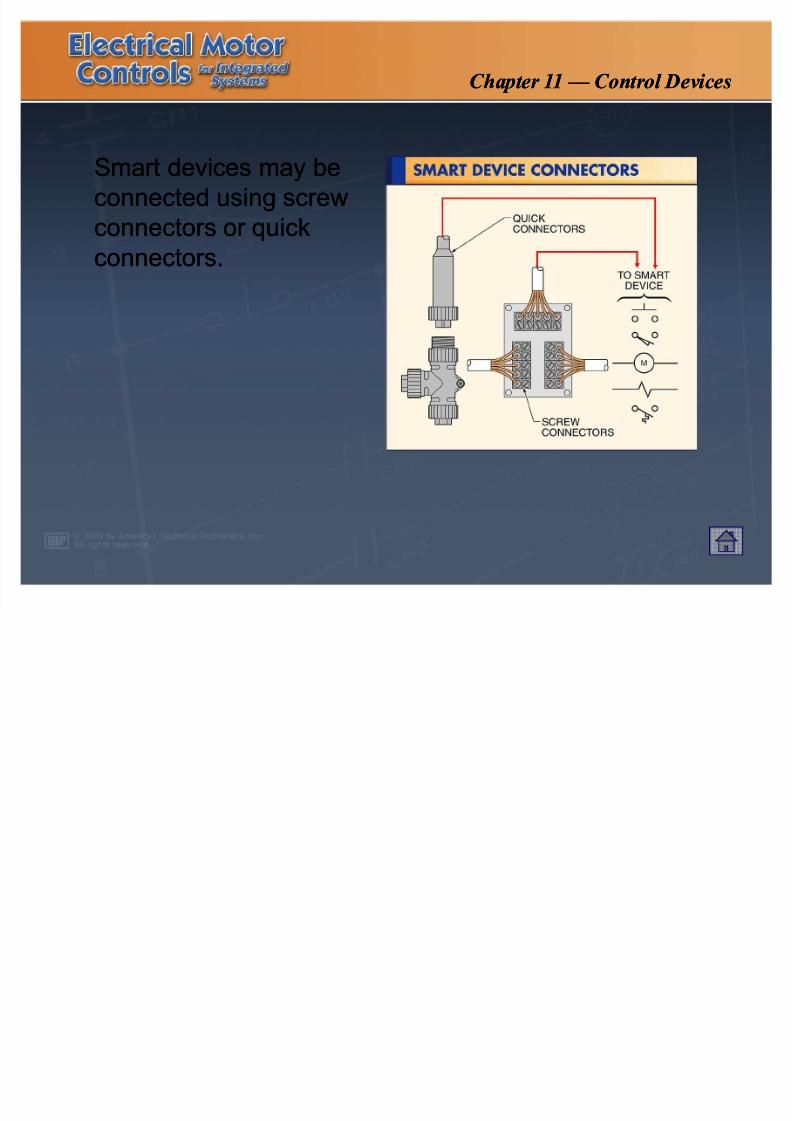
Smart devices may be
connected using screw
connectors or quick
connectors.
Smart devices may be
connected using screw
connectors or quick
connectors.