Embed Size (px)
Citation preview

MICCAI 2003. Lecture Notes in Computer Science, vol. 2879, pp. 336-343.
C-mode Real Time Tomographic Reflection for a
Matrix Array Ultrasound Sonic Flashlight
George Stetten 1,2,3
, Aaron Cois 1,2,
, Wilson Chang 1,2,3
, Damion Shelton 2,
Robert Tamburo 1,2
, John Castellucci 4, Olaf von Ramm
4
1
Department of Bioengineering, University of Pittsburgh, 2
Robotics Institute, Carnegie Mellon University, 3
University of Pittsburgh Medical Center 4
Department of Biomedical Engineering, Duke University
http://www.vialab.org
Abstract. Real Time Tomographic Reflection (RTTR), permits in situ
visualization of tomographic images, so that natural hand-eye coordination can
be employed directly during invasive procedures. The method merges the
visual outer surface of the patient with a simultaneous scan of the patient’s
interior, using a half-silvered mirror. A viewpoint-independent virtual image is
reflected precisely into the proper location. When applied to ultrasound, we call
the resulting RTTR device the sonic flashlight. We have previously
implemented the sonic flashlight using conventional 2D ultrasound. In this
paper we present the first images from a new sonic flashlight based on Real
Time 3D (RT3D) ultrasound, which uses a matrix array to electronically steer
the ultrasound beam at very high speed. We show in situ C-mode images,
which are parallel to the face of the transducer, of the hand and the cardiac
ventricles.
1 Introduction
In the practice of medicine, the standard method of viewing an image is to examine a
film or screen, rather than to look directly into the patient. A number of researchers
have worked to develop more natural ways to merge images with the perceptual real
world.1-4
We have previously reported the concept of Real Time Tomographic
Reflection (RTTR), and applied it successfully to ultrasound.5,6
Conventional
ultrasound produces a tomographic slice within the patient representing a set of 3D
locations that lie in a plane. The image of that tomographic slice, displayed on a flat
panel monitor at the correct size, may be reflected to occupy the same physical space
as the actual slice within the patient. If a half-silvered mirror is used, the patient may
be viewed through the mirror with the reflected image of the slice accurately
superimposed on the patient, independent of viewer location. The reflected image is
truly occupying its correct location and does not require any particular perspective to
be rendered correctly.
To accomplish RTTR, certain geometric relationships must exist between the
slice being scanned, the monitor displaying the slice, and the mirror. As shown in
Figure 1, the mirror must bisect the angle between the slice and the monitor. On the

MICCAI 2003. Lecture Notes in Computer Science, vol. 2879, pp. 336-343.
monitor, the image must be correctly translated and rotated so that each point in the
image is paired with its corresponding point in the slice. By fundamental laws of
optics, the ultrasound image will appear at its physical location, independent of
viewer position.
The RTTR ultrasound apparatus can be constructed in a number of
configurations. Figure 2 shows a recent version of a B-mode sonic flashlight, whose
images come from a standard ultrasound machine producing a conventional scan
along the axis of the
ultrasound transducer (B-
mode image). Thus, the flat
panel monitor is mounted as
shown, also along the axis of
the transducer with the
mirror bisecting the angle
between the transducer and
the flat-panel monitor. The
mirror is mounted
perpendicular to the axis, so
that the image on the flat
panel monitor is reflected to
occupy the space being
scanned by the ultrasound
transducer. The device is
Fig. 1 Schematic representation of an ultrasound RTTR device, or sonic flashlight.
A flat-panel monitor and an ultrasound transducer are placed on opposite sides of a half-silvered mirror to create an in situ virtual image.
half-silvered
mirror
flat-panel
monitor
ultrasound
transducer
half-silvered
mirror
flat-panel
monitor
ultrasound
transducer
Fig. 2 Recent prototype of the sonic flashlight,
showing the relationship of its components.

MICCAI 2003. Lecture Notes in Computer Science, vol. 2879, pp. 336-343.
designed to be held in one hand while performing an invasive procedure with the
other.
In Figure 3, the same sonic flashlight from Figure 2 is shown in use. A human
hand is seen with the transducer pressed against the soft tissue between the thumb and
index finger. While not a common target for clinical ultrasound, the hand was chosen
because it clearly demonstrates successful alignment. The external surfaces of the
hand are located consistent with structures within the ultrasound image. The
photograph cannot convey the strong sense, derived from stereoscopic vision, that the
reflected image is located within the hand. This sense is intensified by head motion
because the image remains properly aligned from different viewpoints. To one
experiencing the technique in person, ultrasound targets within the hand would clearly
be accessible to direct percutaneous injection, biopsy or excision.
2 Real Time 3D Ultrasound
This paper presents the first application (as far as we know) of RTTR to 3D
ultrasound. In particular, we have chosen Real Time 3D (RT3D) ultrasound, which
has been available commercially since the mid 1990’s through Volumetrics Medical
Imaging, Inc., a spin-off from Duke University, where we participated in development
of the technology.7,8
Volumetrics sold fewer than 25 scanners in the United States
and abroad. The particular scanner that we used for the C-mode sonic flashlight was
known as “T4”, the prototype for the commercialized scanners. Phillips, Inc., has
recently introduced a similar RT3D scanner commercially. Previously, all other
Fig. 3 Photograph from the viewpoint of the operator, showing a scan of the
hand using the apparatus in Figure 2. The reflected ultrasound image is merged with the direct visual image.

MICCAI 2003. Lecture Notes in Computer Science, vol. 2879, pp. 336-343.
commercial 3D ultrasound scanners gathered 3D data by mechanically “wobbling” a
conventional array through the third dimension. Since the matrix-array (Figure 4) of
the RT3D scanner, by contrast, has no moving parts, it can achieve rapid scan rates
(22 entire volumes per second), permitting the construction of a sonic flashlight with
no apparent latency. Although developed originally for cardiac applications, where
high speed is essential, the same speed is also well suited to real-time guidance of
invasive procedures.
Given the high-speed volumetric data from the Duke RT3D ultrasound machine,
we can generate in situ slices with any orientation relative to the transducer For
example, the scanner permits two orthogonal B-mode slices to be visualized
simultaneously, as well as a so-called “C-mode” slice, parallel to the face of the
transducer at any depth within the pyramid.
3 C-Mode Version of the Sonic Flashlight
A diagram of our C-mode sonic flashlight is shown in Figure 5 and the actual
apparatus is shown in Figure 6. Unlike the B-mode sonic flashlight in Figures 1-3,
the flat panel monitor in the C-mode sonic flashlight is mounted perpendicular to the
ultrasound probe, so that its reflection occupies a C-mode slice on the other side of
Fig. 4 The conventional 2D ultrasound scanner uses a row of transducer elements to
steer the direction of transmission and reception along the azimuth dimension, capturing
a single sector or B-mode slice (left). The Real Time 3D Ultrasound (RT3D) scanner
uses a matrix-array to steer in both azimuth and elevation, capturing an entire round-bottomed “pyramid” of data (right).
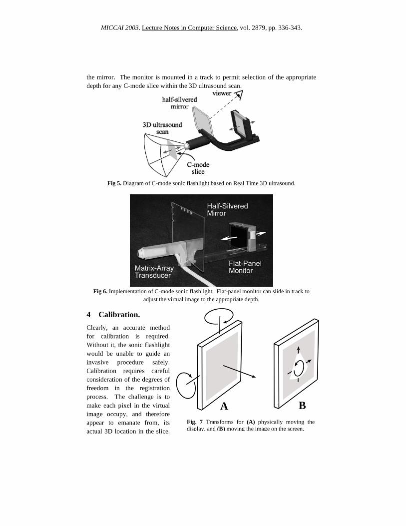
MICCAI 2003. Lecture Notes in Computer Science, vol. 2879, pp. 336-343.
the mirror. The monitor is mounted in a track to permit selection of the appropriate
depth for any C-mode slice within the 3D ultrasound scan.
Fig 5. Diagram of C-mode sonic flashlight based on Real Time 3D ultrasound.
Fig 6. Implementation of C-mode sonic flashlight. Flat-panel monitor can slide in track to
adjust the virtual image to the appropriate depth. 4 Calibration.
Clearly, an accurate method
for calibration is required.
Without it, the sonic flashlight
would be unable to guide an
invasive procedure safely.
Calibration requires careful
consideration of the degrees of
freedom in the registration
process. The challenge is to
make each pixel in the virtual
image occupy, and therefore
appear to emanate from, its
actual 3D location in the slice.
Fig. 7 Transforms for (A) physically moving the
display, and (B) moving the image on the screen.
A B
MICCAI 2003. Lecture Notes in Computer Science, vol. 2879, pp. 336-343.
For the sake of this experiment we consider only the geometric transform of a rigid
body, i.e., we assume that the ultrasound slice is displayed without distortion at its
correct scale on a perfectly flat monitor (Figure 7). The geometric transform required
to superimpose the virtual image onto the slice can be represented as two sets of
translations and rotations, each of which has 3 degrees of freedom. The first (2
rotations and 1 translation) allows the flat panel display to be moved into its correct
plane, making the virtual image coplanar with the actual ultrasound slice. We can
achieve this by physically moving the display in its track, and by ensuring that the
display and the mirror are both parallel to the face of the ultrasound transducer. The
second (two translations and one rotation) are achieved by adjusting the image of the
ultrasound slice on the flat panel monitor.
For the initial prototype of the C-mode Sonic Flashlight, calibration was achieved
by adjusting the depth of the virtual image to the known depth of the slice as
determined by the scanner. Center location and aspect ratio (1:1) of the image on the
screen was adjusted by eye. Scale was then adjusted visually, to produce matching
motion between the ultrasound image and surface landmarks as the transducer was
passed over the target.
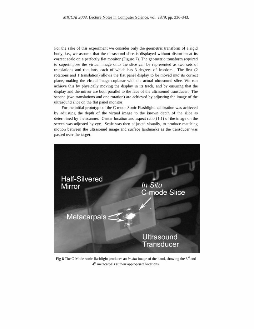
Fig 8 The C-Mode sonic flashlight produces an in situ image of the hand, showing the 3rd
and
4th
metacarpals at their appropriate locations.

MICCAI 2003. Lecture Notes in Computer Science, vol. 2879, pp. 336-343.
5 Results
Figure 8 shows a C-mode image of the bones in the hand. The C-mode image appears
more naturally “illuminated” by the ultrasound than a B-mode image, because the C-
mode slice cuts across the ultrasound beam and its pixels do not block each other
along the ultrasound beam. The C-mode image therefore does not include the
shadows that normally streak across a B-mode image. Structures in the C-mode
image appear to reflect ultrasound the way they would reflect light. Whereas the B-
mode Sonic Flashlight “looks” like a flashlight, the C-mode Sonic Flashlight “acts”
like a flashlight. Figure 9 shows the left ventricle (LV) and right ventricle (RV) of a
human heart in their appropriate locations.
Fig. 9 Cardiac ventricles (LV = left ventricle, RV = right ventricle) seen in situ using the C-
mode sonic flashlight. Insert is magnified to show the correct shape of each ventricle. The LV
is round, while the RV is crescent-shaped.

MICCAI 2003. Lecture Notes in Computer Science, vol. 2879, pp. 336-343.
5 Discussion Superimposing ultrasound images on human vision using RTTR may improve an
operator’s ability to find targets while avoiding damage to neighboring structures and
facilitating interpretation of ultrasound images by relating them spatially to external
anatomy. As such, it holds promise for increasing accuracy, ease, and safety during
percutaneous biopsy of suspected tumors, amniocentesis, fetal surgery, brain surgery,
insertion of catheters, and many other interventional procedures. The extension of
RTTR to matrix array Real-Time 3D ultrasound offers the ability to visualize in situ
slices other than the conventional B-mode, including C-mode slices parallel to the
face of the transducer. This may be advantageous in particular invasive procedures
by allowing slice orientations with greater accessibility from the body surface.
The sonic flashlight has been awarded a US Patent. 9
References 1. State, A., Livingston, M., Garret, W., Hirota, G., Whitton, M., Pisano, E. &
Fuchs, H., Technologies for Augmented Reality Systems: Realizing Ultrasound-
Guided Needle Biopsies. ACM SIGGRAPH, New Orleans, LA, 439-446 (1996).
2. Rosenthal, M., State, A., Lee, J., Hirota, G., Ackerman, J., Keller, K., Pisano, E.,
Jiroutek, M., Muller, K. & Fuchs, H., Augmented Reality Guidance for Needle
Biopsies: A Randomized, Controlled Trial in Phantoms. MICCAI 2001, Lecture
Notes in Computer Science 2208, Springer-Verlag, 240-248.
3. Sauer, F., Khamene, A., Bascle, B., Schimmang, L., Wenzel, F. & Vogt, S.,
Agumetned reality visualization of ultrasound images: System description,
calibration, and features. International Symposium on Augmented Reality 2001,
IEEE and ACM, New York City, 30-39.
4. Masamune, K., Fichtinger, G., Deguet, A., Matsuka, D. & Taylor, R., An Image
Overlay System with Enhanced Reality for Percutaneous Therapy Performed
Inside CT Scanner. MICCAI 2002, Lecture Notes in Computer Science, 2489,
Springer-Verlag, 77-84.
5. Stetten, G., Chib, V. & Tamburo, R., System for Location-Merging Ultrasound
Images with Human Vision. Applied Imagery Pattern Recognition (AIPR) 2000,
Workshop, IEEE Computer Society, Washington, DC, 200-205.
6. Stetten, G. & Chib, V., Overlaying ultrasound images on direct vision. Journal of
Ultrasound in Medicine 20, 235-240 (2001).
7. von Ramm, O. T., Smith, S. W. & Pavy, H. G., Jr., High-speed ultrasound
volumetric imaging system - Part II: Parallel processing and image display. IEEE
Transactions on Ultrasonics, Ferroelectrics, and Frequency Control 38, 109-115
(1991).
8 Stetten, G., Ota, T., Ohazama, C., Fleishman, C., Castelucci, J., Oxaal, J., Ryan,
T., Kisslo, J. & Ramm, O. v., Real-Time 3D Ultrasound: A New Look at the
Heart. Journal of Cardiovascular Diagnosis and Procedures 73-84 (1998).
9 Stetten, G. U.S. Patent no. 6,599,247, “System and Method for Location-Merging
of Real-Time Tomographic Slice Images with Human Vision,” July 29, 2003.


![[Array, Array, Array, Array, Array, Array, Array, Array, Array, Array, Array, Array]](https://img.pdfslide.us/doc/110x75/56816460550346895dd63b8b/array-array-array-array-array-array-array-array-array-array-array.jpg)