Embed Size (px)
Citation preview

C MANUALPOWER FLAME INCORPORATED

If you smell gas:
1. Open windows.
2. Do not touch electrical switches.
3. Extinguish any open flame.
4. Call your gas supplier immediately.
FOR YOUR SAFETYDo not store or use gasoline or otherflammable liquids and vapors in thevicinity of this or any other appliance.
WARNINGImproper installation, adjustment,alteration, service or maintenance cancause injury or property damage. Refer tothis manual. For assistance or additionalinformation consult a qualified installer,
service agency or the gas supplier.
Rev.202
NOTICEEffective 4/1/94 Underwriters Laboratoriesrequire that all gas burners firing at inputsof 2,500 MBH and under be supplied withtwo gas safety valves or one gas valve withproof of closure (Valve seal over travel). Thephotos in this manual may not depict thesespecific components. All U.L. listed productsshipped after 4/1/94 will comply with U.L.
requirements.

MANUAL C888C1
Rev. 106
Principal of OperationPower Flame Type C Burners incorporate the principles ofpressure atomization for oil and multiple orifice, venturioperation for gas. The total package utilizes the forceddraft, flame retention concept. The Type C burner is listedand labeled by Underwriters Laboratories, Inc. Capacities,when fired at 0.2" w.c. positive combustion chamberpressure, range from 3 to 136.4 GPH of commercial grade#2 fuel oil and/or 98 to 19,100 CFH of natural gas. Air forcombustion is furnished by an integrally mounted combus-tion air fan. The Power Flame packaged combustionsystem can be operated under positive or negative furnacepressures with clean, efficient combustion in a wide rangeof combustion chamber conditions. (Consult page 6 forappropriate ratings.)
The Power Flame C Burner is a totally packaged andfactory tested combustion system offering single unitresponsibility. The package incorporates accurate controlof the fuel-air ratio throughout the firing range with theresultant controlled flame patterns and clean combustionfor maximum efficiency.
Power Flame Type C Burners are designed to producegreater flame turbulence and reduce flame size. As aresult, they require less combustion volume for completecombustion and can be easily fired under positive furnacepressure. Forced draft pressurized operation requiresstacks of smaller diameter and height.
Combustion air flow is controlled by a multi-louvereddamper assembly. The combustion air is supplied by anintegral motor-driven blower, which discharges into theburner blast tube assembly. High turbulence flow iscontrolled by means of an adjustable fan diffuser system.Various system mode operations are obtained byapplying appropriate control valves and fuel/air actuators.Units are capable of operating in modes consistent withspecific demand requirements, from fixed or on-off throughfull modulation.
The air/fuel ratio is established at the time of start-up andproven with combustion test equipment to provide thelowest practical oxygen with a clean flame.
13 Combustion Chamber - General
14 Combustion Chamber Data
3. Mechanical Operation of
Fuel/Air Control Modes
15 Gas - On-Off
15 Gas - Low-High-Off and Low-High-Low
16 Gas - Full Modulation
16 Oil - On-Off
17 Oil - Fixed Air Low Fire Start
18 Reduced Air Low Fire Start System
19 Oil - Low-High-Off and Low-High-
Low with Webster Oil Pump
20 Oil - Low-High-Off and Low-High-
Low with Suntec 2-Step Oil Pump
21 Oil - Full Modulation
22 Diffuser Position Adjustment for Gas,
Oil or Gas/Oil Burners
22 Gas or Gas/Oil Burner Fuel/Air
Premix Adjustment
22 Gas/Oil - Linkage Arrangement for
Full Modulation - Standard System
22 Gas/Oil - Detail and Adjustments on
Modulating VaricamTM Characterized
Fuel Metering System
4. Start Up, All Fuel
23 All Fuels - General Start Up Procedures
23 Information on Fuel/Air Modes of
Operation for Combination Gas/Oil
Units
24 Burner Start Up and Service Test
Equipment Required
5. Gas Start Up
25 General Gas Start Up Procedure
6. Oil Start Up
28 General Oil Start Up Procedure
7. Servicing and Component
Adjustments
31 General Information on Internal
By-pass Oil Nozzle Systems
31 Internal Bypass Nozzle Data
34 Oil Nozzle Flow Rates
34 Oil Nozzle Servicing
34 Oil Pump or Oil Flow Problems
35 Direct Spark Oil Ignition
Adjustments
35 Oil Drawer Assembly Diagrams
36 Gas/Oil Burner Firing Head
Cutaway
36 Gas and Gas/Oil Gun Assembly
Diagrams
37 Gas Burner Orifice Sizing
38 Limiting Orifice Information
39 Gas Pilot Ignition Adjustment
39 Pilot Spark Ignition Electrode
Adjustment
40 Gas Pilot Flood Test
41 Flame Safeguard Control Flame
Signal Values
41 CO2-O2 Ratio Curves for Fuel
Oils and Gases
42 Trouble Shooting Suggestions
8. Maintenance
44 General
45 Periodic Check List
9. Burner Start Up Information
and Test Data
46 Combustion Analysis
47 Control Settings
51 10. Gas and Oil Burner Owner
Operating Instructions
Rev.304
CONTENTS
1. GENERAL PRODUCT INFORMATION
1. General Product Information
1 Principal of Operation
2 Model Identification
2 Unpacking and Handling
2 Warranty and Spare Parts
3 General Component Information
3 Burner Component Identification
On-Off Fuel/Air Control Modes
4 Burner Component Identification
Low-High-Off or Low-High-Low
Fuel/Air Control Modes
4 Burner Component Identification
Modulating Fuel/Air Control Modes
5 Standard Burner Dimensional
Data
6 Standard Burner Ratings and
Component Data
7 Control Panel Information
2. Installation
9 Gas Supply Piping - General
9 Gas Supply Line Sizing Charts
10 Gas Train Components Supplied
for Standard UL Burner
Requirements
10 Gas Train Piping Schematics
for Standard UL Burner
Requirements
11 Oil Supply Piping - General
11 Oil Pump Suction Capacity and
Filter Selection Information
12 Oil Line Sizing Charts
12 Oil Pump Detail
13 Multiple Burner System Oil
Piping Schematic
13 Combustion Air Requirements
13 Burner Mounting - General
A Flame-Safeguard Programmer, available in variouscontrol sequences, programs the firing cycle. Theoperating cycle is sequenced to ensure normal and safeconditions before fuel can be introduced into the combus-tion area. The complete firing cycle is supervised toensure that ignition of main flame is properly establishedand maintained. Both direct spark and gas pilot ignitionsystems are available. Flame monitoring is provided byoptical scanner of the cesium oxide, lead sulfide, cadmiumsulfide or ultraviolet types.
The limit circuit includes the operating limit control tomaintain set operating pressure or temperature, as well asa high limit control to guard against excessive pressure ortemperature. Low water and other similar safety controlscan be interlocked into the burner control system to fitspecific job and/or code requirements.
The control circuit is normally 120 volts. A control circuittransformer may be furnished to provide the 120 voltcontrol circuit for polyphase motor applications. Thecontrol circuit is frequently interlocked with the polyphasemotor circuit to shut down the burner in the event of aninterruption of the motor current.
Power Flame Type C burners are capable of firing single ormulti-fuel applications. (See model selection, page 6, Table 2.)
For multi-fuel burners, fuel changeover may beprovided by automatic control, influenced by outsidetemperature or manual switching. Interlocking relaysand timers ensure safe changeover of fuels by meansof a timed interruption of firing, long enough to causea complete recycle of the programmer.
The prewired Control Panel is mounted and wired as anintegral part of the burner in accordance withrecommendations of Underwriters Laboratories, Inc. andNational Electrical Code. Components are wired tonumbered terminal strips. Panels and burners arefactory fire tested before shipment. Comprehensivewiring and gas and/or oil piping diagrams are furnishedwith each burner in accordance with individual job orapplication requirements. Wall mounted or free-standingcontrol panels are also available.
Power Flame C burners are available with controlsystems to comply with the requirements of FactoryMutual, Industrial Risk Insurers and any special state,municipal, local and utility company codes, includingNew York City Department of Buildings (MEA), NYCDepartment of Environmental Protection, Commonwealthof Massachusetts, State of Connecticut Fire Marshall,Illinois School Code and others.
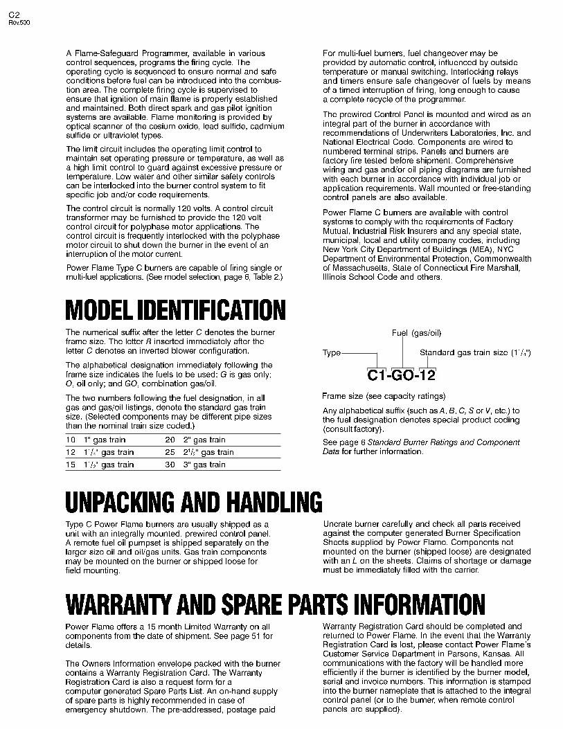
MODEL IDENTIFICATIONThe numerical suffix after the letter C denotes the burnerframe size. The letter R inserted immediately after theletter C denotes an inverted blower configuration.
The alphabetical designation immediately following theframe size indicates the fuels to be used: G is gas only;O, oil only; and GO, combination gas/oil.
The two numbers following the fuel designation, in allgas and gas/oil listings, denote the standard gas trainsize. (Selected components may be different pipe sizesthan the nominal train size coded.)
Any alphabetical suffix (such as A, B, C, S or V, etc.) tothe fuel designation denotes special product coding(consult factory).
See page 6 Standard Burner Ratings and ComponentData for further information.
10 1" gas train 20 2" gas train
12 11/4" gas train 25 21/2" gas train
15 11/2" gas train 30 3" gas train
Fuel (gas/oil)
Type Standard gas train size (11/4")
Frame size (see capacity ratings)
C1-GO-12
UNPACKING AND HANDLINGType C Power Flame burners are usually shipped as aunit with an integrally mounted, prewired control panel.A remote fuel oil pumpset is shipped separately on thelarger size oil and oil/gas units. Gas train componentsmay be mounted on the burner or shipped loose forfield mounting.
Uncrate burner carefully and check all parts receivedagainst the computer generated Burner SpecificationSheets supplied by Power Flame. Components notmounted on the burner (shipped loose) are designatedwith an L on the sheets. Claims of shortage or damagemust be immediately filled with the carrier.
Power Flame offers a 15 month Limited Warranty on allcomponents from the date of shipment. See page 51 fordetails.
The Owners Information envelope packed with the burnercontains a Warranty Registration Card. The WarrantyRegistration Card is also a request form for acomputer generated Spare Parts List. An on-hand supplyof spare parts is highly recommended in case ofemergency shutdown. The pre-addressed, postage paid
WARRANTY AND SPARE PARTS INFORMATIONWarranty Registration Card should be completed andreturned to Power Flame. In the event that the WarrantyRegistration Card is lost, please contact Power Flame�sCustomer Service Department in Parsons, Kansas. Allcommunications with the factory will be handled moreefficiently if the burner is identified by the burner model,serial and invoice numbers. This information is stampedinto the burner nameplate that is attached to the integralcontrol panel (or to the burner, when remote controlpanels are supplied).
C2Rev.500

COMPONENT INFORMATION-GENERALThe contents of this manual are general in nature,due to the wide variety of equipment specifications,insurance requirements and state, local and othercodes.
1. Blower Motor2. Blast Tube3. Air Inlet Housing4. Air Inlet Damper Manual Adjustment
Arms5. Air Flow Switch6. Drawer Assembly Cover Plate7. Drawer Assembly Adjustment8. Air Diffuser9. Flame Retention Ring
10. Gas Pilot Regulator11. Gas Pilot Solenoid Valve12. Gas Pilot Test Tee13. Gas Pilot Assembly14. Gas Pilot Ignition Transformer15. Flame Scanner (Detector)16. Orifice Tee with Gauge Test Port17. Automatic Gas Valve18. Leakage Test Cock19. Oil Pump20. Oil Solenoid Valve21. Control Panel22. On-Off Switch23. Fuel Selector Switch24. Hinged (Total Access) Top Section25. Light and Switch Circuit Board26. Removable Total Access Door27. Optional Board for Sequence Indicator Lights
The computer generated Burner Specification Sheetsshipped with the burner represent the as built version ofyour specific Power Flame combustion system. Partnumbers and component descriptions will match thosecomponents supplied. A duplicate set of BurnerSpecification Sheets is available through Power Flame�sCustomer Service Department.
Figure 1
Burner Component IdentificationTypical for Model CR-GO with On-Off Fuel/Air Control Modes of Operation.*
*The components and arrangements shownare typical for a Model CR-GO combinationgas/oil burner. Gas only or oil only units willhave similar components relating to theirspecific fuel. In some cases, the type ofcomponents and/or their arrangement mayvary from this depiction. For specifics onyour system, refer to the technical informa-
tion supplied with the burner.
C3Rev.703
24
27
26
21
11
10
2
1
2
13
87 6161817
26
21 24 19 3 4
15
12
1 14
22
23
9
20
25
5

Figure 2
Burner Component IdentificationTypical for Model C-GO with Low-High-Off or Low-High-Low Fuel/Air Control Modes of Operation.*
1. Blower Motor2. Blast Tube3. Air Inlet Housing4. Air Flow Switch5. Air Diffuser6. Flame Retention Ring7. Gas Pilot Regulator8. Gas Pilot Solenoid Valve9. Gas Pilot Test Tee
10. Gas Pilot Assembly11. Gas Pilot Ignition Transformer12. Flame Scanner (Detector)13. Orifice Tee With Gauge Test Port14. Motorized Gas Valve (Low-High-Off
or Low-High-Low)15. Air Damper Drive Linkage Assembly16. Leakage Test Cock17. Gas Premix Adjustment (Optional
Feature)18. Oil Pump19. Hydraulic Damper Actuator20. Oil Nozzle21. Low-High-Off or Low-High-Low Oil Control Train22. Control Panel23. Hinged (Total Access) Top Section24. Removable Total Access Door25. Test Port
*The components and arrangements shownare typical for a Model C combinationgas/oil burner. Gas only or oil onlyunits will have similar componentsrelating to their specific fuel. In somecases, the type of components and/or theirarrangements may vary from this depiction.For specifics on your system, refer to thetechnical information supplied with theburner.
Figure 3
Burner Component IdentificationTypical for Model C-GO with Modulating Fuel/Air Control Modes of Operation.*
1. Blower Motor2. Blast Tube3. Air Inlet Housing4. Air Inlet Damper Cross Connecting Linkage5. Air Flow Switch6. Flame View Port7. Drawer Assembly Cover Plate8. Drawer Assembly Adjustment9. Air Diffuser
10. Flame Retention Ring11. Gas Pilot Regulator12. Gas Pilot Solenoid Valve13. Gas Pilot Test Tee14. Gas Pilot Assembly15. Gas Pilot Ignition Transformer16. Flame Scanner (Detector)17. Modulating Butterfly Gas Valve18. Modulating Drive Motor19. Jack Shaft and Drive Linkage20. Gas Pressure Gauge Test Port21. Gas Premix Adjustment (Optional
Feature)
23 4 5
8
7
22
24
5 6 2
1 12
16
14
6
10
19 21 22
18
151
3
8 715 6
3
32
27
22 25 4
20
17
2
2
1411
9
30 29
28
12
24
19
26
12
1311 25
17
20
18 35
31
C4Rev.703

C5Rev.304
Table 1
Standard Dimensions (Inches)
A
341/8
391/8
44
50
50
497/8
5111/16
569/16
B
313/16
41/2
51/4
61/4
61/4
61/4
81/8
81/8
B(R)
59/16
61/8
7
75/16
75/16
75/16
101/8
101/8
C
141/2
147/8
165/8
187/8
187/8
187/8
245/16
271/8
C(R)
141/2
14
151/4
1711/16
1711/16
1711/16
223/8
275/8
D
45/8
51/4
6
7
7
73/4
83/4
83/4
E
121/4
14
16
181/2
181/2
197/8
18
20
Gas/Oil
20
20
223/8
28
261/2
261/2
2113/16
243/8
STD
31/4
4
41/2
6
6
5
47/8
31/4
K
101/4
101/4
101/4
101/4
101/4
101/4
91/8
91/8
X
71/4
81/2
10
12
12
131/2
131/2
131/2
H
71/4
83/4
101/8
121/8
121/8
135/8
155/8
155/8
ST.Oil
123/4
13
141/4
18
18
18
2113/16
243/8
I
73/8
81/2
111/2
141/4
141/4
141/8
137/8
121/4
L
171/8
187/8
22
265/8
265/8
261/2
261/2
247/8
S
125/8
133/8
151/2
191/8
191/8
19
19
175/16
MAX*
43/4
63/4
8
9
9
113/4
111/4
95/8
F** G
11
12
32
30 5 15
33
2
1 16
23
10
* This dimension may be increased. Consult factory.Note: Dimensions shown are standard, but may vary due to
component changes, etc.
** This dimension depicts space required to accommodatea standard gas train, standard oil valves and standardburner mounted pump.
Model
C1
C2
C3
C4
C5
C6
C7(B)
C8
34
9
13
14
NOTE:Add 3/8" to �H� for size of opening inboiler front plate.
* Dimension may be reduced by 101/4" bymoving panel to appropriate alternatelocation.
5/8� Dia.4 Holes
5/8� Dia.4 Holes
Figure 5
Model CR Configuration
Figure 4
Model C Configuration
Standard Burner Dimensional Data
NOTE:Add 3/8" to �H� for size of opening inboiler front plate.
* Dimension may be reduced by 101/4" bymoving panel to appropriate alternatelocation.
22. Oil Pump23. Oil Nozzle24. Modulating Oil Valve25. Oil Nozzle Bypass Pressure Test Tee26. Nozzle Return Line Check Valve27. Control Panel28. On-Off Switch29. Fuel Selector Switch30. Hinged (Total Access) Top Section31. Light and Switch Circuit Board32. Removable Total Access Door33. Motorized Gas Valve34. Test Port35. Optional Board for Sequence
Indicator Lights
NOTE:See page 22, Figure 28 for depiction of characterized fuel/aircontrol system.
*The components and arrangements shown are typical for aModel C-GO combination gas/oil burner. Gas only (C-G) or oilonly (C-O) units will have similar components relating to theirspecific fuel.
In some cases, the type of components and/or theirarrangement may vary from this depiction. For specifics onyour system, refer to the technical information supplied withthe burner.
CADST.Oil
11
111/2
-
-
-
-
-
-

A. See page 2 for further model number information.
B. The flame sensor shown - UV (Ultra Violet) or CC (Cad Cell). Other flamesensors such as Lead Sulfide and photo cell are available to comply withspecifications or codes.
C. If separate pump is supplied, HP may be reduced. For positive pressureapplications on C1 burners with integral pump firing over 8 GPH or some OEMboilers, a 1/2 HP motor and oversized fan are required on oil and gas/oil burners.
D. Capacities listed are based on 0.20" W.C. positive pressure. Derate capacitiesapproximately 5% for each +.50" W.C. combustion chamber pressure,except for C5-OB and C5-G(O)-30B, which are rated for 250 BHP at +1.2"W.C. All capacities based on 2000' elevation. Derate capacity by 4% for eachadditional 1000' elevation.
E. At inlet to main shutoff cock with burner operating at maximum input rate.If auxiliary gas valves are used, C2-G(O)-20A through C4-G(O)-30 inlet
pressure of 28" (1#) are permitted when using optional 325-3 pilot regulator.
F. Model numbers will always reflect the standard U.L. listed gas train sizes
to correlate with U.L. input listings. The actual train size may vary, depending
on local gas supply pressures available.
G. and H. Suction line and oil filter must be sized to provide these suction capacities.Do not size suction lines or filter capacities based on burner firing rates.
See page 11 for further information.
I. C2-OB will be supplied with a UV sensor if firing rate is above 20 GPH
(unless specified otherwise).
Model CO (Oil)
C1-O(S) CC 1/3 9.7 - 32.3 - - 19(J) 1/3 19(J)
C2-OA(S) CC 3/4 15.7 - 52.3 - - 70(K) 1/3 70(K)
C2-OB(S) CC(I) 11/2 22 - 73.5 - - 40 1/3 40
C3-O UV 2 33.7 - 112.0 - - 105 1/2 105
C3-OB UV 3 37.5 - 125.0 - - 135 3/4 135
C4-OA UV 5 45 - 150.0 - - 135 3/4 135
C4-OB UV 5 56 - 190.0 - - N/A 3/4 135
C5-O UV 71/2 75 - 250.0 - - N/A 1 250
C5-OB UV 71/2 75 - 250.0 - - N/A 1 250
C6-O UV 10 101.5 - 340.0 - - N/A 1 250
C7-O UV 15 121.4 - 404.0 - - N/A 1 265
C7-OB UV 20 126.4 - 421.0 - - N/A 1 265
C8-O UV 15 136.4 - 454.0 - - N/A 1 265
Model CG (Gas)
C1-G-10 UV 1/3 - 980 23.5 5.6-14 1" - - -
C1-G-12 UV 1/3 - 1360 32.3 5.3-14 11/4" - - -
C2-G-15 UV 1/2 - 2200 52.3 5.2-14 11/2" - - -
C2-G-20A UV 3/4 - 2500 60.0 4.8-14 2" - - -
C2-G-20B UV 1 - 3080 73.5 4.8-14 2" - - -
C3-G-20 UV 11/2 - 4200 100.0 5.9-14 2" - - -
C3-G-25 UV 11/2 - 4718 112.0 7.0-14 21/2" - - -
C3-G-25B UV 3 - 5250 125.0 7.2-14 21/2" - - -
C4-G-25 UV 3 - 6300 150.0 8.0-14 21/2" - - -
C4-G-30 UV 5 - 7840 190.0 12.1-14 3" - - -
C5-G-30 UV 71/2 - 10500 250.0 19.9-28 3" - - -
C5-G-30B UV 71/2 - 10500 250.0 17.8-28 3" - - -
C6-G-30 UV 10 - 14215 340.0 26.5-28 3" - - -
C7-G-30 UV 15 - 17,000 404.0 40-280 3" - - -
C7-G-30B UV 20 - 17,700 421.0 40-280 3" - - -
C8-G-30 UV 15 - 19,100 454.0 50-280 3" - - -
Table 2
Standard Burner Ratings and Component Data Power Flame Certified Capacity 0.2� W.C. Positive Pressure (D)Burner Standard 3450RPM GPH MBTU/HR. Nominal Gas StandardModel Flame Blower Maximum Natural Gas Boiler Pressure Gas Train(A) Sensor (B) Motor Maximum H.P. Required Size (F)
H.P.(C) InchesW.C. (E)
Min.Max.
BurnerMounted
Oil PressurePump Suction
Capacity InGPH(G)
Separate DrivenOil Pressure Pump
If Supplied (H)
MotorH.P.
SuctionCapacityIn GPH
Burner Pump Suction Capacity
Model CGO (Combination Gas/Oil)
C1-GO-10 UV 1/3 7 980 23.5 5.6-14 1" 19(J) 1/3 19(J)
C1-GO-12 UV 1/3 9.7 1360 32.3 5.3-14 11/4" 19(J) 1/3 19(J)
C2-GO-15 UV 3/4 15.7 2200 52.3 5.2-14 11/2" 70(K) 1/3 70(K)
C2-GO-20A UV 1 17.5 2500 60.0 4.8-14 2" 40 1/3 40
C2-GO-20B UV 11/2 22 3080 73.5 4.8-14 2" 40 1/3 40
C3-GO-20 UV 2 30 4200 87.0 5.9-14 2" 105 1/2 105
C3-GO-25 UV 2 33.7 4718 112.0 7.0-14 21/2" 105 1/2 105
C3-GO-25B UV 3 37.5 5250 125.0 7.2-14 21/2" 135 3/4 135
C4-GO-25 UV 5 45 6300 150.0 8.0-14 21/2" 135 3/4 135
C4-GO-30 UV 5 56 7840 190.0 12.1-14 3" N/A 3/4 135
C5-GO-30 UV 71/2 75 10500 250.0 19.9-28 3" N/A 1 250
C5-GO-30B UV 71/2 75 10500 250.0 17.8-28 3" N/A 1 250
C6-GO-30 UV 10 101.5 14215 340.0 26.5-28 3" N/A 1 250
C7-GO-30 UV 15 121.4 17,000 404.0 40-280 3" N/A 1 265
C7-GO-30B UV 20 126.4 17,700 421.0 40-280 3" N/A 1 265
C8-GO-30 UV 15 136.4 19,100 454.0 50-280 3" N/A 1 265
C6Rev.304

C7Rev.106
J. The standard pump normally supplied is 19 GPH for On-Off or Modulating and 40 GPH for Fixed Air Low Fire Start, Low-High-Off and Low-High-Low operation. Optional pumps are available which, depending on model specified, could be as high as 70 GPH. Refer to information shipped with the burner and/or consult the factory for specifics.
K. The standard pump normally supplied is 40 GPH for Low-High-Off and Low-High-Low, 70 GPH for On-Off and modulating operation. Optional pumps are available for Low-High-Off and Low-High-Low which could be as high as 70 GPH. Refer to information shipped with the burner and/or consult the factory for specifics.
Control Panel Information
Figure 6
Total Access Control Panel (Patented) Featuring Alpha System� Circuit Board with Light & Switch Board for a CombinationGas/Oil Modulating Burner. Typical system for units shipped prior to October, 2005.
21
20
1. Main Power Connections (L1 Main) Hot 115 Volt Main Power Connection* (L2 Main) 2. Flame Safeguard Subbase On Circuit Board 3. Replaceable Fuse 4. Light & Switch Board Connection 5. Replaceable Relays 6. Chassis Plate 7. Motor Starter 8. (L2) Neutral 115 Volt* 9. (FL1 Fused) Auxiliary Power Connection* (Factory Use Only) 10. Main Circuit Board 11. Terminals for Field Connection 12. Grounding Lug
1. Power On Indicator2. Control Switch3. Fuel Changeover Switch4. Gas On Indicator5. Oil On Indicator6. Manual Potentiometer7. Manual-Auto Select Switch
8. Automatic Mode Indicator 9. Auxilary Light Circuit Board
Indicators10. Demand Indicator11. Main Fuel Indicator12. FSG Alarm Indicator13. Customer Selected Indicator
14. Main Circuit Board15. Flame Safeguard Control16. Stepdown Control Voltage Transformer17. DIN Rail Mounted Terminal Strips18. Primary & Secondary Fuses
19. Motor Starter20. Light & Switch Circuit Board21. Auxiliary Light Board Indicators22. Motor Overloads
2 3 91
11
6
15 16 17 18
7
10
12
13
4 5
14
8
1922
Figure 6A
Alpha System� Typical Layout Drawing. Typical system for units shipped after October, 2005.
* L1 Main 115 volt hot incoming power terminal is locatedat the top of the circuit board. The FL1 Fused terminallocated at the lower set of terminals is for factory use onlyand should not be used for incoming power connections.
1
11 12
4 5
109
3
6
7
8
2