Embed Size (px)
Citation preview
BY ORDER OF THE
SECRETARY OF THE AIR FORCE
AIR FORCE INSTRUCTION 13-217
10 MAY 2007
AIR FORCE SPECIAL OPERATIONS
COMMAND
Supplement
15 MAY 2014
Space, Missile, Command, and Control
DROP ZONE AND LANDING ZONE
OPERATIONS
COMPLIANCE WITH THIS PUBLICATION IS MANDATORY
ACCESSIBILITY: Publications and forms are available on the e-Publishing website at
www.e-publishing.af.mil for downloading.
RELEASABILITY: There are no releasability restrictions on this publication.
OPR: HQ USAF/A3OS
Supersedes: AFI 13-217, 1 May 2003
Certified by: HQ USAF/DA3O
(Brig Gen Robert C. Kane)
Pages: 112
(AFSOC)
OPR: HQ AFSOC/A3V
Supersedes: AFI13-217_AFSOCSUP1,
15 MAY 2003
Certified by: AFSOC/A3V
(Col Timothy D. Sartz)
Pages:22
This instruction implements AFPD 13-2, Air Traffic Control, Airspace, Airfield and Range
Management. This publication prescribes the procedures, techniques, and requirements for
operating drop and landing zones. It governs the content, documentation, and approval processes
of those drop zone, landing zone, and helicopter landing zone surveys. This publication applies
to all active duty airlift forces, the Air National Guard (ANG), and the Air Force Reserve
Command (AFRC). Send recommended changes through command channels to HQ
USAF/A3OS, 1480 AF Pentagon, Washington DC 20330-1480 (email:
[email protected]) on Air Force (AF) Form 847, Recommendation for
Change of Publication. Users may supplement this instruction. Major Commands (MAJCOM),
field operating agencies (FOA), and direct reporting units (DRU) send one copy of each printed
supplement to HQ USAF/A3OS. Ensure that all records created as a result of processes
prescribed in this publication are maintained in accordance with AFMAN 37-123 (will convert
to AFMAN 33-363), Management of Records and disposed of in accordance with the Air Force
Records Disposition Schedule (RDS) located at https://afrims.amc.af.mil/. The use of a name of
2 AFI13-217_AFSOCSUP 15 MAY 2014
any specific manufacturer, commercial product, commodity, or service in this publication does
not imply endorsement by the USAF or Department of Defense.
(AFSOC) This publications supplements AFI 13-217. It applies to all Air Force Special
Operations Command (AFSOC) units and Air Force Reserve Command (AFRC) units operating
under AFSOC oversight. This publication also applies to Air National Guard (ANG) units.
Waivers will be processed in accordance with (IAW) (AFSOC) Paragraph 1.3.1. Subordinate
units may not supplement this supplement. Refer recommended changes and questions about
this publication to the Office of Primary Responsibility (OPR) using AF Form 847,
Recommendation for Change of Publication; route AF Forms 847 from the field through the
appropriate functional’s chains of command. Ensure that all records created as a result of
processes prescribed in this publication are maintained IAW Air Force Manual (AFMAN) 33-
363, Management of Records, and disposed of IAW Air Force Records Information Management
System (AFRIMS) Records Disposition Schedule (RDS). The use of the name or mark of any
specific manufacturer, commercial product, commodity, or service in this publication does not
imply endorsement by the Air Force.
SUMMARY OF CHANGES
This document is substantially revised and must be completely reviewed. This change
removes references to C-5 in drop zone and Special Operations Low Level (SOLL)
requirements. It adds landing zone criteria for the U-28A, updates Engineering Technical Letter
(ETL) references for landing zone surveys, adds requirement for determining runway friction
factors for C-17 operations, clarifies waiver and deviation paragraphs, and standardizes C-130
minimum runway length and turning criteria for night vision goggle (NVG) operations.
Standards for joint precision airdrop systems (JPADS) and improved-container delivery system
(I-CDS) drops were added. The requirements for safety-of-flight reviews were clarified.
Personnel authorized to perform landing zone safety officer (LZSO) duties away from their local
landing zone (LZ) were expanded to include United States Air Force Weapons School
(USAFWS) Weapons Officer airlift cadre. Provisions were included to allow
training/certification of non-USAF/Non-aircrew personnel to perform LZSO duties during
contingency operations. Low velocity / high velocity container delivery system (LV/HV-CDS)
and low cost airdrop systems (LCADS) were added to drop zones (DZ) criteria tables. Basic
guidelines for off DZ airdrops were added. This change also clarifies the requirements for
contractors controlling AF assault zones and mandates that all completed surveys be forwarded
to Air Mobility Command (AMC) for inclusion in the assault zone database. As an
administrative note, all Combat Control forces have been placed under Air Force Special
Operations Command (AFSOC) in the 720 Special Tactics Group (STG) and are now referred to
as Special Tactics (ST) forces, or Special Tactics Squadrons (STS). Requests for ST support
should be directed to 720 STG, Hurlburt Field FL. A bar ( | ) indicates a revision from the
previous edition.
(AFSOC) This document has been substantially revised and must be thoroughly reviewed. This
supplement adds expedited off-DZ incident investigations for military free fall (MFF)
operations; adds LZ criteria for AFSOC Light Tactical Fixed-Wing (LTFW) aircraft; and adds
steps to use random DZ procedures on current DZs. Tier requirements have been annotated.
AFI13-217_AFSOCSUP 15 MAY 2014 3
Chapter 1—INTRODUCTION 7
1.1. General. .................................................................................................................. 7
1.2. International Agreements. ...................................................................................... 7
1.3. Deviations and waivers. ......................................................................................... 7
1.4. Landing Zone Survey Requests. ............................................................................ 8
1.4. (AFSOC) Landing Zone Survey Requests. ............................................................ 8
1.5. Zone Availability Report. ...................................................................................... 8
1.5. (AFSOC) Zone Availability Report. ...................................................................... 8
Chapter 2—DROP ZONE OPERATIONS 9
2.1. General. .................................................................................................................. 9
2.2. Responsibility. ....................................................................................................... 9
2.3. Drop Altitudes. ....................................................................................................... 9
2.4. Drop Airspeeds. ..................................................................................................... 9
Table 2.1. Standard Drop Zone Size Criteria. ......................................................................... 10
Table 2.1. (AFSOC) Standard Drop Zone Size Criteria. ........................................................ 13
2.5. Drop Zone Criteria. ................................................................................................ 13
Figure 2.1. Circular Drop Zone Computation. (The new figure correctly shows the length of
both line segment Bs to the trailing edge of the DZ.) ............................................ 16
Figure 2.2. Area Drop Zone. (This new figure correctly depicts an Area Drop Zone) ............ 17
Table 2.2. Standard Point of Impact Placement. ..................................................................... 18
2.6. Instrument Meteorological Condition Airdrops. .................................................... 20
2.7. Aerial Power Line Restrictions. ............................................................................. 20
2.8. Airdrop Winds. ...................................................................................................... 21
Table 2.3. Surface Wind Limits for CDS/Equipment Airdrops. ............................................. 22
Table 2.4. Surface Wind Limits for Personnel Airdrops. ....................................................... 22
Table 2.5. Mean Effective Wind Computation Table (10-Gram Helium Balloon). ............... 24
2.9. Drop Zone Markings. ............................................................................................. 25
2.10. Standard Drop Zone Markings (Not required for CSAR assigned/gained aircraft
or AFSOC assigned/gained aircraft OPCON to USSOCOM, or a theater special
operations command). ............................................................................................ 25
Figure 2.3. Standard Drop Zone Markings. .............................................................................. 26
2.11. Non-Standard Drop Zone Markings ...................................................................... 26
4 AFI13-217_AFSOCSUP 15 MAY 2014
Figure 2.4. Military Free-Fall Drop Zone Markings. ............................................................... 27
Figure 2.5. Jumpmaster Directed Airdrop, Moving Target Procedures. .................................. 28
2.12. Airdrop Communications. ...................................................................................... 29
2.13. Control Point Location. .......................................................................................... 31
2.14. En Route and Terminal NAVAIDS. ...................................................................... 31
2.15. Ground Marked Release System. ........................................................................... 31
Figure 2.6. Ground Marked Release System Day and Night Markings. .................................. 32
Table 2.6. Ground Marked Release System/Verbally Initiated Release System Load Drift
Constants (K). ........................................................................................................ 33
Table 2.7. Ground Marked Release System/Verbally Initiated Release System Forward
Throw Distance Data. ............................................................................................ 33
2.16. Verbal Initiated Release System. ........................................................................... 34
2.17. Drop Zone Personnel. ............................................................................................ 34
2.18. Drop Zone Controller Responsibilities. ................................................................. 36
2.19. Drop Zone Safety Officer. ..................................................................................... 37
2.20. Drop Zone Scoring. ................................................................................................ 37
2.21. Off Drop Zone Reporting Procedures. ................................................................... 38
2.22. Drop Zone Surveys. ............................................................................................... 40
2.23. Drop Zone Review Process. ................................................................................... 42
Chapter 3—LANDING ZONE OPERATIONS 45
Section 3A—Landing Zone Operations 45
3.1. General. .................................................................................................................. 45
3.2. Airlift Mission Commander Responsibilities. ....................................................... 45
3.3. Landing Zone Selection. ........................................................................................ 45
3.4. Landing Zone Classification. ................................................................................. 45
3.4. (AFSOC) Landing Zone Classification. ................................................................ 45
Table 3.1. Minimum Runway Criteria. ................................................................................... 46
Table 3.3. (Added-AFSOC) Minimum Dimensions for Generic LTFW Aircraft Categories. 47
Table 3.4. (Added-AFSOC) LZ Criteria for AFSOC LTFW Aircraft - Runway. .................. 47
Table 3.5. (Added-AFSOC) LZ Criteria for AFSOC LTFW Aircraft – Taxiway. ................. 49
Table 3.6. (Added-AFSOC) LZ Criteria for AFSOC LTFW Aircraft – Apron. ..................... 50
Table 3.7. (Added) LZ Criteria for AFSOC LTFW Aircraft – Overrun. ................................ 51
AFI13-217_AFSOCSUP 15 MAY 2014 5
Table 3.8. (Added-AFSOC) LZ Criteria for AFSOC LTFW Aircraft – Runway End Clear
Zone. ...................................................................................................................... 52
Table 3.9. (Added-AFSOC) LZ Criteria for AFSOC LTFW Aircraft – Glide Slope and
Approach Zone. ..................................................................................................... 53
Table 3.10. (Added-AFSOC) LZ Criteria for AFSOC LTFW Aircraft – Accident Potential
Zones and Exclusion Areas. ................................................................................... 54
Figure 3.7. (Added-AFSOC) LTFW LZ With Overrun. .......................................................... 56
Figure 3.8. (Added-AFSOC) LTFW LZ Without Overrun. ..................................................... 56
Figure 3.9. (Added-AFSOC) LTFW Aircraft Approach Zone. ................................................ 56
Figure 3.10. (Added-AFSOC) Zone A and B Formulas. ........................................................... 59
Figure 3.11. (Added-AFSOC) Zone A and Zone B Locations. .................................................. 59
3.5. General Landing Zone Criteria. ............................................................................. 58
3.5. (AFSOC) General Landing Zone Criteria. ............................................................. 58
3.6. Landing Zone Markings. ........................................................................................ 62
Figure 3.1. Airfield Marking Pattern - 1 (Day). ....................................................................... 64
Figure 3.2. Airfield Marking Pattern - 1 (Night/Instrument Approach). .................................. 65
Figure 3.3. Airfield Marking Pattern - 2 (Day). ....................................................................... 65
Figure 3.4. Airfield Marking Pattern - 2 (Night). ..................................................................... 66
Figure 3.5. Airfield Marking Pattern - 3 (Day). ....................................................................... 66
Figure 3.6. Airfield Marking Pattern - 3 (Night). ..................................................................... 67
3.7. Emergency Signals. ............................................................................................... 67
Table 3.2. Standard Air Traffic Control Light Signals. .......................................................... 67
3.8. Communications. ................................................................................................... 67
3.9. Terminal NAVAIDS. ............................................................................................. 68
3.10. Landing Zone Personnel. ....................................................................................... 68
3.11. Rolling Friction Factor. .......................................................................................... 70
3.12. LZ Control Point Location. .................................................................................... 70
3.13. Aircraft Rescue and Fire Fighting Requirements. ................................................. 70
3.14. Landing Zone Review Process. .............................................................................. 70
Section 3B—Helicopter Landing Zone Operations 72
3.15. General. .................................................................................................................. 72
3.15. (AFSOC) General. ................................................................................................. 72
3.16. Helicopter Landing Zone Selection. ...................................................................... 72
3.17. Helicopter Landing Zone Markings. ...................................................................... 72
6 AFI13-217_AFSOCSUP 15 MAY 2014
3.18. Helicopter Landing Zone Survey Requirements. ................................................... 72
3.18. (AFSOC) Helicopter Landing Zone Survey Requirements. .................................. 73
3.19. Helicopter Landing Zone Review Process. ............................................................ 74
3.20. Helicopter Landing Zone Survey Updates. ............................................................ 75
3.20. (AFSOC) Helicopter Landing Zone Survey Updates. ........................................... 75
Chapter 4—LC-130 SKIWAY AND SKI LANDING AREA CRITERIA 76
4.1. General. .................................................................................................................. 76
4.2. Ski Landing Area Control Officer (SLACO). ........................................................ 76
4.3. Selection of Skiway or Ski Landing Area. ............................................................. 76
4.4. Sea Ice Depth Testing and Evaluation Criteria. ..................................................... 76
Table 4.1. Ice Weight Bearing Capacity. ................................................................................ 77
4.5. Skiway Marking. .................................................................................................... 77
4.6. Surface Preparation and Maintenance. .................................................................. 78
4.7. Flagging Guidance. ................................................................................................ 79
Figure 4.1. Skiway Marking. .................................................................................................... 80
Figure 4.2. Cargo Offload/Onload Area. .................................................................................. 81
Figure 4.3. Typical Skiway Marker Construction. ................................................................... 82
Figure 4.4. Ski Landing Area Marking. ................................................................................... 83
Attachment 1—GLOSSARY OF REFERENCES AND SUPPORTING INFORMATION 84
Attachment 2—WIND/SEA STATE PREDICTION CHART 94
Attachment 3—STANDARD/METRIC CONVERSION CHART 96
Attachment 4—GUIDANCE CONCERNING AF IMT 3823, DROP ZONE SURVEY 97
Attachment 5—GUIDANCE CONCERNING AF IMT 3822, LANDING ZONE SURVEY 100
Attachment 6—GUIDANCE CONCERNING AF FORM 4303, HELICOPTER LANDING
ZONE SURVEY 103
Attachment 7—GUIDANCE CONCERNING AF FORM 4304, DROP ZONE / LANDING
ZONE CONTROL LOG 111
AFI13-217_AFSOCSUP 15 MAY 2014 7
Chapter 1
INTRODUCTION
1.1. General. This publication outlines drop zone size and marking criteria, aerial delivery
methods and parameters, operating procedures for qualified personnel, landing zone survey and
helicopter landing zone survey requests and review processes, and LC-130 skiway and ski
landing area criteria. Use this publication in conjunction with aircraft flight publications and
applicable USAF and MAJCOM directives.
1.2. International Agreements. The Air Force must abide by and implement certain
international military standardization agreements. This regulation implements Air and Space
Interoperability Council (ASIC) Air Standards (AIR STD), North Atlantic Treaty Organization
(NATO) Standardization Agreement (STANAG), and International Civil Aviation Organization
(ICAO) agreements. These include but are not limited to AIR STD 44/35G, Drop Zones and
Extraction Zones: Criteria, Markings and Information Check Lists, AIR STD 44/37C, Criteria
for Selection and Marking of Landing Zones for Fixed Wing Aircraft, STANAG 3146, Planning
Procedures for Tactical Air Transport Operations, STANAG 3345, Data/Forms for Planning
Air Movements, STANAG 3570, Drop Zones and Extraction Zones, and 3601, Criteria for
Selection and Marking of Landing Zones for Fixed-Wing Transport Aircraft.
1.3. Deviations and waivers. For the purposes of this publication, the term MAJCOM also
applies to Direct Reporting Units (DRUs), Field Operating Agencies (FOA), and the National
Guard Bureau (NGB). Do not deviate from the policies and guidance in this AFI except in the
interest of safety or during contingency operations. Report deviations or exception without
waiver through channels to MAJCOM Stan/Eval function who, in turn, should notify the OPR
(lead command) for follow-on action, if necessary.
1.3.1. Waivers will be requested through command and control channels. Unless otherwise
directed in this AFI, waiver authority for the contents of this document is MAJCOM/A3.
During contingency operations, waiver authority rests with the air component commander
who currently has operational control (OPCON) of forces. Waiver authority may be
delegated no lower than an O-6 (Colonel). MAJCOMs will provide HQ USAF/A3OS copies
of approved waivers, and file waivers in the back of this instruction until rescinded.
1.3.1. (AFSOC) The HQ AFSOC/A3 is the waiver authority for this publication. The HQ
AFSOC/A3 may delegate waiver authority to a designated COMAFSOF for forces under
their OPCON. The 24 Special Operations Wing (SOW)/Commander (CC) may be delegated
waiver authority for special tactics issues concerning the 720 Special Tactics Group (STG)
and 724 STG by memorandum from the HQ AFSOC/A3. AFRC units will forward waiver
requests through standardization and evaluation office channels to HQ AFRC/A3V for
coordination with HQ AFSOC.
1.3.1.1. (Added-AFSOC) Tier requirements refer to waiver authority based on level of
risk.
1.3.1.1.1. (Added-AFSOC) "Tier 0" (T-0) requirements are reserved for
requirements that non-compliance is determined and waived by respective non-Air
Force authority.
8 AFI13-217_AFSOCSUP 15 MAY 2014
1.3.1.1.2. (Added-AFSOC) "Tier 1" (T-1) requirements are reserved for
requirements that non-compliance may put airman, mission, or program strongly at
risk, and may only be waived by the MAJCOM/CC or delegate with concurrence of
publication approver. When multiple MAJCOMs are affected, then T-1 is
appropriate.
1.3.1.1.3. (Added-AFSOC) "Tier 2" (T-2) requirements are reserved for
requirements that potentially put the mission at risk or potentially degrade the mission
or program, and may only be waived by the MAJCOM/CC or delegate.
1.3.1.1.4. (Added-AFSOC) "Tier 3" (T-3) requirements are reserved for
requirements that non-compliance has a remote risk of mission failure, and may be
waived by the Wing/CC but no lower than the OG/CC.
1.3.2. (Added-AFSOC) Any waivers issued under COMAFSOF authority will be
forwarded through operational reporting channels to HQ AFSOC/A3V for tracking. (T-2)
1.4. Landing Zone Survey Requests. No later than 120 days prior to scheduled use, contact
the appropriate theater special tactics unit: NORTHCOM/SOUTHCOM/CENTCOM - 720th
Special Tactics Group, Hurlburt Field, FL; EUCOM - 352nd Special Operations Group, RAF
Mildenhall, England (DSN 314 238-4764); and PACOM - 353rd Special Operations Group,
Kadena AB, Japan (DSN 315 634-8545).
1.4. (AFSOC)Landing Zone Survey Requests. For United States European Command
(USEUCOM) requests contact 321 STS at Defense Switched Network (DSN) 3142382282.
1.5. Zone Availability Report. The Zone Availability Report (ZAR) is a comprehensive listing
of drop zones and landing zones available for use by the Department of Defense (DoD).
However, the information in the ZAR does not replace the need for a completed survey prior to
conducting LZ operations. Completed DZ/LZ surveys will be forwarded to HQ AMC/A3DT
(DSN 779-3148/1765) for inclusion in the ZAR. Completed surveys are available for military
(.mil) users on the ZAR Web Site located at
https://afkm.wpafb.af.mil/ASPs/CoP/OpenCoP.asp?Filter=OO-OP-AM-40.
NOTE: Other MAJCOMs and contingency AOCs (Air Operations Center) may maintain their
own ZAR database (if desired). However, this does not alleviate them from the responsibility to
provide these surveys to HQ AMC/A3DT for inclusion in the worldwide ZAR database, unless
classification requirements dictate otherwise.
1.5. (AFSOC)Zone Availability Report. The ZAR Web Site is located at
https://cs3.eis.af.mil/sites/OO-OP-AM-40/default.aspx. Talon Point, a web-based survey global
zone data-base, is an alternate source for surveys. The ZAR is the primary source and must
always be referenced to ensure the most current survey is used. Talon Point is currently only
located on the secure internet protocol network (SIPRNET) at
https://talonpoint.snlca.nro.smil.mil/TalonPoint/home.
AFI13-217_AFSOCSUP 15 MAY 2014 9
Chapter 2
DROP ZONE OPERATIONS
2.1. General. This chapter outlines the basic criteria, markings, and procedures used in support
of airdrops. It describes the responsibilities of the Drop Zone Controller (DZC), the supported
unit's Drop Zone Safety Officer (DZSO), and the DZ survey process.
2.1.1. Airdrop guidance may be visual or self-contained and may be directed by either the
aircrew or the supported force. Computed air release point (CARP) airdrops are directed by
the aircrew based upon visual references. Self-contained airdrops are directed by the aircrew
using onboard navigation equipment, global positioning system (GPS), adverse weather
aerial delivery system (AWADS), radar beacon, or ground radar delivery system (GRADS).
Ground mark release system (GMRS), verbally initiated release system (VIRS), and
jumpmaster directed (JMD) airdrops are directed by supported forces.
2.2. Responsibility. DZ size and selection are the shared responsibility of the supporting force
commander and the supported force commander. The supported force is responsible for DZ
establishment, operation, safety, and for the elimination or acceptance of ground hazards
associated with the DZ. The use of standard DZ sizes depicted in Table 2.1 and Figure 2.1 are
essential to safe operations. They are required for Air Force unilateral aircrew training, and
recommended for allied/joint training airdrops. The supported force will take responsibility for
injury of personnel and damage to equipment that could result from using a DZ that does not
meet the standard DZ size criteria.
2.2.1. The airlift mission commander is normally responsible for airdrop accuracy and
safety-of-flight for all aircrew directed airdrops at drop zones meeting the above size criteria.
2.2.2. The supported force is normally responsible for airdrop accuracy when using GMRS
or VIRS, or JMD release procedures.
2.2.3. The jumpmaster is responsible for airdrop accuracy when using JMD release
procedures.
2.3. Drop Altitudes. During contingency and wartime operations, the supported forces
commander, in conjunction with the supporting forces commander, will determine the drop
altitude for personnel and equipment drops. Additional guidance for personnel deployments may
be found in AFI 11-410, Personnel Parachute Operations, AFMAN 11-411(I), Military Free-
Fall Parachuting, AFMAN 11-420(I), Static Line Parachuting Techniques and Training, and
AFI 11-231, Computed Air Release Point Procedures.
2.4. Drop Airspeeds. Standard parachute airdrops are performed at the airspeed ranges
indicated in mission design series (MDS) specific aircraft AFI and AFI 11-231 (for CARP).
10 AFI13-217_AFSOCSUP 15 MAY 2014
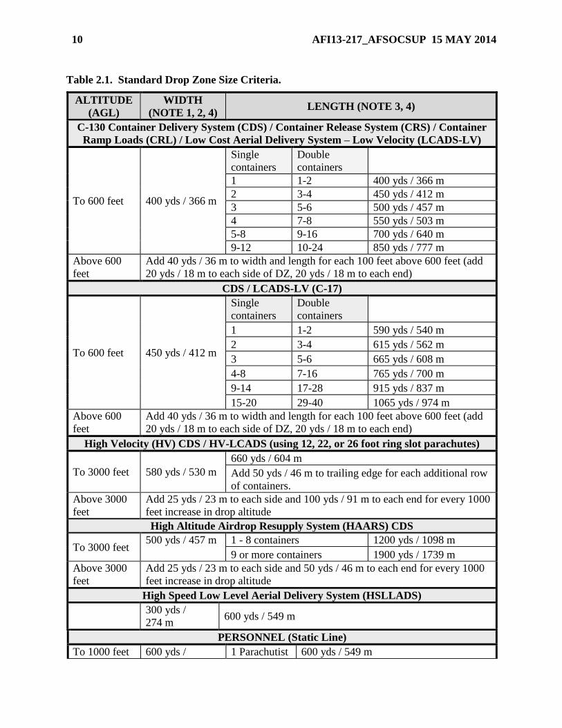
Table 2.1. Standard Drop Zone Size Criteria.
ALTITUDE
(AGL)
WIDTH
(NOTE 1, 2, 4) LENGTH (NOTE 3, 4)
C-130 Container Delivery System (CDS) / Container Release System (CRS) / Container
Ramp Loads (CRL) / Low Cost Aerial Delivery System – Low Velocity (LCADS-LV)
To 600 feet 400 yds / 366 m
Single
containers
Double
containers
1 1-2 400 yds / 366 m
2 3-4 450 yds / 412 m
3 5-6 500 yds / 457 m
4 7-8 550 yds / 503 m
5-8 9-16 700 yds / 640 m
9-12 10-24 850 yds / 777 m
Above 600
feet
Add 40 yds / 36 m to width and length for each 100 feet above 600 feet (add
20 yds / 18 m to each side of DZ, 20 yds / 18 m to each end)
CDS / LCADS-LV (C-17)
To 600 feet 450 yds / 412 m
Single
containers
Double
containers
1 1-2 590 yds / 540 m
2 3-4 615 yds / 562 m
3 5-6 665 yds / 608 m
4-8 7-16 765 yds / 700 m
9-14 17-28 915 yds / 837 m
15-20 29-40 1065 yds / 974 m
Above 600
feet
Add 40 yds / 36 m to width and length for each 100 feet above 600 feet (add
20 yds / 18 m to each side of DZ, 20 yds / 18 m to each end)
High Velocity (HV) CDS / HV-LCADS (using 12, 22, or 26 foot ring slot parachutes)
To 3000 feet 580 yds / 530 m
660 yds / 604 m
Add 50 yds / 46 m to trailing edge for each additional row
of containers.
Above 3000
feet
Add 25 yds / 23 m to each side and 100 yds / 91 m to each end for every 1000
feet increase in drop altitude
High Altitude Airdrop Resupply System (HAARS) CDS
To 3000 feet 500 yds / 457 m 1 - 8 containers 1200 yds / 1098 m
9 or more containers 1900 yds / 1739 m
Above 3000
feet
Add 25 yds / 23 m to each side and 50 yds / 46 m to each end for every 1000
feet increase in drop altitude
High Speed Low Level Aerial Delivery System (HSLLADS)
300 yds /
274 m 600 yds / 549 m
PERSONNEL (Static Line)
To 1000 feet 600 yds / 1 Parachutist 600 yds / 549 m
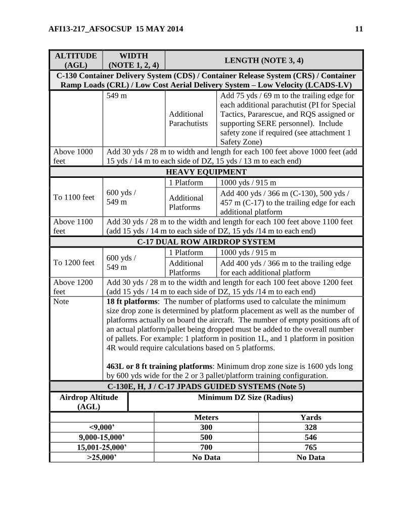
AFI13-217_AFSOCSUP 15 MAY 2014 11
ALTITUDE
(AGL)
WIDTH
(NOTE 1, 2, 4) LENGTH (NOTE 3, 4)
C-130 Container Delivery System (CDS) / Container Release System (CRS) / Container
Ramp Loads (CRL) / Low Cost Aerial Delivery System – Low Velocity (LCADS-LV)
549 m
Additional
Parachutists
Add 75 yds / 69 m to the trailing edge for
each additional parachutist (PI for Special
Tactics, Pararescue, and RQS assigned or
supporting SERE personnel). Include
safety zone if required (see attachment 1
Safety Zone)
Above 1000
feet
Add 30 yds / 28 m to width and length for each 100 feet above 1000 feet (add
15 yds / 14 m to each side of DZ, 15 yds / 13 m to each end)
HEAVY EQUIPMENT
To 1100 feet 600 yds /
549 m
1 Platform 1000 yds / 915 m
Additional
Platforms
Add 400 yds / 366 m (C-130), 500 yds /
457 m (C-17) to the trailing edge for each
additional platform
Above 1100
feet
Add 30 yds / 28 m to the width and length for each 100 feet above 1100 feet
(add 15 yds / 14 m to each side of DZ, 15 yds /14 m to each end)
C-17 DUAL ROW AIRDROP SYSTEM
To 1200 feet 600 yds /
549 m
1 Platform 1000 yds / 915 m
Additional
Platforms
Add 400 yds / 366 m to the trailing edge
for each additional platform
Above 1200
feet
Add 30 yds / 28 m to the width and length for each 100 feet above 1200 feet
(add 15 yds / 14 m to each side of DZ, 15 yds /14 m to each end)
Note 18 ft platforms: The number of platforms used to calculate the minimum
size drop zone is determined by platform placement as well as the number of
platforms actually on board the aircraft. The number of empty positions aft of
an actual platform/pallet being dropped must be added to the overall number
of pallets. For example: 1 platform in position 1L, and 1 platform in position
4R would require calculations based on 5 platforms.
463L or 8 ft training platforms: Minimum drop zone size is 1600 yds long
by 600 yds wide for the 2 or 3 pallet/platform training configuration.
C-130E, H, J / C-17 JPADS GUIDED SYSTEMS (Note 5)
Airdrop Altitude
(AGL)
Minimum DZ Size (Radius)
Meters Yards
<9,000’ 300 328
9,000-15,000’ 500 546
15,001-25,000’ 700 765
>25,000’ No Data No Data
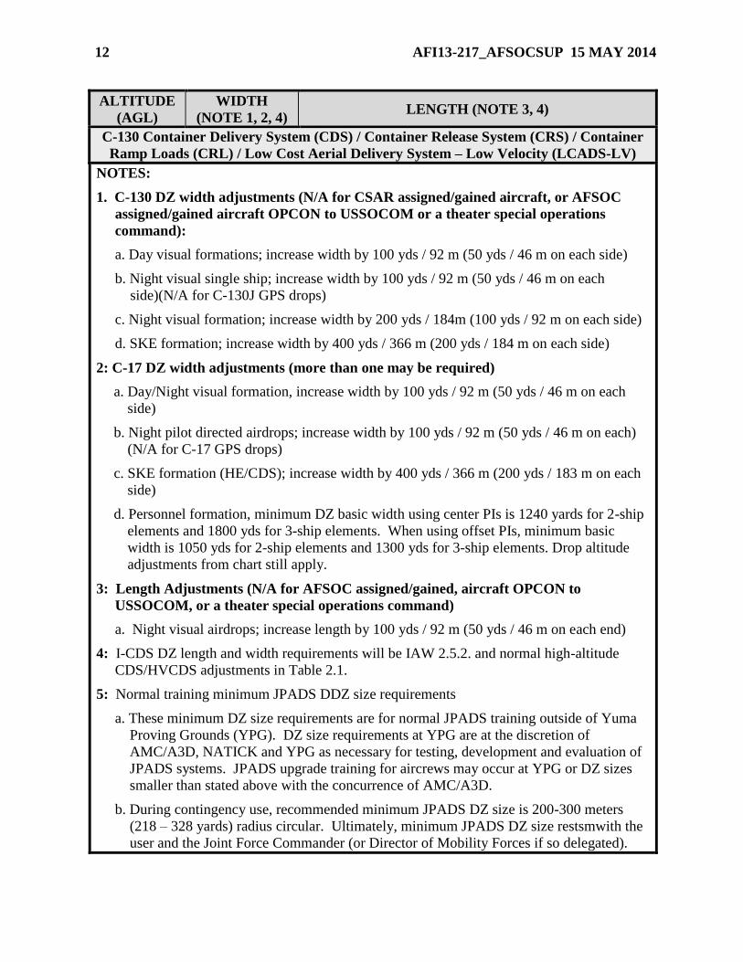
12 AFI13-217_AFSOCSUP 15 MAY 2014
ALTITUDE
(AGL)
WIDTH
(NOTE 1, 2, 4) LENGTH (NOTE 3, 4)
C-130 Container Delivery System (CDS) / Container Release System (CRS) / Container
Ramp Loads (CRL) / Low Cost Aerial Delivery System – Low Velocity (LCADS-LV)
NOTES:
1. C-130 DZ width adjustments (N/A for CSAR assigned/gained aircraft, or AFSOC
assigned/gained aircraft OPCON to USSOCOM or a theater special operations
command):
a. Day visual formations; increase width by 100 yds / 92 m (50 yds / 46 m on each side)
b. Night visual single ship; increase width by 100 yds / 92 m (50 yds / 46 m on each
side)(N/A for C-130J GPS drops)
c. Night visual formation; increase width by 200 yds / 184m (100 yds / 92 m on each side)
d. SKE formation; increase width by 400 yds / 366 m (200 yds / 184 m on each side)
2: C-17 DZ width adjustments (more than one may be required)
a. Day/Night visual formation, increase width by 100 yds / 92 m (50 yds / 46 m on each
side)
b. Night pilot directed airdrops; increase width by 100 yds / 92 m (50 yds / 46 m on each)
(N/A for C-17 GPS drops)
c. SKE formation (HE/CDS); increase width by 400 yds / 366 m (200 yds / 183 m on each
side)
d. Personnel formation, minimum DZ basic width using center PIs is 1240 yards for 2-ship
elements and 1800 yds for 3-ship elements. When using offset PIs, minimum basic
width is 1050 yds for 2-ship elements and 1300 yds for 3-ship elements. Drop altitude
adjustments from chart still apply.
3: Length Adjustments (N/A for AFSOC assigned/gained, aircraft OPCON to
USSOCOM, or a theater special operations command)
a. Night visual airdrops; increase length by 100 yds / 92 m (50 yds / 46 m on each end)
4: I-CDS DZ length and width requirements will be IAW 2.5.2. and normal high-altitude
CDS/HVCDS adjustments in Table 2.1.
5: Normal training minimum JPADS DDZ size requirements
a. These minimum DZ size requirements are for normal JPADS training outside of Yuma
Proving Grounds (YPG). DZ size requirements at YPG are at the discretion of
AMC/A3D, NATICK and YPG as necessary for testing, development and evaluation of
JPADS systems. JPADS upgrade training for aircrews may occur at YPG or DZ sizes
smaller than stated above with the concurrence of AMC/A3D.
b. During contingency use, recommended minimum JPADS DZ size is 200-300 meters
(218 – 328 yards) radius circular. Ultimately, minimum JPADS DZ size restsmwith the
user and the Joint Force Commander (or Director of Mobility Forces if so delegated).
AFI13-217_AFSOCSUP 15 MAY 2014 13
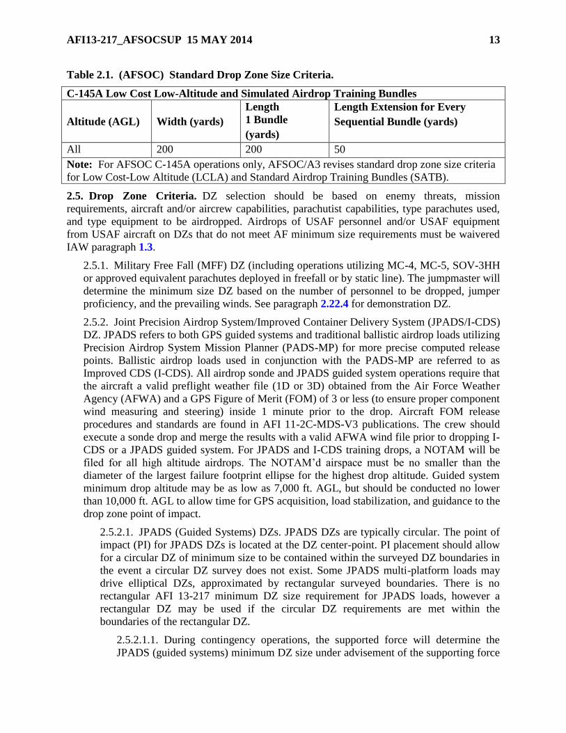
Table 2.1. (AFSOC) Standard Drop Zone Size Criteria.
C-145A Low Cost Low-Altitude and Simulated Airdrop Training Bundles
Altitude (AGL) Width (yards)
Length
1 Bundle
(yards)
Length Extension for Every
Sequential Bundle (yards)
All 200 200 50
Note: For AFSOC C-145A operations only, AFSOC/A3 revises standard drop zone size criteria
for Low Cost-Low Altitude (LCLA) and Standard Airdrop Training Bundles (SATB).
2.5. Drop Zone Criteria. DZ selection should be based on enemy threats, mission
requirements, aircraft and/or aircrew capabilities, parachutist capabilities, type parachutes used,
and type equipment to be airdropped. Airdrops of USAF personnel and/or USAF equipment
from USAF aircraft on DZs that do not meet AF minimum size requirements must be waivered
IAW paragraph 1.3.
2.5.1. Military Free Fall (MFF) DZ (including operations utilizing MC-4, MC-5, SOV-3HH
or approved equivalent parachutes deployed in freefall or by static line). The jumpmaster will
determine the minimum size DZ based on the number of personnel to be dropped, jumper
proficiency, and the prevailing winds. See paragraph 2.22.4 for demonstration DZ.
2.5.2. Joint Precision Airdrop System/Improved Container Delivery System (JPADS/I-CDS)
DZ. JPADS refers to both GPS guided systems and traditional ballistic airdrop loads utilizing
Precision Airdrop System Mission Planner (PADS-MP) for more precise computed release
points. Ballistic airdrop loads used in conjunction with the PADS-MP are referred to as
Improved CDS (I-CDS). All airdrop sonde and JPADS guided system operations require that
the aircraft a valid preflight weather file (1D or 3D) obtained from the Air Force Weather
Agency (AFWA) and a GPS Figure of Merit (FOM) of 3 or less (to ensure proper component
wind measuring and steering) inside 1 minute prior to the drop. Aircraft FOM release
procedures and standards are found in AFI 11-2C-MDS-V3 publications. The crew should
execute a sonde drop and merge the results with a valid AFWA wind file prior to dropping I-
CDS or a JPADS guided system. For JPADS and I-CDS training drops, a NOTAM will be
filed for all high altitude airdrops. The NOTAM’d airspace must be no smaller than the
diameter of the largest failure footprint ellipse for the highest drop altitude. Guided system
minimum drop altitude may be as low as 7,000 ft. AGL, but should be conducted no lower
than 10,000 ft. AGL to allow time for GPS acquisition, load stabilization, and guidance to the
drop zone point of impact.
2.5.2.1. JPADS (Guided Systems) DZs. JPADS DZs are typically circular. The point of
impact (PI) for JPADS DZs is located at the DZ center-point. PI placement should allow
for a circular DZ of minimum size to be contained within the surveyed DZ boundaries in
the event a circular DZ survey does not exist. Some JPADS multi-platform loads may
drive elliptical DZs, approximated by rectangular surveyed boundaries. There is no
rectangular AFI 13-217 minimum DZ size requirement for JPADS loads, however a
rectangular DZ may be used if the circular DZ requirements are met within the
boundaries of the rectangular DZ.
2.5.2.1.1. During contingency operations, the supported force will determine the
JPADS (guided systems) minimum DZ size under advisement of the supporting force
14 AFI13-217_AFSOCSUP 15 MAY 2014
aircrew using Table 2.1 Note 5.b. as a starting reference. During contingency
operations, a JPADS DZ and Launch Acceptability Region should be located within a
Restricted Operating Zone (ROZ). JPADS DZs will be selected to guarantee that all
bundles land within its confines to the maximum extent possible.
2.5.2.1.2. During training operations, GPS guided system drops are limited to DZs
resident in restricted areas and airspace. The aircrew/supporting force must ensure
through a collateral damage assessment IAW 2.5.2.4, that the load will impact the DZ
or non-populated/built-up area within the restricted area in the event of a chute or
guidance system malfunction. To ensure all loads land within the restricted airspace,
success and failure footprints generated by the PADS-MP will be located within the
restricted area. In addition to the guidance in paragraph 2.5.2, during training
missions, guided systems will only be dropped when the aircraft is within the 70
percent Launch Acceptable Region (LAR), the Airborne Guidance Unit (ABU) has a
valid GPS lock, and the aircraft is at or above the system specific minimum release
altitude.
2.5.2.1.2. (AFSOC) JPADS training airdrops for which success and failure
footprints fall outside of the lateral and vertical limits of a restricted area require an
AFSOC/A3 waiver. (T-2)
2.5.2.2. I-CDS. I-CDS DZs are typically normal rectangular CDS/HVCDS DZs IAW
Table 2.1. However, unlike traditional CDS, I-CDS provides the ability to “target” a
specific bundle for PI impact. For circular DZs, it may be appropriate to target the middle
bundle in a stick. If targeting the first bundle, follow standard PI placement criteria in
Table 2.2. For all I-CDS airdrop, independent of the targeted bundle, ensure that the 63%
ellipse is entirely contained within the surveyed DZ boundaries.
2.5.2.2.1. During contingency operations, I-CDS minimum DZ size is at the
discretion of the supported force and the JFC. The user will accept responsibility for
damage to structures, persons and equipment located on the surveyed DZ or the
Table 2.1 minimum sized DZ, whichever is greater, as a result of the airdrop.
2.5.2.2.2. During training operations, I-CDS airdrop operations DO NOT have to be
within a restricted area. For high-altitude airdrop operations, a restricted area is highly
recommended. Normal high-altitude CDS/HVCDS minimum DZ requirements in
Table 2.1 will be used.
2.5.2.3. Drop sondes. Drop sondes do not have a minimum DZ size and are deliberately
manually released from the aircraft. During contingency operations, drop sondes may be
released anywhere in the vicinity of the objective area and do not have to land on the DZ.
If not dropping on a surveyed DZ, the aircrew must coordinate with the Air Mobility
Division Tactics personnel to ensure the sonde will not cause injury to personnel or
damage to facilities. During training operations, drop sonde release must be incorporated
into the collateral damage assessment to ensure that the sonde will land on the DZ or
within a restricted area.
2.5.2.4. JPADS/I-CDS Collateral Damage Assessments. Collateral Damage Assessments
(CDA) are required for all JPADS (guided systems) and I-CDS airdrop operations. CDAs
are a necessary safety measure to mitigate as much damage risk as possible to aircraft,
AFI13-217_AFSOCSUP 15 MAY 2014 15
people, buildings and equipment on the DZ and surrounding areas. The CDA must be
accomplished for areas surrounding the DZ out to the furthest potential failure footprint
points created by the PADS-MP with a valid AFWA wind file. The CDA must include a
review of:
63% I-CDS success ellipse
Load malfunctions (fouled chute, broken guide lines, separated chute) that prevent
I-CDS loads from falling according to published ballistic data
Loss of GPS link on a guided load (3:1 glide ratio from drop altitude)
Load malfunction (fouled chute, broken guide lines, etc) that prevents guided
loads from navigating to the DZ
2.5.2.4.1. During contingency operations, the surveying or controlling unit, the user
and the JFC designated agency must accomplish a CDA. The user/supported force
ultimately accepts responsibility for all damage to structures, persons and equipment
as a result of the airdrop.
2.5.2.4.2. During normal training, coordinate with the owning agency of the special
use airspace and landowners (as necessary) with property surrounding the DZ for all
JPADS/I-CDS operations. Examine the area in the vicinity of the DZ for potential
damage in the course of normal operations or during extraordinary system failure
events. CDA coordination with the owning agency(s) of the DZ, airspace and
underlying ground space, must be accomplished prior to a DZ being approved for
JPADS guided systems.
2.5.2.4.3. Mission planners and aircrew must update the JPADS DZ CDA with the
owning agency(s) for changes prior to each drop operation. If the CDA demonstrates
potential airdrop load damage , restrict airdrop release (LAR), change drop altitude
(lower), change airdrop run-in, change parachute/system type, accept the risk or
cancel operations. Inform the controlling unit of the risk to their operations. The
controlling unit, and the JFC designated agency are approving authorities for risk to
the area surrounding the DZ. Intelligence personnel are responsible for providing the
JFC-designated agency close-up and overview imagery to facilitate CDAs.
2.5.3. Random Approach DZ. A random approach DZ is a variation of a previously surveyed
DZ and of sufficient size to permit multiple run-in headings. Any axis of approach may be
used as long as the resulting DZ meets the minimum criteria for the load/personnel being
airdropped and remains within the boundaries of the original surveyed DZ (see Table 2.1 and
Figure 2.1). In all cases, perform a safety-of-flight review IAW paragraph 2.22.1.2 prior to
use.
2.5.3.1. (Added-AFSOC) For personnel MFF operations, unit or mission commanders
may permit the use of random approach DZ procedures on current DZs, except when
specifically prohibited by the DZ survey or local procedures. Aircrews will thoroughly
review the airspace, terrain, obstacles, etc. surrounding the DZ prior to conducting MFF
operations using random approach DZ procedures. (T-2)
16 AFI13-217_AFSOCSUP 15 MAY 2014
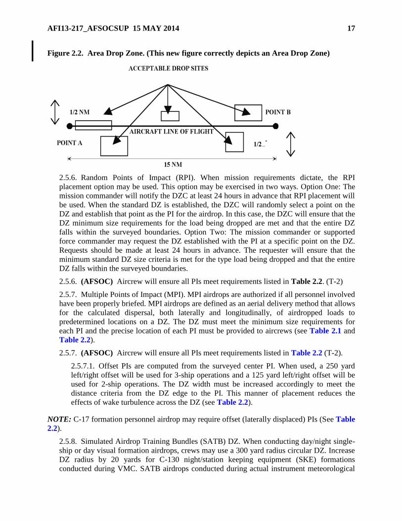
2.5.4. Area DZ. An area DZ (Figure 2.2) consists of a start point (point A), an endpoint
(point B), and a pre-arranged flight path (line-of-flight) over a series of acceptable drop sites
between these points. The distance between points A and B generally should not exceed 15
nautical miles and changes in ground elevation within NM of centerline should not exceed
300 feet. The reception committee may receive the drop at any location between point A and
point B within NM of center-line. Once the pre-briefed signal or electronic NAVAID has
been identified and located, the drop may be accomplished.
NOTE: Area DZs are not applicable to C-17 operations except SOLL II qualified crews.
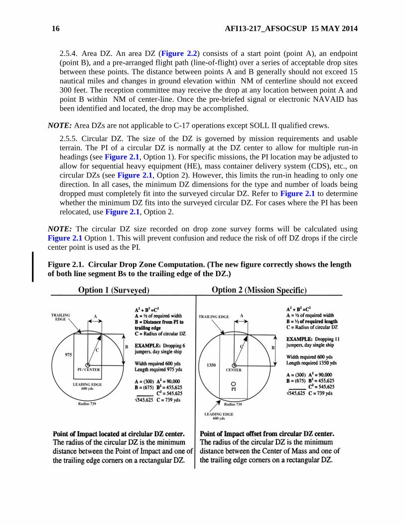
2.5.5. Circular DZ. The size of the DZ is governed by mission requirements and usable
terrain. The PI of a circular DZ is normally at the DZ center to allow for multiple run-in
headings (see Figure 2.1, Option 1). For specific missions, the PI location may be adjusted to
allow for sequential heavy equipment (HE), mass container delivery system (CDS), etc., on
circular DZs (see Figure 2.1, Option 2). However, this limits the run-in heading to only one
direction. In all cases, the minimum DZ dimensions for the type and number of loads being
dropped must completely fit into the surveyed circular DZ. Refer to Figure 2.1 to determine
whether the minimum DZ fits into the surveyed circular DZ. For cases where the PI has been
relocated, use Figure 2.1, Option 2.
NOTE: The circular DZ size recorded on drop zone survey forms will be calculated using
Figure 2.1 Option 1. This will prevent confusion and reduce the risk of off DZ drops if the circle
center point is used as the PI.
Figure 2.1. Circular Drop Zone Computation. (The new figure correctly shows the length
of both line segment Bs to the trailing edge of the DZ.)
AFI13-217_AFSOCSUP 15 MAY 2014 17
Figure 2.2. Area Drop Zone. (This new figure correctly depicts an Area Drop Zone)
2.5.6. Random Points of Impact (RPI). When mission requirements dictate, the RPI
placement option may be used. This option may be exercised in two ways. Option One: The
mission commander will notify the DZC at least 24 hours in advance that RPI placement will
be used. When the standard DZ is established, the DZC will randomly select a point on the
DZ and establish that point as the PI for the airdrop. In this case, the DZC will ensure that the
DZ minimum size requirements for the load being dropped are met and that the entire DZ
falls within the surveyed boundaries. Option Two: The mission commander or supported
force commander may request the DZ established with the PI at a specific point on the DZ.
Requests should be made at least 24 hours in advance. The requester will ensure that the
minimum standard DZ size criteria is met for the type load being dropped and that the entire
DZ falls within the surveyed boundaries.
2.5.6. (AFSOC) Aircrew will ensure all PIs meet requirements listed in Table 2.2. (T-2)
2.5.7. Multiple Points of Impact (MPI). MPI airdrops are authorized if all personnel involved
have been properly briefed. MPI airdrops are defined as an aerial delivery method that allows
for the calculated dispersal, both laterally and longitudinally, of airdropped loads to
predetermined locations on a DZ. The DZ must meet the minimum size requirements for
each PI and the precise location of each PI must be provided to aircrews (see Table 2.1 and
Table 2.2).
2.5.7. (AFSOC) Aircrew will ensure all PIs meet requirements listed in Table 2.2 (T-2).
2.5.7.1. Offset PIs are computed from the surveyed center PI. When used, a 250 yard
left/right offset will be used for 3-ship operations and a 125 yard left/right offset will be
used for 2-ship operations. The DZ width must be increased accordingly to meet the
distance criteria from the DZ edge to the PI. This manner of placement reduces the
effects of wake turbulence across the DZ (see Table 2.2).
NOTE: C-17 formation personnel airdrop may require offset (laterally displaced) PIs (See Table
2.2).
2.5.8. Simulated Airdrop Training Bundles (SATB) DZ. When conducting day/night single-
ship or day visual formation airdrops, crews may use a 300 yard radius circular DZ. Increase
DZ radius by 20 yards for C-130 night/station keeping equipment (SKE) formations
conducted during VMC. SATB airdrops conducted during actual instrument meteorological
18 AFI13-217_AFSOCSUP 15 MAY 2014
(IMC) conditions must follow the standard DZ size criteria for the type SATB airdrop being
conducted. To facilitate training, SATB airdrops conducted on military
reservations/restricted areas can use standard CDS DZ size criteria.
2.5.8. (AFSOC) See Table 2.1 Note.
2.5.9. Water DZ Criteria. Water DZs are normally circular and should meet the minimum
size criteria listed in Table 2.1 and Figure 2.1. Additional restrictions are at the discretion of
the using unit.
2.5.9.1. DZ water depth must be a minimum of 10 feet and the area must be free of
underwater obstructions to that depth.
2.5.9.2. Surface must be free of floating debris or moored craft. There should be no
protruding boulders, stumps, pilings or other hazards within 400 meters of the center of
the DZ.
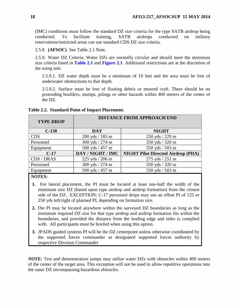
Table 2.2. Standard Point of Impact Placement.
TYPE DROP DISTANCE FROM APPROACH END
C-130 DAY NIGHT
CDS 200 yds / 183 m 250 yds / 229 m
Personnel 300 yds / 274 m 350 yds / 320 m
Equipment 500 yds / 457 m 550 yds / 503 m
C-17 DAY / NIGHT / IMC NIGHT Pilot Directed Airdrop (PDA)
CDS / DRAS 225 yds / 206 m 275 yds / 251 m
Personnel 300 yds / 274 m 350 yds / 320 m
Equipment 500 yds / 457 m 550 yds / 503 m
NOTES:
1. For lateral placement, the PI must be located at least one-half the width of the
minimum size DZ (based upon type airdrop and airdrop formation) from the closest
side of the DZ. EXCEPTION: C-17 personnel drops may use an offset PI of 125 or
250 yds left/right of planned PI, depending on formation size.
2. The PI may be located anywhere within the surveyed DZ boundaries as long as the
minimum required DZ size for that type airdrop and airdrop formation fits within the
boundaries, and provided the distance from the leading edge and sides is complied
with. All participants must be briefed when using this option.
3. JPADS guided systems PI will be the DZ centerpoint unless otherwise coordinated by
the supported forces commander as designated supported forces authority by
respective Division Commander
NOTE: Test and demonstration jumps may utilize water DZs with obstacles within 400 meters
of the center of the target area. This exception will not be used to allow repetitive operations into
the same DZ encompassing hazardous obstacles.
AFI13-217_AFSOCSUP 15 MAY 2014 19
2.5.9.3. The DZ should not be located near swift currents. For personnel drops, the
current should not exceed 2 knots. When current speed measuring equipment is not
available, and oceanographic/ tidal charts depict currents in excess of 2 knots, a waiver is
required prior to the drop IAW paragraph 1.3.
2.5.9.4. For training, sea state limits are based on the ability of recovery assets to quickly
locate and recover jumpers and their equipment. For contingencies, sea state limits are at
the discretion of the jumpmaster. See Attachment 2 for wind/sea state observation chart.
2.5.9.5. Unilateral training support requirements for water DZ operations - See AFI 11-
410.
2.5.9.6. Approved Flotation Devices. The following guidance applies to military free-fall
(MFF) and static line parachutists.
2.5.9.6.1. MFF. For day or night high altitude low opening (HALO)/high altitude
high opening (HAHO) operations, US Air Force parachutists will wear AF and/or
MAJCOM-approved flotation devices under these circumstances: when directed by
AFMAN 11-411(I); when the jumper's planned flight path (from exit to impact point)
is over a water obstacle for more than half the planned flight path distance; when a
water obstacle is within 1,000 meters of the impact point.
NOTE: A water obstacle is defined as any body of water that has a depth of four feet or more,
length and width of more than 40 feet.
2.5.9.6.1. (AFSOC) See AFMAN 11-411 (I) for additional guidance.
2.5.9.6.2. Static Line. USAF parachutists will wear AF and/or MAJCOM-approved
flotation devices when a water obstacle is within 1,000 meters of the intended jumper
dispersal pattern (CARP to DZ), or when directed by AFMAN 11-420(I).
2.5.9.6.2. (AFSOC) See AFMAN 11-420 (I) for additional guidance.
2.5.10. Tactical DZ. Tactical DZs are primarily used during exercises or contingencies. They
provide the supported forces commander with a means to rapidly respond to user requests
through the rapid survey/approval process. Tactical DZs are normally restricted to missions
supporting actual resupply and personnel infiltration airdrops (versus proficiency jumps,
SATBs, etc.). Tactical DZ surveys are done in an abbreviated manner, but still require a
physical survey of the DZ, by Special Tactics (ST) combat controllers, Air Mobility Liaison
Officer (AMLO), or the supported force, to ensure DZ suitability. A safety-of-flight review is
also required.
NOTE: If a tactical DZ survey is done to meet new run-in axis requirements on an existing
survey, then only a safety-of-flight review is required. Tactical DZ will not be used for routine or
repetitive training.
2.5.11. Special Purpose DZs. Special purpose DZs are only approved for use by AF special
tactics, combat rescue officers, pararescue, and RQS assigned or supporting SERE
Specialists. Training jumps should closely duplicate conditions that could be encountered
during operational missions, to include rough terrain, open sea and unfamiliar or unimproved
areas. Care will be taken to ensure that all conditions, especially safety-related are identified
to the JM and jumpers.
20 AFI13-217_AFSOCSUP 15 MAY 2014
2.5.11.1. Coordination for Use. The OG/CC, or designated representative, will
coordinate with agencies exercising control over sites selected for use and will publish
directives describing necessary operating instructions including hazards and restrictions.
Guidelines for selection and use are listed below:
2.5.11.1.1. Open Field DZ. Caution will be exercised with respect to terrain and
obstacles such as runways, lights, high tension lines, rocky terrain, etc., that could be
hazardous to jumpers. Hazards must not be located within 100 meters of the center of
the DZ (Exception: When conducting runway assault operations and demonstration
jumps).
2.5.11.1.2. Tree Jump DZ. The criteria for selecting open field jumps apply as well to
tree jump areas; in addition, they will be selected to be relatively free of stumps and
dead falls. Certain trees have hazardous features such as excessive height, sloping
branches, or no branches, and should be taken into account when selecting the DZ.
Complete tree jump equipment will be worn when conducting intentional tree jumps.
2.5.11.1.3. Mission DZs. The OG/CC, or designated representative, will periodically
select unimproved and unfamiliar jump areas for the purpose of conducting
operational mission training. Areas selected must meet the above criteria however;
shrub brush, thickets, small trees and tundra areas are not considered hazardous to
jumpers. Tree stumps that would be considered hazardous will not be located closer
than 50 meters from the center of the target. Risk management must be exercised by
the JM when conducting operational mission training and an extensive evaluation
should be performed prior to deployment.
2.5.11.1.4. Water DZs. Hazardous obstacles such as buoys, channel markers, piers,
and shoreline will be at least 400 meters from the center of the target area.
2.6. Instrument Meteorological Condition Airdrops. For U.S. Army training drops, a
minimum ceiling of 200 feet above ground level (AGL) is normally required. This may be
waived by the supported forces commander/user, but must be identified before the mission is
flown. Peacetime airdrops of actual personnel or equipment for unilateral training will not be
made when weather conditions over the DZ are less than a 300 foot ceiling and one-half mile
visibility. During operational missions, ceiling and visibility minimums are at the discretion of
the supported forces commander. For joint exercises, Air Force personnel are authorized to use
Army minimums. When the ceiling is less than 600 feet AGL, clear all personnel from the DZ
NLT 5 minutes prior to the scheduled airdrop time over target (TOT) and ensure they remain
clear until completion of the airdrop.
2.7. Aerial Power Line Restrictions. For the purpose of this publication, all restrictions apply
to aerial power lines operating at 50 volts or greater.
2.7.1. Power lines present a significant hazard to jumpers. Jumpers can sustain life
threatening injuries from electric shock and/or falls from a collapsed canopy.
2.7.2. To reduce this hazard, first attempt to site DZs so no power lines are located within
1000 meters of any DZ boundary.
2.7.3. If power lines are located within 1,000 meters of any boundary, coordinate with the
Power Company to shut off power NLT 15 minutes prior to TOT.
AFI13-217_AFSOCSUP 15 MAY 2014 21
2.7.4. If power cannot be interrupted, the flying mission commander, aircrew, and
jumpmaster must conduct a risk assessment of the mission. Include as a minimum; type
jump, jumper experience, aircrew experience, ceiling, and surface/altitude wind limits
required to approve, suspend, or cancel the operation. To further minimize risks, consider
altering the mission profile to raise/lower drop altitudes, change DZ run-in/escape headings,
or remove inexperienced jumpers from the stick. If possible, mark power lines with visual
markings (lights, smoke, or VS-17 panels).
WARNING: At no time will military personnel attempt to climb power line poles to position or
affix markings to wires or poles.
2.7.5. During USAF MFF operations, aircrews should ensure the Jumpmaster/Team leader is
aware when aerial power lines are within 1,000 meters of the intended PI.
2.7.6. Non-USAF personnel will comply with their service guidance for power line
procedures and restrictions.
2.8. Airdrop Winds. DZ wind information is critical to airdrop accuracy and is used by
aircrews to compute the adjusted release point. It is imperative that accurate and timely wind
data be transmitted to the aircrew. This includes not only surface wind and the computed mean
effective wind, but also any unusual observations (i.e., wind shear or local phenomena that could
affect wind direction, speed or restrictions to visibility).
2.8.1. Surface Wind. The surface wind at the DZ is normally measured using an anemometer
or other calibrated wind-measuring device. Wind direction is reported in magnetic degrees
and wind speed in knots. The direction reported is the direction the wind is coming from.
Surface wind limitations are listed in Table 2.3 and Table 2.4.
2.8.1. (AFSOC) When there are contradictions between AFI 13-217 and AFI 11-231,
Computed Air Release Point Procedures, wind limits, the AFI 13-217 wind limits tables will
take precedence. (T-2)
2.8.2. Mean Effective Wind. The mean effective wind (MEW) is a theoretical wind of
constant speed and direction that extends from the ground to a designated altitude. When
required, the DZC determines the MEW by timing the ascension of a helium-filled balloon to
a pre-determined altitude and measuring the angle of drift. The MEW is an indicator of the
drift line and distance an airdropped object can be expected to travel. Table 2.5 is used to
determine average wind speed from the surface to various drop altitudes.
22 AFI13-217_AFSOCSUP 15 MAY 2014
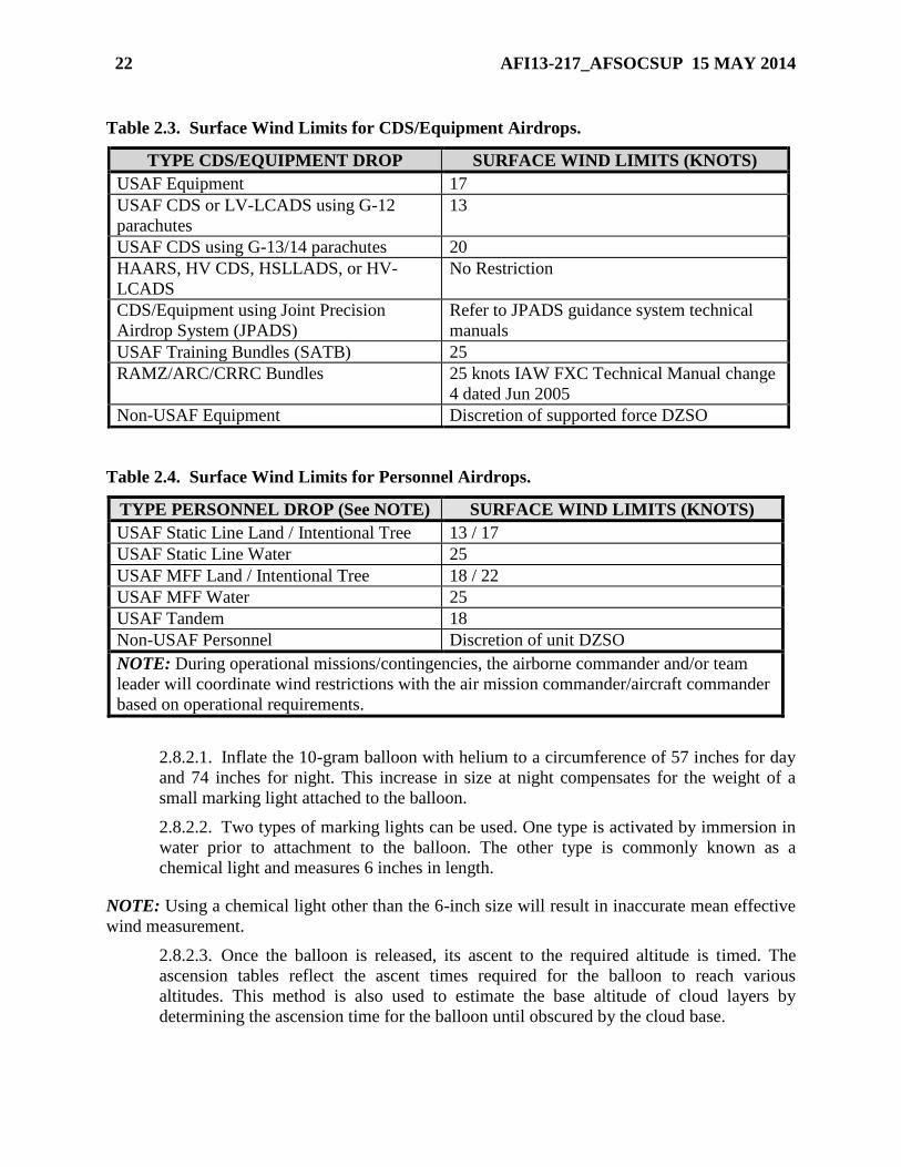
Table 2.3. Surface Wind Limits for CDS/Equipment Airdrops.
TYPE CDS/EQUIPMENT DROP SURFACE WIND LIMITS (KNOTS)
USAF Equipment 17
USAF CDS or LV-LCADS using G-12
parachutes
13
USAF CDS using G-13/14 parachutes 20
HAARS, HV CDS, HSLLADS, or HV-
LCADS
No Restriction
CDS/Equipment using Joint Precision
Airdrop System (JPADS)
Refer to JPADS guidance system technical
manuals
USAF Training Bundles (SATB) 25
RAMZ/ARC/CRRC Bundles 25 knots IAW FXC Technical Manual change
4 dated Jun 2005
Non-USAF Equipment Discretion of supported force DZSO
Table 2.4. Surface Wind Limits for Personnel Airdrops.
TYPE PERSONNEL DROP (See NOTE) SURFACE WIND LIMITS (KNOTS)
USAF Static Line Land / Intentional Tree 13 / 17
USAF Static Line Water 25
USAF MFF Land / Intentional Tree 18 / 22
USAF MFF Water 25
USAF Tandem 18
Non-USAF Personnel Discretion of unit DZSO
NOTE: During operational missions/contingencies, the airborne commander and/or team
leader will coordinate wind restrictions with the air mission commander/aircraft commander
based on operational requirements.
2.8.2.1. Inflate the 10-gram balloon with helium to a circumference of 57 inches for day
and 74 inches for night. This increase in size at night compensates for the weight of a
small marking light attached to the balloon.
2.8.2.2. Two types of marking lights can be used. One type is activated by immersion in
water prior to attachment to the balloon. The other type is commonly known as a
chemical light and measures 6 inches in length.
NOTE: Using a chemical light other than the 6-inch size will result in inaccurate mean effective
wind measurement.
2.8.2.3. Once the balloon is released, its ascent to the required altitude is timed. The
ascension tables reflect the ascent times required for the balloon to reach various
altitudes. This method is also used to estimate the base altitude of cloud layers by
determining the ascension time for the balloon until obscured by the cloud base.
AFI13-217_AFSOCSUP 15 MAY 2014 23
2.8.2.4. During ascent, unusual movement by the balloon is indicative of erratic wind
conditions and should be noted. The altitude of these occurrences, if significant, should
be included in the MEW report to the aircraft.
2.8.2.5. When the balloon reaches drop altitude the elevation angle is measured with a
pocket transit, theodolite, clinometer, or any other accurate means available.
2.8.2.6. The magnetic azimuth to the balloon is measured and the reciprocal heading
noted. This will give the MEW wind direction.
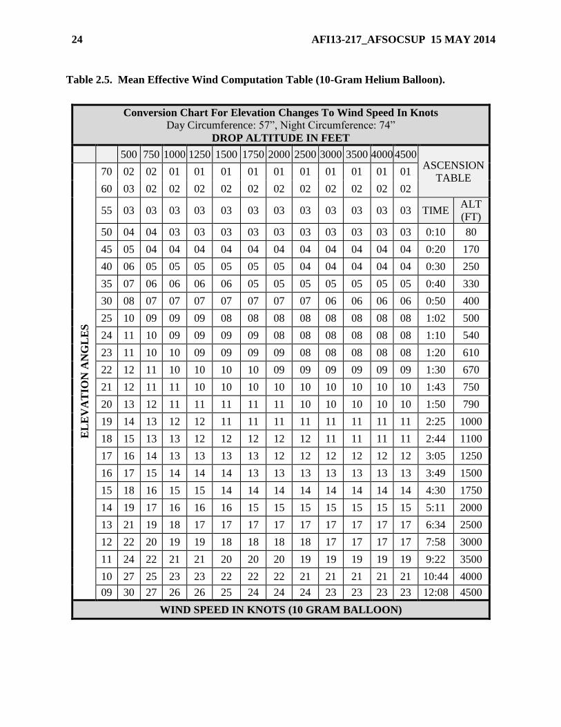
2.8.2.7. Referring to the scale on the left side of Table 2.5, locate the angle that
corresponds to the angle measured. Move horizontally across the table to the vertical
column that corresponds to the drop altitude being used. The value at the intersection of
these two lines is the MEW wind speed in knots.
2.8.2.8. When transmitting the MEW, make sure it is identified as the “mean effective
wind” and the altitude to which it was taken is included. Phraseology: “TALON ZERO
ONE, MEAN EFFECTIVE WIND AT (DROP ALTITUDE AGL), ESTIMATED
THREE FIVE ZERO AT ONE NINER.” Indication of erratic winds or wind shear should
be reported at that time.
2.8.3. Altitude Winds. There are no altitude wind restrictions for fixed wing airdrops. Refer
to the appropriate MDS-specific aircraft AFI for altitude wind restrictions for rotary wing
aircraft. If surface winds are not provided, altitude winds may influence the jumpmaster’s
decision to drop personnel.
24 AFI13-217_AFSOCSUP 15 MAY 2014
Table 2.5. Mean Effective Wind Computation Table (10-Gram Helium Balloon).
Conversion Chart For Elevation Changes To Wind Speed In Knots
Day Circumference: 57”, Night Circumference: 74”
DROP ALTITUDE IN FEET
500 750 1000 1250 1500 1750 2000 2500 3000 3500 4000 4500 ASCENSION
TABLE
EL
EV
AT
ION
AN
GL
ES
70 02 02 01 01 01 01 01 01 01 01 01 01
60 03 02 02 02 02 02 02 02 02 02 02 02
55 03 03 03 03 03 03 03 03 03 03 03 03 TIME ALT
(FT)
50 04 04 03 03 03 03 03 03 03 03 03 03 0:10 80
45 05 04 04 04 04 04 04 04 04 04 04 04 0:20 170
40 06 05 05 05 05 05 05 04 04 04 04 04 0:30 250
35 07 06 06 06 06 05 05 05 05 05 05 05 0:40 330
30 08 07 07 07 07 07 07 07 06 06 06 06 0:50 400
25 10 09 09 09 08 08 08 08 08 08 08 08 1:02 500
24 11 10 09 09 09 09 08 08 08 08 08 08 1:10 540
23 11 10 10 09 09 09 09 08 08 08 08 08 1:20 610
22 12 11 10 10 10 10 09 09 09 09 09 09 1:30 670
21 12 11 11 10 10 10 10 10 10 10 10 10 1:43 750
20 13 12 11 11 11 11 11 10 10 10 10 10 1:50 790
19 14 13 12 12 11 11 11 11 11 11 11 11 2:25 1000
18 15 13 13 12 12 12 12 12 11 11 11 11 2:44 1100
17 16 14 13 13 13 13 12 12 12 12 12 12 3:05 1250
16 17 15 14 14 14 13 13 13 13 13 13 13 3:49 1500
15 18 16 15 15 14 14 14 14 14 14 14 14 4:30 1750
14 19 17 16 16 16 15 15 15 15 15 15 15 5:11 2000
13 21 19 18 17 17 17 17 17 17 17 17 17 6:34 2500
12 22 20 19 19 18 18 18 18 17 17 17 17 7:58 3000
11 24 22 21 21 20 20 20 19 19 19 19 19 9:22 3500
10 27 25 23 23 22 22 22 21 21 21 21 21 10:44 4000
09 30 27 26 26 25 24 24 24 23 23 23 23 12:08 4500
WIND SPEED IN KNOTS (10 GRAM BALLOON)
AFI13-217_AFSOCSUP 15 MAY 2014 25
2.9. Drop Zone Markings. A marked DZ is defined as a DZ that has a PI or release point
marked with a pre-coordinated visual or electronic signal. Standard DZs may be marked with
raised angle markers (RAM), VS-17 marker panels, visible lighting systems, and light beacons.
Virtually any type of lighting or visual marking system is acceptable if all participating units are
briefed and concur. Night markings or visual acquisition aids may include a light gun, flares, fire
pots, railroad fuses, flashlights, chemlights, and infrared (IR) lighting systems. Electronic
NAVAID markings (ZM, SST-181, Tactical Aid to Navigation (TACAN), etc.) may be used for
either day or night operations and placed as directed by mission requirements.
NOTE: Ground parties and aircrews must coordinate and brief NO-DROP markings for all types of DZs.
For C-17 and C-130J operations, all Point-of-Impact (PI) coordinates, if different than planned,
must be relayed to the aircrew no later than 15 minutes prior to the TOT. If PI coordinates are
not relayed 15 minutes prior, aircrew will advise earliest TOT feasible for new coordinates.
2.10. Standard Drop Zone Markings (Not required for CSAR assigned/gained aircraft or
AFSOC assigned/gained aircraft OPCON to USSOCOM, or a theater special operations
command).
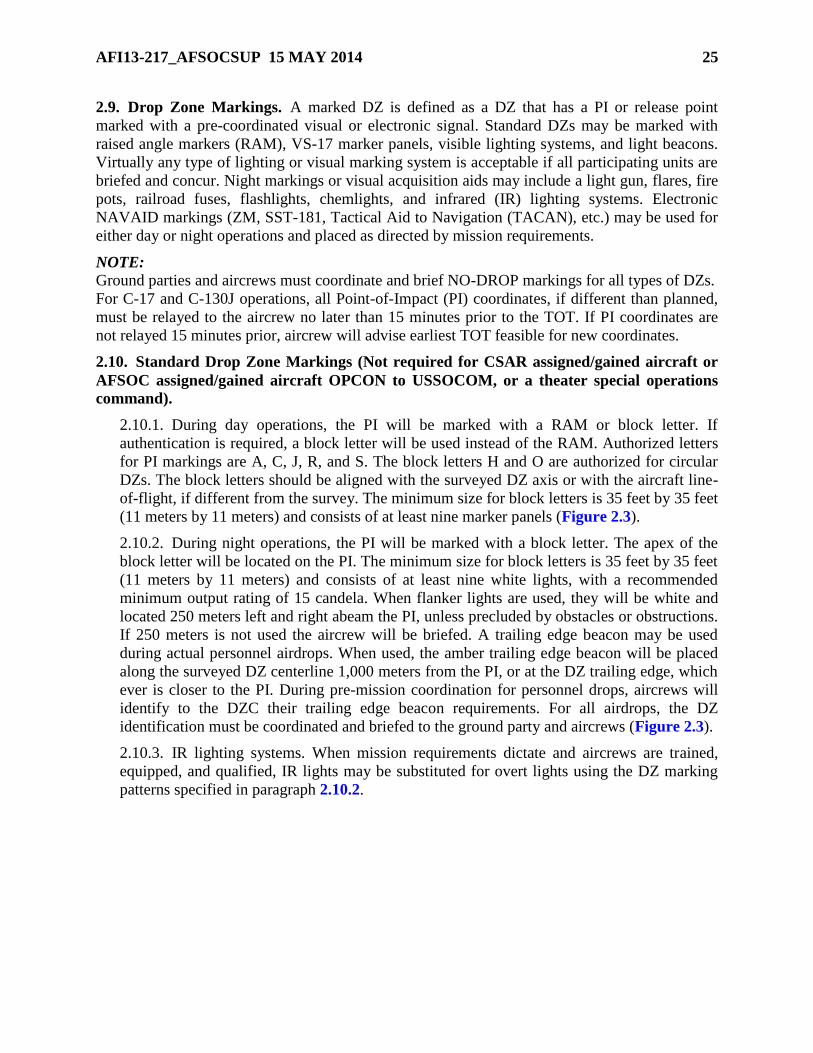
2.10.1. During day operations, the PI will be marked with a RAM or block letter. If
authentication is required, a block letter will be used instead of the RAM. Authorized letters
for PI markings are A, C, J, R, and S. The block letters H and O are authorized for circular
DZs. The block letters should be aligned with the surveyed DZ axis or with the aircraft line-
of-flight, if different from the survey. The minimum size for block letters is 35 feet by 35 feet
(11 meters by 11 meters) and consists of at least nine marker panels (Figure 2.3).
2.10.2. During night operations, the PI will be marked with a block letter. The apex of the
block letter will be located on the PI. The minimum size for block letters is 35 feet by 35 feet
(11 meters by 11 meters) and consists of at least nine white lights, with a recommended
minimum output rating of 15 candela. When flanker lights are used, they will be white and
located 250 meters left and right abeam the PI, unless precluded by obstacles or obstructions.
If 250 meters is not used the aircrew will be briefed. A trailing edge beacon may be used
during actual personnel airdrops. When used, the amber trailing edge beacon will be placed
along the surveyed DZ centerline 1,000 meters from the PI, or at the DZ trailing edge, which
ever is closer to the PI. During pre-mission coordination for personnel drops, aircrews will
identify to the DZC their trailing edge beacon requirements. For all airdrops, the DZ
identification must be coordinated and briefed to the ground party and aircrews (Figure 2.3).
2.10.3. IR lighting systems. When mission requirements dictate and aircrews are trained,
equipped, and qualified, IR lights may be substituted for overt lights using the DZ marking
patterns specified in paragraph 2.10.2.
26 AFI13-217_AFSOCSUP 15 MAY 2014
Figure 2.3. Standard Drop Zone Markings.
2.11. Non-Standard Drop Zone Markings
2.11.1. The tactical situation may dictate the use of nonstandard DZ markings. When
nonstandard markings or identification procedures are used, it is imperative that all
appropriate participants be thoroughly briefed.
2.11.2. Unmarked DZ. This type of DZ is not authenticated with any type of visual or
electronic marking. Unmarked DZs are normally used for contingency operations and may
not have a DZ party present. AF Special Tactics personnel, Combat Rescue officres,
Pararescue, RQS assigned or supporting SERE specialists, and USSOCOM assigned forces
are authorized to drop on unmarked DZs. During training missions, a DZC party must be on
site for safety.
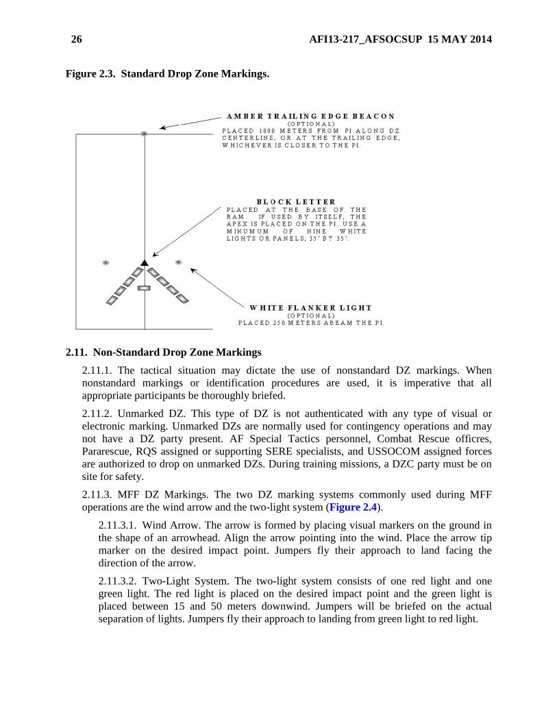
2.11.3. MFF DZ Markings. The two DZ marking systems commonly used during MFF
operations are the wind arrow and the two-light system (Figure 2.4).
2.11.3.1. Wind Arrow. The arrow is formed by placing visual markers on the ground in
the shape of an arrowhead. Align the arrow pointing into the wind. Place the arrow tip
marker on the desired impact point. Jumpers fly their approach to land facing the
direction of the arrow.
2.11.3.2. Two-Light System. The two-light system consists of one red light and one
green light. The red light is placed on the desired impact point and the green light is
placed between 15 and 50 meters downwind. Jumpers will be briefed on the actual
separation of lights. Jumpers fly their approach to landing from green light to red light.
AFI13-217_AFSOCSUP 15 MAY 2014 27
Figure 2.4. Military Free-Fall Drop Zone Markings.
2.11.4. Water DZ. Water drops can be conducted on marked or unmarked DZs. Marked DZs
will have mutually agreed upon markings (visual or electronic). Select markings that do not
mimic local maritime navigational aids (buoys, channel markers, etc.).
2.11.4.1. Marked Water DZ. GMRS, VIRS, CARP, or JMD (including moving target)
procedures may be used on marked DZ. For GMRS, the position of the recovery or safety
boat usually marks the intended release point. For water JMD drops, use moving target
procedures (Figure 2.5). Other options may be used to mark DZ; however, these
markings must be pre-briefed.
2.11.4.2. Unmarked Water DZ. Unmarked water DZs will have predetermined PIs.
Include coordinates of the PI in the aircrew, DZC and jumpmaster briefings.
2.11.5. Single Marked Multiple Points of Impact (MPI). Single marked MPI procedures are
authorized for Heavy Equipment/Container Delivery System (HE/CDS) airdrops where only
the first PI in a series of MPI is marked and all personnel involved have been properly
briefed. Single -marked MPI are restricted to along the DZ axis (no lateral displacement) and
to a maximum of 1500 yards between the first marked PI and the last unmarked PI. The DZ
must meet the minimum size requirements for each PI and the precise location of each PI
must be provided to aircrews (see Table 2.1 and Table 2.2).
28 AFI13-217_AFSOCSUP 15 MAY 2014
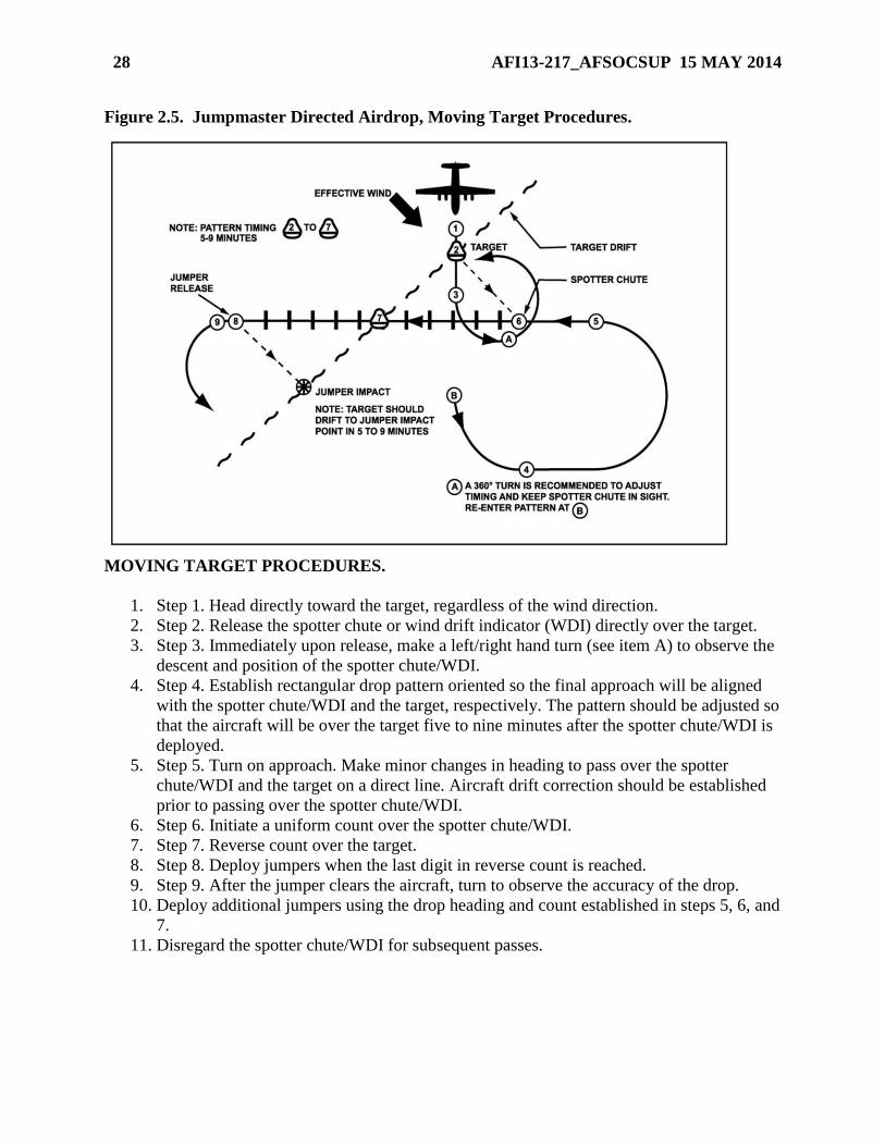
Figure 2.5. Jumpmaster Directed Airdrop, Moving Target Procedures.
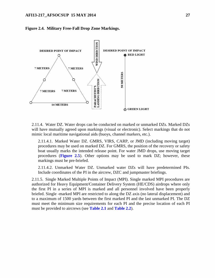
MOVING TARGET PROCEDURES.
1. Step 1. Head directly toward the target, regardless of the wind direction.
2. Step 2. Release the spotter chute or wind drift indicator (WDI) directly over the target.
3. Step 3. Immediately upon release, make a left/right hand turn (see item A) to observe the
descent and position of the spotter chute/WDI.
4. Step 4. Establish rectangular drop pattern oriented so the final approach will be aligned
with the spotter chute/WDI and the target, respectively. The pattern should be adjusted so
that the aircraft will be over the target five to nine minutes after the spotter chute/WDI is
deployed.
5. Step 5. Turn on approach. Make minor changes in heading to pass over the spotter
chute/WDI and the target on a direct line. Aircraft drift correction should be established
prior to passing over the spotter chute/WDI.
6. Step 6. Initiate a uniform count over the spotter chute/WDI.
7. Step 7. Reverse count over the target.
8. Step 8. Deploy jumpers when the last digit in reverse count is reached.
9. Step 9. After the jumper clears the aircraft, turn to observe the accuracy of the drop.
10. Deploy additional jumpers using the drop heading and count established in steps 5, 6, and
7.
11. Disregard the spotter chute/WDI for subsequent passes.
AFI13-217_AFSOCSUP 15 MAY 2014 29
Figure 2.5. Jumpmaster Directed Airdrop, Moving Target Procedures (continued).
1. When the target drift rate is changed (drogue chute is installed on target, no wind shift occurs,
etc.) the entire spotter chute/WDI procedure must be re-accomplished and a new drop heading
and count established starting with step 1.
MOVING TARGET PATTERN. Deployment procedures to a moving target are similar to
those employed for a stationary target. The moving target procedures takes into consideration
target drift and will place the team on the downdrift line of the moving target and not necessarily
on target. Special attention should be paid to the following items:
1. The pattern must be adjusted so that the initial pass over the target after spotter chute/WDI
deployment is not less than 5 minutes and not more than 9 minutes, 7 minutes being ideal. If the
initial pattern requires more than 9 minutes, the team will be too far downdrift/downwind and
with a high target drift rate may not be able to locate the target visually.
2. On the initial pass after the spotter chute/WDI deployment, an accurate count can be obtained
by the JM and the heading noted by both the JM and pilot. All subsequent passes will be made
on this initial heading using the count obtained on the first pass. No attempt should be made to
recheck the count or change the initial heading because the target will have drifted.
NOTE: On subsequent passes requiring a change of heading to place the aircraft over the target,
ensure the pilot corrects back to original heading. Moving target procedures are normally
conducted from fixed-wing aircraft.
2.12. Airdrop Communications. To the maximum extent possible, airdrop operations should
be planned to operate with minimum radio transmissions. In general, all missions are flown as
planned with additional radio calls made “by exception” only. Authentication is accomplished as
required. Detailed mission planning and pre-briefed operating procedures can eliminate many
flight-following and formation-only transmissions. Radio contact with the drop aircraft should be
limited to safety of flight requirements or issues affecting airborne force employment. This
includes ATC directions, range clearance, unsafe surface conditions or mission changes. DZ
winds or other information may be broadcast in the blind at a coordinated time prior to the
scheduled TOT.
2.12.1. Drop clearance to a marked DZ is normally inherent with mission clearance and is
confirmed by the aircrew observing the pre-briefed visual DZ markings. Unless radio
communications are specifically required, any coordinated markings, other than red smoke,
red flares, or red lights indicate a clearance to drop.
NOTE: During NVG operations colored flares may still be used, but due to the delay in aircrew
recognition of color, star clusters or other obvious signals are recommended.
2.12.2. Training airdrops (both unilateral and joint) conducted during IMC or to an
unmarked DZ require the DZC to relay drop clearance, (i.e., “Cleared to Drop”), to the
aircraft by way of radio communications or other pre-briefed method. Drop clearance is
usually accomplished a minimum of 2 minutes prior to the scheduled TOT.
30 AFI13-217_AFSOCSUP 15 MAY 2014
2.12.3. Mission clearance provides drop clearance on operational missions to DZs where no
reception party is present.
2.12.4. No-Drop Signals. A “NO-DROP” condition, closing of the DZ, or temporary closing
of the DZ will be indicated in one of the following ways: an authenticated radio transmission,
red smoke, red flares, red lights, scrambled panels, or another planned signal.
NOTE: During NVG operations colored flares may still be used, but due to the delay in aircrew
recognition of color, star clusters or other obvious signals are recommended.
2.12.4.1. A “NO-DROP” situation during IMC operations will be indicated by the
absence of pre-briefed electronic device(s), or an authenticated radio transmission.
2.12.4.2. Use standard no-drop signals to communicate temporary closing of a drop zone
or postponement of an airdrop. Aircrew should follow up with a radio call to the
appropriate C2 facility as the situation dictates.
2.12.5. When using radio communications, the following procedures apply:
2.12.5.1. “NO DROP” advisories should be transmitted early enough to allow time for
authentication; specifically, not later than 1 minute prior to actual TOT, unless an
emergency arises.
2.12.5.2. If last minute conditions preclude a safe drop and time for proper authentication
is not available, the DZC will immediately and repetitively transmit cancellation of drop
clearance, “NO-DROP, NO-DROP, NO-DROP.”
2.12.6. Authorized Relays:
2.12.6.1. Relay operational information to the aircraft as requested when abnormal
conditions necessitate such requests. DZCs should not be required to handle such
messages on a regular basis.
2.12.6.2. If necessary, inform the aircraft of the source of any messages being relayed
(DZSO, DZC, ground forces commander, etc.).
2.12.6.3. Transmitting the reason for an aircrew initiated “NO-DROP” is not normally
required. However, if time permits, the aircrew will pass the information to the DZC. For
a ground initiated “NO-DROP” (if time and security requirements permit) the DZC will
inform the aircrew of the reason and should coordinate any further action.
2.12.6.4. During airborne operations, the ground forces commander may need to
determine the number of personnel who did not jump (alibi jumpers) to properly account
for all personnel. When requested by the DZSO/DZ Support Team Leader (DZSTL), if
the tactical situation permits, the DZC obtains the total number of jumpers remaining on
board from the aircrew. This should not be accomplished until after the last aircraft over-
flies the DZ and at no time if it compromises safety or conflicts with aircrew or DZC
duties. Should such a conflict occur, delay or cancel transmissions accordingly.
2.12.7. Unauthorized Relays. Radio calls to determine order of flight, load information, and
administrative details are normally not authorized.
2.12.8. Only qualified DZ personnel will operate DZ communication equipment.
AFI13-217_AFSOCSUP 15 MAY 2014 31
2.13. Control Point Location. The DZC establishes the control point taking into account
pertinent factors such as an unobstructed line of sight, winds, positive control of the DZ,
surrounding airspace, and security requirements. Safety factors must always be considered when
choosing a control point location. During actual IMC, HV CDS or HAARS, locate the control
point off the DZ. The control point for multi-ship HE and all CDS equipment airdrops will be
offset a minimum of 300 yards (HE) and 200 yards (CDS) from the intended PI.
2.14. En Route and Terminal NAVAIDS. A variety of electronic NAVAIDS are available to
support drop zone operations including the TACAN, ZM, or radar beacons. These NAVAIDS
are utilized at the discretion of the JFACC, JFSOCC, or mission commander.
2.14.1. For airdrops, the normal placement for NAVAIDS is as follows:
2.14.1.1. The ZM (TPN-27) should be placed within 1,500 yards of the PI. For
maximum accuracy, the ZM should be as close to the PI as possible. If line-of-sight
considerations preclude placement of the ZM at the briefed location, relocate it and
advise the aircraft on initial contact of the new location relative to the PI. During night
airdrop operations, the ZM should be visually marked with a light to identify it as a
hazard to parachutists and to prevent accidental destruction of the ZM by vehicular
traffic.
2.14.1.2. Radar Beacon Operations. Special Tactics units maintain several different radar
beacon systems to include the SST 181, SMP 1000, and PPN-19. Pre-briefed/pre-
coordinated beacon use is required to ensure the proper beacon at the proper setting is
established.
2.14.1.2.1. For CARP airdrops, compute the wind drift distance for the load being
dropped and displace the beacons the computed distance and direction into the wind
from the PI.
2.14.1.2.1. (AFSOC) AFSOC may place the radar beacon at the PI when using both
the infrared (IR) strobe and beacon on the same DZ.
2.14.1.2.2. For high altitude airdrop operations, place radar beacons on the PI.
Aircrews and DZC must ensure that the PI coordinates are IAW Table 2.1 high
altitude minimum DZ size requirements. High altitude airdrop PI’s will be greater
than Table 2.2 standard point of impact placement after Table 2.1 minimum DZ size,
length and width adjustments are made.
2.14.1.2.3. For MFF airdrops, the beacons will be placed on the PI.
2.14.1.2.4. The TACAN should not be placed on a DZ as an airdrop aid.
2.15. Ground Marked Release System. When controlling an airdrop, the DZC can mark a
point on the ground with a visual signal to designate the computed Release Point (RP) to the
aircrew. This signal may be a four marker “L”, six marker “T”, or seven marker “H” and is
placed abeam, and 100 meters (110 yds) left of the desired release point as depicted in Figure
2.6. The drop is executed when the aircraft is directly abeam, and 100 meters (110 yds.) right of
this marker on the pre-briefed inbound heading. A pre-briefed code signal or beacon may be
collocated with the markers to aid in DZ identification.
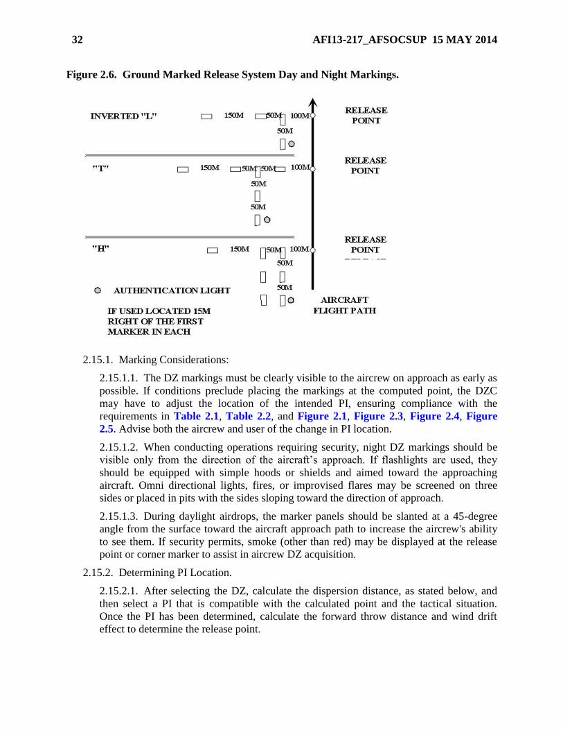
32 AFI13-217_AFSOCSUP 15 MAY 2014
Figure 2.6. Ground Marked Release System Day and Night Markings.
2.15.1. Marking Considerations:
2.15.1.1. The DZ markings must be clearly visible to the aircrew on approach as early as
possible. If conditions preclude placing the markings at the computed point, the DZC
may have to adjust the location of the intended PI, ensuring compliance with the
requirements in Table 2.1, Table 2.2, and Figure 2.1, Figure 2.3, Figure 2.4, Figure
2.5. Advise both the aircrew and user of the change in PI location.
2.15.1.2. When conducting operations requiring security, night DZ markings should be
visible only from the direction of the aircraft’s approach. If flashlights are used, they
should be equipped with simple hoods or shields and aimed toward the approaching
aircraft. Omni directional lights, fires, or improvised flares may be screened on three
sides or placed in pits with the sides sloping toward the direction of approach.
2.15.1.3. During daylight airdrops, the marker panels should be slanted at a 45-degree
angle from the surface toward the aircraft approach path to increase the aircrew's ability
to see them. If security permits, smoke (other than red) may be displayed at the release
point or corner marker to assist in aircrew DZ acquisition.
2.15.2. Determining PI Location.
2.15.2.1. After selecting the DZ, calculate the dispersion distance, as stated below, and
then select a PI that is compatible with the calculated point and the tactical situation.
Once the PI has been determined, calculate the forward throw distance and wind drift
effect to determine the release point.
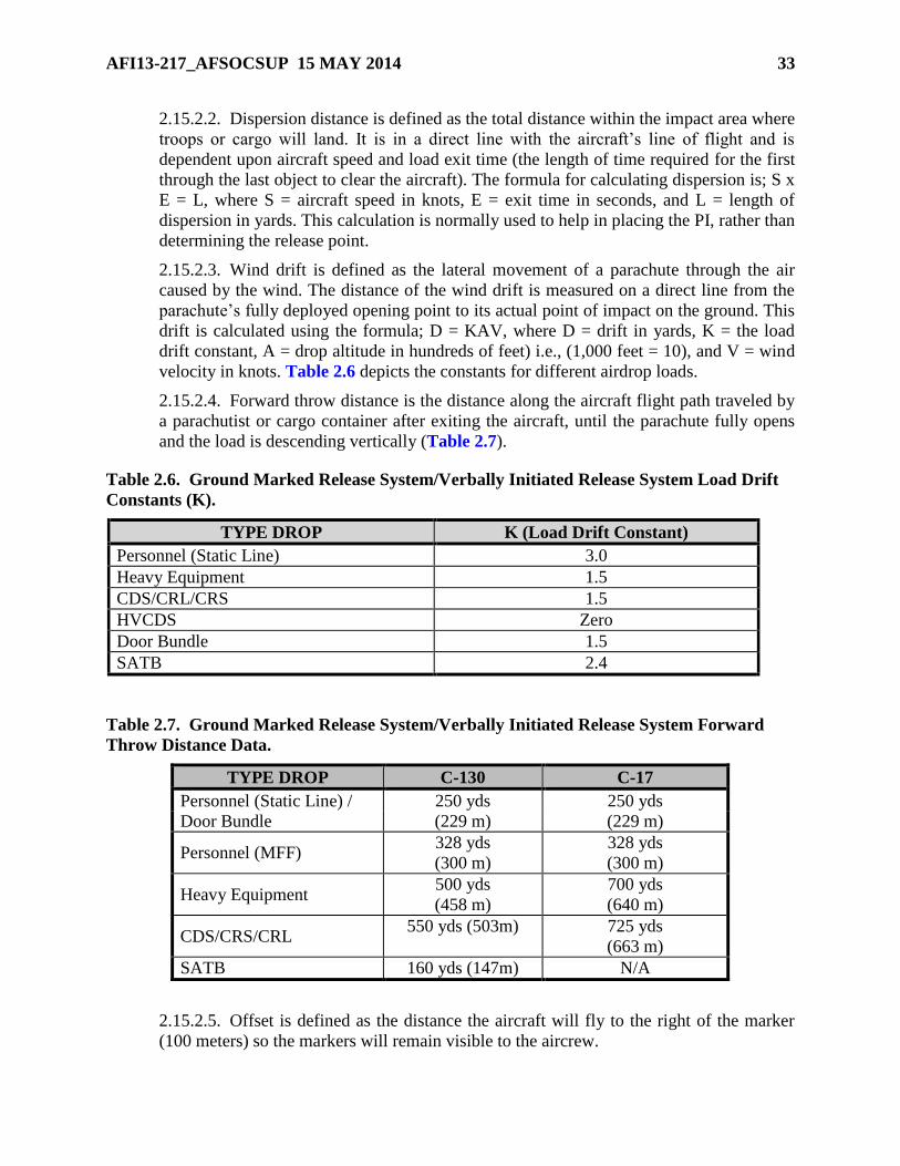
AFI13-217_AFSOCSUP 15 MAY 2014 33
2.15.2.2. Dispersion distance is defined as the total distance within the impact area where
troops or cargo will land. It is in a direct line with the aircraft’s line of flight and is
dependent upon aircraft speed and load exit time (the length of time required for the first
through the last object to clear the aircraft). The formula for calculating dispersion is; S x
E = L, where S = aircraft speed in knots, E = exit time in seconds, and L = length of
dispersion in yards. This calculation is normally used to help in placing the PI, rather than
determining the release point.
2.15.2.3. Wind drift is defined as the lateral movement of a parachute through the air
caused by the wind. The distance of the wind drift is measured on a direct line from the
parachute’s fully deployed opening point to its actual point of impact on the ground. This
drift is calculated using the formula; D = KAV, where D = drift in yards, K = the load
drift constant, A = drop altitude in hundreds of feet) i.e., (1,000 feet = 10), and V = wind
velocity in knots. Table 2.6 depicts the constants for different airdrop loads.
2.15.2.4. Forward throw distance is the distance along the aircraft flight path traveled by
a parachutist or cargo container after exiting the aircraft, until the parachute fully opens
and the load is descending vertically (Table 2.7).
Table 2.6. Ground Marked Release System/Verbally Initiated Release System Load Drift
Constants (K).
TYPE DROP K (Load Drift Constant)
Personnel (Static Line) 3.0
Heavy Equipment 1.5
CDS/CRL/CRS 1.5
HVCDS Zero
Door Bundle 1.5
SATB 2.4
Table 2.7. Ground Marked Release System/Verbally Initiated Release System Forward
Throw Distance Data.
TYPE DROP C-130 C-17
Personnel (Static Line) / 250 yds 250 yds
Door Bundle (229 m) (229 m)
Personnel (MFF) 328 yds
(300 m)
328 yds
(300 m)
Heavy Equipment 500 yds
(458 m)
700 yds
(640 m)
CDS/CRS/CRL 550 yds (503m) 725 yds
(663 m)
SATB 160 yds (147m) N/A
2.15.2.5. Offset is defined as the distance the aircraft will fly to the right of the marker
(100 meters) so the markers will remain visible to the aircrew.
34 AFI13-217_AFSOCSUP 15 MAY 2014
2.15.3. Ground Marked Release System (GMRS) marking placement techniques:
2.15.3.1. Stand on the PI facing toward the direction from which the aircraft will
approach (reciprocal of DZ axis).
2.15.3.2. Pace off the distance calculated for forward travel distance. Record the position
coordinates as a GPS markpoint/waypoint.
2.15.3.3. Face directly into the wind. Pace off into the direction of the wind the distance
calculated for wind drift. This is the actual release point
2.15.3.4. Face into the direction from which the aircraft will approach (reciprocal of DZ
axis), turn 90 degrees to the right and pace off 100 meters (110 yards for the offset).
Place the corner or first panel at this point.
2.15.3.5. Adjust the release point for wind direction/velocity changes by returning to
GPS markpoint/waypoint and following steps 2.15.3.3 and 2.15.3.4 above.
2.15.3.6. Establish the ground markings as shown in Figure 2.6.
2.16. Verbal Initiated Release System. CCT, pararescue, and battlefield weather personnel use
this procedure when normal drop procedures are not tactically feasible. The ground party
determines the desired release point, gives verbal steering guidance to the pilot to align the
aircraft over that point, and then initiates the release. Instructions transmitted to the aircraft must
be concise.
2.16.1. Transmit “Turn Left” or “Turn Right” to align aircraft on desired inbound heading.
2.16.2. Transmit “Stop Turn” after alignment instructions when aircraft is on course.
2.16.3. Transmit “Standby” to the aircraft approximately 5 seconds prior to the release point.
2.16.4. Transmit “Execute, Execute, Execute” when the aircraft reaches the release point.
Upon hearing the first "Execute", the navigator/pilot not flying calls "Green Light."
2.17. Drop Zone Personnel. The DZ Controller (DZC) is normally a USAF combat controller
(E-4 or above with a five skill level or higher) certified by the unit commander. Combat
controllers are authorized to control all airdrops for any US or allied military force.
NOTE: Combat Rescue Officers, Pararescue, RQS assigned or supporting SERE Specialists, and
Battlefield Weather personnel are authorized to act as DZC for unilateral AF and foreign national
rescue operations in which Pararescue is the controlling agency. DZC training and certification
for rescue parachute deployments may be accomplished by qualified Pararescue trainers/task
certifiers and certified by letter by the unit commander.
2.17.1. The primary method of certification is to complete the HQ AFSOC DZC formal
lesson plan and instruction by a qualified combat controller, qualified AMLO, DZC certified
rated officer aircrew member, unit certified DZC personnel, or a sister service Drop Zone
Support Team (DZST) IAW 2.17.4. All Air Force DZCs, other than combat control
personnel and AMLOs, will be trained to attain proficiency (academic training and practical
training involving day and night DZ operations) in DZC responsibilities, duties, and DZ
establishment as outlined in this instruction and operations support squadron training
procedures. Certification will be validated in a memorandum signed by the operations group
commander (OG/CC) and maintained at the group tactics office. Air Force aircrew members
AFI13-217_AFSOCSUP 15 MAY 2014 35
functioning as DZCs are restricted to a 12-hour duty day waiverable to 16 hours by the
OG/CC or higher (not applicable to AFRC crewmembers). AMLOs deployed/attached in
support of US Army units get duty-day extensions from supported forces commander or as
designated supported forces authority by respective Division Commander. The alternate
method of DZC certification is to complete the training IAW the HQ AFSOC lesson plan
provided by a qualified combat controller. However, due to the high ops tempo of special
tactics teams, scheduling training through a special tactics squadron may require extensive
lead time between the coordination process and the actual training commence date. The HQ
AFSOC DZC lesson plan can be accessed through a link on the AMC/A3D – Combat
Operations web-site at: https://private.amc.af.mil/a3/a39/a39.htm.
NOTE: Authorized personnel, other than qualified combat controllers, qualified AMLOs and
DZC certified rated officer aircrew members, are restricted to formation airdrops of four or less
aircraft unless on a military range with active range control.
2.17.2. USAF personnel other than ST.
2.17.2.1. Air Mobility Liaison Officers (AMLO). AMLOs qualified IAW AMCI 13-101,
Air Mobility Liaison Officers, are authorized to control airdrops for any U.S., allied or
coalition military force.
2.17.2.2. The OG/CC may approve active duty, ANG, AFRC members, and civilian
contract personnel to perform DZC duties during unilateral training airdrops. The OG/CC
should utilize air operations oriented personnel to act as DZCs. Although not all
encompassing, aircrew, tactical air control party (TACP), battlefield weather personnel,
air traffic control, aerial delivery support, pararescue, and jumpmasters (currently on
jump status) are some of the AF specialties/qualifications that are routinely involved in
air operations. See MAJCOM guidance for additional DZC eligibility and restriction
criteria. Individuals may be certified after completion of the required training listed in
paragraph 2.17.1.
NOTE: Properly trained USAFWS Weapons Officer airlift cadre may perform DZC duties at all
approved CONUS DZs. These personnel assume DZCO and DZSO responsibilities listed in 2.18
and 2.19. Weapons Officers will receive HQ AFSOC formal training from a 7-level combat
controller (preferred) or training from any appropriately trained DZC IAW para 2.17.1.
2.17.3. Other DoD Authorized DZC Personnel.
2.17.3.1. Civilian contract personnel must complete the HQ AFSOC formal lesson plan
and receive instruction IAW paragraph 2.17.1 before they are authorized to control
airdrop operations.
2.17.3.2. U.S. Special Operations Command (USSOCOM) units. In addition to Air Force
ST units, the following USSOCOM units have qualified personnel that may perform
DZC duties during joint and unilateral USSOCOM training.
2.17.3.2.1. U.S. Navy Sea Air Land teams and Explosive Ordinance Disposal units.
2.17.3.2.2. U.S. Army Special Forces and Rangers.
36 AFI13-217_AFSOCSUP 15 MAY 2014
2.17.4. Drop Zone Support Team (DZST) Personnel. DZSTs are qualified IAW the
Memorandum of Agreement (MOA), “Airdrop Operations Without Air Force Combat
Control,” and unit standard operating procedures implementing this MOA.
2.17.4.1. U.S. Army/Marine Corps DZST personnel may perform DZC duties during
joint and unilateral Air Force training airdrops.
2.17.4.2. DZST controlled missions must have a qualified Drop Zone Support Team
Leader (DZSTL) in charge of DZ operations.
2.17.5. Non-USAF / Non-aircrew personnel. If combined exercises or contingency
operations require USAF use of drop zones not defined within the scope of this AFI, or under
the operational control of non-USAF / non-aircrew personnel, a combat controller or AMLO
may train allied forces personnel (with ACC or DIRMOBFOR approval) to perform DZC
duties IAW paragraph 2.18 of this instruction using approved HQ AFSOC formal lesson
plans. The instructor will provide a letter certifying personnel to perform DZC duties limited
to the drop zone trained on for a specified duration.
2.18. Drop Zone Controller Responsibilities.
2.18.1. The DZC represents the appropriate commander as provided in the mission directive.
2.18.2. The DZC ensures that adequate medical and evacuation coverage is available prior to
personnel airdrops.
2.18.3. The DZC observes and evaluates:
2.18.3.1. All factors that may adversely affect the safety of the operation and ensures
transmission of weather information when required.
2.18.3.2. Condition of the DZ prior to the airdrop.
2.18.3.3. Placement of personnel and equipment on the DZ. Only designated vehicles
and personnel will remain on the DZ. Recovery and medical personnel and equipment
must be positioned so that constant contact is maintained with the DZC. During joint
operations, the DZC and the DZSO are responsible for their respective equipment and
personnel.
NOTE: For actual equipment or personnel airdrops, if the ceiling is less than 600 feet, direct all
personnel and equipment off the DZ to ensure safety.
2.18.3.4. The operation of other aircraft that could endanger the drop aircraft, equipment
load, or parachutists.
2.18.3.5. The DZC should have immediate access to ground-to-air communications
equipment or sufficient signaling aids to operate the DZ. Ground-to-air communication is
required for IMC airdrops.
2.18.3.6. The DZC insures non-DZC personnel are aware of the “NO DROP” signal in
order to prevent an inadvertent signal to the aircraft.
2.18.4. In the event conditions are unsafe for airdrop operations, the DZC ensures that:
2.18.4.1. "NO DROP” signals are displayed on the DZ.
AFI13-217_AFSOCSUP 15 MAY 2014 37
2.18.4.2. “NO DROP” or drop cancellation information is transmitted to the aircraft (see
paragraphs 2.12.4 and 2.12.5).
2.18.4.3. A drop is canceled when advised by the DZSO. During a joint mission, the
DZSO is responsible for evaluating the winds and surface conditions for an airdrop
operation. When only AF personnel are involved, it is the responsibility of the DZC to
cancel the airdrop when conditions are unsafe.
2.18.4.4. Ensures necessary reports to include AF Form 4304, Drop Zone / Landing Zone
Control Log (Attachment 7), are properly filled out and submitted to the appropriate
agencies.
2.19. Drop Zone Safety Officer. During training operations, the airdropped force furnishes the
Drop Zone Safety Officer (DZSO) who in turn is responsible for the following functions
(DZC/DZSO duties may be combined during unilateral USAF operations):
2.19.1. Ensuring adequate medical coverage is available at the DZ prior to any personnel
drops. The supported unit normally provides medical coverage for itself and Air Force
parachutists during joint operations.
2.19.2. Clearing the DZ of all personnel and equipment not required for control.
2.19.3. Determining when surface conditions (i.e., winds, vehicles, etc.) on the DZ are
hazardous to airborne operations, making the decision to proceed with, suspend or cancel
airdrops, and informing the DZC not later than 2 minutes prior to the drop. Airdrops are not
suspended or canceled based solely on aircraft alignment with the DZ.
2.19.4. Coordinating all no-drop actions with the DZC.
2.19.5. Ensures the conditions of the DZ will not affect operations or recovery of air items.
2.19.6. Ensures the DZ meets operational and safety criteria for the type airdrop operations
being conducted.
2.20. Drop Zone Scoring. Drop scoring is the responsibility of the DZC.
2.20.1. Strike Reports. The strike report reflects the circular error (CE) or the distance that
the first object (or parachutist) lands from the PI. Strike reports are given in yards or meters
and relative clock position from the PI with 12 o’clock as the relative DZ axis heading.
2.20.1.1. Score object impacting within a 25-yard radius of the PI as a “PI”.
2.20.1.2. Score the accuracy of mass airdrops during joint training, exercises, SOF
standardization / evaluations, and high velocity airdrops as “Satisfactory” if 90 percent or
more of all airdropped personnel or equipment lands within the boundaries of the DZ.
Score these drops as “Unsatisfactory” if less than 90 percent lands within these
boundaries. Mass airdrops for personnel are considered approximately brigade size or
larger. Both personnel and equipment airdrops may be scored using mass airdrop criteria
if the accuracy is indeterminable.
38 AFI13-217_AFSOCSUP 15 MAY 2014
2.20.1.3. MFF Airdrops. Do not score MFF airdrops. Annotate actual TOTs and
information relevant to any mishap or off-DZ drops.
NOTE: Waivered DZ drops are scored based on the AF minimum DZ size criteria. For example, a
waivered DZ is 100 yards short of AF minimum size. The drop is considered on the DZ if
personnel/ equipment land within the 100-yard difference between the minimum and wavered
DZ boundaries.
2.20.1.3. (AFSOC) Aircrew conducting MFF training operations will coordinate with
drop zone control personnel to obtain drop scores after each pass in order to make any
necessary adjustments to follow-on passes. Crews will pass this information to
jumpmasters for considerations prior to each subsequent pass. Crews will also ensure
that all jumpers have landed safely within the surveyed drop zone. (T-2)
2.20.2. Scoring Methods. There are three methods to score airdrops, and they are listed by
preference.
NOTE: Score only the first load/parachutist exiting from each aircraft.
2.20.2. (AFSOC) Note: When dropping multiple CDS bundles the crew will notify the DZ
control party to score either the first bundle exiting the aircraft or the middle bundle in the
stick. (T-3)
2.20.2.1. Measuring. The distance from the PI to the load is measured when precise
scores are required. The distance is measured using a precision measuring device
(odometer, laser range finders, pre-measured length of cord, measuring tapes, cyclometer,
GPS, etc.).
2.20.2.2. Pacing. Score is measured by physically pacing the distance from the PI to the
place where the parachutist or equipment load landed.
2.20.2.3. Estimating. Used when there is insufficient time or personnel to pace. The
distance from the PI to the load is visually estimated. To assist in scoring by this method,
markers (visible from the PI) may be placed at desired locations from the PI at the 3, 6, 9,
and 12 o’clock positions. If the markers are used, indicate this to the aircrew.
2.21. Off Drop Zone Reporting Procedures. In addition to the paragraphs below, users will
refer to AFJ 13-210(I), Joint Airdrop Inspection Records, Malfunction Investigations, and
Activity Reporting.
2.21.1. When an off DZ airdrop has been confirmed or suspected, the aircrew involved will
not attempt another drop for the remainder of the mission. In the case of an off DZ drop
involving injury or death to personnel, the mission will be terminated and the aircraft will
land as soon as possible. Retain all paperwork involved in the flight to aid in the
investigation. Aircrews will immediately report information regarding off DZ airdrops to a
USAF Command Post. Unit safety offices will be notified as soon as possible. Off DZ
mishaps resulting in death or serious injury shall be referred to safety and accident
investigation boards convened under the appropriate regulations.
2.21.1.1. (Added-AFSOC) For MFF operations involving jumpers from special
operations forces (SOF) units where aircrew and the jumpmaster have prebriefed
AFI13-217_AFSOCSUP 15 MAY 2014 39
potential alternate landing sites, jumpers landing off the primary DZ potentially do not
constitute an off DZ drop as defined by AFI 13-217. Drops may continue provided all of
the following items apply (T-2):
2.21.1.1.1. (Added-AFSOC) No injured personnel or aircraft damage.
2.21.1.1.2. (Added-AFSOC) 100% accountability of jumpers.
2.21.1.1.3. (Added-AFSOC) DZSO relays off primary DZ landing was due solely
to jumper error or election, after confirming with the jumpers.
2.21.1.1.4. (Added-AFSOC) Jumpmaster, DZSO, and the aircraft commander
concur with decision to continue MFF operations. If the jumpmaster, DZSO, or
aircraft commander do not agree that the requirements of Paragraphs 2.21.1.1.1-
2.21.1.1.3 are met, follow procedures in AFI 13-217, Paragraph 2.21.
2.21.1.1.5. (Added-AFSOC) The squadron and operations group commanders will
be notified of aircrew’s intent to continue airdrop operations. (T-2)
2.21.2. Units with DZC/DZSO/DZST responsibilities will develop local procedures and
communications processes to obtain emergency assistance to preserve life and limb, secure
the site, and notify the airlift and user's chain of command. The first notification step should
be through the airdrop aircraft for relay to a USAF command post. Alternative means may
include relay through any local US military installation. Local installations may also be able
to assist with emergency response resources including, aircraft rescue and fire fighting, law
enforcement, and public affairs.
2.21.2.1. Wings/operations groups will develop guidance for aircrews and DZ personnel
for the capture and reporting of in-flight data relating to an off-DZ airdrop and/or airdrop
malfunction. This data must have enough detail to re-create the circumstances
surrounding the incident for the aerial delivery review panel. Accurate and timely capture
of data is critical and is the responsibility of the aircraft commander.
2.21.2.2. Aircrews involved in an airdrop malfunction will not attempt another drop for
the remainder of the mission until approved by the unit’s OG/CC, DIRMOBFOR, or
USAF base OG/CC with airdrop expertise from which the mission was launched and
returned.
2.21.3. The aircrew’s OG/CC, or equivalent, shall appoint an aerial delivery review panel to
investigate all off DZ airdrops. However, when performing off-station airdrop missions at an
Air Force Base with airdrop expertise (e.g. Pope AFB), the aircrew’s OG/CC may authorize
the host unit OG/CC to perform the aerial delivery review panel IAW paragraph 2.21.5.
Panel members should include the Operations Support Squadron (OSS) chief of tactics
(chairperson); a tactics pilot, navigator, and loadmaster; a stan/eval pilot, navigator, and
loadmaster; airdrop inspector loadmaster, flying safety officer, and crewmembers from the
incident. The chairperson may modify panel composition based on the nature of the situation
under review.
2.21.4. The Flying Safety Officer will determine if the airdrop incident is reportable in
accordance with AFI 91-204, Safety Investigations and Reports. The aerial delivery review
panel will be prepared to provide information requested for a safety investigation and report,
if warranted. Normally, the Air Force reports injuries and damage to their own personnel and
40 AFI13-217_AFSOCSUP 15 MAY 2014
equipment. Other military services report injuries and damage to their own personnel and
equipment. The Air Force takes part in these investigations when requested by the other
service.
2.21.5. Convene an aerial delivery review panel no later than the next duty day after the
airdrop if the incident occurs in the local area. However, if the incident occurs away from
home station at a location without Air Force airdrop expertise, convene the panel within 5
duty days (10 days for ANG and AFRC units) after the aircrew returns to home station. The
unit’s OG/CC is the approval authority to allow aircrew to continue airdrop operations away
from home station at a location without USAF airdrop expertise. Unit commanders will
ensure aircrew members involved in an off DZ airdrop are not scheduled for any event that
would delay convening an aerial delivery review panel or for another airdrop until the
incident is resolved. Upon completion of the aerial delivery review panel, the chairperson
will submit recommendations to the OG/CC; if the option listed in paragraph 2.21.3 is used,
then the host unit OG/CC will inform the aircrew’s OG/CC of the panel’s recommendations.
The OG/CC will make the final determination regarding any panel recommended actions.
2.21.5.1. (Added-AFSOC) Aerial Delivery Review Panel (ADRP) for MFF Off-DZ
Drops. If MFF operations are continued after an off-DZ drop IAW Paragraph 2.21.1.1,
an ADRP and all reporting requirements are still required and will be accomplished in
accordance with AFI 13217 after mission termination. (T-2)
2.21.6. HQ AMC/A3DT will be the repository for all Air Force off DZ reports. AMC units
will send the results of their delivery review panel by memorandum, message, or e-mail to
HQ AMC/A3DT within three duty days after the panel convenes. Non-AMC units will
forward their report to AMC/ DOKT through their MAJCOMs NLT 30 calendar days after
the incident. If the aerial delivery review panel judges the incident to be of immediate interest
to other airdrop units, send an immediate message outlining significant details and
recommendations to HQ AMC/A3DT with an information copy to the parent numbered Air
Force (NAF).
2.21.7. As a minimum, the delivery review panel results will include the following
information in their final report: date of incident, type aircraft, unit, type load, DZ name and
location, type drop (SKE, Visual, or Computer Drop), day/night, formation position, drop
score (clock position and distance), and surface winds. The report will also include causes
and recommendations.
2.22. Drop Zone Surveys.
2.22.1. USAF aircrews require a DZ survey for training airdrop missions involving US
personnel and/or equipment. Completing the DZ survey process involves both a physical
inspection of the DZ, and documenting the information on AF IMT 3823, Drop Zone Survey.
Surveys may be accomplished by the unit whose equipment or personnel are being
airdropped. For exercises and joint training operations, users must ensure the survey is
completed and meets the appropriate criteria for operational and safety standards. If
requesting ST combat controllers to conduct the survey IAW paragraph 1.4 the user should
identify this requirement during the initial planning conference but no later than the middle
planning conference. The user must conduct a physical inspection of the DZ prior to use to
identify and evaluate potential hazards to airdropped personnel/equipment, man-made or
natural structures, and ground personnel. The nearest group tactics office will perform the
AFI13-217_AFSOCSUP 15 MAY 2014 41
safety-of-flight review to ensure there are no obstructions prohibiting over-flight. If the
survey was conducted using any other method than GPS-derived coordinates, provide the
safety-of-flight reviewer with the raw coordinate data and the method of conversion. If a DZ
survey is done on an existing surveyed DZ to meet new run-in axis requirements for a
particular mission, only a safety-of-flight review is required.
2.22.1.1. Host Nation (HN) DZ Surveys. When dropping HN military jumpers and/or
equipment on a HN surveyed DZ, the mission can be performed using only a safety-of-
flight review (see 2.22.1.2 below) of the HN survey. Users remain responsible for ground
operational and safety criteria IAW 2.22.1 above. However, when US personnel and
equipment are airdropped, HN surveys will not be used in lieu of a survey completed by
US forces IAW survey procedures outlined in paragraph 2.22.
2.22.1.2. Safety-of-Flight Review. A safety-of-flight review is completed by the nearest
Air Force wing/group tactics office on all DZ surveys. During contingency operations,
the safety of flight review may be accomplished by the tactics office in the Air Mobility
Division (AMD) / AOC. The purpose of a safety-of-flight review is to ensure an aircraft
can safely ingress and egress the DZ. A safety-of-flight review includes an in-depth chart
study of the terrain features along the route of flight from the IP to a distance of
approximately 4 nautical miles past the DZ trailing edge. For a complete list of Regional
Group/Wing Tactics offices see:
https://afkm.wpafb.af.mil/ASPs/CoP/OpenCoP.asp?Filter=OO-OP-AM-40.
2.22.1.2. (AFSOC) Replace link to regional group/wing tactics offices with:
https://cs3.eis.af.mil/sites/OO-OP-AM-40/default.aspx.Error! Hyperlink reference not
valid.
2.22.1.2.1. A 1:50,000-scale chart and satellite imagery (if available) should be used
when available for the objective area and at least a 1:250,000-scale chart for the run-
in and escape. If approved by the MAJCOM, Portable Flight Planning Software
(PFPS) may be used instead of paper charts. The safety-of-flight review lists (Block
11 of AF IMT Form 3823 IAW Attachment 4 paragraph A4.1.11) all obstructions
such as terrain, towers, or power lines that may affect the aircraft’s ability to achieve
drop altitude and airspeed. Also listed on the safety-of-flight review are any
prohibited areas, noise sensitive areas, special use airspace, route of flight to avoid
such areas, preferred routing, Notice to Airmen (NOTAM) requirements, etc.
Evaluation of terrain/ obstructions should include service ceiling and climb
performance for the particular aircraft involved, the ability of the aircraft to fly over
the DZ at slow speeds and escape from the DZ using three-engine climb out rates. If
these criteria cannot be met, the run-in must be modified, drop altitude raised, or the
safety-of-flight review denied.
2.22.1.2.1. (AFSOC) AFSOC crews may use PFPS for conducting safety of flight
reviews. If obstacles/hazards, local area restrictions, or other concerns (i.e., airspace)
exist in the vicinity of a DZ that would prevent random approaches for MFF
operations, clearly annotate allowable sectors in the remarks section of the survey
(e.g., “due to local area restrictions both north and south of the DZ, MFF random
approaches are restricted to easterly or westerly run-ins [070-110/250-290]”). (T-2)
42 AFI13-217_AFSOCSUP 15 MAY 2014
2.22.2. When conducting operations on a DZ that was previously surveyed by another unit,
the commander of the using unit is responsible for ensuring the DZ meets the criteria for that
operation. In all cases, the using unit must accept responsibility for all personnel injuries,
parachute or load damage, and property damage occurring on the DZ.
2.22.3. Tactical DZ Surveys. During exercises and contingencies, when time or situation do
not permit completion of a full DZ survey, a tactical DZ survey may be required to support
highly mobile ground forces.
2.22.3.1. Though preferable, the use of an AF IMT 3823, Drop Zone Survey, is not
required for a tactical survey. Requests and surveys may be passed electronically. As
much information as practical should be obtained and forwarded for review.
2.22.3.2. Requests for tactical surveys will be forwarded to the designated
exercise/contingency airlift or special operations component senior representative for
final review.
2.22.3.3. When using a tactical DZ, the airlift unit assumes responsibility for aircraft
safety-of-flight and the receiving unit assumes responsibility for injury to personnel or
damage to equipment/air items. The DZ size should be determined by the mode of
delivery, load dispersal, and discussion with receiving unit regarding air item
recoverability and load survivability.
2.22.4. Parachute Demonstration Team DZ Surveys. The Air Force “Wings of Blue” and
MAJCOM sponsored parachute demonstrations do not require a formal DZ survey for public
affairs coordinated high altitude low opening (HALO) precision parachute demonstrations
using Air Force aircraft. It is the responsibility of the demonstration team leader/jumpmaster
to ensure all service, FAA, and hosting organization requirements are met on and around the
DZ. It is the responsibility of the flying unit to ensure flight safety will not be compromised
and that applicable NOTAMs are filed with the FAA. It is the responsibility of both the
flying unit and the demonstration team leader/jump-master to ensure all aspects of the
planned operation are briefed and understood by all parties involved.
2.22.4. (AFSOC) The following parachute demonstration teams are considered MAJCOM
sponsored and thus do not require a formal DZ survey for public affairs-coordinated HALO
precision parachute demonstrations using AFSOC aircraft: US Army “Golden Knights,” US
Navy “Leap Frogs,” US Special Operations Command (SOCOM) “Para-Commandos.”
2.23. Drop Zone Review Process. The following paragraphs outline the DZ review process
from performing the initial groundwork to the final incorporation of the DZ into the ZAR. Use of
the ZAR will expedite mission planning, enhance safety, and avoid duplication of surveys.
Information in the ZAR does not replace the need for a completed survey prior to conducting
drop zone operations. All completed surveys will be forwarded by the appropriate agencies to
HQ AMC/A3DT for inclusion in the worldwide ZAR database.
NOTE: DZ surveys become obsolete 5-years after the date of MAJCOM approval (block 4E on AF Form
3822) and must be resurveyed prior to use. Surveys will also be reaccomplished when the user
and/or airlift provider determines changes in the ground or air aspects of the DZ data require a
new survey.
AFI13-217_AFSOCSUP 15 MAY 2014 43
Other MAJCOMs and contingency AOCs may maintain their own ZAR database (if desired).
However, this does not alleviate them of the responsibility to provide these surveys to HQ
AMC/A3DT for inclusion in the worldwide ZAR database, unless classification requirements
dictate otherwise.
2.23.1. The surveyor (AF IMT 3823, item 4A2) performs the actual ground portion of the
DZ survey (i.e., measurements, coordinates, calculating size, obtaining maps and creating
diagrams) and annotates results on the AF IMT 3823 . The surveyor may be a member of the
unit that intends to use the DZ, a member of another unit, or a qualified civilian. A qualified
civilian may be a GS employee, contractor, and/or temporary contractor hired by DoD to
perform survey specific duties. All civilian qualified members will be trained IAW the
current AFSOC survey training guidance. All surveyors must be capable of performing the
required survey duties and be familiar with equipment and data computations necessary to
complete the survey in order to ensure survey accuracy. To facilitate future use of surveyed
DZs, initial surveys will encompass the largest area available and will not be limited by
specific mission requirements. The surveyor will forward the completed survey to the ground
operations review authority. Include recommended use, any deviations from DZ standards
contained in service or MAJCOM directives, and other pertinent remarks. Throughout the
review process, DZ survey packages will include all applicable maps, photos, charts and
diagrams necessary to determine the safety and utility of the DZ.
NOTE: Interested users may contact the Combat Control School, DSN 424-1406, to obtain slots in the
Survey Course. Slots will be on a space-available basis to all non-CCT personnel.
2.23.2. The ground operations review authority (AF IMT 3823, item 4C) is normally the
surveyor’s commander or designated representative. This review ensures the survey form is
complete, accurate, and the DZ meets the criteria for planned ground operations.
2.23.3. The safety-of-flight reviewer (AF IMT 3823, item 4D) performs the safety-of-flight
review ensuring that the DZ can be safely used from a flight perspective. The safety-of-flight
review is completed by the chief, group tactics, or as assigned by the OG/CC or equivalent.
2.23.3. (AFSOC) Safety-of-flight reviewer in order of preference is the group tactics office;
group stan/eval office, squadron operations officer or their representative.
2.23.4. Air Operations Approval. (AF IMT 3823, item 4E). Prior to use, surveys will be
approved for air operations by the OG/CC or the appropriate ACC, respectively. This
approval assures that the safety-of-flight review has been accomplished and the DZ is
considered safe for air operations.
2.23.5. Once item 4E of the AF IMT 3823 is completed, the survey is ready for use. All
completed surveys will be forwarded to HQ AMC/A3DT, 402 Scott Drive, Unit 3A1, Scott
AFB, IL 62225-5302, to maintain the most current data in the ZAR database. Respective
group tactics offices are the local area repositories for DZ surveys.
44 AFI13-217_AFSOCSUP 15 MAY 2014
2.23.5. (AFSOC) Once item 4C and 4D are signed, AFSOC, 193 SOW, 919 SOW and 24
SOW units may commence operations without the signature in box 4E. If item 4E is not
signed, the survey will be restricted in the “remarks” section as “For US Special Operations
Forces Use Only.” This applies to aircrew and jumpers. If a Joint Special Operations Air
Component (JSOAC) or Joint Special Operations Task Force (JSOTF) is established, the
JSOAC/CC or JSOTF/CC may sign item 4E for inclusion in the Air Mobility Command
(AMC) ZAR database (T-2).
2.23.6. DZ surveys document the conditions that existed at the time the survey was
accomplished. Recommended uses may be based on minimum requirements and should not
be misconstrued to be all-inclusive; (i.e., a DZ recommended for personnel may be suitable
for a single parachutist but not for 15, or it may be suitable for a C-130 but not a C-17). It is
the responsibility of the supporting force and supported forces involved to ensure that any
DZ being considered for use meets the requirements for their specific operation.
AFI13-217_AFSOCSUP 15 MAY 2014 45
Chapter 3
LANDING ZONE OPERATIONS
Section 3A—Landing Zone Operations
3.1. General. There are two types of airland operations that provide transportation within a
theater or joint operations area. Routine air movement is usually unopposed and uses secure
airfields or well-established landing zones (LZ); the majority of these missions involve the
administrative airlift of troops and equipment. Certain phases of any airlift operation, or the
entire operation, may be accomplished by air-landing troops and equipment directly into the
objective area. Combat control personnel normally provide landing zone surveys.
NOTE: Combat controllers are authorized to use night vision goggles while controlling aircraft in
terminal areas. Pararescue, combat rescue officers, battlefield weather personnel and
crewmembers are authorized to use night vision goggles for marshalling of aircraft in terminal
areas if trained and certified in the procedure.
Unless otherwise specified in this chapter, the U-28A will follow the criteria identified for C-130
Operations.
3.2. Airlift Mission Commander Responsibilities. The airlift mission commander selects the
air tactics and designs the flow of air movement to comply with the delivery requirements. The
airlift mission commander establishes control through combat control personnel of all air traffic
movement (traffic pattern, landing, taxi, parking, and takeoff) at Air Force operated LZs.
3.3. Landing Zone Selection. The ACC with the other component commanders and the joint
force engineer determine the most suitable locations. JFSOCC forces determine their suitable
locations from JSOACC recommendations. In all cases, selected sites must meet AF operational
requirements, ground component requirements, and construction requirements.
3.4. Landing Zone Classification. The following general data is intended to correlate the
Army airfield classification system with the Air Force classification system. The correlation of
these airfields may not be exact and specifications are dependent upon aircraft gross weight,
utilization of aircraft arresting equipment, criteria for the particular instrument approach planned,
and model and type of aircraft.
3.4. (AFSOC)Landing Zone Classification. AFSOC, 193 SOW, and 919 SOW crews may
conduct air land operations at airfields that have: 1) approved LZ surveys; 2) landing zones
found in appropriate Flight Information Planning (FLIP) products (IFR, VFR supplements,
instrument approach procedures); or 3) favorable listings in AMC airfield suitability and
restrictions report for similar type or larger aircraft. After considering operating length,
runway/taxiway widths, weight bearing capacity, and host nation aircraft-type operations, etc.;
Outside the Continental United States (OCONUS) group/CC’s may authorize (in writing)
landings at airfields not covered by items 1, 2, or 3 in this paragraph. For all operations, landing
zones/runways must meet AFSOC minimum requirements for the mission design series aircraft
used. Crews will complete a detailed safety of flight review prior to commencing operations.
(T-2)
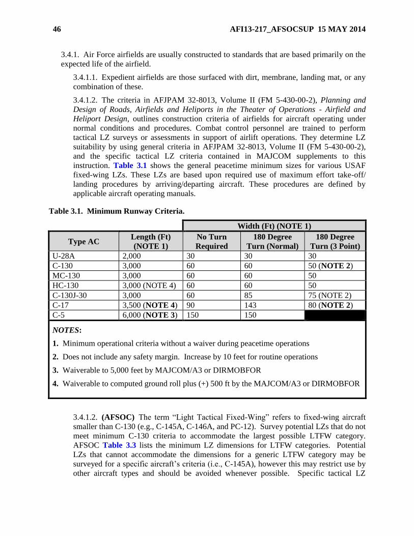
46 AFI13-217_AFSOCSUP 15 MAY 2014
3.4.1. Air Force airfields are usually constructed to standards that are based primarily on the
expected life of the airfield.
3.4.1.1. Expedient airfields are those surfaced with dirt, membrane, landing mat, or any
combination of these.
3.4.1.2. The criteria in AFJPAM 32-8013, Volume II (FM 5-430-00-2), Planning and
Design of Roads, Airfields and Heliports in the Theater of Operations - Airfield and
Heliport Design, outlines construction criteria of airfields for aircraft operating under
normal conditions and procedures. Combat control personnel are trained to perform
tactical LZ surveys or assessments in support of airlift operations. They determine LZ
suitability by using general criteria in AFJPAM 32-8013, Volume II (FM 5-430-00-2),
and the specific tactical LZ criteria contained in MAJCOM supplements to this
instruction. Table 3.1 shows the general peacetime minimum sizes for various USAF
fixed-wing LZs. These LZs are based upon required use of maximum effort take-off/
landing procedures by arriving/departing aircraft. These procedures are defined by
applicable aircraft operating manuals.
Table 3.1. Minimum Runway Criteria.
Width (Ft) (NOTE 1)
Type AC Length (Ft)
(NOTE 1)
No Turn
Required
180 Degree
Turn (Normal)
180 Degree
Turn (3 Point)
U-28A 2,000 30 30 30
C-130 3,000 60 60 50 (NOTE 2)
MC-130 3,000 60 60 50
HC-130 3,000 (NOTE 4) 60 60 50
C-130J-30 3,000 60 85 75 (NOTE 2)
C-17 3,500 (NOTE 4) 90 143 80 (NOTE 2)
C-5 6,000 (NOTE 3) 150 150
NOTES:
1. Minimum operational criteria without a waiver during peacetime operations
2. Does not include any safety margin. Increase by 10 feet for routine operations
3. Waiverable to 5,000 feet by MAJCOM/A3 or DIRMOBFOR
4. Waiverable to computed ground roll plus (+) 500 ft by the MAJCOM/A3 or DIRMOBFOR
3.4.1.2. (AFSOC) The term “Light Tactical Fixed-Wing” refers to fixed-wing aircraft
smaller than C-130 (e.g., C-145A, C-146A, and PC-12). Survey potential LZs that do not
meet minimum C-130 criteria to accommodate the largest possible LTFW category.
AFSOC Table 3.3 lists the minimum LZ dimensions for LTFW categories. Potential
LZs that cannot accommodate the dimensions for a generic LTFW category may be
surveyed for a specific aircraft’s criteria (i.e., C-145A), however this may restrict use by
other aircraft types and should be avoided whenever possible. Specific tactical LZ
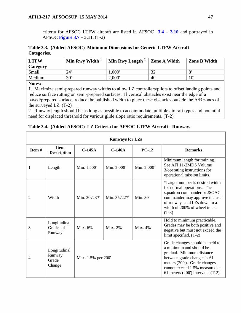
AFI13-217_AFSOCSUP 15 MAY 2014 47
criteria for AFSOC LTFW aircraft are listed in AFSOC 3.4 – 3.10 and portrayed in
AFSOC Figure 3.7 – 3.11. (T-2)
Table 3.3. (Added-AFSOC) Minimum Dimensions for Generic LTFW Aircraft
Categories.
LTFW
Category
Min Rwy Width 1 Min Rwy Length
2 Zone A Width Zone B Width
Small 24' 1,000' 32' 8'
Medium 30' 2,000' 40' 10'
Notes:
1. Maximize semi-prepared runway widths to allow LZ controllers/pilots to offset landing points and
reduce surface rutting on semi-prepared surfaces. If vertical obstacles exist near the edge of a
paved/prepared surface, reduce the published width to place these obstacles outside the A/B zones of
the surveyed LZ. (T-2)
2. Runway length should be as long as possible to accommodate multiple aircraft types and potential
need for displaced threshold for various glide slope ratio requirements. (T-2)
Table 3.4. (Added-AFSOC) LZ Criteria for AFSOC LTFW Aircraft - Runway.
Runways for LZs
Item # Item
Description C-145A C-146A PC-12 Remarks
1 Length Min. 1,500’ Min. 2,000’ Min. 2,000’
Minimum length for training.
See AFI 11-2MDS Volume
3/operating instructions for
operational mission limits.
2 Width Min. 30'/23'* Min. 35'/22'* Min. 30'
*Larger number is desired width
for normal operations. The
squadron commander or JSOAC
commander may approve the use
of runways and LZs down to a
width of 200% of wheel track.
(T-3)
3
Longitudinal
Grades of
Runway
Max. 6% Max. 2% Max. 4%
Hold to minimum practicable.
Grades may be both positive and
negative but must not exceed the
limit specified. (T-2)
4
Longitudinal
Runway
Grade
Change
Max. 1.5% per 200'
Grade changes should be held to
a minimum and should be
gradual. Minimum distance
between grade changes is 61
meters (200'). Grade changes
cannot exceed 1.5% measured at
61 meters (200') intervals. (T-2)
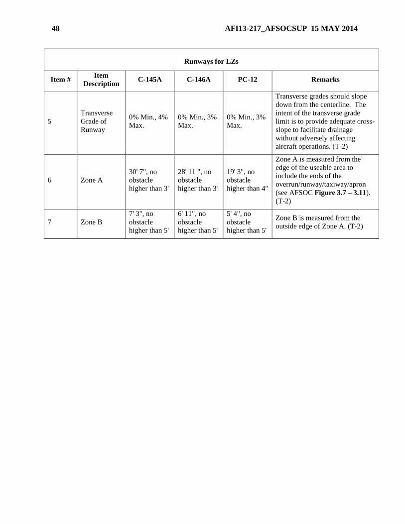
48 AFI13-217_AFSOCSUP 15 MAY 2014
Runways for LZs
Item # Item
Description C-145A C-146A PC-12 Remarks
5
Transverse
Grade of
Runway
0% Min., 4%
Max.
0% Min., 3%
Max.
0% Min., 3%
Max.
Transverse grades should slope
down from the centerline. The
intent of the transverse grade
limit is to provide adequate cross-
slope to facilitate drainage
without adversely affecting
aircraft operations. (T-2)
6 Zone A
30' 7", no
obstacle
higher than 3'
28' 11 ", no
obstacle
higher than 3'
19' 3", no
obstacle
higher than 4"
Zone A is measured from the
edge of the useable area to
include the ends of the
overrun/runway/taxiway/apron
(see AFSOC Figure 3.7 – 3.11).
(T-2)
7 Zone B
7' 3", no
obstacle
higher than 5'
6' 11", no
obstacle
higher than 5'
5' 4", no
obstacle
higher than 5'
Zone B is measured from the
outside edge of Zone A. (T-2)
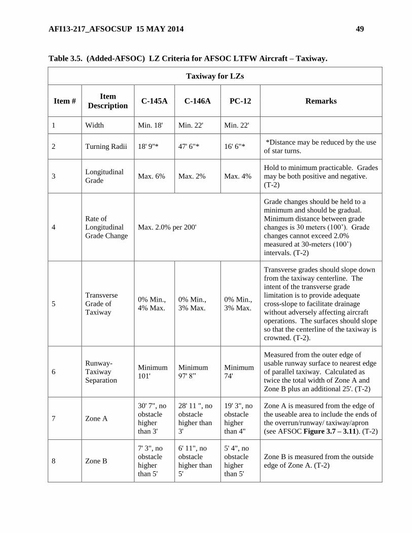
AFI13-217_AFSOCSUP 15 MAY 2014 49
Table 3.5. (Added-AFSOC) LZ Criteria for AFSOC LTFW Aircraft – Taxiway.
Taxiway for LZs
Item # Item
Description C-145A C-146A PC-12 Remarks
1 Width Min. 18' Min. 22' Min. 22'
2 Turning Radii 18' 9''* 47' 6"* 16' 6"* *Distance may be reduced by the use
of star turns.
3 Longitudinal
Grade Max. 6% Max. 2% Max. 4%
Hold to minimum practicable. Grades
may be both positive and negative.
(T-2)
4
Rate of
Longitudinal
Grade Change
Max. 2.0% per 200'
Grade changes should be held to a
minimum and should be gradual.
Minimum distance between grade
changes is 30 meters (100’). Grade
changes cannot exceed 2.0%
measured at 30-meters (100’)
intervals. (T-2)
5
Transverse
Grade of
Taxiway
0% Min.,
4% Max.
0% Min.,
3% Max.
0% Min.,
3% Max.
Transverse grades should slope down
from the taxiway centerline. The
intent of the transverse grade
limitation is to provide adequate
cross-slope to facilitate drainage
without adversely affecting aircraft
operations. The surfaces should slope
so that the centerline of the taxiway is
crowned. (T-2).
6
Runway-
Taxiway
Separation
Minimum
101'
Minimum
97' 8”
Minimum
74'
Measured from the outer edge of
usable runway surface to nearest edge
of parallel taxiway. Calculated as
twice the total width of Zone A and
Zone B plus an additional 25'. (T-2)
7 Zone A
30' 7", no
obstacle
higher
than 3'
28' 11 ", no
obstacle
higher than
3'
19' 3", no
obstacle
higher
than 4"
Zone A is measured from the edge of
the useable area to include the ends of
the overrun/runway/ taxiway/apron
(see AFSOC Figure 3.7 – 3.11). (T-2)
8 Zone B
7' 3", no
obstacle
higher
than 5'
6' 11", no
obstacle
higher than
5'
5' 4", no
obstacle
higher
than 5'
Zone B is measured from the outside
edge of Zone A. (T-2)
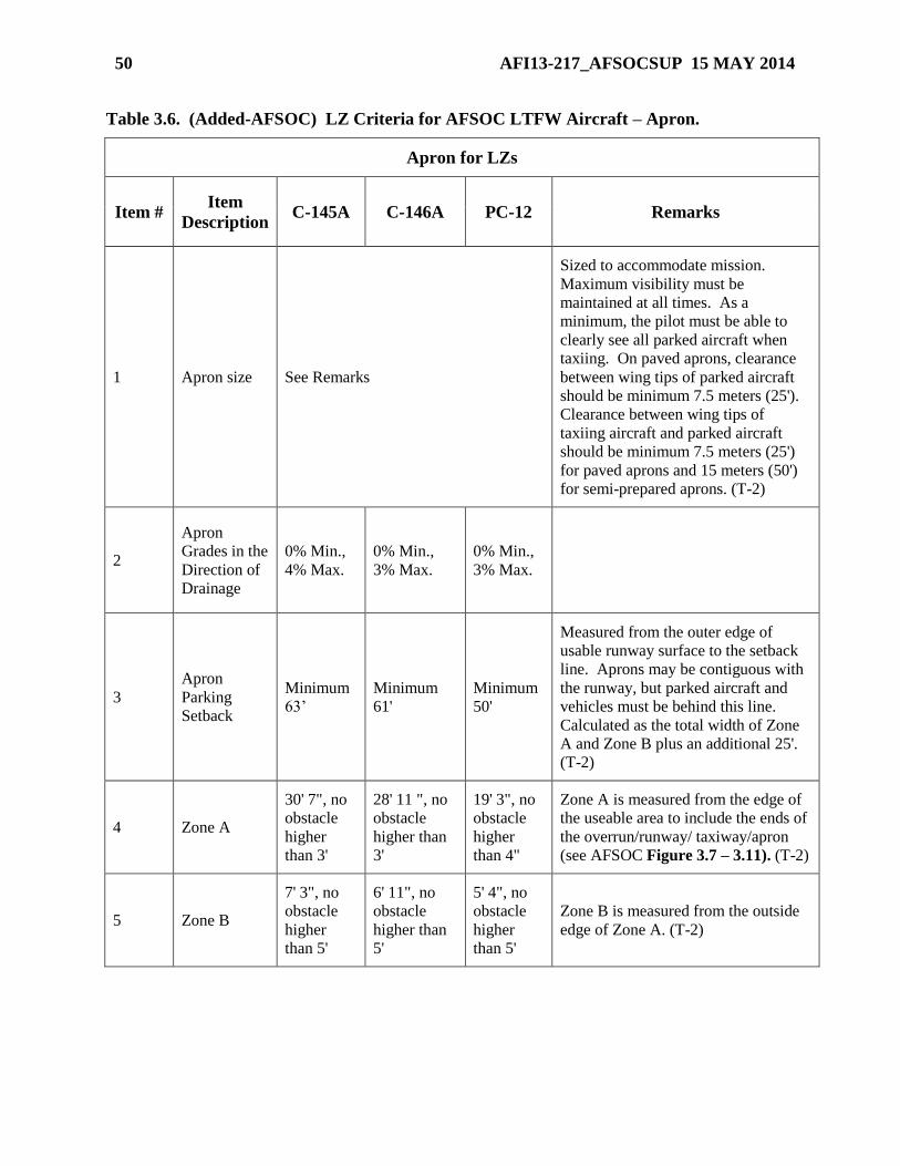
50 AFI13-217_AFSOCSUP 15 MAY 2014
Table 3.6. (Added-AFSOC) LZ Criteria for AFSOC LTFW Aircraft – Apron.
Apron for LZs
Item # Item
Description C-145A C-146A PC-12 Remarks
1 Apron size See Remarks
Sized to accommodate mission.
Maximum visibility must be
maintained at all times. As a
minimum, the pilot must be able to
clearly see all parked aircraft when
taxiing. On paved aprons, clearance
between wing tips of parked aircraft
should be minimum 7.5 meters (25').
Clearance between wing tips of
taxiing aircraft and parked aircraft
should be minimum 7.5 meters (25')
for paved aprons and 15 meters (50')
for semi-prepared aprons. (T-2)
2
Apron
Grades in the
Direction of
Drainage
0% Min.,
4% Max.
0% Min.,
3% Max.
0% Min.,
3% Max.
3
Apron
Parking
Setback
Minimum
63’
Minimum
61'
Minimum
50'
Measured from the outer edge of
usable runway surface to the setback
line. Aprons may be contiguous with
the runway, but parked aircraft and
vehicles must be behind this line.
Calculated as the total width of Zone
A and Zone B plus an additional 25'.
(T-2)
4 Zone A
30' 7", no
obstacle
higher
than 3'
28' 11 ", no
obstacle
higher than
3'
19' 3", no
obstacle
higher
than 4"
Zone A is measured from the edge of
the useable area to include the ends of
the overrun/runway/ taxiway/apron
(see AFSOC Figure 3.7 – 3.11). (T-2)
5 Zone B
7' 3", no
obstacle
higher
than 5'
6' 11", no
obstacle
higher than
5'
5' 4", no
obstacle
higher
than 5'
Zone B is measured from the outside
edge of Zone A. (T-2)
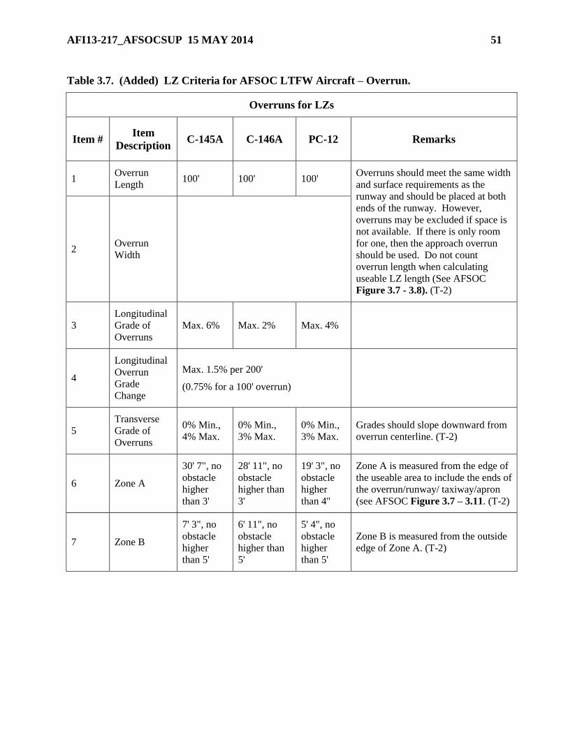
AFI13-217_AFSOCSUP 15 MAY 2014 51
Table 3.7. (Added) LZ Criteria for AFSOC LTFW Aircraft – Overrun.
Overruns for LZs
Item # Item
Description C-145A C-146A PC-12 Remarks
1 Overrun
Length 100' 100' 100'
Overruns should meet the same width
and surface requirements as the
runway and should be placed at both
ends of the runway. However,
overruns may be excluded if space is
not available. If there is only room
for one, then the approach overrun
should be used. Do not count
overrun length when calculating
useable LZ length (See AFSOC
Figure 3.7 - 3.8). (T-2)
2 Overrun
Width
3
Longitudinal
Grade of
Overruns
Max. 6% Max. 2% Max. 4%
4
Longitudinal
Overrun
Grade
Change
Max. 1.5% per 200'
(0.75% for a 100' overrun)
5
Transverse
Grade of
Overruns
0% Min.,
4% Max.
0% Min.,
3% Max.
0% Min.,
3% Max.
Grades should slope downward from
overrun centerline. (T-2)
6 Zone A
30' 7", no
obstacle
higher
than 3'
28' 11", no
obstacle
higher than
3'
19' 3", no
obstacle
higher
than 4"
Zone A is measured from the edge of
the useable area to include the ends of
the overrun/runway/ taxiway/apron
(see AFSOC Figure 3.7 – 3.11. (T-2)
7 Zone B
7' 3", no
obstacle
higher
than 5'
6' 11", no
obstacle
higher than
5'
5' 4", no
obstacle
higher
than 5'
Zone B is measured from the outside
edge of Zone A. (T-2)
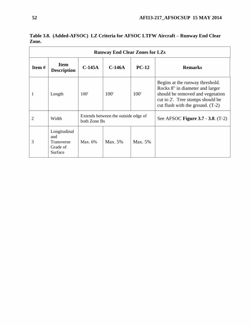
52 AFI13-217_AFSOCSUP 15 MAY 2014
Table 3.8. (Added-AFSOC) LZ Criteria for AFSOC LTFW Aircraft – Runway End Clear
Zone.
Runway End Clear Zones for LZs
Item # Item
Description C-145A C-146A PC-12 Remarks
1 Length 100' 100' 100'
Begins at the runway threshold.
Rocks 8" in diameter and larger
should be removed and vegetation
cut to 2'. Tree stumps should be
cut flush with the ground. (T-2)
2 Width Extends between the outside edge of
both Zone Bs See AFSOC Figure 3.7 - 3.8. (T-2)
3
Longitudinal
and
Transverse
Grade of
Surface
Max. 6% Max. 5% Max. 5%
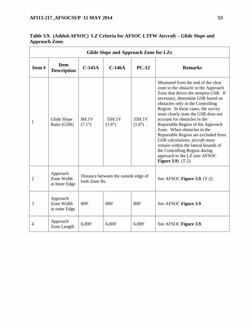
AFI13-217_AFSOCSUP 15 MAY 2014 53
Table 3.9. (Added-AFSOC) LZ Criteria for AFSOC LTFW Aircraft – Glide Slope and
Approach Zone.
Glide Slope and Approach Zone for LZs
Item # Item
Description C-145A C-146A PC-12 Remarks
1 Glide Slope
Ratio (GSR)
8H:1V
(7.1°)
35H:1V
(1.6°)
35H:1V
(1.6°)
Measured from the end of the clear
zone to the obstacle in the Approach
Zone that drives the steepest GSR. If
necessary, determine GSR based on
obstacles only in the Controlling
Region. In these cases, the survey
must clearly state the GSR does not
account for obstacles in the
Reportable Region of the Approach
Zone. When obstacles in the
Reportable Region are excluded from
GSR calculations, aircraft must
remain within the lateral bounds of
the Controlling Region during
approach to the LZ (see AFSOC
Figure 3.9). (T-2)
2
Approach
Zone Width
at Inner Edge
Distance between the outside edge of
both Zone Bs. See AFSOC Figure 3.9. (T-2)
3
Approach
Zone Width
at outer Edge
800' 800' 800' See AFSOC Figure 3.9.
4 Approach
Zone Length 6,000' 6,000' 6,000' See AFSOC Figure 3.9.
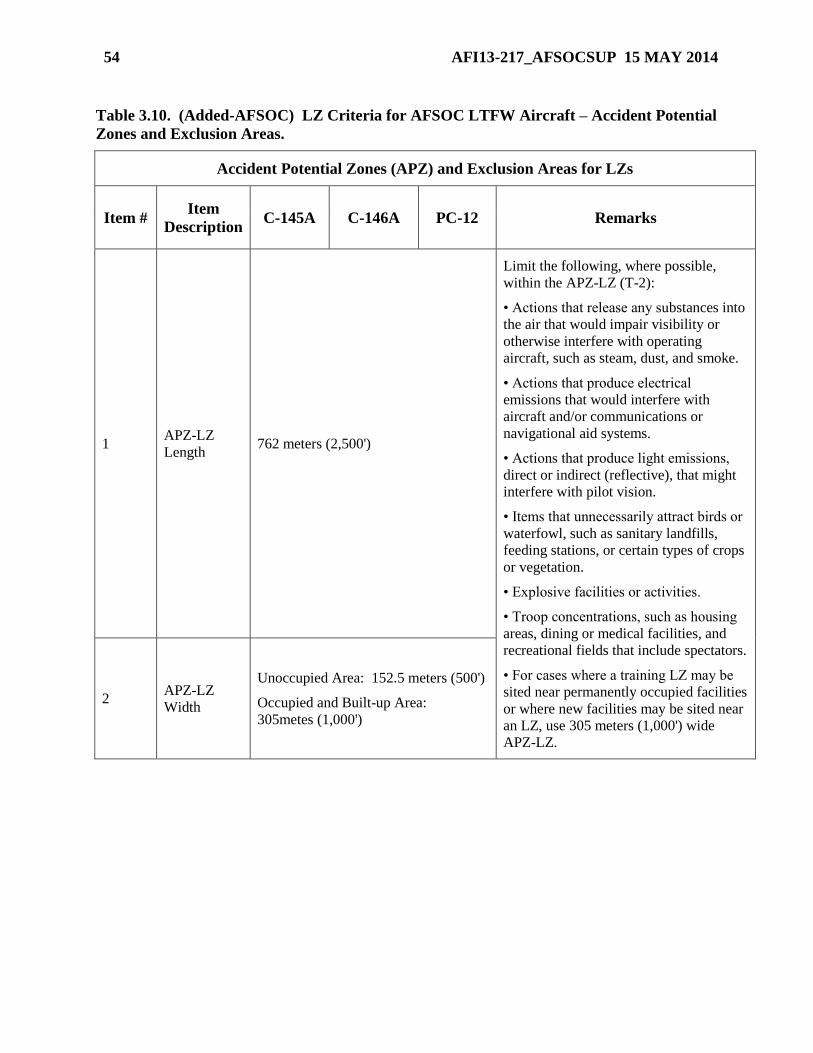
54 AFI13-217_AFSOCSUP 15 MAY 2014
Table 3.10. (Added-AFSOC) LZ Criteria for AFSOC LTFW Aircraft – Accident Potential
Zones and Exclusion Areas.
Accident Potential Zones (APZ) and Exclusion Areas for LZs
Item # Item
Description C-145A C-146A PC-12 Remarks
1 APZ-LZ
Length 762 meters (2,500')
Limit the following, where possible,
within the APZ-LZ (T-2):
• Actions that release any substances into
the air that would impair visibility or
otherwise interfere with operating
aircraft, such as steam, dust, and smoke.
• Actions that produce electrical
emissions that would interfere with
aircraft and/or communications or
navigational aid systems.
• Actions that produce light emissions,
direct or indirect (reflective), that might
interfere with pilot vision.
• Items that unnecessarily attract birds or
waterfowl, such as sanitary landfills,
feeding stations, or certain types of crops
or vegetation.
• Explosive facilities or activities.
• Troop concentrations, such as housing
areas, dining or medical facilities, and
recreational fields that include spectators.
• For cases where a training LZ may be
sited near permanently occupied facilities
or where new facilities may be sited near
an LZ, use 305 meters (1,000') wide
APZ-LZ.
2 APZ-LZ
Width
Unoccupied Area: 152.5 meters (500')
Occupied and Built-up Area:
305metes (1,000')
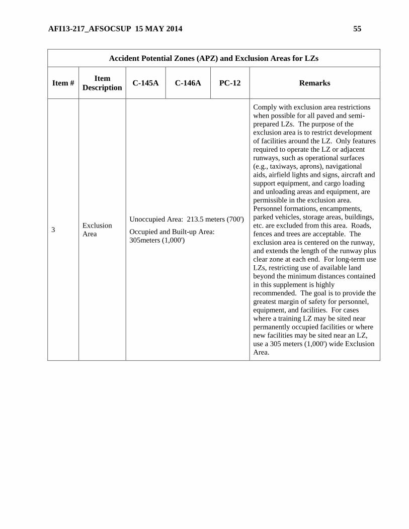
AFI13-217_AFSOCSUP 15 MAY 2014 55
Accident Potential Zones (APZ) and Exclusion Areas for LZs
Item # Item
Description C-145A C-146A PC-12 Remarks
3 Exclusion
Area
Unoccupied Area: 213.5 meters (700')
Occupied and Built-up Area:
305meters (1,000')
Comply with exclusion area restrictions
when possible for all paved and semi-
prepared LZs. The purpose of the
exclusion area is to restrict development
of facilities around the LZ. Only features
required to operate the LZ or adjacent
runways, such as operational surfaces
(e.g., taxiways, aprons), navigational
aids, airfield lights and signs, aircraft and
support equipment, and cargo loading
and unloading areas and equipment, are
permissible in the exclusion area.
Personnel formations, encampments,
parked vehicles, storage areas, buildings,
etc. are excluded from this area. Roads,
fences and trees are acceptable. The
exclusion area is centered on the runway,
and extends the length of the runway plus
clear zone at each end. For long-term use
LZs, restricting use of available land
beyond the minimum distances contained
in this supplement is highly
recommended. The goal is to provide the
greatest margin of safety for personnel,
equipment, and facilities. For cases
where a training LZ may be sited near
permanently occupied facilities or where
new facilities may be sited near an LZ,
use a 305 meters (1,000') wide Exclusion
Area.
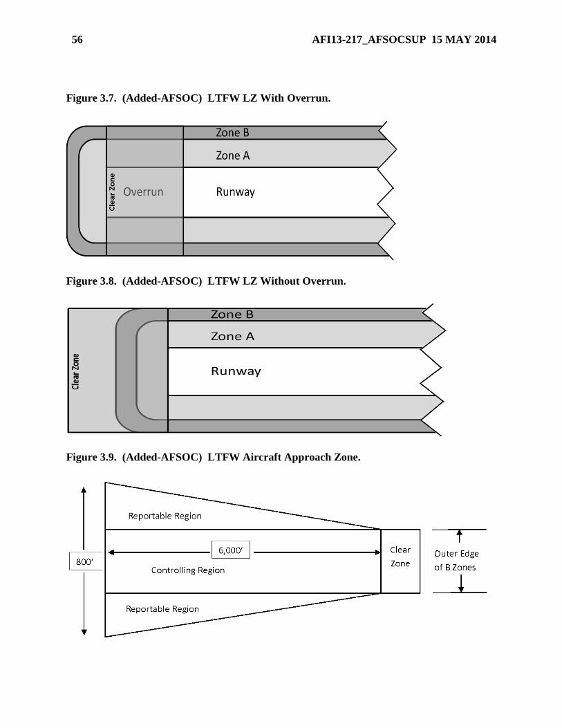
56 AFI13-217_AFSOCSUP 15 MAY 2014
Figure 3.7. (Added-AFSOC) LTFW LZ With Overrun.
Figure 3.8. (Added-AFSOC) LTFW LZ Without Overrun.
Figure 3.9. (Added-AFSOC) LTFW Aircraft Approach Zone.
AFI13-217_AFSOCSUP 15 MAY 2014 57
3.4.1.3. Airfield construction is generally done following the guidelines in AFJPAM 32-
8013, Volume II (FM 5-430-00-2). However, criteria to be utilized in a specific theater of
operations is based on local conditions and determined by Army and Air Force staff
engineers acting for the joint force commander.
3.4.2. Potential LZ areas fall into two basic categories: prepared, and semi-prepared
(unpaved). Prepared areas may include existing airfields, roads, highways, or other paved
surfaces. Semi-prepared surfaces are natural areas such as deserts, dry lakebeds, and flat
valley floors. These surfaces offer the ability to construct short airstrips for a limited use and
may or may not have an aggregate surface.
3.4.3. Contingency Response Group (CRG) airfield assessment teams include Air Force
Civil Engineering Support Activity (AFCESA) personnel that are qualified to conduct
surveys of prepared and semi-prepared LZs.
3.4.4. Combat control personnel are trained and equipped with a full suite of surveying
equipment that can satisfactorily assess obstructions, penetrations, and approach zone
clearances. They are also trained and have equipment used to check weight-bearing
capability of LZs for both semi-prepared and prepared surfaces.
NOTE: Although qualified combat control personnel can establish usability of hard-surface LZs
for temporary operations, it is recommended that Air Force Civil Engineering Support Activity
(AFCESA) or some other dedicated civil engineering agency with more robust equipment
(Electronic Cone Penetrometer, Heavy Weight Deflectometer, etc.) be utilized for sustained
operations. AFCESA contact information can be found in any Engineering Technical Letter.
3.4.5. Combat control personnel who are graduates of the AFCESA Contingency Airfield
Pavement Evaluation Course are qualified to perform structural evaluations of all types of
pavement surfaces (hard or un-surfaced) and determine allowable number of passes and
maximum weights of aircraft that can safely use these surfaces. When results of these
structural evaluations exhibit uncharacteristic results, these personnel are trained to forward
the data to the MAJCOM pavement engineer for final determination.
3.4.6. Although combat controllers and AMLOs are not qualified to perform engineering
surveys, they may be required to assist the supporting forces commander as a designated
representative in selecting LZ sites.
3.4.7. Semi-permanent runways are usually surveyed by engineering units and do not require
a survey by combat control personnel. However, semi-permanent and permanent
installations, such as captured enemy airfields, must be assessed for possible aircraft hazards
and correct dimensions prior to use. Combat control personnel may be tasked to perform this
type of assessment using criteria outlined in paragraph 3.4.1.2.
NOTE: Combat control personnel normally only conduct hard surface assessments for the theater
commander during contingencies.
3.4.8. The combat controller or CRG airfield assessment team gathers data from the on-site
survey, prepares an LZ survey package using the AF IMT 3822, Landing Zone Survey, and
recommends approval or disapproval to the appropriate agency for use.
58 AFI13-217_AFSOCSUP 15 MAY 2014
3.4.9. During the survey process, if there is any potential for impact or damage to the
environment due to the construction or modification of new or existing LZs, follow the
procedures within AFI 32-7061, The Environmental Impact Analysis Process.
3.5. General Landing Zone Criteria. Combat controllers may be required to assist in selecting
LZs. General guidelines are available in AFJPAM 32-8013, Volume 2 (FM 5-430-00-2) and
ETLs. Specific tactical LZ criteria for the type aircraft involved are contained in applicable
MAJCOM supplements to this instruction. Additionally, the following general data applies to LZ
criteria:
NOTE: ST units will use AFCESA ETL 04-7, C-130 and C-17 Contingency and Training
Airfield Dimensional Criteria, and ETL 02-19, Airfield Pavement Evaluation, Standards and
Procedures. Electronic copies are available at:
http://www.afcesa.af.mil/library/etl.asp?Category=Engineering%20Technical%20Letters.
3.5. (AFSOC)General Landing Zone Criteria. Specific tactical LZ criteria for AFSOC
LTFW aircraft are listed in AFSOC Table 3.4 – 3.10 and depicted in AFSOC Figure 3.7 – 3.11.
3.5.1. Size and Terrain. LZs should be of sufficient size to permit rapid takeoff, landing, and
loading operations. Terrain may be of soil, dirt, sand, or another suitable surface.
Consideration must be given to the slope and elevation of the runway, aircraft capability,
taxiways, and loading restrictions including their ability to support aircraft weight. Criteria
for the layout of newly constructed LZs are listed in detail in AFJPAM 32-8013, Volume II
(FM 5-430-00-2), Table 11-3. Table 3.1 shows the general minimum sizes for various fixed-
wing LZs. For criteria that are more specific, see MAJCOM publications.
3.5.1. (AFSOC) Minimum runway width for AFSOC LTFW is 200% of wheel track.
Specific LTFW MDS may require wider runways for routine/normal operations or based on
crew qualification; refer to AFSOC Table 3.4 – 3.10 for additional information.
3.5.1.1. (Added-AFSOC) See AFSOC Table 3.4 – 3.10 for the minimum LZ
dimensions for AFSOC LTFW aircraft.
3.5.1.2. (Added-AFSOC) AFSOC LTFW aircraft have published lateral obstruction
clearance criteria based A and B Zones. The size (width) of these zones is based on
aircraft wing span and wheel track and determined using the formulas provided in
AFSOC Figure 3.10. Zone A extends outward from the edge of the surveyed runway
width. Zone B extends outward from the outside edge of Zone A. Figure 3.11 depicts
the Zone A/B location.
3.5.1.2.1. (Added-AFSOC) It is acceptable to conduct operations on an LZ whose
survey lists a Zone B width that is less than the aircraft’s stated requirement, provided
the Zone A width listed on the survey exceeds the aircraft’s minimum requirement by
an equal or greater distance. For example, a C-145A may operate on an LZ with a 31'
Zone A and a 7' Zone B. In this case the Zone B is 3" less than required but the Zone
A is 5" greater than required.
3.5.1.2.2. (Added-AFSOC) Insufficient Zone A and/or Zone B survey distances
may be expanded by reducing runway width by an equal amount, down to the
minimum runway width requirement. For example, a C-146A aircrew desires to land
at an LZ with a runway that is 40' wide, with Zone As of 28' and Zone Bs of 7'. The
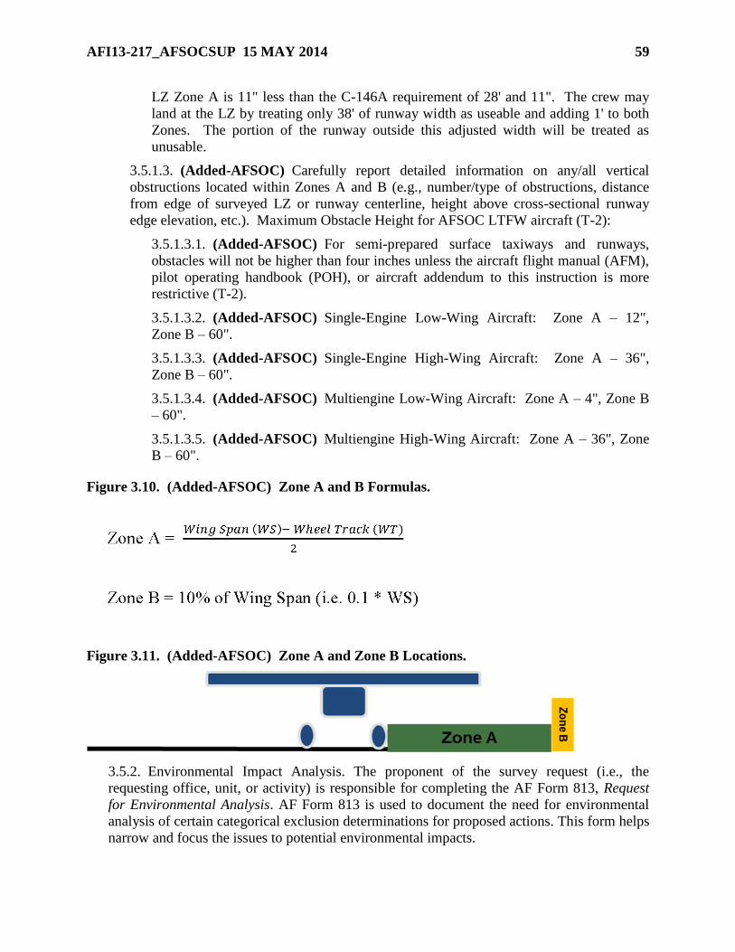
AFI13-217_AFSOCSUP 15 MAY 2014 59
LZ Zone A is 11" less than the C-146A requirement of 28' and 11". The crew may
land at the LZ by treating only 38' of runway width as useable and adding 1' to both
Zones. The portion of the runway outside this adjusted width will be treated as
unusable.
3.5.1.3. (Added-AFSOC) Carefully report detailed information on any/all vertical
obstructions located within Zones A and B (e.g., number/type of obstructions, distance
from edge of surveyed LZ or runway centerline, height above cross-sectional runway
edge elevation, etc.). Maximum Obstacle Height for AFSOC LTFW aircraft (T-2):
3.5.1.3.1. (Added-AFSOC) For semi-prepared surface taxiways and runways,
obstacles will not be higher than four inches unless the aircraft flight manual (AFM),
pilot operating handbook (POH), or aircraft addendum to this instruction is more
restrictive (T-2).
3.5.1.3.2. (Added-AFSOC) Single-Engine Low-Wing Aircraft: Zone A – 12",
Zone B – 60".
3.5.1.3.3. (Added-AFSOC) Single-Engine High-Wing Aircraft: Zone A – 36",
Zone B – 60".
3.5.1.3.4. (Added-AFSOC) Multiengine Low-Wing Aircraft: Zone A – 4", Zone B
– 60".
3.5.1.3.5. (Added-AFSOC) Multiengine High-Wing Aircraft: Zone A – 36", Zone
B – 60".
Figure 3.10. (Added-AFSOC) Zone A and B Formulas.
Figure 3.11. (Added-AFSOC) Zone A and Zone B Locations.
3.5.2. Environmental Impact Analysis. The proponent of the survey request (i.e., the
requesting office, unit, or activity) is responsible for completing the AF Form 813, Request
for Environmental Analysis. AF Form 813 is used to document the need for environmental
analysis of certain categorical exclusion determinations for proposed actions. This form helps
narrow and focus the issues to potential environmental impacts.
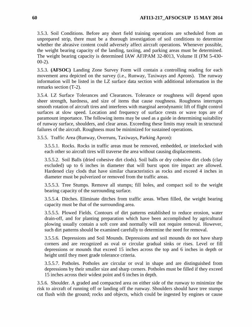
60 AFI13-217_AFSOCSUP 15 MAY 2014
3.5.3. Soil Conditions. Before any short field training operations are scheduled from an
unprepared strip, there must be a thorough investigation of soil conditions to determine
whether the abrasive content could adversely affect aircraft operations. Whenever possible,
the weight bearing capacity of the landing, taxiing, and parking areas must be determined.
The weight bearing capacity is determined IAW AFJPAM 32-8013, Volume II (FM 5-430-
00-2).
3.5.3. (AFSOC) Landing Zone Survey Form will contain a controlling reading for each
movement area depicted on the survey (i.e., Runway, Taxiways and Aprons). The runway
information will be listed in the LZ surface data section with additional information in the
remarks section (T-2).
3.5.4. LZ Surface Tolerances and Clearances. Tolerance or roughness will depend upon
sheer strength, hardness, and size of items that cause roughness. Roughness interrupts
smooth rotation of aircraft tires and interferes with marginal aerodynamic lift of flight control
surfaces at slow speed. Location and frequency of surface crests or wave tops are of
paramount importance. The following items may be used as a guide in determining suitability
of runway surface, shoulders, and clear areas. Exceeding these limits may result in structural
failures of the aircraft. Roughness must be minimized for sustained operations.
3.5.5. Traffic Area (Runway, Overruns, Taxiways, Parking Apron):
3.5.5.1. Rocks. Rocks in traffic areas must be removed, embedded, or interlocked with
each other so aircraft tires will traverse the area without causing displacements.
3.5.5.2. Soil Balls (dried cohesive dirt clods). Soil balls or dry cohesive dirt clods (clay
excluded) up to 6 inches in diameter that will burst upon tire impact are allowed.
Hardened clay clods that have similar characteristics as rocks and exceed 4 inches in
diameter must be pulverized or removed from the traffic areas.
3.5.5.3. Tree Stumps. Remove all stumps; fill holes, and compact soil to the weight
bearing capacity of the surrounding surface.
3.5.5.4. Ditches. Eliminate ditches from traffic areas. When filled, the weight bearing
capacity must be that of the surrounding area.
3.5.5.5. Plowed Fields. Contours of dirt patterns established to reduce erosion, water
drain-off, and for planting preparation which have been accomplished by agricultural
plowing usually contain a soft core and normally will not require removal. However,
such dirt patterns should be examined carefully to determine the need for removal.
3.5.5.6. Depressions and Soil Mounds. Depressions and soil mounds do not have sharp
corners and are recognized as oval or circular gradual sinks or rises. Level or fill
depressions or mounds that exceed 15 inches across the top and 6 inches in depth or
height until they meet grade tolerance criteria.
3.5.5.7. Potholes. Potholes are circular or oval in shape and are distinguished from
depressions by their smaller size and sharp corners. Potholes must be filled if they exceed
15 inches across their widest point and 6 inches in depth.
3.5.6. Shoulder. A graded and compacted area on either side of the runway to minimize the
risk to aircraft of running off or landing off the runway. Shoulders should have tree stumps
cut flush with the ground; rocks and objects, which could be ingested by engines or cause
AFI13-217_AFSOCSUP 15 MAY 2014 61
damage to the bottom of the aircraft should be removed. Shoulders are normally 10 feet wide
with a maximum positive or negative grade of 3%.
3.5.6. (AFSOC) Shoulders are not required for AFSOC LTFW aircraft. See AFSOC
Table 3.4 - 3.10 for LTFW aircraft LZ criteria.
3.5.7. Graded Area (previously clear area). An area located adjacent to and outside of the
runway shoulders. Grades may slope up or down to provide drainage, but may not penetrate
the primary surface. The minimum grade is 2% and the maximum is 5%. Graded areas
should not have any obstacles over 4 inches high except vegetation, runway edge markers,
runway distance remaining markers, Mobile Aircraft Arresting Systems (MAAS), and/or
other visual or electronic navigational aids which must be sited in this area due to their
function. Width of graded area varies from 35 feet (10.7m) to 375 feet (114.3m) depending
upon type aircraft the airfield is intended to support. Appropriate dimensions are contained in
MAJCOM supplements to this instruction.
3.5.7. (AFSOC) Graded areas are not required for AFSOC LTFW aircraft. See AFSOC
Table 3.4 - 3.10 for LTFW aircraft LZ criteria.
3.5.8. Clear Zone. A cleared area located at each end of the runway. Width is normally equal
to runway, shoulders, and clear areas and length is normally 500 feet or 1,000 feet (152.4m
or 304.8m).
3.5.8. (AFSOC) See AFSOC Table 3.8 for LTFW aircraft clear zone requirements.
3.5.9. Transitional Area (previously lateral safety zone). The normal width requirements are
30 feet U-28A, 60 feet (C-130), or 70 feet (C-17), extending outward from the graded area
with a maximum positive slope of 10% and a maximum negative slope of 20%. Transitional
areas should meet the criteria for the most restrictive type of aircraft using the LZ.
3.5.9. (AFSOC) Transitional Areas are not required for AFSOC LTFW aircraft. See
AFSOC Table 3.4 - 3.10 for LTFW aircraft LZ criteria.
3.5.10. Approach Zones. A trapezoidal area extending outward from each clear zone within
which no object may penetrate the glideslope angle. Approach zones should meet the criteria
for the type of aircraft using the LZ. The normal clearance surface is established on a 35:1
ratio for U-28A and C-130 operations and 20:1 for C-17 operations.
3.5.10. (AFSOC) The Approach Zone may be segmented into Controlling and Reportable
Regions, if required (see AFSOC Figure 3.9). If segmented into Controlling and Reportable
regions, report the most conservative glide slope ratio based obstructions in the Controlling
Region. The minimum width of the Controlling Region is the distance between the outer
edge of the surveyed B Zones. The actual glide slope ratio will be reported (e.g., if the
controlling obstacle is a 70’ tall tower 2,900’ from the end of the clear zone, the GSR will be
reported as 41:1). Report all vertical obstructions in the Approach Zone that penetrate a 35:1
GSR measured from the end of the clear zone. (T-2)
3.5.10.1. (Added-AFSOC) If an LZ has vertical obstructions in the controlling region
of the Approach Zone and is intended for use by LTFW aircraft with different glide slope
requirements (e.g., 8:1 for C-145A and 35:1 for C-146A), annotate the threshold
coordinates for the steepest glide slope (e.g., 8:1) as the approach end of runway in Block
9 of the AF Form 3822 , Landing Zone Survey. Include the coordinates for a displaced
62 AFI13-217_AFSOCSUP 15 MAY 2014
threshold location (e.g., 35:1) along with displacement distance (in feet) in the remarks
section of the survey form. Ensure sufficient vertical obstruction information is provided
(i.e., obstruction height, distance from end of clear zone, etc.) to allow crew members of
other aircraft types to calculate displaced threshold locations based on the requirements
of their platform. (T-2)
3.5.11. Overrun. A graded and compacted portion of the clear zone, located as an extension
to the end of the runway. An overrun is normally not considered part of the usable runway
when establishing airfield markings. Do not include overrun distances to calculate the
available LZ length required for operations. Overruns are used to minimize risk to aircraft
due to overrun on takeoff or undershooting a landing. The width is normally equal to that of
the runway and the type of aircraft involved determines length. See MAJCOM supplements
to this instruction.
3.5.11. (AFSOC) See AFSOC Table 3.7 for LTFW aircraft overrun requirements.
3.6. Landing Zone Markings.
3.6.1. LZ Marking Equipment. LZs are normally marked with VS-17 marker panels secured
to upright supports for day operations and omni-directional visible lighting systems with a
minimum output rating of 15 candela, and strobe lights if required, for night operations. The
C-17 uses the visual landing zone marker panel (VLZMP). Virtually any type overt lighting
or marking system is acceptable, if all participating units are briefed, and concur with its use.
ST units may also use specialized clandestine lighting systems.
3.6.2. LZ Markings and Identification. Specific details must be determined concerning the
type and location of LZ markings as well as airfield identification procedures. Consider
existing international agreements. LZ markings and identification procedures must be briefed
to all associated ground and aircrew members.
3.6.2. (AFSOC) Special consideration must be given before using AFSOC, 193 SOW, and
919 SOW “C130 only” or LTFW aircraft marking patterns to ensure operations will not
include non-AFSOC aircraft. (T-2)
3.6.3. Airfield Markings. Utilize conventional airfield markings consistent with flying
safety. When landings can be anticipated at both ends of the LZ, ensure touchdown areas are
marked at both ends.
3.6.4. Airfield Marking Patterns (AMP). In general, there are four standard types of airfield
marking patterns, designated AMP-1 through AMP-4. These correspond to the type airland
mission being supported and are used to simplify mission tasking. A 300 foot underrun and
overrun are required for all LZ operations. The four standard LZ marking types include:
3.6.4.1. AMP-1. Normally used to support day or night VMC tactical airlift missions.
See Figure 3.1 for day markings and Figure 3.2 for night/instrument markings. These
markings also implement STANAG 3601 and ASIC AIR STD 44/37C requirements.
When using the AMP-1 pattern, aircrew mission planners are authorized to reduce or
eliminate panel markings for well-defined runways during day VMC operations. As a
minimum, the touchdown zone must be marked.
AFI13-217_AFSOCSUP 15 MAY 2014 63
3.6.4.1.1. AMP-1 (Instrument Approach). Instrument approaches for contingency
landing zones require special configuration. This configuration is used to support day
or night tactical airlift missions during times of reduced visibility. Aircrew mission
planners are not authorized to reduce or eliminate panels, lights, or electronic
navigational aids during limited visibility operations.
3.6.4.1.1.1. Minimum requirements include the following: Special Tactics
personnel, ground-to-air radio communications, AN/TRN-45 Mobile Microwave
Landing System (MMLS) and the Contingency Airfield Night Lighting System
(CANLS). CANLS consists of two sequenced flashing lights, either side of the
approach end of the runway, and five sequenced flashing lights on extended
runway centerline at 300 feet intervals, Standard AMP 1 (Night/Instrument)
Landing Zone markings, and an IFR modified TRN-41 portable TACAN. See
Figure 3.2 for placement and configuration of these components.
NOTE: Minimum requirements allow single direction approaches. An additional MMLS and
approach lights are required if bi-directional approaches are desired or required.
3.6.4.1.1.2. Location of the MMLS is based on a Special Tactics Team LZ
Survey (runway length, obstacles, and airfield layout are all considerations) but is
ultimately based on final Terminal Instrument Procedures approach
plates/approval. However, for planning purposes, for a runway 5,000 feet or less
in length, position the co-located MMLS 300 feet from the threshold and 200 feet
right of centerline. For a runway greater than 5,000 feet in length, position the
MMLS 700 feet from the threshold and 200 feet right of centerline.
3.6.4.1.1.3. A FAA flight check or military aircraft flyability check will be
accomplished prior to using the landing zone/airfield for sustained operations.
3.6.4.2. AMP-2. AMP-2 can also be used to support day or night tactical airlift
requirements. AMP-2 requires fewer panels or lights than AMP-1. Overt or covert
lighting may be used. See Figure 3.3 and Figure 3.4.
3.6.4.3. AMP-3. AMP-3 further reduces the number of panels/lights used to support day
or night tactical airlift requirements. Overt or covert lighting may be used. The “Box and
One” is for runway identification only, and the box length will be 500 feet. See Figure
3.5 and Figure 3.6.
3.6.4.3. (AFSOC) The box length may be 500' or 1000' for AFSOC C-130 aircraft
depending on the tactical situation. The box length may be 200' for LTFW aircraft. If
the box length is not 500', it is mandatory the LZ controlling authority ensures all
participating aircraft are notified of the nonstandard box length. (T-2). See Figures
3.5 and Figure 3.6.
3.6.4.4. AMP-4. No markings are required.
3.6.5. Marking Considerations:
3.6.5.1. The LZ markings must be clearly visible to the pilot as early on the approach as
possible.
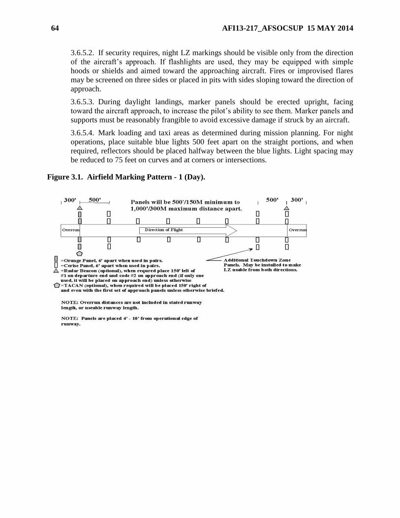
64 AFI13-217_AFSOCSUP 15 MAY 2014
3.6.5.2. If security requires, night LZ markings should be visible only from the direction
of the aircraft’s approach. If flashlights are used, they may be equipped with simple
hoods or shields and aimed toward the approaching aircraft. Fires or improvised flares
may be screened on three sides or placed in pits with sides sloping toward the direction of
approach.
3.6.5.3. During daylight landings, marker panels should be erected upright, facing
toward the aircraft approach, to increase the pilot’s ability to see them. Marker panels and
supports must be reasonably frangible to avoid excessive damage if struck by an aircraft.
3.6.5.4. Mark loading and taxi areas as determined during mission planning. For night
operations, place suitable blue lights 500 feet apart on the straight portions, and when
required, reflectors should be placed halfway between the blue lights. Light spacing may
be reduced to 75 feet on curves and at corners or intersections.
Figure 3.1. Airfield Marking Pattern - 1 (Day).
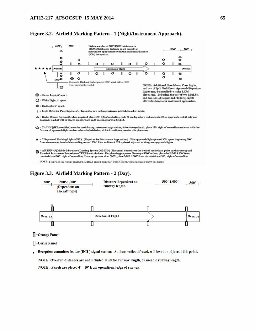
AFI13-217_AFSOCSUP 15 MAY 2014 65
Figure 3.2. Airfield Marking Pattern - 1 (Night/Instrument Approach).
Figure 3.3. Airfield Marking Pattern - 2 (Day).
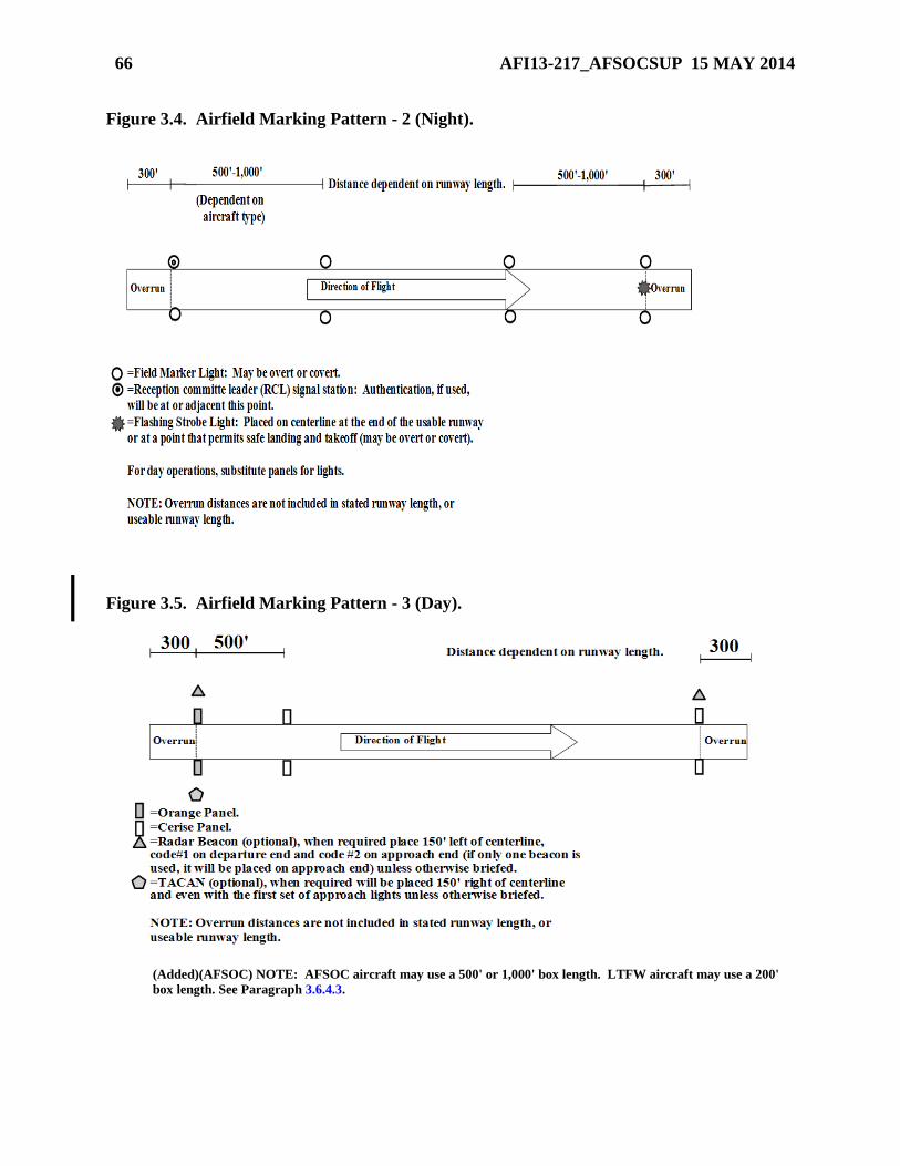
66 AFI13-217_AFSOCSUP 15 MAY 2014
Figure 3.4. Airfield Marking Pattern - 2 (Night).
Figure 3.5. Airfield Marking Pattern - 3 (Day).
(Added)(AFSOC) NOTE: AFSOC aircraft may use a 500' or 1,000' box length. LTFW aircraft may use a 200'
box length. See Paragraph 3.6.4.3.
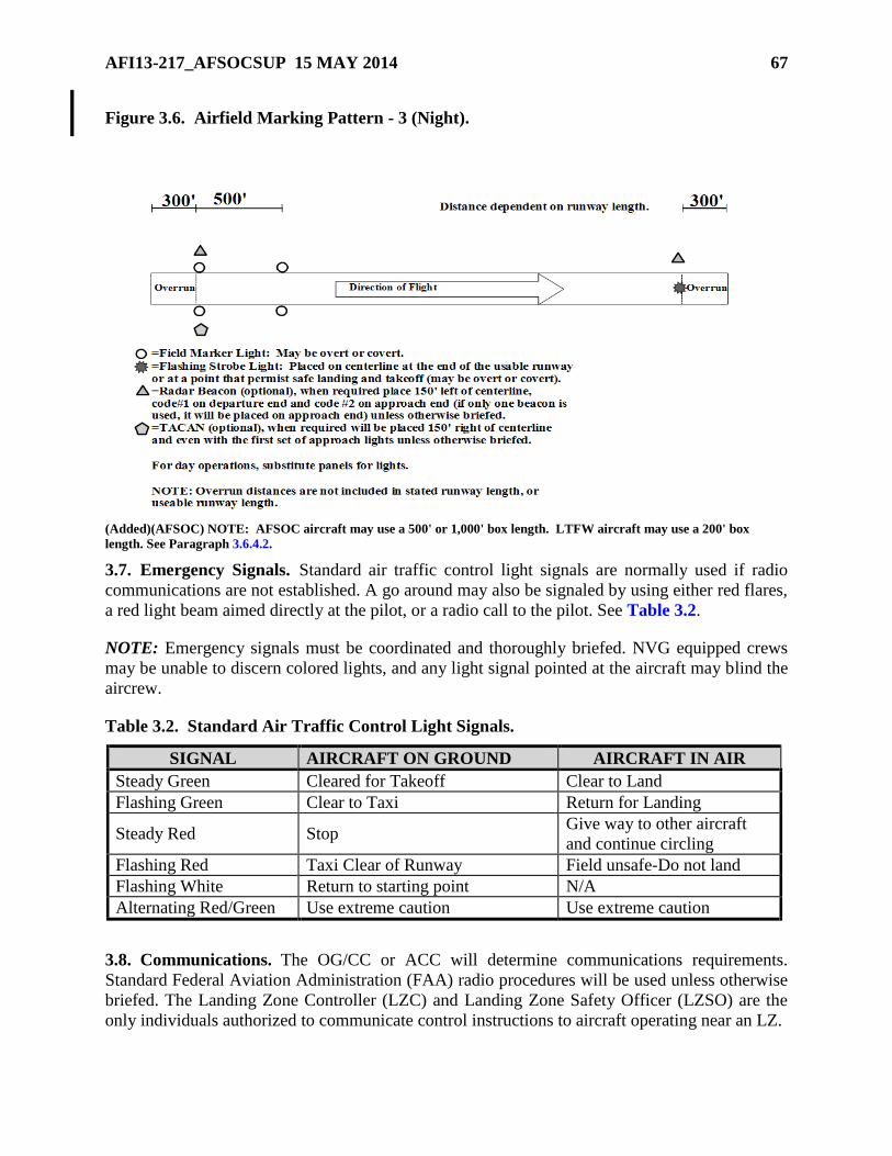
AFI13-217_AFSOCSUP 15 MAY 2014 67
Figure 3.6. Airfield Marking Pattern - 3 (Night).
(Added)(AFSOC) NOTE: AFSOC aircraft may use a 500' or 1,000' box length. LTFW aircraft may use a 200' box
length. See Paragraph 3.6.4.2.
3.7. Emergency Signals. Standard air traffic control light signals are normally used if radio
communications are not established. A go around may also be signaled by using either red flares,
a red light beam aimed directly at the pilot, or a radio call to the pilot. See Table 3.2.
NOTE: Emergency signals must be coordinated and thoroughly briefed. NVG equipped crews
may be unable to discern colored lights, and any light signal pointed at the aircraft may blind the
aircrew.
Table 3.2. Standard Air Traffic Control Light Signals.
SIGNAL AIRCRAFT ON GROUND AIRCRAFT IN AIR
Steady Green Cleared for Takeoff Clear to Land
Flashing Green Clear to Taxi Return for Landing
Steady Red Stop Give way to other aircraft
and continue circling
Flashing Red Taxi Clear of Runway Field unsafe-Do not land
Flashing White Return to starting point N/A
Alternating Red/Green Use extreme caution Use extreme caution
3.8. Communications. The OG/CC or ACC will determine communications requirements.
Standard Federal Aviation Administration (FAA) radio procedures will be used unless otherwise
briefed. The Landing Zone Controller (LZC) and Landing Zone Safety Officer (LZSO) are the
only individuals authorized to communicate control instructions to aircraft operating near an LZ.
68 AFI13-217_AFSOCSUP 15 MAY 2014
3.9. Terminal NAVAIDS. ST units have the capability to tactically employ and operate a
variety of NAVAIDS in support of LZ operations. The units deploy NAVAIDS, such as the
TACAN, ZM, mobile microwave landing system (MMLS), or radar beacons as directed by the
ACC. Standard NAVAID placement procedures are listed below; however, the tactical
environment will frequently require modifications of these standard placements.
3.9.1. TACAN. When used for instrument procedures, recommended placement is 150 feet
right of runway centerline abeam the first set of approach lights in an area free of excessive
aircraft, vehicle, and troop movements.
3.9.2. Radar Beacons. Since radar beacons transmit signals via “line-of-sight,” terrain on the
LZ and along the inbound course must be taken into consideration to allow the earliest
possible acquisition. Ensure aircrews are briefed on beacon placement. For AMP-1 through
AMP-3 Landings, place one radar beacon (code 2) 150 feet left of runway centerline abeam
the first set of steady lights (panels) in the touch down zone. Place a second beacon (code 1)
150 feet left of the departure end flashing strobe.
3.10. Landing Zone Personnel.
3.10.1. Minimum Personnel. A Landing Zone Safety Officer (LZSO) is required and,
depending on the operations, a Landing Zone Controller (LZC) may also be required.
3.10.1. (AFSOC) Special Operations Group (SOG)/CCs (or COMAFSOF) may waive the
requirement for an LZSO, as the minimum LZ personnel required. For training operations,
aircrews will conduct a minimum of one clearing pass prior to the initial touch down at an
unattended LZ. (T-2)
3.10.2. The LZC's primary function is to provide air traffic control services.
3.10.2. (AFSOC) Unit commanders may certify qualified government civilians or contract
civilians who were previous combat controllers as a LZC/LZSO.
3.10.2.1. The LZC will be a qualified combat controller certified by the unit commander
as capable of performing unilateral or joint air traffic control duties. ST units are
authorized to combine LZC/LZSO functions during VFR operations. When combined,
LZSO skill level requirements must be met.
3.10.3. The LZSO will normally be a qualified E-5 or above (seven or nine skill level)
combat control NCO, special tactics officer, AMLO, or airlift aircrew officer (U-28A, C-130
or C-17 aircrew officer for LZ operations) certified by the unit commander as capable of
performing as a LZSO.
3.10.3. (AFSOC) Unit commanders may certify government civilians or contract civilians
with the listed experience and proper training as a LZCO. All AFSOC rated officers with the
proper training may be LZCO certified by the unit commander.
3.10.3.1. During visual flight rules (VFR) operations not requiring Air Traffic Control
(ATC) services (Class G airspace), qualified Air Force Reserve Command (AFRC), Air
National Guard (ANG), and AF active duty personnel designated by their commander
may establish LZ markings. If the LZ is semi-prepared, they are restricted to operations
on their local training LZ. These personnel assume the LZSO responsibilities listed in
paragraph 3.10.4.
AFI13-217_AFSOCSUP 15 MAY 2014 69
NOTE: USAFWS Weapons Officer airlift cadre may perform LZSO duties at all approved CONUS LZs
not requiring an LZCO. These personnel assume LZSO duties and responsibilities listed in
3.10.4 provided they have received the HQ AFSOC formal training by a 7-level combat
controller or aircrew certified personnel formally trained by a 7-level combat controller.
Under no circumstances are personnel who fall under this category permitted to provide aircraft
with air traffic control services.
3.10.3.1.1. Aircrew member certification will consist of training coordinated between
the flying squadrons and ST. This training will be conducted using HQ AFSOC
formal lesson plans. The flying squadron commander will review/authorize unilateral
single-ship missions to landing zones without a LZC or an operating control tower
(Class G airspace).
3.10.3.1.2. Non-USAF / Non-aircrew personnel. If contingency operations require
USAF use of landing zones not defined within the scope of this AFI, or under the
operational control of non-USAF / non-aircrew personnel, a combat controller or
AMLO may train allied forces personnel (with ACC or DIRMOBFOR approval) to
perform LZSO duties IAW paragraph 3.10.4 of this instruction using approved HQ
AFSOC formal lesson plans. The instructor will provide a letter certifying personnel
to perform LZSO duties limited to the landing strip trained on and for a specified
duration.
3.10.3.2. Units listed in paragraph 2.17.3.2 are authorized to use qualified personnel to
establish LZs supporting single-ship VMC operations that do not require air traffic
control services (Class G airspace).
NOTE: Under no circumstances are personnel who fall under this category permitted to provide aircraft
with air traffic control services.
3.10.3.2.1. Civilian contract personnel who were previously qualified as a combat
controller, or were a C-130 or C-17 aircrew officer, must complete the HQ AFSOC
formal lesson plan and receive instruction IAW paragraph 3.10.3.1.1 before they are
authorized to control landing zone operations. These personnel assume the LZSO
responsibilities listed in paragraph 3.10.4. Previously qualified combat control
personnel may perform LZC functions provided their statement of work requires
those duties, they pass a flying class II physical and meet LZC currency requirements
outlined in AFSOCI 36-2204.
3.10.4. The LZSO represents the OG/CC or ACC as provided in mission directives and is
responsible for the following:
3.10.4.1. Ensuring required aircraft rescue and firefighting (ARFF) coverage is at the LZ
prior to beginning airland operations, and ensures continuous contact with ARFF is
maintained.
3.10.4.2. Maintaining close liaison with the using unit commander, or designated
representative, during joint operations.
70 AFI13-217_AFSOCSUP 15 MAY 2014
3.10.4.3. Observing and evaluating all factors that may adversely affect the safety and
efficiency of the operation.
3.10.4.4. Inspecting the LZ prior to use IAW paragraph 3.5, and validating the LZ meets
criteria listed on the current LZ survey.
3.10.4.5. Monitoring the conditions of the landing, taxi, and parking areas, and ensuring
the runway is free of obstacles before advising aircraft they are cleared to land/takeoff at
their own discretion.
3.10.4.6. Ensuring LZ markings and NAVAID placement are correct and operating.
3.10.4.7. Ground handling and marshaling of aircraft.
3.10.4.8. Evaluating and reporting surface wind and meteorological phenomenon.
3.10.4.9. Ensuring the dissemination of available altimeter settings.
3.10.4.10. Formulating minimum safe altitudes and monitoring the deconfliction of
artillery and close air support operations.
3.10.4.11. Advising the LZC if conditions are unsafe for landing operations and ensures
cancellation of operations is relayed to appropriate agencies.
3.10.4.12. Supervising all Air Force personnel on the LZ.
3.10.4.13. Maintaining contact with the LZC during the operation.
3.11. Rolling Friction Factor. When conducting operations on semi-prepared surfaces with C-
17 aircraft, the LZC/LZSO will determine the runway friction factor IAW ETL-97-9. C-17
mission planners optimally require this factor a minimum of 24hrs prior to airland operations.
3.11.1. This value will be reported to each departing C-17 prior to taxi, and again prior to
departure. This value will also be reported to arriving C-17 aircraft.
3.11.2. After each C-17 departure, or whenever the LZ team notices a discernable
deterioration of the LZ surface, they will re-determine the rolling friction factor. During
sustained operations, consideration to the ability to gather data must be realized. If the new
factor is not feasible, then C-17 aircraft will be given the last value noting the time it was
taken and how many sorties have taken place since that reading.
3.12. LZ Control Point Location. The LZC locates the control point after considering
pertinent factors such as security, runway in use, and view of the airfield and surrounding
airspace. Separation of aircraft and the ability to detect hazards on or near the operating area
supersede other concerns.
3.13. Aircraft Rescue and Fire Fighting Requirements. Specific requirements for ARFF are
contained in MAJCOM (i.e., AMCI 11-208, Tanker/Airlift Operations) publications. When
required, the user will preposition suitable equipment at the LZ prior to conducting operations.
3.14. Landing Zone Review Process. The following paragraphs outline the LZ survey process
from performing the initial groundwork to the final incorporation of the LZ into the ZAR
database. Use of the ZAR will expedite mission planning, enhance safety, and avoid duplication
of surveys. Information in the ZAR does not replace the need for a completed survey prior to
conducting landing zone operations. All completed surveys should be forwarded by the
AFI13-217_AFSOCSUP 15 MAY 2014 71
appropriate agencies to HQ AMC/A3DT for inclusion in the worldwide database. LZ surveys
become obsolete 5 years after date of MAJCOM approval (block 4C of AF Form 3822) and must
be resurveyed prior to use. Procedures for requesting an initial or re-survey of an LZ are
contained in paragraph 1.4.
NOTE: Other MAJCOMs and contingency AOCs may maintain their own ZAR database (if desired).
However, this does not alleviate them of the responsibility to provide these surveys to HQ
AMC/A3DT for inclusion in the worldwide ZAR database, unless classification requirements
dictate otherwise.
3.14.1. Combat control personnel or qualified civilians complete the AF IMT 3822,
Landing Zone Survey (Attachment 5). Qualified civilians may be a GS employee,
contractor, and/or temporary contractor hired by DoD to perform survey specific duties. All
qualified civilians will be trained IAW the current AFSOC survey training guidance and
meet AFSC 1C2X1, combat control, CFETP training requirements. Training will be
validated in a memorandum signed by the 720 STG/CC and tracked at the 720 OSS.
3.14.2. Following completion of the ground survey by combat control personnel or qualified
civilians, the AF IMT 3822 is forwarded to the appropriate chief, wing/group tactics, or as
designated by the OG/CC, for a safety-of-flight review. The MAJCOM/A3 or ACC or their
designated representative is final approval authority.
3.14.2. (AFSOC) Reviewing authority in order of preference is the group tactics officer;
group stan/eval officer, squadron operations officer or their representative. Final approval
authority is delegated to the OG/CC or COMAFSOF. (T-2)
3.14.2.1. Safety-of-Flight Review. A safety-of-flight review is completed by the nearest
Air Force wing/group tactics office on all LZ surveys. The purpose of a safety-of-flight
review is to ensure an aircraft can safely ingress, egress and operate in the vicinity of the
LZ. A safety-of-flight review includes an in-depth chart study of the terrain features,
obstructions to flight, and airspace restrictions along the route of flight to and from an
LZ. For a complete list of regional group/wing tactics offices see:
https://afkm.wpafb.af.mil/ASPs/CoP/OpenCoP.asp?Filter=OO-OP-AM-40. A
1:50,000-scale chart and satellite imagery (if available) should be used when available for
the objective area and at least a 1:250,000-scale chart for the ingress, egress and traffic
pattern. If approved by the MAJCOM, Portable Flight Planning Software (PFPS) may be
used instead of paper charts. The safety-of flight review lists all obstructions such as
terrain, towers, or power lines that may affect the aircraft’s ability to achieve ingress,
egress, traffic pattern altitudes and airspeeds. The safety-of-flight review will also review
any prohibited areas, restricted operating zones (ROZs), noise sensitive areas, special use
airspace, route of flight to avoid such areas, preferred routing, NOTAM requirements,
population areas etc. Evaluate terrain/obstructions within a radius of 5nm (minimum) and
10nm (desired) from the LZ centerpoint. High altitude penetrations to the LZ may require
evaluation of terrain/obstructions out to a 20nm radius. Evaluate likely avenues of
ingress/egress along runway centerline and others as mission planning requirements
dictate arrival/departure paths. Evaluation of terrain/obstructions should include service
ceiling and climb performance for the particular aircraft involved, the ability of the
aircraft to take-off/fly over the LZ at low speeds and escape from the LZ using 3-engine
72 AFI13-217_AFSOCSUP 15 MAY 2014
climb out rates. If these criteria cannot be met, the ingress/egress routing must be
modified, altitude raised, take-off/landing directions restricted to one-way operations, or
the safety-of-flight review denied.
3.14.3. The AF IMT 3822 is not valid for use until it has been reviewed and recommended
for use by the appropriate MAJCOM/A3 or the ACC. The AF IMT 3822 is then forwarded
for inclusion in the landing zone database.
3.14.3. (AFSOC) HQ AFSOC/A3 designates OG/CC (Wing/CC for National Guard Bureau
(NGB)) or COMAFSOF as final approval authority for landing zone surveys. If OG/CC or
COMAFSOF is not an O-6, approval authority rests with the first O-6 in the operational
chain of command.
3.14.4. The AF IMT 3822 documents the conditions that existed at the time the survey was
accomplished and may not account for changes to the LZ seasonal topography. The condition
of the LZ should be confirmed prior to commencing operations.
Section 3B—Helicopter Landing Zone Operations
3.15. General. Helicopters require their own landing zone procedures to safely operate in areas
unsuitable for fixed-wing aircraft. HLZ surveys are required for all training and exercises and
highly recommended as part of the normal mission planning for contingencies. HLZ surveys are
not required if another survey is available (ie. fixed wing LZ survey or FARP survey). The
paragraphs below define the procedures.
3.15. (AFSOC)General. AFSOC Tiltrotor units do not require a HLZ surveys for
MAJCOM/Joint Chief of Staff (JCS)-directed exercises or contingency operations. The
requirement to complete an AF Form 4303, Helicopter Landing Zone Survey, for training
remains in effect. (T-2)
3.16. Helicopter Landing Zone Selection. Helicopter landing zones (HLZ) are dependent on
the aircraft type and size, and whether the HLZ will be used for takeoffs/landings or alternate
insertion/extraction (AIE). Selecting the HLZ location is the joint responsibility of the ACC and
the supported force commander. JFSOCC forces determine their suitable locations from
JSOACC recommendations.
3.16.1. Weight Bearing Capacity. HLZs are dependent on the aircraft type or size. Weight
bearing capacity is not required for helicopter operations, but care must be exercised to
ensure the HLZ is cleared to prevent possible engine damage or personnel injury from flying
debris due to hover operations.
3.17. Helicopter Landing Zone Markings. MAJCOMs may supplement this instruction with
their unique requirements. There are no USAF requirements to mark HLZs for day or NVG use.
HLZs flown to unaided at night must be clearly marked with a minimum of two overt lights that
either outline or target obstruction free areas compatible with the aircraft being used.
Additionally, overt spot or landing lights must be available and used by the aircraft during the
approach.
3.18. Helicopter Landing Zone Survey Requirements. The HLZ survey program is a group
tactics function or an office with an equivalent level of expertise. Group tactics must ensure
surveys are conducted IAW the procedures below.
AFI13-217_AFSOCSUP 15 MAY 2014 73
3.18. (AFSOC)Helicopter Landing Zone Survey Requirements. The OG/CC may delegate
responsibility for the HLZ program to the squadron level (SOG Tactics will remain as the
repository of HLZ surveys, when accomplished, IAW Paragraph 3.19.4). (T-2)
3.18.1. Completing the HLZ survey process involves a physical inspection of the HLZ,
documenting the information on the AF Form 4303, Helicopter Landing Zone Survey, a
safety-of-flight review, and final approval. MAJCOMs will determine their own requirement
for HLZ surveys for AIE training. Surveys may be accomplished by the using units whose
equipment or personnel are being landed or for an AIE. For exercises and joint training
operations, users must ensure the survey is completed and meets the appropriate criteria for
operational and safety standards. The user must conduct a physical inspection of the HLZ
prior to use to identify and evaluate potential hazards to personnel/equipment, man-made or
natural structures, and ground personnel. If the survey was conducted using any other method
than GPS-derived coordinates, provide the reviewer with the raw coordinate data and the
method of conversion.
3.18.1. (AFSOC) The physical inspection/survey may be conducted via a high/low
reconnaissance (high/low recon) by any current and qualified instructor pilot. A physical
inspection/survey may also be accomplished during daytime by a current and qualified
aircraft commander. LZ’s designated for AIE training should follow the same criteria as for
regular HLZ’s, but should be annotated as “AIE Only” in the HLZ’s name and remarks
section. (T-2)
3.18.1.1. Host Nation (HN) HLZ Surveys. When conducting operations on or over a HN
surveyed HLZ, a review of the HN survey will be accomplished before operations to the
HLZ begin. Users remain responsible for ground operational and safety criteria.
3.18.1.2. A 1:50,000 scale chart or less should be used when available for the objective
area for the ingress and egress (Portable Flight Planning Software (PFPS) may be used
instead of paper charts if approved by the MAJCOM). The review lists all obstructions
such as terrain, towers, or power lines that may affect the helicopter’s route of flight.
Also listed on the review are any prohibited areas, noise sensitive areas, special use
airspace, route of flight to avoid such areas, preferred routing, NOTAM requirements,
etc. Evaluation of terrain/obstructions should consider the particular helicopter involved,
and the ability to fly over and/or land on the HLZ unless OGE hover power plus 5-
percent is available. If these criteria cannot be met, the ingress must be modified, or the
review denied.
3.18.1.2. (AFSOC) AFSOC crews may use PFPS for conducting HLZ survey reviews.
3.18.2. When conducting operations on a HLZ that was previously surveyed by another unit,
the commander of the using unit is responsible for ensuring the HLZ meets the criteria for
that operation. In all cases, the using unit must accept responsibility for all personnel injuries,
parachute or load damage, and property damage.
3.18.3. Tactical HLZ Surveys. During exercises and contingencies, when time or situations
do not permit completion of a full HLZ survey, a tactical HLZ survey may be required to
meet the appropriate commander’s objective(s).
74 AFI13-217_AFSOCSUP 15 MAY 2014
3.18.3.1. Though preferable, the use of an AF Form 4303 is not required for a tactical
survey. Requests and surveys may be passed electronically. As much information as
practical should be obtained and forwarded for review.
3.18.3.2. Requests for tactical surveys will be forwarded to the designated
exercise/contingency ACC for final review.
3.18.3.3. When using a tactical HLZ, the rotary-wing unit assumes responsibility for
helicopter safety-of-flight.
3.19. Helicopter Landing Zone Review Process. The following paragraphs outline the HLZ
review process from performing the initial groundwork to the final coordination. All completed
surveys will be forwarded to the group tactics office, or an office with an equivalent level of
expertise. Surveys will be reaccomplished when the user and/or provider determine changes in
the ground or air aspects of the HLZ data require a new survey.
3.19.1. The HLZ surveys will be conducted during daylight by a qualified combat controller;
survey qualified rotary wing aircrew member, Chief Group Weapons and Tactics, or a
qualified civilian. Qualified civilians will meet the training and documentation requirements
listed in para 3.14.1. AFSPC will establish requirements in their supplement for surveying
Missile Alert Facilities (MAF) and Launch Facilities. The surveyor (AF Form 4303, item
4A) performs the actual ground portion of the HLZ survey (i.e., measurements, coordinates,
calculating size, obtaining maps and creating diagrams) and annotates results on the AF Form
4303. The surveyor may be a member of the unit that intends to use the HLZ, or a member of
another unit may perform the ground portion of a survey if requested and time permits. To
facilitate future use of surveyed HLZs, initial surveys will encompass the largest area
available and will not be limited by specific mission requirements. The surveyor will forward
the completed survey to the group tactics office, or the OG/CC designated office, for review.
Include recommended use, any deviations from HLZ standards contained in service or
MAJCOM directives, and other pertinent remarks.
3.19.1. (AFSOC) The physical inspection/survey may be conducted via high/low recon by
any current and qualified instructor pilot. A physical inspection/survey may also be
accomplished during daytime by a current and qualified aircraft commander.
3.19.2. The reviewer, in order of preference, is the Chief, Group Tactics, Squadron
Commander, or Squadron Operations Officer (AFSPC/A3 may designate the helicpter
squadron commander and operations officer as reviewing officials). The reviewer (AF Form
4303, item 4B) ensures the HLZ can be safely used from a flight perspective. Throughout the
review process, HLZ survey packages will include all applicable maps, photos, charts and
diagrams necessary to determine the safety and utility of the HLZ.
3.19.2. (AFSOC) For AFSOC units the reviewer is waived to no lower than the assistant
operations officer. (T-2)
3.19.3. Approval Authority (AF Form 4303, item 4C). Prior to use, surveys will be approved
for air operations by the OG/CC or appropriate ACC. This approval assures the review has
been accomplished and the HLZ is considered safe for air operations.
AFI13-217_AFSOCSUP 15 MAY 2014 75
3.19.3. (AFSOC) If a JSOAC or JSOTF is established, the JSOAC/CC or JSOTF/CC may
sign item 4C. The approval authority is waived to the squadron commander, or the first O-5
in the chain of command. (T-2)
3.19.4. Once item 4C of AF Form 4303 is completed, the survey is ready for use. Respective
group tactics offices are the local area repositories for HLZ surveys. AFSPC/A3 will
designate an office to serve as a repository for LZ surveys.
3.19.5. HLZ surveys document the conditions that existed at the time the survey was
accomplished, and may not account for changes to seasonal topography. Recommended uses
may be based on minimum requirements and should not be misconstrued to be all-inclusive
(i.e., a HLZ recommended for two MH-53s may not be suitable for a CV-22). It is the
responsibility of the flying and ground units involved to ensure that any HLZ being
considered for use meets the requirements for their specific operation.
3.20. Helicopter Landing Zone Survey Updates. HLZ surveys will be updated every six
months. HLZs that are not updated in the six months time period will be closed until resurveyed
using the above criteria (does not require a new AF Form 4303). AFSPC will establish
requirements in their supplement for updating MAF and Launch Facilities. The absolute
minimum to update a HLZ survey requires a qualified combat controller, qualified rotary wing
aircrew member, or Chief Group Weapons and Tactics to resurvey the HLZ during daylight. This
member must evaluate items 6 through 10 of AF Form 4303. Annotate date of update and
surveyor’s initials in remarks section. A HLZ survey that has not been updated for 12 months is
expired and a new AF Form 4303 will be accomplished.
3.20. (AFSOC)Helicopter Landing Zone Survey Updates. The time period for an HLZ to be
updated before expiration is waived to 18 months.
76 AFI13-217_AFSOCSUP 15 MAY 2014
Chapter 4
LC-130 SKIWAY AND SKI LANDING AREA CRITERIA
4.1. General. These procedures apply to all agencies involved in or supporting LC-130
operations and clarify Skiway and Ski Landing Area requirements.
4.2. Ski Landing Area Control Officer (SLACO). 109th Airlift Wing (ANG) develops and
maintains procedures to train and certify SLACOs.
4.2.1. SLACOs will be designated before the deployment and will be either an experienced
LC-130 pilot or combat controller experienced in LC-130 ski operations. The SLACO will be
at the site and examine the results of the Ski Landing Area testing, preparation and marking.
If the area meets requirements, and with the concurrence of the Camp Manager, the SLACO
will advise the 109 AW Deployed Commander LC-130 ski landings/takeoffs may
commence. A certified SLACO will remain at the Ski Landing Area during all initial LC-130
Ski operations until complete or until relieved by the Deployed Commander.
4.3. Selection of Skiway or Ski Landing Area. Agencies planning scientific research or
military exercises must choose between construction of a Skiway or Ski Landing Area. Proposed
landing locations must be submitted IAW paragraph 4.3.1 so they can be evaluated in terms of
distance from hard surface staging bases, cargo requirements, meteorological conditions, number
of landings and takeoffs, duration of the operation and the amount of cargo to be
offloaded/onloaded. Agencies requiring landings and takeoffs on sea ice must also provide
information on ice depth and surface characteristics. Minimum thickness is discussed in Table
4.1.
4.3.1. Submit proposed landing locations to 109 AW/139 AS Tactics (DOW), 1 Air National
Guard Road, Scotia, NY 12302-9752. Phone: comm 518-344-2640/2650, or DSN 344-
2640/2650.
4.4. Sea Ice Depth Testing and Evaluation Criteria. Extensive research and testing of ice
characteristics has been done by several agencies and a large body of scientific research and
testing data is available to agencies interested in ice field or sea ice operations. The following
paragraphs provide simple LC-130 ski operations limitations and procedures.
4.4.1. The load bearing capacity of ice sheets varies with thickness, surface temperature, and
weight of the aircraft and parking time. Minimum ice thickness required for LC-130
operations is based on data derived from US Naval Civil Engineering Lab, Technical Report
R860, Study of Related Properties of Floating Sea-Ice Sheets and Summary of Elastic and
Visco-Elastic Analyses, and LC-130 aircraft field experience. The limits in Table 4.1 are
established as minimum values for LC-130 aircraft. They may be applied up to the maximum
ski landing/takeoff gross weight of 147,000 pounds. Operations with ambient temperature
above freezing must be evaluated and approved by the commander.
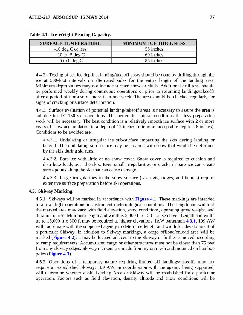
AFI13-217_AFSOCSUP 15 MAY 2014 77
Table 4.1. Ice Weight Bearing Capacity.
SURFACE TEMPERATURE MINIMUM ICE THICKNESS
-10 deg C or less 55 inches
-10 to -5 deg C 60 inches
-5 to 0 deg C 85 inches
4.4.2. Testing of sea ice depth at landing/takeoff areas should be done by drilling through the
ice at 500-foot intervals on alternated sides for the entire length of the landing area.
Minimum depth values may not include surface snow or slush. Additional drill tests should
be performed weekly during continuous operations or prior to resuming landings/takeoffs
after a period of non-use of more than one week. The area should be checked regularly for
signs of cracking or surface deterioration.
4.4.3. Surface evaluation of potential landing/takeoff areas is necessary to assure the area is
suitable for LC-130 ski operations. The better the natural conditions the less preparation
work will be necessary. The best condition is a relatively smooth ice surface with 2 or more
years of snow accumulation to a depth of 12 inches (minimum acceptable depth is 6 inches).
Conditions to be avoided are:
4.4.3.1. Undulating or irregular ice sub-surface impacting the skis during landing or
takeoff. The undulating sub-surface may be covered with snow that would be deformed
by the skis during ski runs.
4.4.3.2. Bare ice with little or no snow cover. Snow cover is required to cushion and
distribute loads over the skis. Even small irregularities or cracks in bare ice can create
stress points along the ski that can cause damage.
4.4.3.3. Large irregularities in the snow surface (sastrugis, ridges, and humps) require
extensive surface preparation before ski operations.
4.5. Skiway Marking.
4.5.1. Skiways will be marked in accordance with Figure 4.1. These markings are intended
to allow flight operations in instrument meteorological conditions. The length and width of
the marked area may vary with field elevation, snow conditions, operating gross weight, and
duration of use. Minimum length and width is 5,000 ft x 150 ft at sea level. Length and width
up to 15,000 ft x 300 ft may be required at higher elevations. IAW paragraph 4.3.1, 109 AW
will coordinate with the supported agency to determine length and width for development of
a particular Skiway. In addition to Skiway markings, a cargo offload/onload area will be
marked (Figure 4.2). It may be located adjacent to the Skiway or further removed according
to camp requirements. Accumulated cargo or other structures must not be closer than 75 feet
from any skiway edges. Skiway markers are made from nylon mesh and mounted on bamboo
poles (Figure 4.3).
4.5.2. Operations of a temporary nature requiring limited ski landings/takeoffs may not
require an established Skiway. 109 AW, in coordination with the agency being supported,
will determine whether a Ski Landing Area or Skiway will be established for a particular
operation. Factors such as field elevation, density altitude and snow conditions will be
78 AFI13-217_AFSOCSUP 15 MAY 2014
considered to determine minimum length and width of the Ski Landing Area. A Ski Landing
Area will not be less than 5,000 ft x 150 ft. Ski Landing Areas shall be marked as shown in
Figure 4.4. The primary differences between Skiways and Ski Landing Areas are the
absence of lead-in flags and, for a Ski Landing Area, fewer skiway flags. A midpoint marker
will be established by placing red flags at the halfway point (five flags for a Skiway, three
flags for a Ski Landing Area).
4.6. Surface Preparation and Maintenance. The agency being supported is responsible for
preparing the surface.
4.6.1. Arctic / Antarctica (other than sea ice) operations on Open Snow, Ski Landing Areas
and Ski-ways will be authorized by the Deployed Commander in accordance with AFI 11-
2C-130, Volume 3, C-130 Operations Procedures, and this Instruction.
4.6.1.1. Dragging is required to remove surface irregularities created by wind action
(sastrugis) and to promote ice crystal deformation to harden the loose surface snow.
Various types of drag devices have been successfully used.
4.6.1.2. The cargo offload/onload area (Figure 4.2) should also be groomed to harden
the surface prior to supporting cargo offload/onload operations.
4.6.1.3. Maintaining the Skiway or Ski Landing Area will require periodic dragging. The
Skiway or Ski Landing Area should be dragged immediately after fresh snow
accumulation, windstorms or when ski landings/takeoffs have disturbed the surface.
Regular inspections by the ground party and pilot reports will determine if dragging or
other maintenance action is required.
4.6.2. Glacial/Sea Ice Ski Landing Areas must be certified by a SLACO and authorized by
the Deployed Commander.
4.6.2.1. Ice irregularities, often hidden by snow cover can do significant damage to skis
when struck at any speed. An ice crack with an edge of more than 4 inches may do
damage at taxi speeds as the ski bridges the crack and a stress point is applied to the ski.
Surface preparation must include a thorough survey of the landing area to look for ice
irregularities and study snow depths and characteristics. Any unacceptable irregularities
must be removed. If the resulting surface is acceptable, ski operations can begin after
appropriate marking and certification. Snow irregularities may be large enough to require
the entire surface to be dragged or graded to fill low areas and remove high areas. All
undulating surfaces must be graded to minimize the slope and prevent ski damage. Care
must be taken not to remove the entire snow surface down to bare ice because snow
cushions and distributes loads during ski takeoffs and landings.
4.6.2.2. Cargo offload/onload areas and taxi routes to those areas should be groomed and
marked as illustrated in Figure 4.2.
4.6.2.3. Weather and repeated ski operations can deteriorate Skiway surface conditions.
Daily inspections by the ground party and pilot reports will determine maintenance
requirements. Daily dragging or grading may be required to maintain an acceptable
surface. Maintenance of flags and the cargo on/offload area are also required.
AFI13-217_AFSOCSUP 15 MAY 2014 79
4.7. Flagging Guidance.
4.7.1. Minimum flagging for a Skiway should consist of the following (Figure 4.1).
4.7.1.1. Lead-in Flags.
4.7.1.1.1. A set of four (4) black flags arranged to make a “plus sign” (+) at each
lead-in flag location.
4.7.1.1.2. The first set of lead-in flags is located 1,000 ft from the skiway threshold
along the extended skiway centerline.
4.7.1.1.3. The second set of lead-in flags will be spaced 500 ft from the first set.
4.7.1.1.4. The third set of lead-in flags will be spaced 500 ft from the second set.
4.7.1.1.5. All other sets of lead-in flags will be spaced 1,000 ft apart out to 12,000 ft
from the skiway threshold to form a two-mile lead-in.
4.7.1.1.6. This spacing will require thirteen (13) sets of lead-in flags.
4.7.1.2. Skiway Flags.
4.7.1.2.1. Three (3) black flags at 400-foot intervals along the full length and on both
sides of the skiway.
4.7.1.2.2. Five (5) red flags at the threshold, midpoint, and departure end locations on
both sides of the skiway.
4.7.1.2.3. Three (3) “2,000 ft remaining” flags (black with a white number 2) on both
sides of the skiway at the appropriate distance remaining from each skiway departure
end.
4.7.2. Minimum flagging for a Ski Landing Area should consist of the following (Figure
4.4).
4.7.2.1. Skiway Flags.
4.7.2.1.1. Two (2) black flags along the full length of both sides of the ski landing
area at 500-foot intervals.
4.7.2.1.2. Three (3) red flags on both sides of the ski landing area at the threshold,
midpoint, and departure end locations.
4.7.2.1.3. Two (2) “2,000 ft remaining” flags (black with a white number 2) on both
sides of the ski landing area at the appropriate distance remaining from each
departure end.
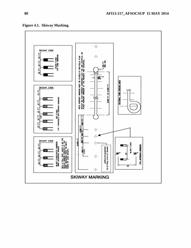
80 AFI13-217_AFSOCSUP 15 MAY 2014
Figure 4.1. Skiway Marking.
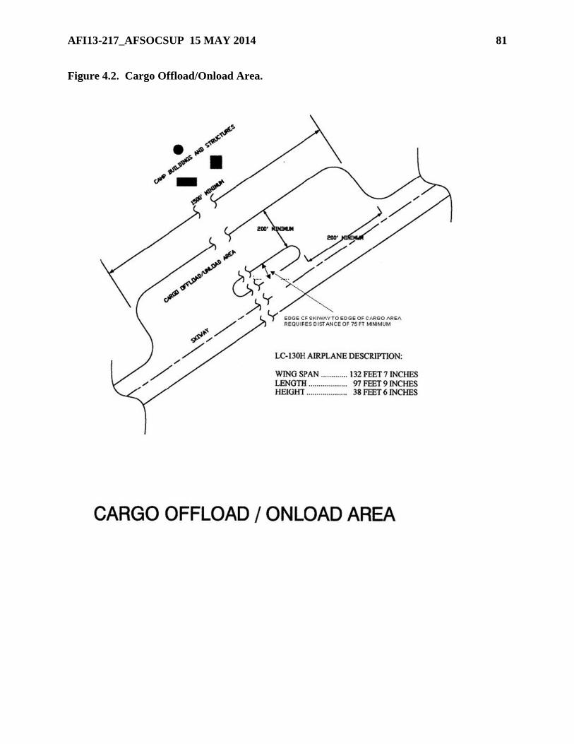
AFI13-217_AFSOCSUP 15 MAY 2014 81
Figure 4.2. Cargo Offload/Onload Area.
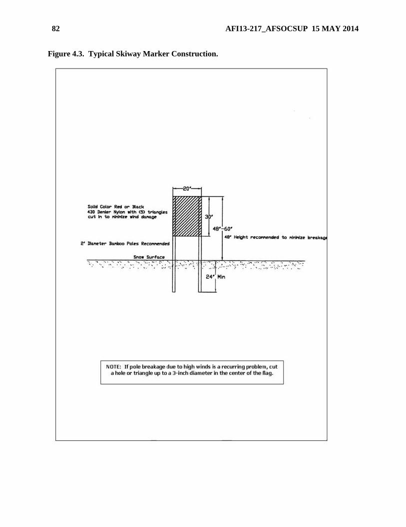
82 AFI13-217_AFSOCSUP 15 MAY 2014
Figure 4.3. Typical Skiway Marker Construction.
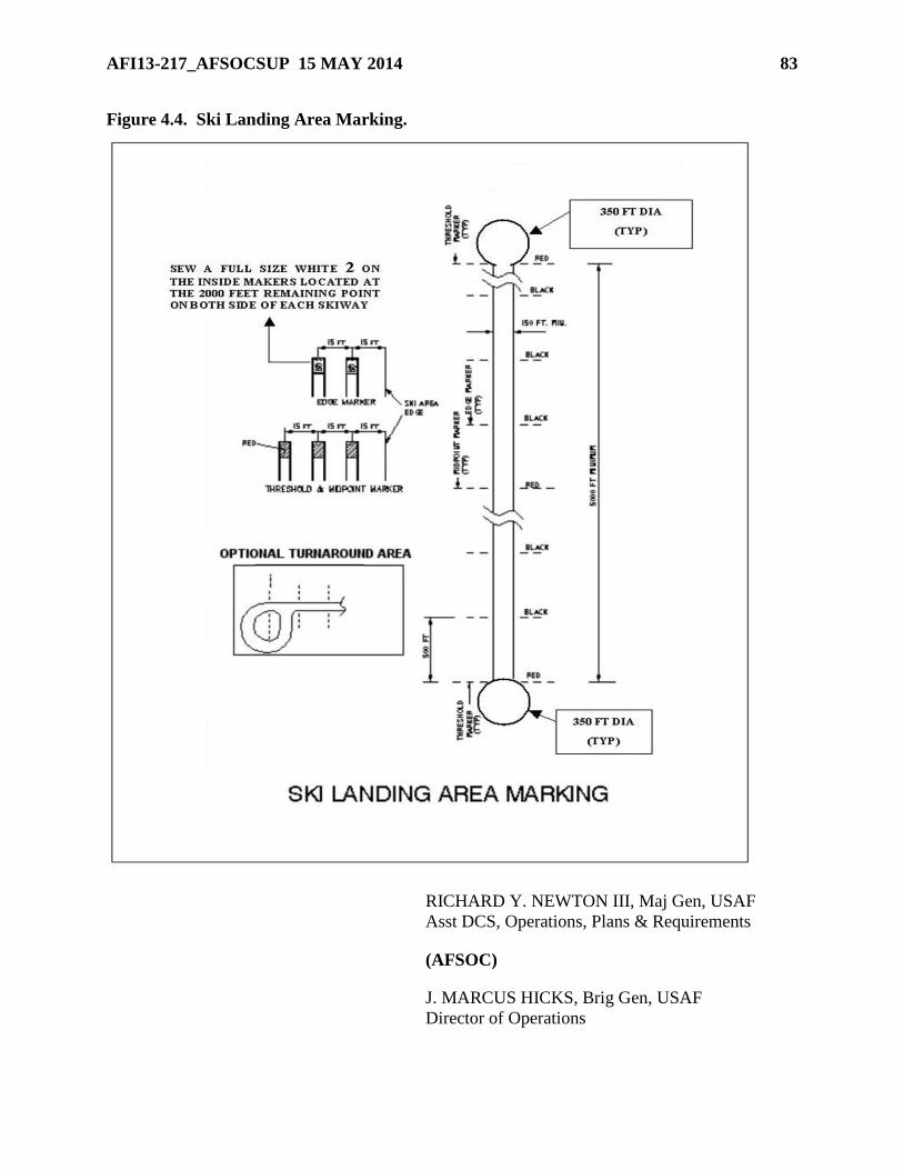
AFI13-217_AFSOCSUP 15 MAY 2014 83
Figure 4.4. Ski Landing Area Marking.
RICHARD Y. NEWTON III, Maj Gen, USAF
Asst DCS, Operations, Plans & Requirements
(AFSOC)
J. MARCUS HICKS, Brig Gen, USAF
Director of Operations
84 AFI13-217_AFSOCSUP 15 MAY 2014
Attachment 1
GLOSSARY OF REFERENCES AND SUPPORTING INFORMATION
References
AFPD 13-2, Air Traffic Control, Airspace, Airfield, and Range Management, 7 January 1994
AFI 11-202 Volume 3, General Flight Rules, 5 April 3006
AFI 11-231, Computed Air Release Point Procedures, 31 August 2005
AFI 11-2C-130, Volume 3, C-130 Operations Procedures, 14 March 2006
AFI 11-410, Personnel Parachute Operations, 20 May 2004
AFI 13-210(I), Joint Airdrop Inspection Records, Malfunction Investigations, and Activity
Reporting, 1 May 1998
AFI 32-7061, The Environmental Impact Analysis Process, 12 March 2003
AFI 91-204, Safety Investigations and Reports, 14 February 2006
AFJPAM 32-8013, Volume II (FM 5-430-00-2), Planning and Design of Roads, Airfields and
Heliports in the Theater of Operations - Airfield and Heliport Design, 19 August 2004
AFMAN 11-411(I), Military Free-Fall Parachuting, 6 April 2005
AFMAN 11-420(I), Static Line Parachuting Techniques and Training, 23 September 2003
(Added-AFSOC) AFMAN 33-363, Management of Records, 01 March 2008
AFMAN 37-123, Management of Records, 31 August 1994
AIR STD 44/35G, Drop Zones and Extraction Zones: Criteria, Markings and Information Check
Lists, 30 April 1990
AIR STD 44/37C, Criteria for Selection and Marking of Landing Zones for Fixed Wing Aircraft,
23 July 1987
AMCI 11-208, Tanker/Airlift Operations, 1 June 2000
AMCI 13-101, Air Mobility Liaison Officers, 30 March 2003
ETL 04-7, C-130 and C-17 Contingency and Training Airfield Dimensional Criteria, 29 March
2004
ETL 02-19, Airfield Pavement Evaluation, Standards and Procedures, 11 December 2002
STANAG 3146, Planning Procedures for Tactical Air Transport Operations, 10 July 1995
STANAG 3345, Data/Forms for Planning Air Movements, 28 February 1989
STANAG 3570, Drop Zones and Extraction Zones, and 3601, Criteria for Selection and
Marking of Landing Zones for Fixed-Wing Transport Aircraft, 28 February 1989
Vaudrey K.D., U.S. Naval Civil Engineering Lab, Technical Report R860, Ice Engineering:
Study of Related Properties of Floating Sea-Ice Sheets and Summary of Elastic and Visco-Elastic
Analyses, 1977
AFI13-217_AFSOCSUP 15 MAY 2014 85
(Added-AFSOC) Prescribed Forms
(Added-AFSOC) There are no prescribed forms in this document.
(Added-AFSOC) Adopted Forms
(Added-AFSOC) AF Form 3822, Landing Zone Survey
(Added-AFSOC) AF Form 4303,Helicopter Landing Zone Survey
(Added-AFSOC) AF Form 847, Recommendation for Change of Publication
Abbreviations and Acronyms
(Added-AFSOC) AC—Asphalt
ACC—Air Component Commander
(Added-AFSOC) ACN—Airplane Classification Number
(Added-AFSOC) ADRP—Aerial Delivery Review Panel
AFCESA—Air Force Civil Engineer Support Agency
(Added-AFSOC) AFM—Aircraft Flight Manual
(Added-AFSOC) AFMAN—Air Force Manual
(Added-AFSOC) AFRC—Air Force Reserve Command
AFRIMS—Air Force Records Information Management System
(AFSOC) AFRIMS—Air Force Records Information Management System
(Added-AFSOC) AFSOC—Air Force Special Operations Command
AFWA—Air Force Weather Agency
AGL—Above Ground Level
AGU—Airborne Guidance Unit
AIE—Alternate Insertion/Extraction
(Added-AFSOC) AMC—Air Mobility Command
AMD—Air Mobility Division
AMLO—Air Mobility Liaison Officer
AMP—Airfield Marking Pattern
(Added-AFSOC) ANG—Air National Guard
AOC—Air Operations Center
(Added-AFSOC) APZ—Accident Potential Zones
ARC—Advanced Rescue Craft
ARFF—Aircraft Rescue and Fire Fighting
86 AFI13-217_AFSOCSUP 15 MAY 2014
ASIC—Air and Space Interoperability Council [formerly known as the Air Standardization
Coordinating Committee (ASCC)]
ATC—Air Traffic Control
AWADS—Adverse Weather Aerial Delivery System
CANLS—Contingency Airfield Night Lighting System
CARP—Computed Air Release Point
(Added-AFSOC) CBR—California Bearing Ratio
(Added-AFSOC) CC—Commander
CCT—Combat Control Team (See Special Tactics)
CDA—Collateral Damage Assessment
CDS—Container Delivery System
COMAFSOF—Commander, Air Force Special Operations Forces
COMJSOTF—Commander, Joint Special Operations Task Force
CRRC—Combat Rubber Raiding Craft
CRG—Contingency Response Group
CRL—Container Ramp Load
CRO—Combat Rescue Officer
CRS—Container Release System
(Added-AFSOC) DCP—Dynamic Cone Pentrometer
DIRMOBFOR-Air—Director Of Mobility Forces
DRAS—Dual Row Airdrop System
(Added-AFSOC) DSN—Defense Switched Network
DZ—Drop Zone
DZC—Drop Zone Controller
DZSO—Drop Zone Safety Officer
DZST—Drop Zone Support Team
DZSTL—Drop Zone Support Team Leader
ETL—Engineering Technical Letter
FAA—Federal Aviation Administration
FARP—Forward Arming and Refueling Point
(Added-AFSOC) FLIP—Flight Information Planning
(Added-AFSOC) FOD—Foreign Object Damage
FOM—Figure of Merit
AFI13-217_AFSOCSUP 15 MAY 2014 87
GAR-I—Ground-To-Air Responder/Interrogator
GMRS—Ground Marked Release System
GPS—Global Positioning System
GFR—General Flight Rules
GRADS—Ground Radar Delivery System
(Added-AFSOC) GSR—Glide Slope Ratio
(Added-AFSOC) GZDB—Global Zone-Database
HAARS—High Altitude Airdrop Resupply System
HAHO—High Altitude High Opening Parachute Technique
HALO—High Altitude Low Opening Parachute Technique
HARP—High Altitude Release Point
HE—Heavy Equipment
HLZ—Helicopter Landing Zone
HN—Host Nation
HSLLADS—High Speed Low Level Aerial Delivery System
HVCDS—High Velocity Container Delivery System
(Added-AFSOC) IAW—In Accordance With
ICAO—International Civil Aviation Organization
IFR—Instrument Flight Rules
I-CDS—Improved-Container Delivery System
IMC—Instrument Meteorological Conditions
(Added-AFSOC) IR—Infrared
(Added-AFSOC) JCS—Joint Chief of Staff
JFACC—Joint Force Air Component Commander
JFSOCC—Joint Force Special Operations Component Commander
JMD—Jumpmaster Directed
JPADS—Joint Precision Airdrop System
(Added-AFSOC) JSOAC—Joint Special Operations Air Component
JSOACC—Joint Special Operations Air Component Commander
(Added-AFSOC) JSOTF—Joint Special Operations Task Force
LAR—Launch Acceptability Region
LCADS—Low Cost Aerial Delivery System
88 AFI13-217_AFSOCSUP 15 MAY 2014
(Added-AFSOC) LCN—Load Classification Number
(Added-AFSOC) LTFW—Light Tactical Fixed-Wing
LV—Low Velocity Container Delivery System
LZ—Landing Zone
LZC—Landing Zone Controller
LZSO—Landing Zone Safety Officer
MAF—Missile Alert Facility
MAAS—Mobile Aircraft Arresting System
(Added-AFSOC) MAJCOM—Major Command
MDS—Mission Design Series
MEW—Mean Effective Wind
(Added-AFSOC) MFF—Military Free Fall
MGRS—Military Grid Reference System
MMLS—Mobile Microwave Landing System
MOA—Military Operations Area
MPI—Multiple Points of Impact
MSL—Mean Sea Level
(Added-AFSOC) NGB—National Guard Bureau
NOTAM—Notice To Airmen
NVG—Night Vision Goggle
(Added-AFSOC) OCONUS—Outside the Continental United States
(Added-AFSOC) OG—Operations Group
OPCON—Operational Control
(Added-AFSOC) OPR—Office of Primary Responsibility
PADS-MP—Precision Airdrop System-Mission Planner
(Added-AFSOC) PCC—Portland Cement Concrete
(Added-AFSOC) PCN—Pavement Classification Number
PFPS—Portable Flight Planning Software
PI—Point(s) Of Impact
(Added-AFSOC) POH—Pilot Operating Handbook
RAM—Raised Angle Marker
RCL—Reception Committee Leader
AFI13-217_AFSOCSUP 15 MAY 2014 89
RDS—Records Disposition Schedule
ROZ—Restricted Operating Zones
RPI—Random Points of Impact
SATB—Standard Airdrop Training Bundle
(Added-AFSOC) SIPRNET—Secure Internet Protocol Network
SKE—Station Keeping Equipment
SLACO—Skiway Landing Area Control Officer
(Added-AFSOC) SOCOM—Special Operations Command
(Added-AFSOC) SOG—Special Operations Group
SOLL—Special Operations Low Level ST—Special Tactics
(Added-AFSOC) SOW—Special Operations Wing
(Added-AFSOC) STG—Special Tactics Group
STO—Special Tactics Officer
STS—Special Tactics Squadron
STANAG—Standardization Agreement (NATO)
TACAN—Tactical Air Navigation
TACP—Tactical Air Control Party
TOT—Time On/Over Target
(Added-AFSOC) USEUCOM—United States European Command
VIRS—Verbally Initiated Release System
VFR—Visual Flight Rules
VMC—Visual Meteorological Conditions
WDI—Wind Drift Indicator
(Added-AFSOC) WS—Wing Span
(Added-AFSOC) WT—Wheel Track
ZAR—Zone Availability Report
ZM—Zone Marker
Terms
Air Component Commander—The Commander Air Force Forces or Joint Force Air
Component Commander; Joint Force Special Operations Component Commander or Joint
Special Operations Air Component Commander.
Airlift Coordination Cell—A cell within the air operations center, which plans, coordinates,
manages and executes theater airlift operations in the area of responsibility or joint operations
90 AFI13-217_AFSOCSUP 15 MAY 2014
area. Normally consists of an airlift plans branch, an airlift operations branch, and an airlift
logistics branch. (Joint Pub 1-02)
Air Mobility Element—The air mobility element is an extension of the Air Mobility Command
Tanker Airlift Control Center deployed to a theater when requested by the geographic combatant
commander. It coordinates strategic airlift operations with the theater airlift management system
and collocates with the air operations center whenever possible. (Joint Pub 1-02)
Air Mobility Liaison Officer—An air mobility expert permanently assigned to an Army/Marine
installation to support a specific Army/Marine ground maneuver unit.
Airfield Marking Pattern—A system of designations that differentiate between the various
types of airfield markings.
Class D Airspace—Category of controlled airspace, which generally consists of the area from
the surface to 2,500 feet above ground level surrounding airports with an operational tower.
Separation services are provided to visual flight rules aircraft on a workload-permitting basis.
Class G Airspace—Class G airspace (uncontrolled) is that portion of the airspace that has not
been designated as Class A, Class B, Class D, or Class E airspace.
Direct Air Delivery—The strategic air movement of cargo or personnel from an airlift point of
embarkation to a point as close as practicable to the user’s specified final destination, thereby
minimizing transshipment requirements. Direct air delivery eliminaes the traditional Air Force
two-step strategic and theater airlift transshipment mission mix.
Director of Mobility Forces—The Director of Mobility Forces will normally be a senior officer
who is familiar with the area of responsibility or joint operations area and possesses an extensive
background in airlift operations. When established, the Director of Mobility Forces serves as the
designated agent for all airlift issues in the area of responsibility or joint operations area, and for
other duties as directed. The Director of Mobility Forces exercises coordinating authority
between the airlift coordination cell, the air mobility element, the Tanker Airlift Control Center,
the joint movement center, and the air operations center in order to expedite the resolution of
airlift problems. The Director of Mobility Forces may be sourced from the theater’s
organizations, United States Transportation Command, or United States Joint Forces Command.
Drop Zone Controller—Qualified individual in charge of a drop zone operation who represents
the appropriate commander as provided in the mission directive.
Drop Zone Safety Officer—The appointed representative of the supported forces commander
who is responsible for the safe operation of the drop zone. Specific duties and responsibilities
vary according to the using airborne unit's standard operating procedures.
Drop Zone Support Team—Qualified U.S. Army/Marine Corps team responsible for
supporting drop zone operations in accordance with this publication and memorandum of
agreement.
Drop Zone Support Team Leader—Individual in charge of U.S. Army/Marine Corps drop
zone support team leader.
Ground Marked Release System—A procedure used by ground forces to determine and mark
the release point for an airdrop.
AFI13-217_AFSOCSUP 15 MAY 2014 91
Helicopter Landing Zone—A specified ground area for landing helicopters to embark or
disembark troops and/or cargo. A landing zone may contain one or more landing sites.
Joint Force Air Component Commander—The commander within a unified command,
subordinate unified command, or joint task force responsible to the establishing commander for
making recommendations on the proper employment of assigned, attached, and/or made
available for tasking air forces; planning and coordinating air operations; or accomplishing such
operational missions as may be assigned. The air component commander is given the authority
necessary to accomplish missions and tasks assigned by the establishing commander.
Joint Force Special Operations Component Commander—The commander within a unified
command, subordinate unified command, or joint task force responsible to the establishing
commander for making recommendations on the proper employment of assigned, attached,
and/or made available for tasking special operations forces and assets; planning and coordinating
special operations; or accomplishing such special operational missions as may be assigned. The
joint force special operations component commander is given the authority necessary to
accomplish missions and tasks assigned by the establishing commander.
Joint Special Operations Air Component Commander—The commander within the joint
force special operations command responsible for planning and executing joint special air
operations and for coordinating and deconflicting such operations with conventional nonspecial
operations air activities. The joint special air operations component commander normally will be
the commander with the preponderance of assets and/or greatest ability to plan, coordinate,
allocate, task, control, and support the assigned joint special operations aviation assets. The joint
special operations air component commander may be directly subordinate to the joint force
special operations component commander or to any non-special operations component or joint
force commander as directed.
Landing Zone—A prepared or semi-prepared (unpaved) airfield used to conduct operations in
an airfield environment similar to forward operating locations. Landing Zone runways are
typically shorter and narrower than standard runways. The amount of engineering effort required
to develop a semi-prepared Landing Zone depends on the planned operation, the service life
needed to support these operations, and the existing soil and weather conditions. Semi-prepared
construction/maintenance preparations may range from those sufficient for limited use to those
required for continuous routine operations. Options for surface preparation may include
stabilization, addition of an aggregate course, compaction of in-place soils, or matting. Since
training airfields are constructed for long-term operations, semi-prepared surface structural
requirements are more stringent than for contingency airfields.
Landing Zone Controller—Individual performing air traffic control duties during landing zone
operations.
Landing Zone Safety Officer—Qualified combat controller, officer aircrew, or qualified
civilian contractor personnel in charge of the landing zone operation.
Mean Effective Wind—A theoretical wind of constant velocity and direction, extending from
the surface to a predetermined altitude above the ground.
Military Free Fall—An employment concept encompassing both high altitude low opening and
high altitude high opening techniques of parachuting.
92 AFI13-217_AFSOCSUP 15 MAY 2014
Military Grid Reference System—The Military Grid Reference System is designed for use
with the Universal Transverse Mercator and Universal Polar Stereographic grids.
Night—The time between the end of evening civil twilight and the beginning of morning civil
twilight, as published in the American Air Almanac, converted to local time. (ref AFI 11-202,
Volume 3, General Flight Rules)
Obstruction (or Obstacle)—A natural or man-made object that violates airfield or heliport
clearances, or projects into imaginary airspace surfaces.
Operational Control—Command authority that may be exercised by commanders at any
echelon at or below the level of combatant command. Operational control is inherent in
combatant command (command authority) and may be delegated within the command. When
forces are transferred between combatant commands, the command relationship the gaining
commander will exercise (and the losing commander will relinquish) over these forces must be
specified by the Secretary of Defense. Operational control is the authority to perform those
functions of command over subordinate forces involving organizing and employing commands
and forces, assigning tasks, designating objectives, and giving authoritative direction necessary
to accomplish the mission. Operational control includes authoritative direction over all aspects of
military operations and joint training necessary to accomplish missions assigned to the
command. Operational control should be exercised through the commanders of subordinate
organizations. Normally this authority is exercised through subordinate joint force commanders
and Service and/or functional component commanders. Operational control normally provides
full authority to organize commands and forces and to employ those forces as the commander in
operational control considers necessary to accomplish assigned missions; it does not, in and of
itself, include authoritative direction for logistics or matters of administration, discipline, internal
organization, or unit training.
Point of Impact—The point on the drop zone where the first parachutist or airdropped cargo
item lands or is expected to land.
Raised Angle Marker—A device used to mark the point of impact during airdrops. A triangular
shaped marker constructed of bright orange material, six feet wide at the base (minimum) and six
feet high (minimum), displayed at a 60-degree angle into the direction of flight.
Ram Air Parachute System—US Army equivalent of a High Glide Ratio Parachute.
Release Point—The point over the drop zone where personnel or equipment should exit the drop
aircraft.
Safety Zone—A distance established by agreement between the air mission commander and the
supported forces’ commander subtracted from the DZ trailing edge to reduce the potential for
off-DZ drops. For peacetime personnel airdrops, the safety zone will never be less than 200
yards. Do not compute safety zone distances for airdrops supporting unconventional warfare
forces as defined by the Joint Strategic Capabilities Plane Annex E, or high altitude low
opening/high altitude high opening airdrops.
Ski Landing Area—A designated area for LC-130 ski operations not meeting the criteria for a
Skiway, but marked and maintained in accordance with this instruction
Skiway—A designated area for LC-130 ski operations marked and maintained in accordance
with this instruction. Skiways must have a published instrument or visual approach procedure
AFI13-217_AFSOCSUP 15 MAY 2014 93
and be located near a surface camp with support facilities to include weather reporting, shelter,
first aid, food, communications and grooming on a continual basis.
Skiway Landing Area Control Officer—An experienced LC-130 pilot or combat controller
experienced in LC-130 ski operations responsible for certifying a Skiway Landing Area.
Station Keeping Equipment—An aircraft avionics system used to maintain formation position
in instrument meteorological conditions. When used in conjunction with an adverse aerial
delivery system lead aircraft, instrument meteorological conditions airdrops are possible.
Special Operations Forces—Those active and reserve component forces of the Military
Services designated by the Secretary of Defense and specifically organized, trained, and
equipped to conduct and support special operations.
Special Operations Low Level—C-17 qualified aircrews that support special operations using
non-standard procedures and criteria, including operations using night vision goggles. Air
Mobility Command provides night vision goggle trained C-130 crews capable of using
procedures similar to special operations low-level aircrew.
Special Tactics Team—United States Air Force special operations consisting of combat control,
pararescue, and combat weather personnel who are organized, trained, and equipped to establish
and control the air-ground interface at an airhead in the objective area. Functions include assault
zone reconnaissance and surveillance, establishment, and terminal control; combat search and
rescue; combat casualty care and evacuation staging; special operations terminal attack; and
tactical weather observations and forecasting.
Tactical Air Control Party—A subordinate operational component of a tactical air control
system designed to provide air liaison to land forces and for the control of aircraft.
Trailing Edge of a Drop Zone—Represents the imaginary line extending between the left and
right rear corners of a surveyed drop zone.
Unilateral—Describes an Air Force only operation. A unilateral mission will not be considered
a joint operation merely because the parachutists or loads are from another service. Example: an
Air Force reserve airlift unit conducting training airdrop missions using Army paratroopers or
when Army paratroopers jump with Air Force personnel on an Air Force unit's operation.
Verbally Initiated Release System—A method of positioning aircraft for airdrop by verbal
instruction from the Drop Zone Controller.
Visual Meteorological Conditions—Weather conditions where visual flight rules apply;
expressed in terms of visibility, ceiling height, and aircraft clearance from clouds along the path
of flight. When these criteria do not exist, instrument meteorological conditions prevail and
instrument flight rules must be followed.
Wind Drift Indicator—A 5 to 6 foot length of paper (approximately).
Zone Marker—An electronic NAVAID used by specially equipped aircraft to aid in positioning
over the landing zone, drop zone, or release point.
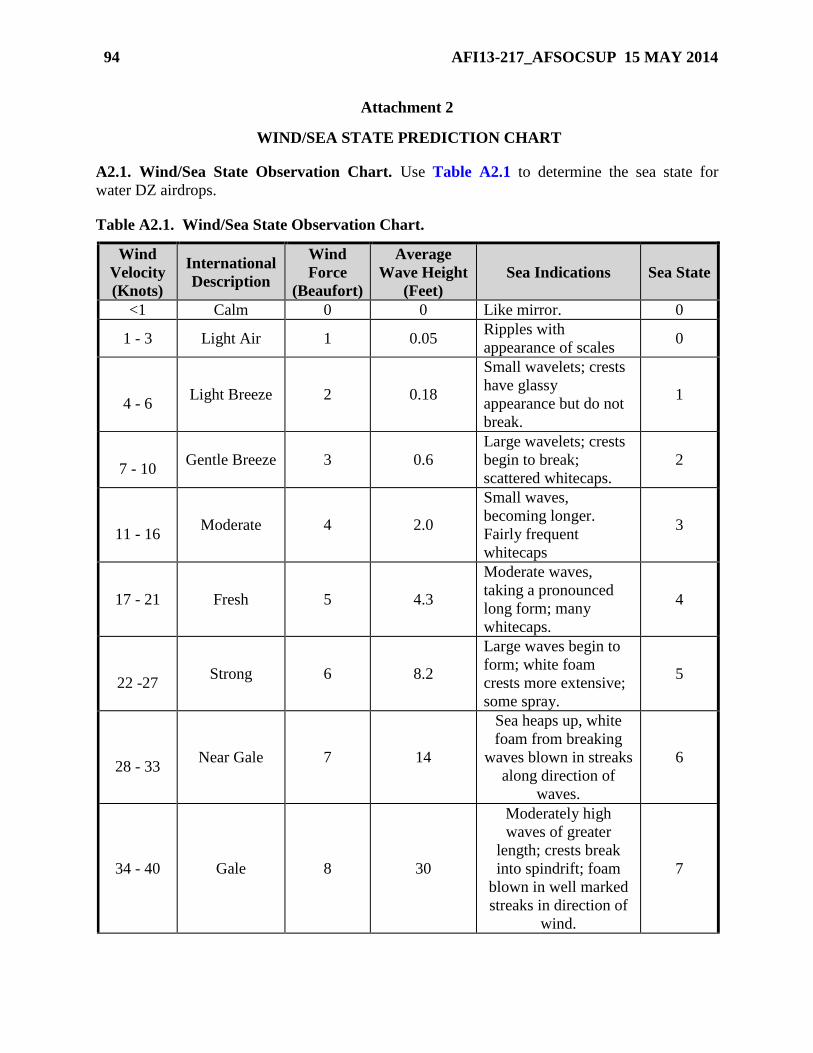
94 AFI13-217_AFSOCSUP 15 MAY 2014
Attachment 2
WIND/SEA STATE PREDICTION CHART
A2.1. Wind/Sea State Observation Chart. Use Table A2.1 to determine the sea state for
water DZ airdrops.
Table A2.1. Wind/Sea State Observation Chart.
Wind
Velocity
(Knots)
International
Description
Wind
Force
(Beaufort)
Average
Wave Height
(Feet)
Sea Indications Sea State
<1 Calm 0 0 Like mirror. 0
1 - 3 Light Air 1 0.05 Ripples with
appearance of scales 0
4 - 6 Light Breeze 2 0.18
Small wavelets; crests
have glassy
appearance but do not
break.
1
7 - 10 Gentle Breeze 3 0.6
Large wavelets; crests
begin to break;
scattered whitecaps.
2
11 - 16 Moderate 4 2.0
Small waves,
becoming longer.
Fairly frequent
whitecaps
3
17 - 21 Fresh 5 4.3
Moderate waves,
taking a pronounced
long form; many
whitecaps.
4
22 -27 Strong 6 8.2
Large waves begin to
form; white foam
crests more extensive;
some spray.
5
28 - 33 Near Gale 7 14
Sea heaps up, white
foam from breaking
waves blown in streaks
along direction of
waves.
6
34 - 40 Gale 8 30
Moderately high
waves of greater
length; crests break
into spindrift; foam
blown in well marked
streaks in direction of
wind.
7
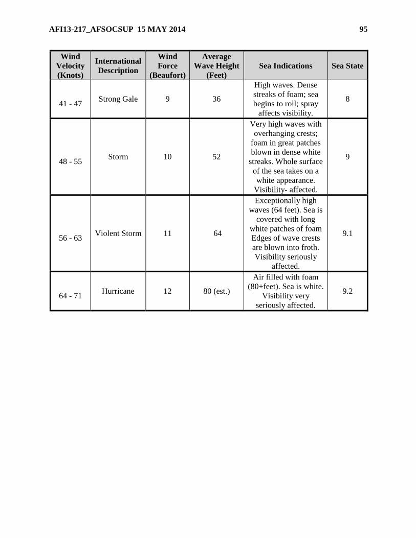
AFI13-217_AFSOCSUP 15 MAY 2014 95
Wind
Velocity
(Knots)
International
Description
Wind
Force
(Beaufort)
Average
Wave Height
(Feet)
Sea Indications Sea State
41 - 47 Strong Gale 9 36
High waves. Dense
streaks of foam; sea
begins to roll; spray
affects visibility.
8
48 - 55 Storm 10 52
Very high waves with
overhanging crests;
foam in great patches
blown in dense white
streaks. Whole surface
of the sea takes on a
white appearance.
Visibility- affected.
9
56 - 63 Violent Storm 11 64
Exceptionally high
waves (64 feet). Sea is
covered with long
white patches of foam
Edges of wave crests
are blown into froth.
Visibility seriously
affected.
9.1
64 - 71 Hurricane 12 80 (est.)
Air filled with foam
(80+feet). Sea is white.
Visibility very
seriously affected.
9.2
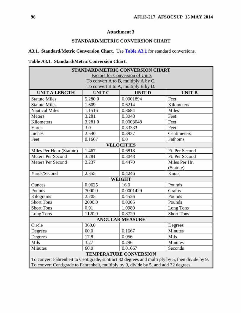
96 AFI13-217_AFSOCSUP 15 MAY 2014
Attachment 3
STANDARD/METRIC CONVERSION CHART
A3.1. Standard/Metric Conversion Chart. Use Table A3.1 for standard conversions.
Table A3.1. Standard/Metric Conversion Chart.
STANDARD/METRIC CONVERSION CHART
Factors for Conversion of Units
To convert A to B, multiply A by C.
To convert B to A, multiply B by D.
UNIT A LENGTH UNIT C UNIT D UNIT B
Statute Miles 5,280.0 0.0001894 Feet
Statute Miles 1.609 0.6214 Kilometers
Nautical Miles 1.1516 0.8684 Miles
Meters 3.281 0.3048 Feet
Kilometers 3,281.0 0.0003048 Feet
Yards 3.0 0.33333 Feet
Inches 2.540 0.3937 Centimeters
Feet 0.1667 6.0 Fathoms
VELOCITIES
Miles Per Hour (Statute) 1.467 0.6818 Ft. Per Second
Meters Per Second 3.281 0.3048 Ft. Per Second
Meters Per Second 2.237 0.4470 Miles Per Hr.
(Statute)
Yards/Second 2.355 0.4246 Knots
WEIGHT
Ounces 0.0625 16.0 Pounds
Pounds 7000.0 0.0001429 Grains
Kilograms 2.205 0.4536 Pounds
Short Tons 2000.0 0.0005 Pounds
Short Tons 0.91 1.0989 Long Tons
Long Tons 1120.0 0.8729 Short Tons
ANGULAR MEASURE
Circle 360.0 Degrees
Degrees 60.0 0.1667 Minutes
Degrees 17.8 0.056 Mils
Mils 3.27 0.296 Minutes
Minutes 60.0 0.01667 Seconds
TEMPERATURE CONVERSION
To convert Fahrenheit to Centigrade, subtract 32 degrees and multi ply by 5, then divide by 9.
To convert Centigrade to Fahrenheit, multiply by 9, divide by 5, and add 32 degrees.
AFI13-217_AFSOCSUP 15 MAY 2014 97
Attachment 4
GUIDANCE CONCERNING AF IMT 3823, DROP ZONE SURVEY
A4.1. AF IMT 3823, Drop Zone Survey. Use these instructions to complete AF IMT 3823.
All blocks require an entry including “N/A” if non-applicable.
A4.1.1. Block 1.
A4.1.1.1. Block 1A. Enter DZ name.
A4.1.1.2. Block 1B. If the survey will be submitted to HQ AMC/A3DT for inclusion in
the ZAR database, then leave blank. If the survey is for local use then the wing/group
tactics office should fill in.
A4.1.2. Block 2.
A4.1.2.1. Block 2A. Enter the Country where the DZ is located.
A4.1.2.2. Block 2B. Enter the state, province, territory, etc.
A4.1.3. Block 3. Enter map series, sheet number, edition, and date of map used.
A4.1.4. Block 4.
A4.1.4.1. Blocks 4A1 through 4A4. Enter the date the original survey was conducted,
surveyor’s name, grade, telephone number, and unit of assignment (include base and
state). The surveyor will sign above their typed name.
A4.1.4.2. Block 4B. The surveyor will fill out this item. Enter approval or disapproval
symbol for each drop category by using the letter “A” for approved, and the letter “D” for
disapproved. Leave no blank spaces under the preprinted categories. The blank column is
for additional special approvals.
A4.1.4.3. Block 4C. The ground operations approval authority will verify and sign.
A4.1.4.4. Block 4D. A safety-of-flight review is completed by the chief, wing/group
tactics, or as assigned by the OG/CC or equivalent, on all DZ surveys. Safety-of-flight
reviewer’s signature gives authority for the aircraft to conduct operations over the DZ.
A4.1.4.5. Block 4E. Once this block is signed, the DZ is ready for use. Signing authority
is the OG/CC or the ACC.
A4.1.4.5.1. If operational requirements dictate, forward the survey to HQ
AMC/A3DT, 402 Scott Drive, Unit 3A1, Scott AFB, IL 62225-5302, to maintain the
most current data in the ZAR database.
A4.1.4.5.2. Group Tactics offices are the local area repositories for DZ surveys.
98 AFI13-217_AFSOCSUP 15 MAY 2014
A4.1.5. Block 5.
A4.1.5.1. Blocks 5A through 5E. Enter the controlling agency responsible for scheduling
the DZ. If the DZ is within a controlled or monitored area, enter the range control data for
that location. If the DZ is not located on government owned property. It may be
necessary to obtain a Land Use Agreement (LUA) or Memorandum of Understanding
(MOU). This is the responsibility of the requesting unit. Check the block that applies and
attach a copy of memorandum if applicable. If the DZ is within a controlled area, enter
the range control data needed for that location.
A4.1.6. Block 6.
A4.1.6.1. Block 6A through 6C. Enter the DZ dimensions using yards and meters. Enter
the DZ radius for a circular DZ.
A4.1.6.2. Blocks 6D through 6F. Enter the distance from the leading edge of the DZ to
each point of impact using yards and meters.
A4.1.7. Blocks 7A through 7D. Enter the primary DZ axis in Magnetic, Grid, and True
North, and include Source and Date of variation data (ensure date of variation data is most
current available). Use the current year when obtaining the information from a GPS. If DZ is
circular, enter N/A. List applicable DZ axis restrictions in remarks.
A4.1.8. Block 8A through 8D. Enter the elevation in mean sea level (MSL) for each point of
impact as well as the highest point on the DZ.
A4.1.9. Block 9.
A4.1.9.1. Block 9A. Enter the spheroid used in computing coordinates for the DZ. This
information can be found on the map legend. If you use the GPS in WGS-84, then enter
the ellipsoid (WGS-84) in this block (recommend using WGS-84 to max extent possible).
A4.1.9.2. Block 9B. Enter the datum used in coordinate computation. This information is
in the legend information on the map. If the GPS is used, enter WGS-84 (recommend
using WGS-84 to max extent possible).
A4.1.9.3. Blocks 9C through 9E. Enter grid zone, Easting, and Northing obtained from
the map.
A4.1.9.4. Block 9F. Place an “X” in the appropriate block.
A4.1.9.5. Block 9G. Enter the grid zone designator, grid square identifier, and the ten-
digit MGRS coordinates. Include a short verbal description of an easily recognized point
on or near the DZ (i.e., road intersection, benchmark, pond, etc.) that can be used by the
DZ party to find the PIs. Include a distance and azimuth from this point to the nearest PI.
Continue the Point of Origin remarks in the Remarks section of the form if necessary.
A4.1.9.6. Block 9H. Enter the ten-digit MGRS coordinates in local datum and spheroid
and the WGS 84 latitude/longitude coordinates to the nearest one-thousandth minute for
each indicated point.
A4.1.9.7. Block 9I. Enter the ten-digit MGRS coordinates in local datum and spheroid
and the WGS 84 latitude/longitude coordinates to the nearest one-thousandth minute for
each corner of the DZ.
AFI13-217_AFSOCSUP 15 MAY 2014 99
A4.1.10. Block 10. Provide a legible sketch or CAD drawing of the DZ including all
obstacles or prominent features located within the DZ boundaries. Include an arrow
indicating magnetic north to assist in sketch orientation. Enter DZ name in space indicated.
A4.1.11. Block 11. Include any pertinent comments regarding operations on the DZ. Also
include any statements concerning safety in the DZ area (i.e., hazards, towers, etc.). Annotate
all charted or observed bodies of water and power lines within 1,000 meters of the DZ
boundaries.
A4.1.12. Block 12. Indicate in the appropriate section whether photographs of the DZ and
approaches are available and whether a low level route is associated with the DZ. Individual
completing the safety-of-flight review should know this information and will mark
accordingly.
NOTE:
When performing a safety-of-flight review on a foreign DZ, as much information as possible
should be filled in on the AF IMT 3823 . At a minimum, the following items must be filled in:
Items 4D, 6A, 6B, 7, 9A-F, and 9H. A copy of the foreign DZ should be attached to the safety-
of-flight review.

100 AFI13-217_AFSOCSUP 15 MAY 2014
Attachment 5
GUIDANCE CONCERNING AF IMT 3822, LANDING ZONE SURVEY
A5.1. AF IMT 3822 . Use these instructions to complete the AF IMT 3822 . All blocks require
an entry including “N/A” if non-applicable.
A5.1.1. Block 1.
A5.1.1.1. Block 1A. Enter LZ name.
A5.1.1.1. (AFSOC) If surveyed using LTFW criteria, place “(LTFW)” after the LZ
name in Block 1A. (T2)
A5.1.1.2. Block 1B. If the survey will be submitted to HQ AMC/A3DT for inclusion in
the ZAR database, then leave blank. If the survey is for local use then the group tactics
office should fill in.
A5.1.2. Block 2.
A5.1.2.1. Block 2A. Enter the Country where the LZ is located.
A5.1.2.2. Block 2B. Enter the state, province, territory, etc.
A5.1.3. Block 3. Enter map series, sheet number, edition, and date of map used.
A5.1.4. Block 4.
A5.1.4.1. Block 4A. Enter the date the original survey was conducted, and surveyor’s
name, grade, telephone number, and unit of assignment. The surveyor will sign on top of
their typed name.
A5.1.4.2. Block 4B. Enter the date the survey was reviewed, reviewer's name, grade,
telephone number, unit and location, and signature. The reviewer is the chief, group
tactics, or as designated by the OG/CC.
A5.1.4.3. Block 4C. Enter the date the survey was approved, or disapproved, and
approver’s name, grade, telephone number, unit of assignment, and signature. The
approval authority is the MAJCOM/DO or ACC.
A5.1.4.3. (AFSOC) Final approval authority is delegated to the OG/CC (Wing/CC for
NGB) or COMAFSOF for landing zone surveys. If OG/CC or COMAFSOF is not an O-
6, approval authority rests with the first O-6 in the operational chain of command.
A5.1.4.3.1. If operational requirements dictate, forward the survey to HQ
AMC/A3DT, 402 Scott Drive, Unit 3A1, Scott AFB, IL 62225-5302, to maintain the
most current data in the ZAR database.
A5.1.4.3.2. Group Tactics offices are the local area repositories for LZ surveys.
A5.1.5. Block 5. Enter the controlling agency responsible for scheduling the LZ. If the LZ is
within a controlled or monitored area, enter the range control data for that location. If the LZ
is not located on government owned property. It may be necessary to obtain a Land Use
Agreement (LUA) or Memorandum of Understanding (MOU). This is the responsibility of
the requesting unit. If the LZ is within a controlled area, enter the range control data needed
for that location.
AFI13-217_AFSOCSUP 15 MAY 2014 101
A5.1.6. Block 6. Self-explanatory. Unit of measure is feet.
A5.1.6. (AFSOC) LZs surveyed for AFSOC LTFW aircraft will have Zone A width listed
in the “SHOULDER” blocks and Zone B width listed in the “GRADED AREA” blocks.
(T-2)
A5.1.7. Blocks 7A through 7D. Enter the primary LZ run-in heading in Magnetic, Grid, and
True North, and include Source and Date of variation data. Use the current year when
obtaining the information from a GPS (ensure date of variation data is most current
available).
A5.1.8. Block 8A through 8C. Enter the elevation in mean sea level (MSL) for each point.
A5.1.9. Block 9.
A5.1.9.1. Block 9A. Enter the spheroid or ellipsoid and datum (e.g., Clark 1866,
NAD1927) use to compute latitude and longitude. If you use the GPS in WGS-84, then
enter the ellipsoid (WGS-84) in this block (recommend using WGS-84 to max extent
possible).
A5.1.9.2. Block 9B. Place an “X” in the appropriate block.
A5.1.9.3. Block 9C through 9E. Enter grid zone, Easting, and Northing obtained from
the map.
A5.1.9.4. Block 9F. Enter the grid zone designator, grid square identifier, and the ten-
digit MGRS coordinates in local datum and spheroid and the WGS-84 latitude and
longitude to the nearest one-thousandth minute for the LZ center point, runway approach
end, and departure end.
A5.1.9.5. Block 9G and 9H. Enter the ten-digit MGRS coordinates in local datum and
spheroid and the WGS 84 latitude and longitude to the nearest one-thousandth minute for
the LZ center point, runway approach end, and departure end.
A5.1.10. Block 10.
A5.1.10.1. Blocks 10A. Enter the type of LZ surface (e.g., clay, asphalt, etc.).
A5.1.10.1. (AFSOC) Surface Block. An example of a normal entry would be Grass or
Dirt. If the surface is Asphalt (AC) or Portland Cement Concrete (PCC) specify the
depth of AC or PCC (e.g., 6" AC or 12" PCC). (T-2)
A5.1.10.2. Block 10B. Enter the soil strength profile. CBR samples should be taken to a
minimum depth of 24-inches for the C-130 and 36-inches for the C-17. Indicate the
thickness and strength of each layer (See ETL 02-19, Airfield Pavement Evaluation,
Standards and Procedures).
http://www.afcesa.af.mil/library/etl.asp?Category=Engineering%20Technical%20Letters.
A5.1.10.2. (AFSOC) Soil Strength Profile Block. An example of a normal entry for a
semi-prepared LZ would be Surface 1" California Bearing Ratio (CBR) 13, Subbase 13"
CBR 25, Subgrade CBR50. If the complete Layer Profile does not fit in the block enter
“See Remarks” and list in the remarks section. (T-2)
A5.1.10.2.1. (Added-AFSOC) CAUTION: Provide a complete soil strength profile
for every LZ; never list a single CBR as controlling. (T-2)
102 AFI13-217_AFSOCSUP 15 MAY 2014
A5.1.10.2.2. (Added-AFSOC) Note: AC/PCC fields will list an airplane
classification number/pavement classification number (ACN/PCN) or load
classification number (LCN) for the field except when very thin pavements are
encountered. In these cases the field may be evaluated as unsurfaced (semi-
prepared), treating the surface as a just a foreign object damage (FOD) sealer. (T-2)
A5.1.10.2.3. (Added-AFSOC) Remarks section will include the following
additional information for runways, taxiways and aprons: Layer Profile, controlling
layer, CBR for controlling layer, number of Dynamic Cone Pentrometer (DCP)
readings taken and depth of the DCP readings. (T2)
A5.1.11. Block 11. Use runway designator noted in item 7A for 11A and 11B
A5.1.11.1. Block 11A. Enter the glideslope ratio used to determine obstacle clearance in
the approach and departure zones.
A5.1.11.2. Block 11B. Enter the percentage of slope for the longitudinal gradient on the
LZ. Use “+” for upslope and “-” for downslope.
A5.1.12. Block 12.
A5.1.12. (AFSOC) LZs surveyed for AFSOC LTFW aircraft will have N/A entered in the
Maintained Area Transverse Section Gradient blocks. The Zone B Transverse Section
Gradient will be entered in the “GRADED AREA” blocks. The Zone A Transverse Section
Gradient will be entered in the “SHOULDER” blocks. (T-2)
A5.1.12.1. Blocks 12A – 12H. Enter percentage of slope for the cross section gradient
areas listed. Use “+” for upslope and “-” for downslope.
A5.1.12.2. Block 12I. Enter any obstacle penetrations.
A5.1.13. Block 13. Provide a legible sketch or CAD drawing of the LZ including all
obstacles, obstructions, and prominent features located within the LZ boundaries. Annotate
the distance these items are from the LZ in the remarks section or depict on the LZ sketch.
Include an arrow indicating magnetic north.
A5.1.14. Block 14. Include any pertinent comments regarding operations on the LZ to
include detailed and specific remarks indicating abnormalities such as loose soil on the
surface level and penetrating depth to the hard layer below. Also include any statements
concerning safety in the LZ area (i.e., hazards, towers, etc.).
A5.1.15. Block 15. Indicate in the appropriate section whether photographs of the LZ are
available and whether a low level route is associated with the LZ. Individual completing the
safety-of-flight review should know this information and will mark accordingly.
AFI13-217_AFSOCSUP 15 MAY 2014 103
Attachment 6
GUIDANCE CONCERNING AF FORM 4303, HELICOPTER LANDING ZONE
SURVEY
A6.1. AF Form 4303, Helicopter Landing Zone (HLZ) Survey . Use the instructions listed
below to complete AF Form 4303. All blocks require an entry, including “N/A” if non-
applicable.
A6.1.1. Block 1.
A6.1.1.1. Block 1A. Enter HLZ name.
A6.1.1.2. Block 1B. If the survey will be submitted to HQ AMC/A3DT for inclusion in
the ZAR database, then leave blank. If the survey is for local use then the group tactics
office should fill in (or to the office designated by the AFSPC/A3)
A6.1.2. Block 2.
A6.1.2.1. Block 2A. Enter the Country where the LZ is located.
A6.1.2.2. Block 2B. Enter the state, province, territory, etc.
A6.1.3. Block 3. Enter the map series, sheet number, edition, and date of map used.
A6.1.4. Block 4.
A6.1.4.1. Block 4A. Enter the date the original survey was conducted, and surveyor’s
name, grade, telephone number, and unit of assignment. The surveyor will sign above
their typed name.
A6.1.4.2. Block 4B. Enter the date the survey was reviewed, reviewer's name, grade,
telephone number, unit and location, and signature. The reviewer, in order of preference,
is the chief, group tactics, squadron commander, or squadron operations officer (or to the
office designated by the AFSPC/A3).
A6.1.4.3. Block 4C. Enter the date the survey was approved, or disapproved, and
approver’s name, grade, telephone number, unit of assignment, and signature. The
approval authority is the OG/CC or ACC.
A6.1.5. Blocks 5A and 5B. Enter the controlling agency responsible for scheduling the HLZ.
If the HLZ is within a controlled or monitored area, enter the range control data for that
location. If the HLZ is not located on government owned property, it may be necessary to
obtain a Land Use Agreement (LUA) or Memorandum of Understanding (MOU). This is the
responsibility of the requesting unit. If applicable, attach the LUA/MOU to the survey when
it is submitted unit or agency responsible for scheduling the HLZ (if applicable).
A6.1.6. Blocks 6A through 6D. Enter the primary HLZ run-in heading in Magnetic, Grid,
True North, and include Source and Date of variation data. Base this heading on the long axis
and or approach/ departure obstructions.
104 AFI13-217_AFSOCSUP 15 MAY 2014
A6.1.7. Block 7.
A6.1.7.1. Block 7A. Enter the spheroid or ellipsoid and datum (Clark 1866, NAD 1927)
used in computing coordinates for the HLZ. This information can be found on the map
legend. If GPS is used, put WGS-84 as the ellipsoid in this block.
A6.1.7.2. Block 7B. Place an “X” in the appropriate box.
A6.1.7.3. Blocks 7C through 7E. Coordinates should be taken from the center point of
the HLZ. Enter grid zone designator and grid square identifier obtained from the map.
A6.1.7.4. Block 7F. Enter the ten-digit MGRS coordinates in local datum and spheroid
and the WGS 84 latitude and longitude to the nearest one-hundredth minute for the HLZ
center point. If computations were done in North American Datum 1927 (NAD-27/NAS-
C), conversions can be accomplished using either the GPS or the MADTRANS
conversion program.
A6.1.8. Block 8.
A6.1.8.1. Block 8A and 8B. Enter dimensions of the HLZ in feet of long axis by short
axis (e.g., 480 x 220 feet). The dimensions of the HLZ describe the portion that has been
surveyed. Areas outside the described HLZ dimensions are not surveyed for landing or
alternate insertion/extraction.
A6.1.8.2. Block 8C. Enter elevation in feet MSL taken from the HLZ center point.
A6.1.8.2.1. (Added-AFSOC) Use the following square dimensions to determine
single-ship HLZs: Non-Dust Out CV-22 = 170' (85' rotor diameter), Dust Out CV-22
= 240' (85' rotor diameter). (T-2)
A6.1.8.3. Block 8D.
A6.1.8.3.1. A minimum of two rotor diameters is required for single-ship training.
Use the following square dimensions to determine single-ship HLZs: MH-53 = 150’
(72’ rotor diameter); UH-1 = 100’ (48’ rotor diameter); CV-22=170’(85’ rotor
diameter); HH-60 = 110’ (54’ rotor diameter).
A6.1.8.3.2. For multiship operations, multiply single-ship dimensions by the number
of aircraft to determine HLZ capacity (e.g., a 4-ship of MH-53s would require a 600
ft x 150 ft long HLZ).
A6.1.8.3.3. For contingency operations use the following dimensions to determine
single-ship HLZs: MH-53 use 125 ft W x 140 ft L; CV-22 use 135 ft W x 110 ft L;
HH-60 use 105’ W x 115’ L. UH-1 use 25-foot clearance from any portion of the
helicopter to the nearest obstacle. For multiship operations, multiply the number of
aircraft by 150 ft W x 150 ft L (i.e., a 4-ship of MH-53s would require a 600 ft W x
150 ft L HLZ).
A6.1.8.4. Block 8E. Annotate obstructions to approach and departure. Use block 9 for
additional space, and illustrate those obstructions in block 10.
AFI13-217_AFSOCSUP 15 MAY 2014 105
A6.1.8.5. Block 8F. Enter degrees of slope based on survey approach axis. Enter upslope
as "+"; enter downslope as "-". Enter the HLZ right slope in the same manner. For
example, a +2 to -.5 degrees HLZ indicates a 2-degree upslope and a negative .5-degree
right downslope on the surveyed approach heading.
A6.1.8.5.1. MH-53 slope limits: 10 degrees nose up, 8 degrees lateral, nose down
slope not recommended.
A6.1.8.5.2. UH-1 slope limits: 10 degrees.
A6.1.8.5.3. CV-22 slope limits: IAW CV-22 Dash 1 (currently 9 degrees in all
direction pending further testing).
A6.1.8.5.3. (AFSOC) CV-22 slope limit: 9 degrees. (T-2)
A6.1.8.5.4. HH-60 slope limits: 6 degrees nose-down, 15 degrees nose-up, 15
degrees left/ right. Aircrew will subtract 2 degrees from each limit for each 5 knots of
wind.
A6.1.9. Block 9. Enter HLZ surface conditions (e.g. grass asphalt, fine dust, etc.). Exercise
extreme care to document the possibility of brown/white out conditions, blowing grass, or
any other flying debris that may restrict visibility or damage aircraft or personnel. Enter other
remarks as required.
A6.1.10. Block 10. Provide detailed diagram of the HLZ. A computer-generated diagram is
desired but not required (See Figure A6.7). At a minimum, display all prominent landmarks
and man-made or natural features that may help identify the HLZ (i.e. roads, rivers,
buildings, etc.). Indicate the recommended approach axis and include an arrow designating
true north. Document and describe all hazards both within the boundaries of the HLZ (e.g.
rocks, tree stumps, holes, depressions, mounds, fences, poles, trees, wires, ditches, etc.) as
well as hazards to the approach (e.g. wires, towers, poles, trees). A remark in bold letters
must be included if the potential for brown/white out conditions exist. Unit HLZs used for
day-to-day training should include aerial photography and/or imagery. Other HLZ surveys
should be supplemented with aerial photography and/or imagery whenever possible.
A6.1.11. Block 11. Annotate if photography is available and attach.
NOTE: When reviewing a foreign HLZ, as much information as possible should be filled in on
the AF Form 4303. At a minimum, the following items must be filled in: Items 4B, 6, 7, and 8. A
copy of the foreign HLZ should be attached to the review.
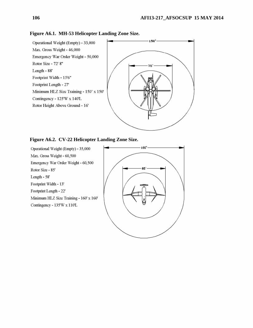
106 AFI13-217_AFSOCSUP 15 MAY 2014
Figure A6.1. MH-53 Helicopter Landing Zone Size.
Figure A6.2. CV-22 Helicopter Landing Zone Size.
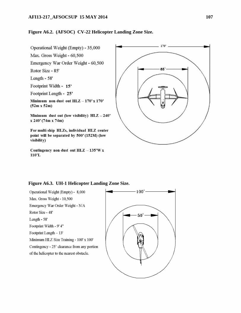
AFI13-217_AFSOCSUP 15 MAY 2014 107
Figure A6.2. (AFSOC) CV-22 Helicopter Landing Zone Size.
Figure A6.3. UH-1 Helicopter Landing Zone Size.
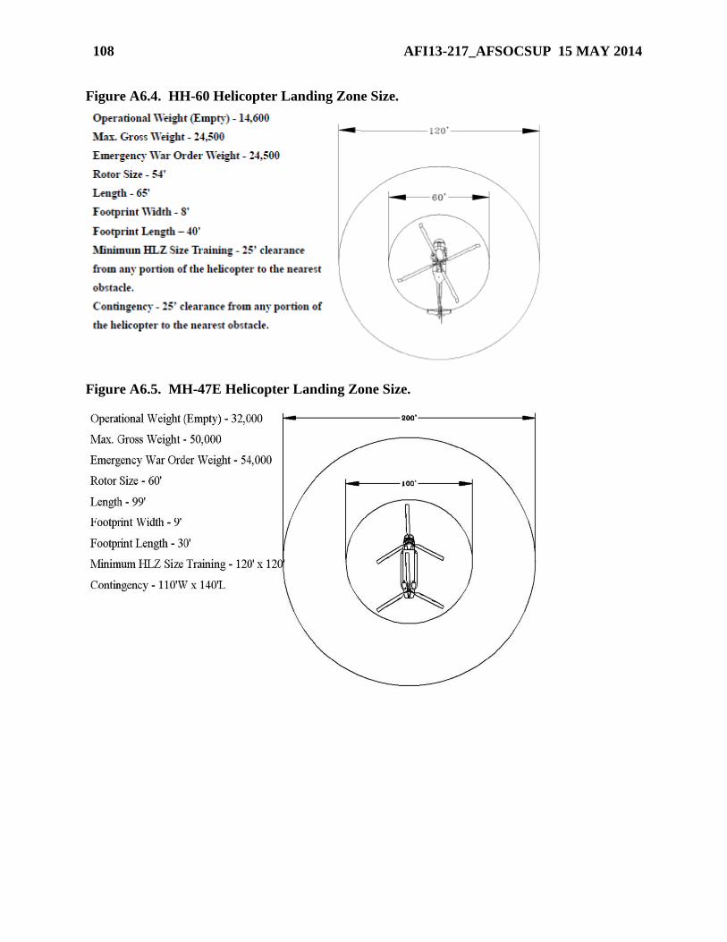
108 AFI13-217_AFSOCSUP 15 MAY 2014
Figure A6.4. HH-60 Helicopter Landing Zone Size.
Figure A6.5. MH-47E Helicopter Landing Zone Size.
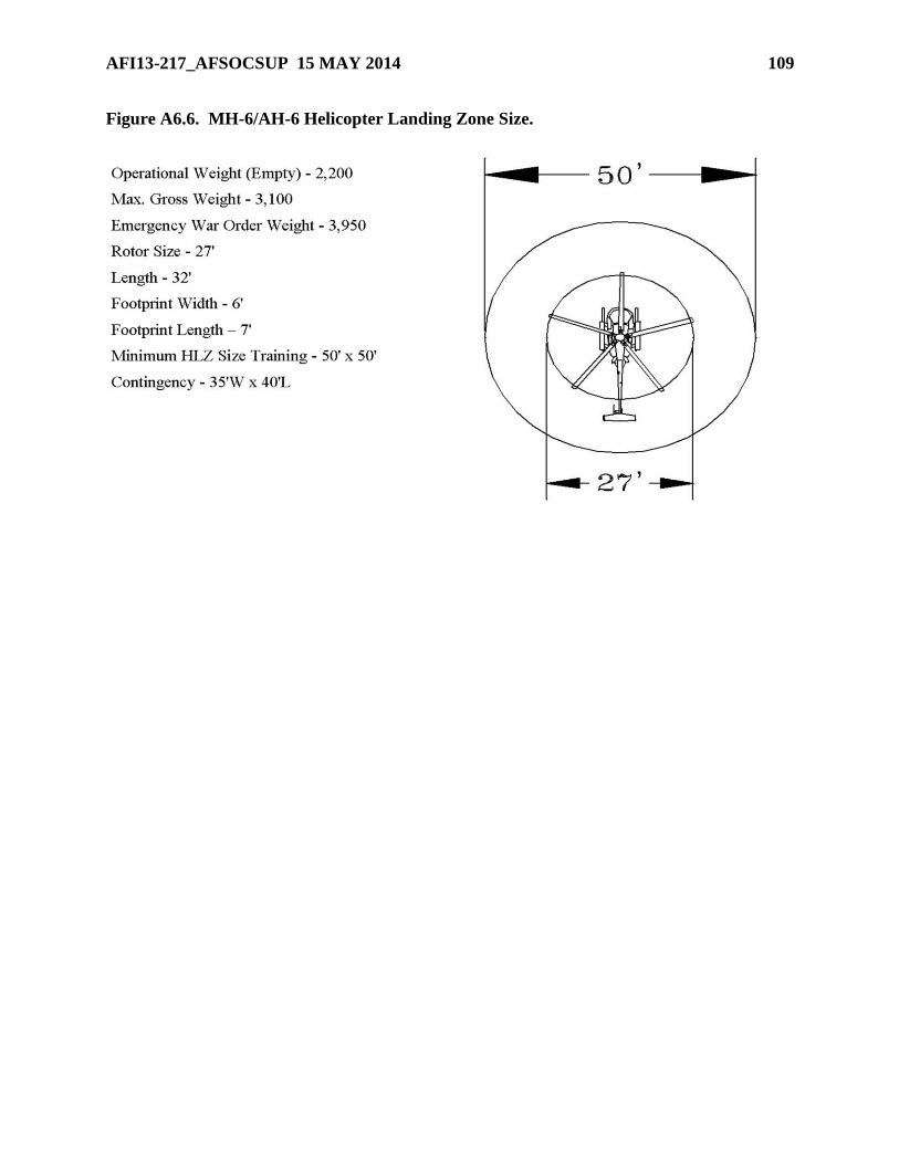
AFI13-217_AFSOCSUP 15 MAY 2014 109
Figure A6.6. MH-6/AH-6 Helicopter Landing Zone Size.
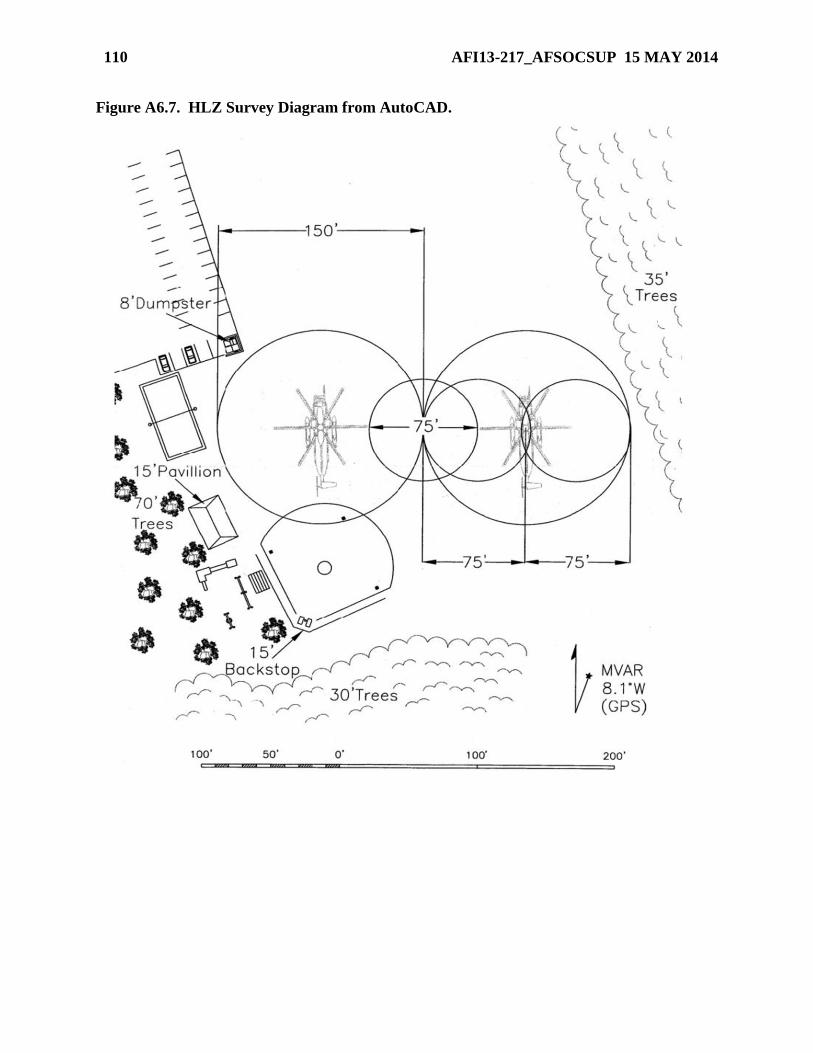
110 AFI13-217_AFSOCSUP 15 MAY 2014
Figure A6.7. HLZ Survey Diagram from AutoCAD.
AFI13-217_AFSOCSUP 15 MAY 2014 111
Attachment 7
GUIDANCE CONCERNING AF FORM 4304, DROP ZONE / LANDING ZONE
CONTROL LOG
A7.1. AF Form 4304, Drop Zone / Landing Zone Control Log. IAW paragraph 2.18.4.4, it is
the responsibility of the DZC to ensure this form is complete and accurate. Group Tactics, or
equivalent, will maintain completed AF Form 4304 IAW AFRIMS.
A7.2. Use the instructions listed below to complete AF Form 4304.
A7.2.1. DATE. Enter date and year. Use either calendar or Julian date. When a “time” is
required use local or GMT consistent with the date.
A7.2.2. LOCATION. Enter DZ name.
A7.2.3. CCT AND UNIT. DZSTL name and unit.
A7.2.4. DZ/LZ CONTROL OFFICER AND UNIT. Self-explanatory.
A7.2.5. DROP ZONE SAFETY OFFICER AND UNIT. Self-explanatory.
A7.2.6. LINE NO. Mission sequence number of each aircraft.
A7.2.7. TYPE ACFT. Mission design series.
A7.2.8. UNIT. Unit of aircraft.
A7.2.9. CALL SIGN. Call sign of lead and, if applicable, formation position number.
A7.2.10. TYPE MSN. Refer to LEGEND for abbreviations.
A7.2.11. ETA. Estimated time of arrival, estimated TOT, or S3 air brief. Keep the unit of
time consistent throughout the form (e.g., local or GMT).
A7.2.12. ATA/ATD. Actual time of every pass or actual time of departure.
A7.2.13. STRIKE REPORT.
A7.2.13.1. YDS. Distance first jumper/container/pallet lands from PI in yards. If within
25 yards it is scored a PI.
A7.2.13.2. CLOCK. Use direction of flight as 12 o’clock and back its azimuth as 6
o’clock, estimate direction from PI to first jumper/container/pallet. If time and conditions
permit, the actual measurement is preferred.
A7.2.14. LZ. Mark the “S” box if a landing occurred between the beginning of the
touchdown zone and the first 500 feet. If the landing was not successful (i.e., go-around),
short of the touchdown zone, or 500 feet beyond the beginning of the touchdown zone, mark
the “U” box and provide comments in the REMARKS box.
A7.2.15. SURF WIND. Surface wind direction in degrees, and velocity in knots.
A7.2.16. SCORE METHOD. Refer to LEGEND for abbreviations.
112 AFI13-217_AFSOCSUP 15 MAY 2014
A7.2.17. MEAN EFFECTIVE WIND. Time taken and at what altitude.
A7.2.17.1. TIME. Self-explanatory.
A7.2.17.2. ALT. Should be drop altitude.
A7.2.17.3. DIR & LVL. Wind direction in degrees and velocity in knots.
A7.2.18. REMARKS. Enter remarks as appropriate.