Embed Size (px)
Citation preview
201 I I 24
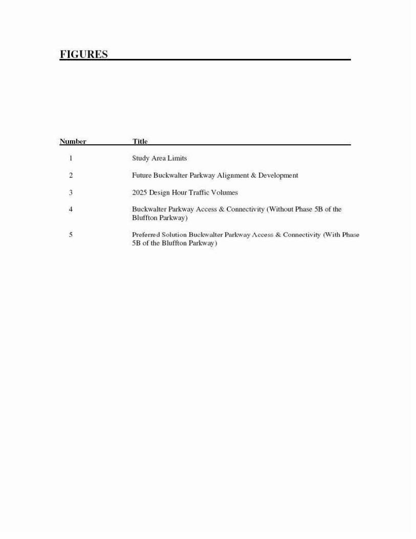
TEXT AMENDMENT TO THE BEAUFORT COUNTY COMPREHENSIVE PLAN.! APPENDIX 10-D. BUCKWALTER PARKWAY ACCESS MANAGEMENT PLAN. WITH A NEW FIGURE 5 THAT ALLOWS THE INSTALLATION OF A TEM PORARY LJGHT AT PARKER DRIVE WHICH MAY BE REMOVED UPON COMPLETION OF PHASE 58 OF THE BUCKWALTER PARKWAY, AND THE MED IAN OPENING AT PARKER DR IVE MAY BE CLOSED UPON COMPLETION OF PI-lASE 5B, AND PHASE 5B ALIGNMENT MAY REMA IN AS IS, AND AS PART OF PHASE 58 CONSTRUCTION, TWO ADDITIONAL RESIDENTIAL ACCESS POINTS MAY BE SIMULTANEOUSLY BUILT TO PROVIDE THREE RESIDENTIAL ACCESS POINTS FOR ADJACENT RESIDENTS.
Ado pted thi s 251h day of July, 20 I I .
UNC IL OF BEAUFORT COUNTY
BY:--~L-,;;__,n__:__. !/_~_//_~--
ATTEST:
c::A.3a.. ~ /LA- n-L ~ Suzanne M. Rainey, Clerk to Counci l
First Reading: May 9. 20 I I Second Reading: May 23, 20 I I and June 13. 20 I I Public Hearing: June 13, 20 II Third and Final Reading: July 25. 20 I I
Wm. Weston J. Newton. Chaim1an
Page I o f' I
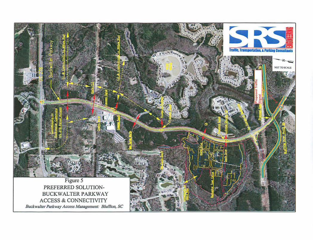
Figure 5 PREFERRED SOLUTION
BUCKWALTER PARKWAY ACCESS & CONNECTIVITY
Buckwalter Parkway Access Management: BluDloo, SC
Appendix 10-D ACCESS MANAGEMENT PLAN: BUCKWALTER PARKWAY
US 278 TO BLUFFTON PARKWAY PHASE 4 BEAUFORT COUNTY, SOUTH CAROLINA
Preoared for:
Beaufort CotJI1ty & Town of Blu(fton
Prepared bv:
,...-: • en
~-~~! ~ . ~~
TraHic, TraasponadDII. & Parting consultallt$
SRSENGINEERING. LLC 801 Mohawk D1ive West Columbia, South Carolina 29 169
SUBMilTED MA¥2007
CONTENTS
INTRODUCTION & PROJECT OVERVIEW............................................................................. 1
Project Overview .................................................................................................................. .
FUTURE CONDITIONS................................................................................................................. 2
Traftic Volume Projections ................................................................................................... 2
TRAFFIC OPERATIONS............................................................................................................... 4
Analysis Scenarios .. .... ......... .... ............ ............. ........ .... ......... .... ............ ............. ........ .... ..... 5
DEVELOPMENT ACCESS/CONNECTIVITY........................................................................... 9
BLUFFTON PARKWAY PHASE 58 DESIGN IMPACTS ......................................................... 12
CONCL USIONS............................................................................................................................... 14
APPEND£X

TABLES
Number Title Page
2025 Daily Traffic Volumes 2
2 Intersection Spacing 6
3 Analyses Results 7
4 Alternative Analyses- Signal at Buck-walter South 8
5 Alternative Anal)•ses- Bluffton Parkway Re-Alignment 13
6 Preten-ed Alternative Bluffton Parkway Re-Alignment IS
7 Bluffton Parkway Current Location Signalized Intersection Spacing IS
FIGURES
Numbe1·
2
3
4
5
Title
Study Area Limits
Future Buck·wa lter Parkway Alignment & Development
2025 Design Hour Traftic Volumes
Buckwalter Parkway Access & Connectivity (Without Phase SB of the Bluffton Park-way)
Preferred Solution Buck'Walter Pnrkwny Access & Connectivity (Wi th Phase 58 of the Bluffton Parkwa)•)
INTRODUCTION & PROJECT OVERVIEW
I NTRODUCTION
SRS Engineeling, LLC (SRS) has been retain~.d by a combination of the Beaufort County Engi neering and the Town of Bluffton Planning Departments to complete an analysis of the nortl1erl)' segn1ent of the Buckwalter Parkway which is both an existing and planned future north/south orientated arterial located in Southern Beau fort Count)'.
As planned b)' the County' s Comprehensive Plan, in it's entire ly, tl1e Bud.-walter Parhvaywill provide a muhilaJJe divided facility betwee n US 278 and SC 46. This facility is anticipated to serve not only north/south orientated u·aftic, but also east/west orientated n·al'fic along the middlelshar<.".d section of the Parbva)' which is current I)' designated as a combined route with the future Bluthon Parkway.
PROJECT OVERVI EW
The segment of tl1e Buch valter Parkway to be studied is tl1e northerly portion of tl1e Pm·kway. In wtal, this segment is approximately 1.6-mi les in length beginning at the signalized intersection with US 278 and ending at the future signalized intersection of the northerly leg of the Blu ffton Par~-wa)' (Phase 4) which is current I)' under construction.
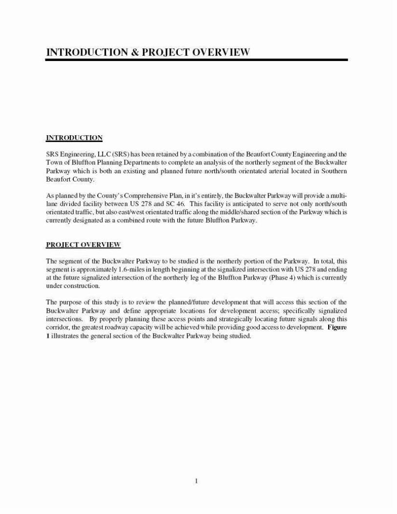
The purpose of this sn1dy is to review the planned/ future deve lopn1ent that will access this section of the Buc~-walter Pm·hvay and define approp1iate locations for development access; specifically signalized intersections. By properly planning these access poi nts and strategically locating future signals along this conidor, tbe greatest roadwa)' Capacity will be achieved while providing good access to developnJent. figu1-e I illustrates the general section of the Buckwalter Parkway being studied.
_ Fording lslar>d Rd~
lj
I = Study Area Corridor
Figure 1
STUDY AREA LIMITS NOT TO
Buck·walter Parkway Access Management: Bluffton, SC
FUTURE CONDITIONS
To estimate the traffic tlow conditions under Future conditions, the County's newly updated transportation mode l has been utilized which reflects the anticipated traffic loading forthe Year2025. Traffic volu mes on the roadway network at l11is time wi ll include all existing traffic, traffic due to normal growth and traJ'tic due to anticipated deve lopment in the area as well as all planned roadway impro,•ements anticipated to be completed as stated in the County's transportation model.
TR'\FFJC VOLUME PRO£ECTIONS
The dai ly traftic volume projections were obtained from the County's Transportation model for the year2025. These future o·affic ' 'olumes were obtained for the two intersections which define the limits of this study, US 278 to tlte nortl1 and tl1e Bltltlton Park:wa)' (northern leg/Phase 4 imersecrion) to rile sourlt. In addition, dai ly two-wa)' tmftic volu mes were also obtained for the segment of the Buckwalter Parkway being studied.
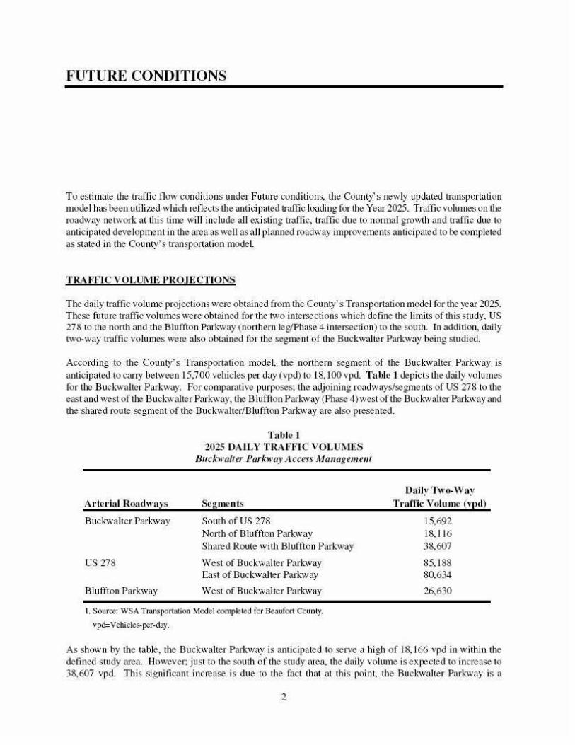
According to the County's Transportation model, the northern segment of the Buckwalter Parkwa)' is anticipated to carry between 15,700 vehicles per day (vpd) to 18, 100 vpd. Table 1 depicts the daily volumes for the Buck-walter Parkwa)'. For comparative purposes; the adjoining roadways/segments of US 278 to the east and west of the Buckwalter Parbva)', the B Ju ftion Park·way (Phase 4) west of the Buck-walter Parhvay and the shared route segment of the Buckwalter/Biuffton Park-way are also presented.
A t'let·ial Roadways
Buck-walter Park-way
US278
Bluffton Parkway
Table 1 2025 DAlLY TR'\FFIC VOLUMES
Buckwalter Pllrkway ;l ccess Management
Sej!ments
South of US 278 North of Bluffton Parkwa)' Shared Route witl1 Bluffton Parkway
West of Buckwalter Parkway East of Buck-walter Park·way
West of Buckwalter Parkway
I. Sourre: WSA Transportation Model completed for Beoufort County.
vpd= Vehicles-per-day.
Daily Two-Way Tt·affic Volume (vpd)
15,692 18, 116 38,607
85, I 88 80,634
26,630
As shown by the table, the Buckwalter Parkway is anticipated to sen•e a high of 18, 166 vpd in within the defined study area. Howe,•er; just to the south of the study area, the daily volume is expected to increase to 38,607 vpd. This signilicant increase is due to the fact that at this point, the Bucl:walter Park-way is a
2
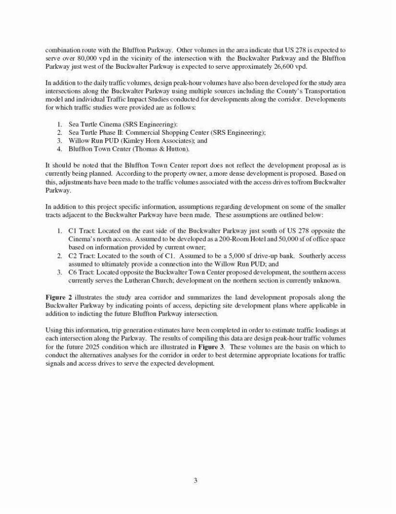
combination route with the Bluffton Parl.-way. Other volumes in the area iodicate that US 278 is expected to serve over 80,000 vpd in the vicinity of the intersection with the Bucl.-walter Parkway and the Blu.ffton Parl.-way just west of the Buck-walter Parkway is expected to sen•e approximately 26,600 vpd.
In addition to the dai I)' o·affic volumes, design peak-hour volumes have also been developed for the study area intersections along Ule Bucl.-walter Parkway using mu ltiple sources including tl1e County's Transportation model and individual Traflic Impact S t11d ies conducted for deve lopments along the conidor. Developnlents for wltich tml'tic swdies were provided are as follows:
I. Sea Turtle Cinema (SRS Engineering): 2. Sea Turtle Phase II: Comnlercial Shopping Center (SRS Engi neering); 3. Willow Run PUD (Kimley Horn Associates); and 4. Bluffton Town Center (Thomas & Hutton).
It should be noted that the Blu l't.ton Town Center report does not reflect the development proposal as is currently being planned. According to the property owner, a more dense development is proposed. Based on this, adj usntlents ha\'e been made to the n·aftic voiUllleS associated wi th the access drives to/from Buckwalter Parl.-wa)'.
In addition to this project specitic information, assumptions regarding de\•elopment on sonle of the smaller tracts adjacent to the Buckwalter Parkway ha,•e been made. These assumptions are outlined below:
I. C J Tract: Located on the east side of the Buckwalter Parkway just south of US 278 opposite the Cinema's north access. Assunled to be developed as a 200-Room Hotel and 50,000 sf of oftice space based on information provided by current owner;
2. C2 Tract: Located to the south of C J. Asslmled to be a 5,000 sf drive-up bank. Southerl)' access assumed to ultimately provide a comlection into the Willow Run PUD; and
3. C6 Tract: Located opposite the Buckwalter Town Center proposed development, the soutllern access currently serves the Lutheran Church; deve lopnle nt on tlle northern section is cUJrently unknown.
Figure 2 illustrates the stud)' area corridor and summarizes tile land development proposals along the Bucl.-walter Parkway by indicating points of access, depicting si te development plans where applicable in addition to indicting the future Bluffton Parkway intersection.
Usi ng this information, trip generation estimates have been completed in order to estimate traffic loadings at each intersection along the Parkway. The results of compiling this data are design peak-hour traffic volumes for tile future 2025 condi tion which are illustrated io Figm·e 3. These \'olumes are the basis on which to conduct the alternatives analyses for the corridor in order to best determine appropriate locations for traftk signals and access drives to serve the expected development.
3
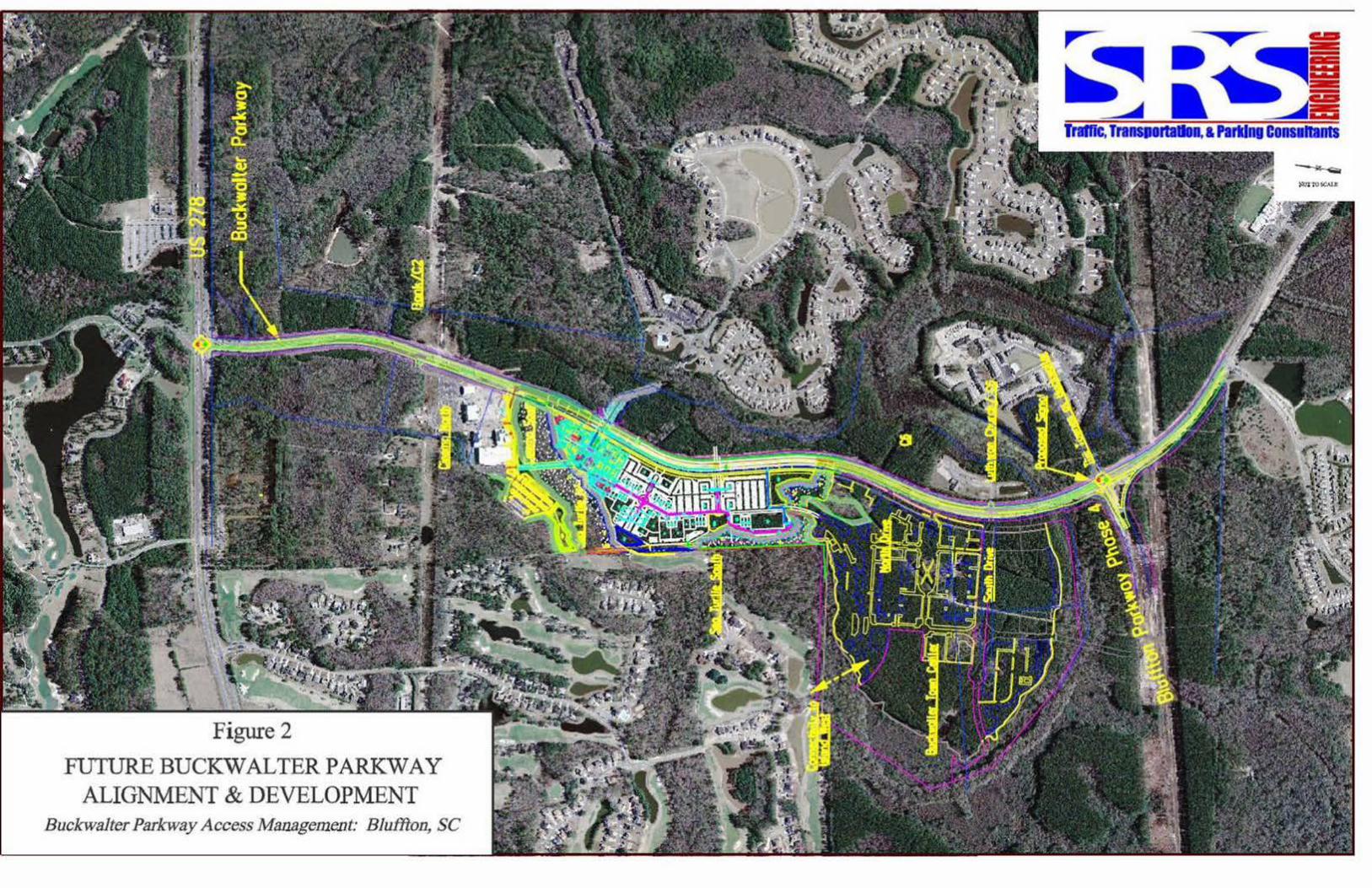
Figure 2
FUTURE BUCKWALTER PARKWAY ALIGNMENT & DEVELOPMENT
Buckwalter Parkway Access Management; Bluffton, SC
:e 0 j "' 13
!t u
i
~ != w ~~ t
~~~ + <SQ ~~~ ~poo
~ 't. B<t'dey lr.ll + S(J:I' ;l( po:!. 1tt +'I~ ~Il90 >0 >0~ ~ j :! ~It+
~ ~
J I ~ ! J jg
~ ~
Figure 3
2025 DESIGN HOUR TRAFFIC VOLUMES
Buckwalter Parkway Access Management
i "" I
~Ul Ho:!.
.& IOJ
~ft+ ~ ~
1 J
i l
~ +'I~
~lfo jp:! ,/:" ~
~tt+ ~
Buckwalter Pkwy. I J
NOTTOSCALE
\ ·~
TRAFFIC OPERATIONS
To assess quality of flow, capacity analyses were conducted to prO\• ide an indication of how well the stud)' area intersections and roadway segments are anticipated to serve future traffic demands. The following provides a desc1i ption of tl1e methodology utilized to complete these analyses.
METHODOLOGY
Level-of-Service
A pdmruy result of capacity analyses is the assignmem of leve l-of-service (LOS) to traftic faci lities under vru·ious traffk flow conditions'. The concept of le\•el-of-service is defmed as a qualitative measure describiog operational conditions within a traffic stream and their perception by motorists ru1eVor passen_gers. A level-of· service definition provides an index to guality of trafllc !'low in terms of such factors as speed, travel time, freedom to maneuver, traffic interruptions, comfort, convenience, and safety.
Six levels-of-service are de tined for each type of facilit)'. They are given Jeuer designations from A to F, widl LOS A represe nting the best operating conditions and LOS F the worst.
Since the level-of-service of a traftic facility is a function of the traffic tlows placed upon it, such a faci lity may operate at a wide range of levels-of-service, depending on the rime of day, day of week, or period of a )eru·.
Signalized Intersect ions
The six levels-of-service for signalized intersections may be desc1ibed as follows:
• LOS A describes operations with very low delay; most vehicles do not stop at all.
• LOS B describes operations wi tl1 re lative ly low delay. However, more vehicles stop than LOS A.
• LOS C descdbes operations with higher de lays. Individual cycle fui lu res may begin to appear. The number of vehicles stopping is significant at this level, although man)• still pass through the intersection without stopping.
• LOS D describes operations with delay in the rru1ge where the influence of congestion becomes more noticeable. Many vehicles stop and indi,•idual cycle failures ru·e noticeable.
• LOS E describes operations with ltigh delay values. Individual cycle fai lures are freguent occurrences.
The capacity analysis methodology is based on the concepts and procedures in the Highway Capacity Manual; Transportation Research Board: Washington, DC; 2000.
4
• LOS F desc1ibes operations with high delay va lues that often occur widl over-saturation. Poor progression and long C)'cle lengths may also be major connibuting causes to such de lay leve ls.
Levels-of-service for signalized intersections are calculated using the operational analysis methodology of the 2000 Highway Capacity Manual. This method assesses the effects of signal type, tinting. phasing, and progression; vehicle nux; and geomenics on delay. Level-of-service designations are based solely on the clite1ion of calculated control de lay per vehicle, since de lay is a measure of dliver discomfort, frustration, fuel consumption, and increased n·avel time.
Roadway Segment A nalyses
The determination of how a roadway segment serves traffic is an investigation of multiple factors including roadway geometry, number of operating Janes, provision of auxi lia1y lanes (left-tum & •ight-tllfn), traffic \'Olumes and directional splits of traffic, access drives per mile, and the separation of signalized intersections. These factors result in an assignment of arterial speed and level of service which is used to assess the roadway operations.
Signalized InteJ-section SJ>acing
The proper spacing of n·affic signals along the Buckwalter Parkway will be critical so that the conidor can provide the greatest/most efticient capacity tJ1at it is capable of provid ing. Without proper spacing. vehicle queues n1a)' be created which back into/through adjace nt inter~ctions resulting in a "grid lock'' pattern which causes a significant degradation in roadway capaci ty and traffic tlow. According to access management gujdelines, the ideal spacing of signalized intersections along a major arterial such as the Buckwalter Par~-way is ideally 2,640-feet or a 1/2-mile (ref. Access Managemem Manual, TRB). This separation provides a progression speed ranging between 30 and 40 miles per hour (mph).
Howe,•er, this spacing ma)' not be achie,•able in all circumstances due to constraints such as topography, environmental issues/wetlands, etc. While the most advantageous separation is 1/2-mile and should be provided if feasible, shorter separation distances of 1,500-l ,700-feet wi ll allow progressions speeds along the Buc~-walter Parkway that are in the 30 mph range.
In planning signal locations, one must also account for the classification of roadways that intersect the corridor. For instance, when interesting a major roadway/arterial which presumably serves a large volume of traffic, separation to the nex t adjacent iotersection(s) is extreme!)' important so tJ1at vehicle speeds and resulting queues/stacking do not interfere with the operations of adjacent traffic signal.
ANALYSIS SCENERJ OS
Review of the Buckwalter Parkway con·idor and the submitted/approved traffic studies begins to identiJ')• logical intersections for installation ofn·atfic signal control which meet signal wru-rants. Two intersections are ob,•iousl)' going to either maintain traftic signal conu·oJ (US 278 at Buckwalter Pru"kway) or w be placed under traftic signal control (future intersection of Blu ffton Parhva)' Phase 4 at Buckwalter Parhva)').
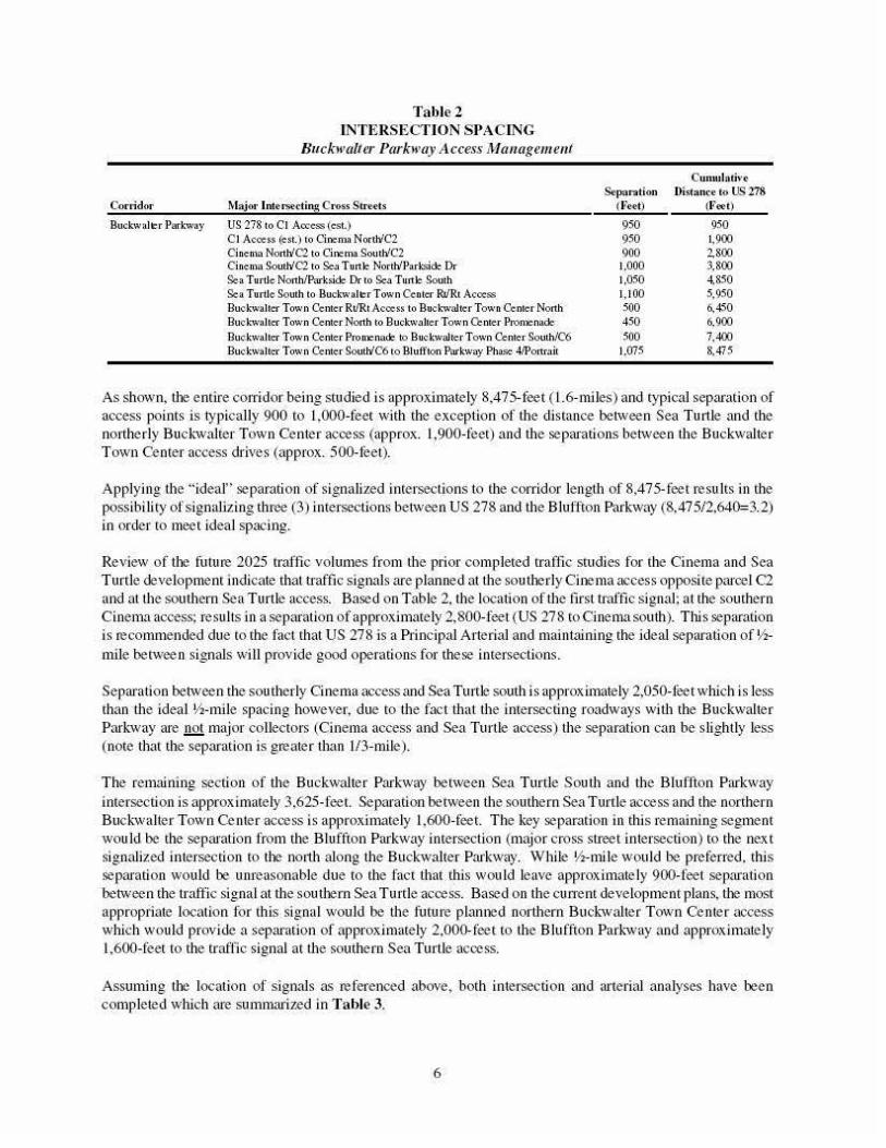
There are multiple intersections located along the Buc~·walter Parkway that are built and/or planned as part of development proposals. Table 2depicts the approximate spacing of intersections along the Pru·kway using US 278 as tl-.e starting point.
5
Corridor
Bucl.."\\•alfl!' r Parl..'""\\•ay
Table 2 INTERSECTION SPACING
Buckwalter Pllrkway ;l ccess Mauagemeut
Ma.iot• lntc rst"ctin.e: Cross Si:fttts
US 278 to CJ Arx:ess (esl ) CJ Acoe.ss (e.st.) to Cinema NorthfC2 Cinema Nonh'Cl to Cine.ma Soutll"C2 Cine.ma South'C2 to Set~ Tunlr: NortWP:~.rksid: Dr Sea Turtle Nonh!Pnrksidr!'. Or to Sc.'l Turtle South Se.a Turtle South to Bud:walterTown Center RriRt Acoess Bu.:- 1..--walter Town Center Rt/Rt Acoess to Bud;walterTown Ce.nter North Buckwalter Town Center North to B uel.."w :~ lte r Town O:.nte r Promenade Buckwalter Town Center Pro me nndC' to B ucJ... .. wnl te r Town Cc.nte r South/C6 Bu.:- 1..--walter Town Center Soutb'C6 to Bluifton Parkway Ph3Se 4/Ponmit
Separation ( F<tt)
950 950 900 1.000 1.050 1.100 500 450 soo
1.075
Cumu1atin Ois1.ancc io US 278
(F«t)
950 1.900 1800 3.800 4.850 5,950 6,450 6.900 7.400 8.475
As shown, Ule entire corridor being studied is approximate!)• 8,475-feet ( 1.6-miles) and typical separation of access points is typicall)• 900 to 1,000-teet with the exception of the cUstance between Sea Turtle and the northerly BucJ.:walter Town Center access (approx. 1,900-teet) and the separations between the Buckwalter Town Center access drives (approx. 500-feet).
Applying the "ideal" separation of signalized intersections to the corridor lengtJ1 of 8,475-feet results in the possibility of signalizing three (3) intersections between US 278 and the Bluffton Parkway (8,47512,640=3.2) in order to meet ideal spacing.
Review of tile fut11re 2025 tcaftic volumes from the p1ior completed traffic studies for the Cinema and Sea Turtle development indicate that traffic signals are planned at the soutllerly Ci tlema access opposite parcel C2 and at the southern Sea Turtle access. Based on Table 2, tl1e location of the first traffic signal; at the southern Cinema access; results in a separation of approximately 2,800-feet (US 278 to Cinema south). This separation is recommended due w the fact that US 278 is a Plincipal Arterial and maintaining the ideal separation of !hmile between signals wi ll provide good operations for these iotersections.
Separation between the southerly Cinema access and Sea Turtle south is approximate!)• 2,050-reet which is less than the ideal !h-mile spacing however, due to the fact that the intersecting roadways wi th the Buckwalter Parkway are .!!.2! major collectors (Cinema access and Sea Turtle access) the separation can be slightly less (note that the separation is greater than 1/3-mile).
The remaining section of the Buckwalter Parkway between Sea Turtle South and the Bluffton Parkwa)' intersection is approx imately 3,625-feet. Separation between the southern Sea Turtle access and the northern Buck'Walter Town Ce nter access is approximately 1.600-feet. The key separation in this remaining segment would be the separation from the Bluffton Parkway intersection (major cross street intersection) to the next signalized intersection to tile nortl1 along the Buckwalter Parkway. While !h-mile would be preferred, this separation would be unreasonable due to the fact tJ1at tltis would lea,•e approximately 900-feet separation between the traffic signal at tl1e soutllern Sea Turtle access. Based on the cun·em development plans, tlle most appropliate location for this signal would be the future plamled northern Buck'Waller Town Center access which would provide a separation of approximately 2,000-feet to the Bluffton Park'Way and approximately 1,600-feet to the traftic signal at the southern Sea Turtle access.
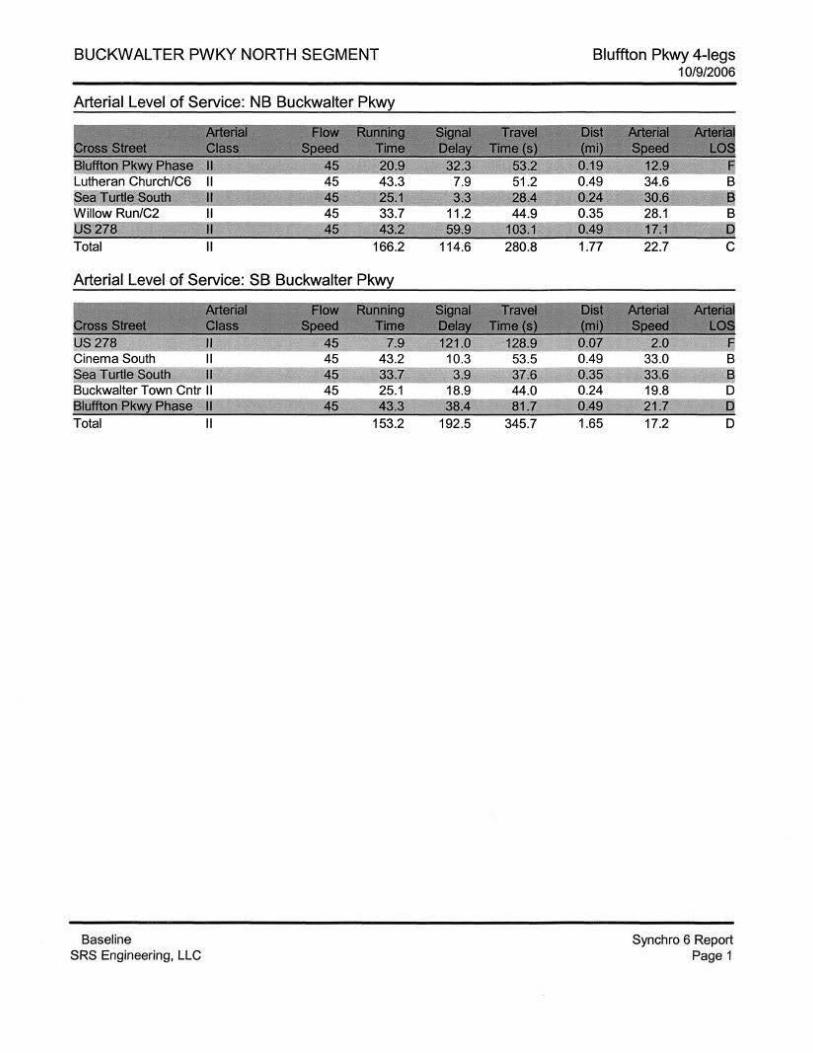
Assuming Ule location of signals as referenced above, both intersection and arterial analyses have been completed which are summarized in Table 3.
6
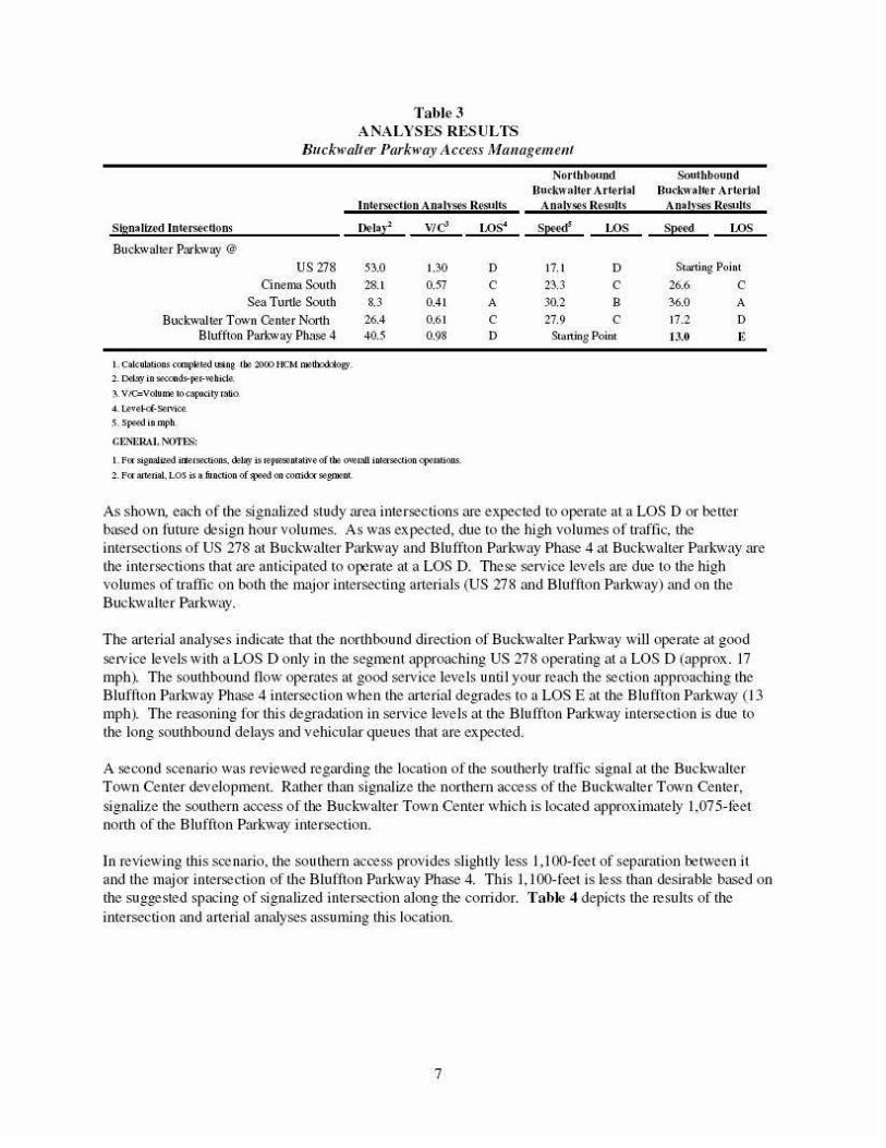
Table3 ANALYSES RESULTS
Buckwalter Parkway Access Mtuwgem.ellt
SIDnaltud ln4'£'S4!-(tlons
Buc.J..·waJter Pnrkway @
US278 a nemaSomh
Sea Tu111e South Buckwalter Town Center No11h
Bluffton Park·way Phase 4
1. Calcubtions cetnp~ted tt9ln~ tilt 2000 HCM rrelb..~o~ .
2. 011:1.'1)' in geooods-pH·'-tbide.
$. VIC=VoJU.IOO tOc.'I!XJCil)' ltlliO.
4 . t..evel-of·~rvica
s. Speed io.nph.
CRNliRAI. i\'OTES:
lntei"S(l.ctlon AnalvS('s Results
~Ia~·: VIC' l.OS4
53.0 1.30 D 28.1 0.57 c 8.3 0.41 A
26.4 0.6 1 c 405 0.98 D
1. F«Sign3111Rd itursections. &lay is repRSilntaUVeof t~ ~mil inwrse.:tion opemtions. 2. Pocanerilll .. LOS is a. function of :t.wd on oonid..-.-~t,~nent.
Northbound Southbound Bucl.:waltt'r Arterial Buc:J..'W~It(>r Arterial
Analvses Resu!ls AnalvSt\S Results
SP"¢ l.OS Sp«d 1.05
17.1 D Starting Point 23.3 c 26.6 c 30.2 B 36.0 A
27.9 c 17.2 D Starting Point 13.0 E
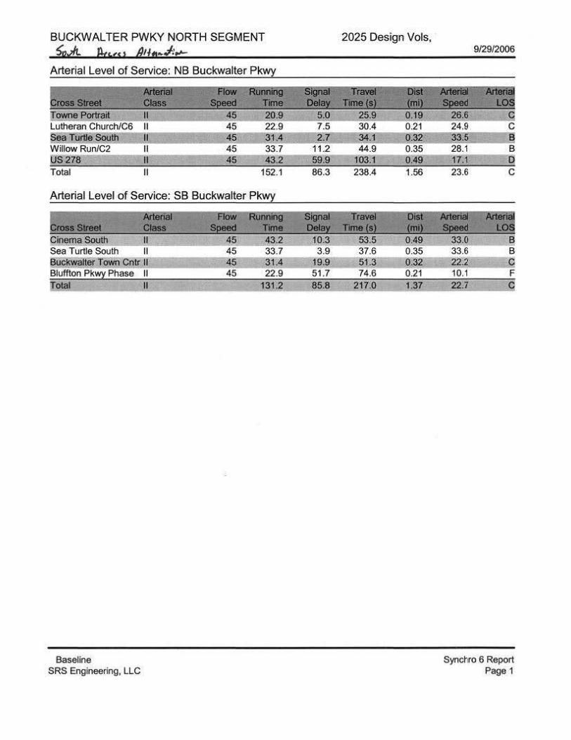
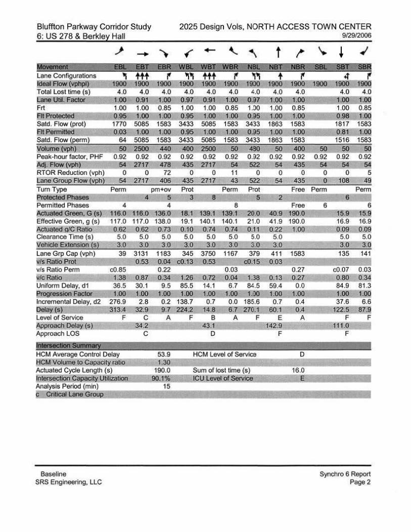
As shown, each of the signalized stttd)' area intersections are expected to operate at a LOS D or better based on future design hour volumes. As was expected, due to the high volumes of u·atlic, the intersections of US 278 at Buckwalter P:ul-wa)' and Blulh oo Parl-wa)' Phase 4 at Buckwalter Parkwa)' are the intersections that are anticipated to operate at a LOS D. These service levels are due to the high volumes of trafllc on both the major intersecting artelials (US 278 and Bluffton Parkwa)') and on the Buck-walter Parkway.
The arterial analyses indicate that the northbound direction of Buckwalter Parkwa)' wi ll operate at good service levels with a LOS D onl)' in the segment approaching US 278 operating at a LOS D (approx. 17 mph). The southbound tlow operates at good service levels until your reach the section approaching the Bluffton Parkwa)' Phase 4 intersection when the artelial degrades to a LOSE at the Blu ffton Parkwa)' ( 13 mph). The reasoning for this degradation in service leve ls at the Blulf ton Parkway intersection is due to the long southbound delays and vehicular gueues ll1at are expected.
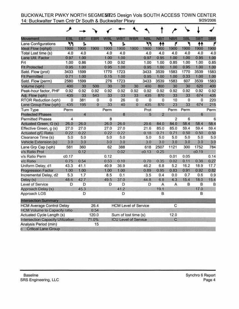
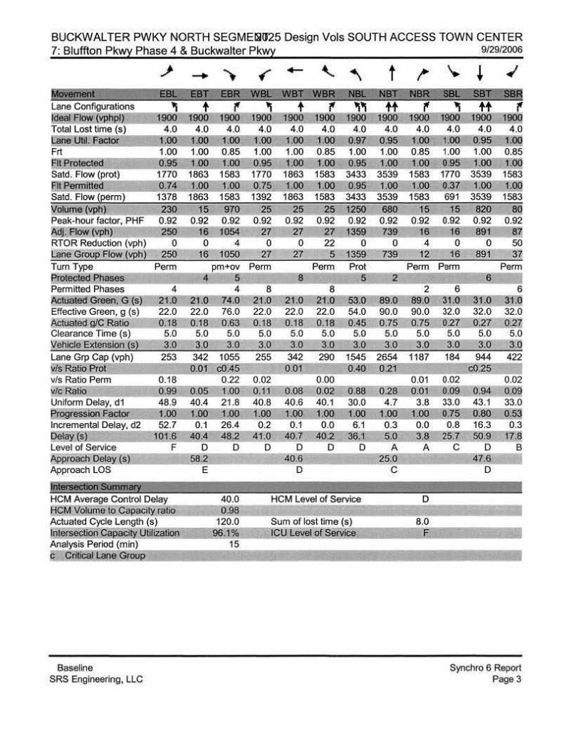
A second scenario was reviewed regarding the location of the southerly traftic signal at the Buch valter Town Center development. Rather than signalize the northern access of the Buckwalter Town Center, signalize the southern access of the Buck-walter Town Center which is located approximate!)' 1,075-feet north of the Blu ffton Parkwa)' intersection.
In re\•iewing this scenario, the southern access provides slightly less I , I 00-feet of separation between it and the major intersection of the Bluffton Park-wa)' Phase 4. This 1, 100-feet is less than desirable based on the suggested spacing of signalized intersection along the corridor. Table 4 depicts the results of the intersection and artelial anal)'ses assuming this location.
7
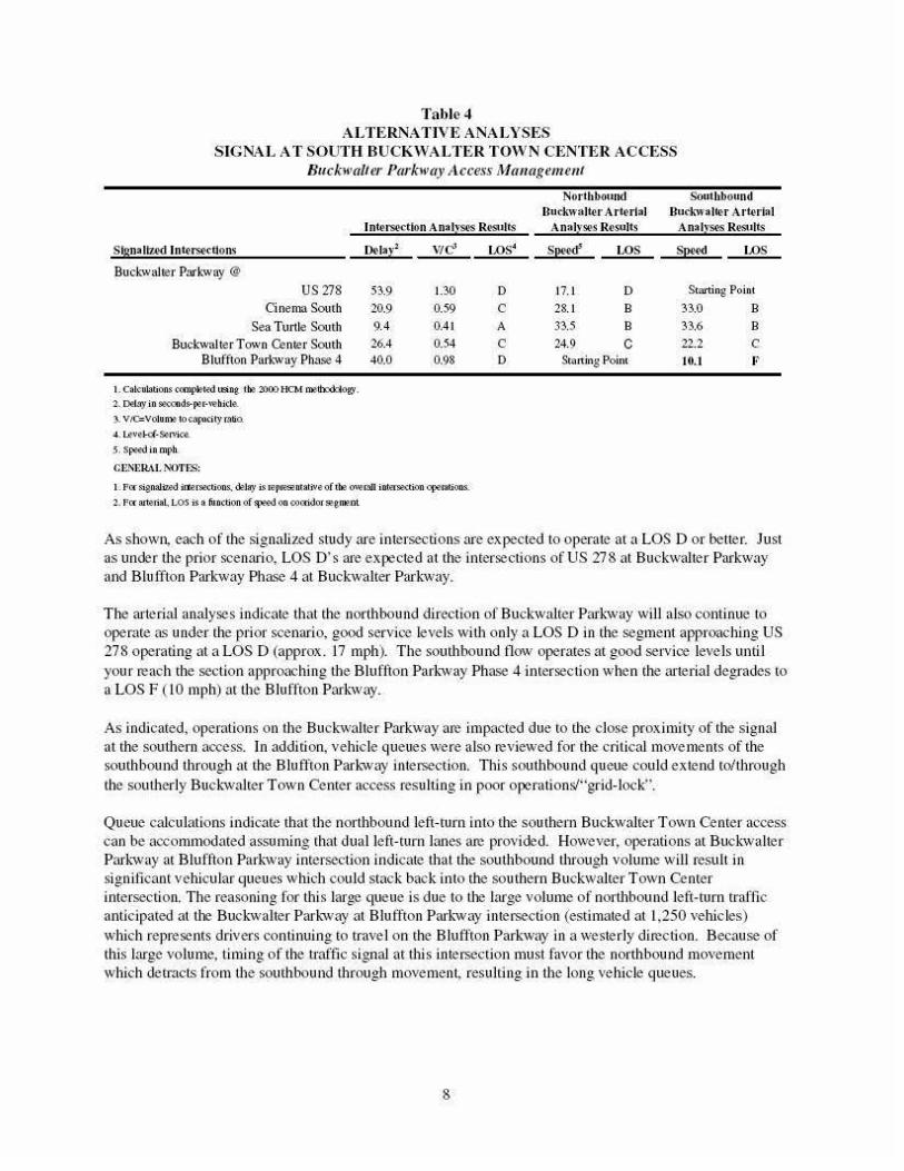
Table4 A LTERNATIVE ANALYSES
SIGNA L AT SOUTH BUCKWALTER TOWN CENTER ACCESS Buckw(l/ter Ptu·kw(l:y ;l ccess Managemmt
lnWrsedlon AnalvS(loS R~dts
Skmaltud lnt<'rs4!·dlons
Buck-walter Parkway @
US278 O nema South
Sea Turtle Som h Buckwalter Town Center Somh
Bluffton Parbvay Phase 4
1. Calcubtions ccmpk>-t"d U:!lifl@. ~~ 21:100 HCM l:ntll).~Oty.
2. 0111.'1)' in Sl'\.-onds-p.>r·whida
4. Levf"kl·So!rvica
s. Sj.Wd in mph.
CUNI~RAt 1\'0Tts:
De-lal·l wf!
53.9 1.30 20.9 0.59 9.4 0.41 26.4 0.54 40.0 0.98
1. P« SignaUz.i\1 ifteC'SIIX'f.ions.. dtJay is rep~ntaliveof the ~~mil iht~tion q:oemtions.
'2·. P« ~rial. LOS is a function of~ on ooCf'idorsae,roolll
LOS'
D c A
c D
Northb~•nd Southbound Buekwalter Arterial Bucl..-walil.'r At'(('rL.,I
Analyses Results Analv54!'S Rest•lts
sP"¢ LOS Sp«<t LOS
17. 1 D Starting Point 28. 1 B 33.0 B 33.5 B 33.6 B 24.9 c 22.2 c
Starting Point 10.1 F·
As shown, each of the signalized stud)' are intersections are expected to operate at a LOS D or better. Just as under the p1ior scenario, LOS o· s are expected at the intersections of US 278 at Buckwalter Parkway and Bluffton Parkway Phase 4 at Buckwalter Parkway.
The arterial analyses indicate that tbe northbound direction of Buckwalter Par~·way will also continue to operate as under the plior scenario, good service levels wi th only a LOS Din the segment approaching US 278 operating at a LOS D (approx. 17 mph). The southbound tlow operates at good service levels until your reach the sectjon approaching the Bluffton Parkway Phase 4 intersection when the arterial degrades to a LOS F ( 10 mph) at the Blulfton Parkway.
As indicated, operations on the Buckwalter Parkway are impacted due to the close proximjty of the signal at the southern access. In additjon, vehicle queues were also reviewed for the critical movements of the southbound through at the Bluffton Par~·way intersection. Thjs southbound queue could extend to/through the southerly Bucl.·walter Town Center access resulting in poor operation!'J·;grid-lock".
Queue calculations indicate that the northbound left-turn into the sou them Buckwalter Town Center access can be accommodated assuming that dual left-turn lanes are provided. However, operations at Buckwalter Par~·way at Bluflton Parkway intersection indicate that the southbound through volume will result in signiticaot vehjcular queues which could stack back into the southern Buckwalter Town Center intersection. The reasonjng for this large queue is due to the large volume of northbound left-turn traflic anticipated at the Buch valter Par~-way at Bluffton Parl.-way intersection (estimated at 1,250 vehicles) which represents drivers continuing to trave l on the BILtffton Parkway in a westerly direction. Because of thjs large \'Olume, timing of the traffic signal at this intersection must favor the northbound movement which detracts from the southbound through movement, resulting in the long vehicle queues.
8
DEVELOPMENT ACCESS/CONNECTIVITY
In order to maintai n traftic tlow on tile no1thern section of the Buckwalter Parkway, the location of signalized intersections must be properly planned and maintained. As such, not all acoess points will be allowed signalization at "front door'' locations along the frontage of tl1e site.
With tl1 is, the planning of good connectivit)' between developnJents is critical so that drivers can tra,•el fi·om one facilit)' to another without havi ng to get on the Buckwalter Parkwa)' and to allow access for traftic to one of the planned signalized intersections.
Connectivit)' is especially impo1tant for man)' of the paroe ls along the Bucl;walter Parl.'Wa)' due to development parce l size, environmental constraints/wetlands and proximity to major arterials such US 278 and the Bluffton Park'Wa)'. For parcels which front US 278, connectivit)' to the Buck'Walter Parkwa)' is cJitical as the approved acoess plan for US 278 limits full-access movement drives and signalized inte rsections.
In particular, tiu\!e developments have plans to access the Buckwalter Parhva)' identitied via t11eir approved tratlic studies and in some instanoes, their respective developnJent agreements. The Willow Run PUD, Island West and the proposed Buckwalter Commons retail site located along US 278 (opposite the Berke ley Hall maintenance acoess) are each plamJed to have access to/from the Buchvalter Parkwa)'.
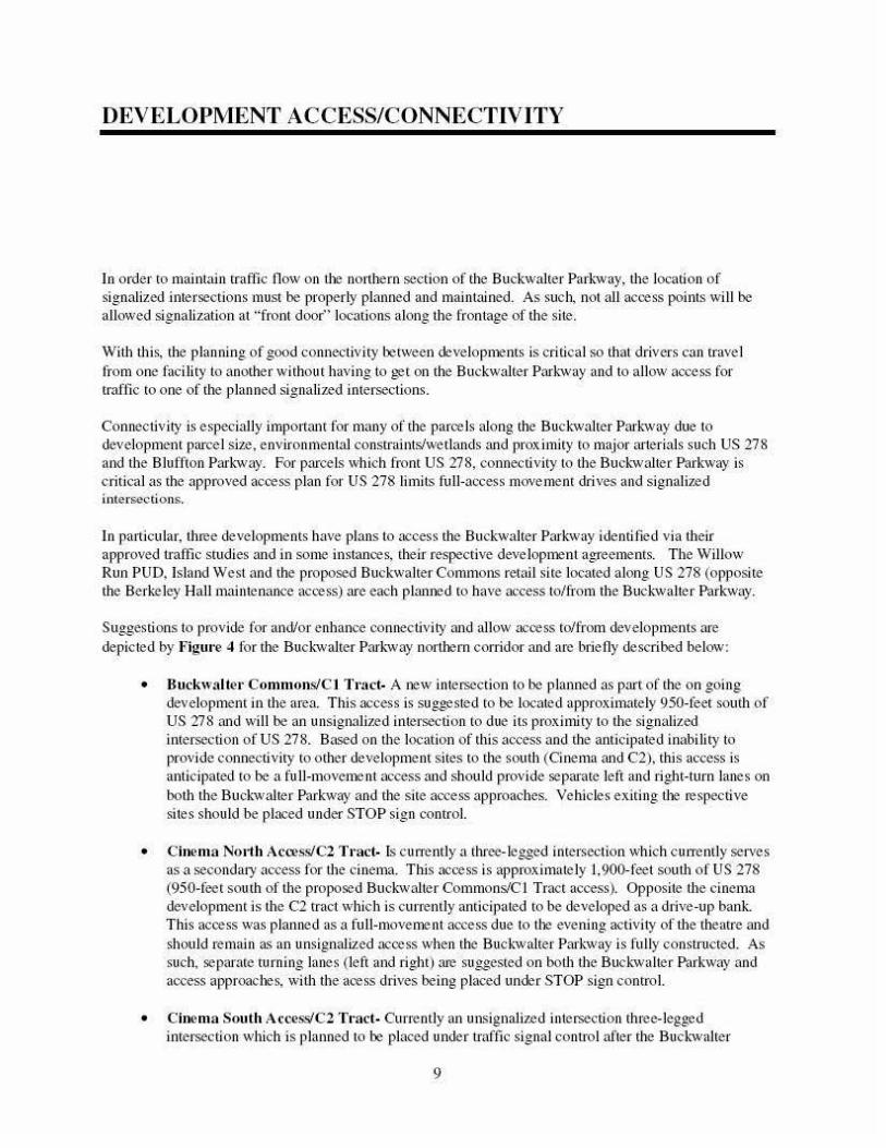
Suggestions to provide for and/or enhance connectivi ty and allow acoess to/from developments are depicted by Figm-e 4 for the Buch valter Parl.'Wa)' nortiJern corridor and are brieil)' described below:
• Buckwaltel' Commons/Cl Tl'acf:. A JJeW intersection to be planned as part of the on going development in the area. This access is suggested to be located approximate!)' 950-teet south of US 278 and wi ll be an unsignalized intersection to due its prox intity to the signalized intersection of US 278. Based on the location of this access and the anticipated inability to provide connectivity to other development sites to the south (Cinema and C2), this access is anticipated to be a fuJJ-movenJe nt access and should provide separate left and right-turn Janes on both the Buchvalter Parkwa)' and the site access approaches. Vehicles exiti ng tiJe respective si tes should be placed under STOP sign control.
• Cinema No11h Access!C2 Tl'act- Is cun·eml)• a three-legged intersection which cua·entJ)' serves as a secondary access for tl1e cinema. This acoess is approximately 1,900-feet soutl1 of US 278 (950-teet south of the proposed Buchvalter Commons!Cl Tract access). Opposite the cinema development is the C2 tract which is current))' anticipated to be developed as a drive-up bank. This acoess was planned as a full-movenJe nt access due to tiJe evening activity of the theatre and should remain as an unsignalized acoess when the Bucl'Walter Park'Wa)' is full)' constructed. As such, sepm·ate turning Janes (left and right) are suggested on both the Buckwalter Parkway and access approaclJes, wi dl the aoess dlives being placed under STOP sign control.
• Cinema South Access!C2 T1·act.- Current])' an unsignalized intersection three-legged intersection which is planned to be placed under n·affic signal conu·oJ after the Buch valter
9
Figure 4
BUCKWALTER PARKWAY ACCESS & CONNECTIVITY
Buckwalter Parkway Access Management: Bluffton, SC
•
Park-way is fully constructed. Alignment of the future C2 tract access once planned wi ll result in a four-Jegg)!d signalized imersection. Buck-walter Parkway approaches to this intersection should pro,•ide separate left and right-turn Janes on aU applicable approaches. Approaches for the Cinema and C2 tracts should pro,•ide a separate left-turn lane, a through Jane and a separate right-turn Jane. Access to/from the Willow Run PUD is suggested at this intersection by providing connectivity through adjacent property owners to the Willow Run project.
• Sea Turtle North Access!Pat·kside Drive- Currently an unsignalized full-movement access located approximately 1,000-feet south of the proposed signalized intersection at the Cinema south access. Access to remain as a full-movement unsignaJized intersection access with comp letion of the Buck·walter Parkway and the Sea Turtle development. On the west side of the Buck-walter Parkway, connectivity between the Sea Turtle development and tl1e cinema development is suggested in order to provide accessibilit)' to the proposed signal at the southerly cinema access.
It should be noted that this intersection was investigated in order to determine if signalization is current))' warranted at the existing access currently servi ng Wood Blidge sub-division. Based on counts conducted in March 2007 and historical counts conducted in November 2005, the site access wi ll not meet signalization requirements based on either the 4 or 8 hour warrant analyses. It should also be noted that whi le the peak-hoUJ signal warrant is margi nal))' met, installation of a signal based so lely on this warrant and not substantiated by eitller of tile greater warrants is not t)'pical.
• Sea Turtle South Access!CS & C6 Tt·acts- A planned future four-legged imersection which is suggested to be placed under n·affic signal control. Access to be located approximately 1,050-feet south of the Sea Turtle nonh access. If possible, extend the westerly leg of the intersection to the Woodbridge neighborhood in order to provide access for the neighborhood to a signalized intersection. Buckwalter Parkway approaches to this intersection should pro,•ide separate left and tight-turn latles on all applicab le approaches. Approaches fi·om the Sea Tunle and CS & 6 tracts should provide a separate left-ntrn Jane, a through Jane and a separate right-turn Jane. If connectivity to the Woodbridge neighborhood is not provided, the need for the separate eastbound and westbound through Janes on the minor street approaches will no longer be needed/required.
• Buckwalter Town Center- In total, tive access drives have been proposed for tl1is site one of which is planned to be placed u oder traftic signal control. The suggested location of this signalized location is discussed later in this repon. Connectivity of this de'•elopmem to planned development to tile west, the Sea Tunle development to the north and connectivity to the Island West development should be planned/provided.
Access talfrom this development should be planned by pro,•idi ng two full-movement access drives (one of which will be signalized) and spacing of the limited movenle nt (right-in/right-out) access drives at a minimum ofS00-600 feet from a full-movement access. Full-movement access dri,•es should provide separate turning Janes on all approaches (Buckwalter Park-way and access dri,•es) and align opposite access dtives serving the C6 tract located on the west side of the Buckwalter Parkway.
Depending on the tina) deve lopnlent proposal, which should include the entire Town Center project, the proposed access drives and separation should be refined which will likely reduce the number of access drives w the Buck-walter Park-way. It should be noted that the northbound leftturn movement e ntering the Buckwalter Town Center at the signalized access will likely require
10
dual left-turn lanes enteling tbe development due to the projected left-tllrn volumes. Limited movement access drives should provide separate light-turn deceleration lanes on the Buckwalter Park.'way.
As discussed later in this report, the separation of access drives to this tract and the future intersection of the Buckwalter and Blu ffton Parkways wi ll be important. Depending on which aligJlment of the Bluffton Parkway is se lected wi ll depend on the fu ture access to/li·om tJ1is site and the suggested location of the antici pated signalized access.
Jl
The installation of a temporary signal is permitted at Parker Drive which may be removed upon completion of
Phase 5B of the Bluffton Parkway, and the median opening at Parker Drive may be closed upon completion of
Phase 5B. Phase 5B alignment may remain as is, and as part of Phase 5B construction, two additional
residential access points may be simultaneously built to provide three residential access points for adjacent
residents.
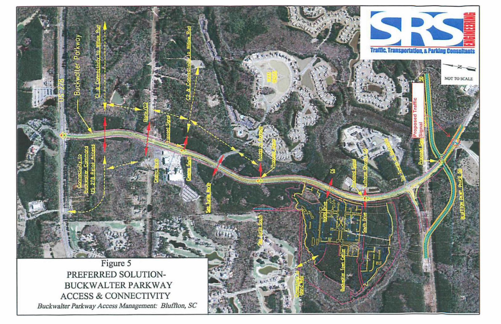
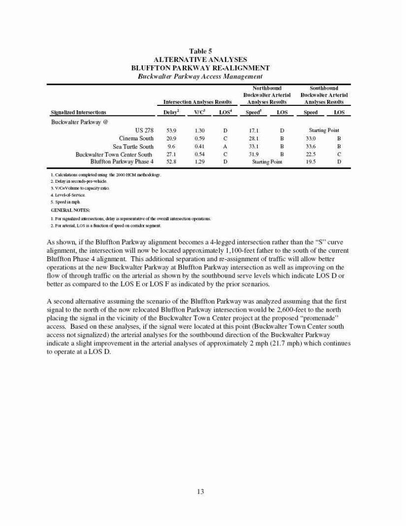
Table 5 ALTERNATIVE ANALYSES
BLUFFTON PARKWAY RE-ALIGNMENT Buckw(l/ter Ptu·kw(l:y ;l ccess Managemmt
Northb~•nd Southbound
lnWrsedlon AnalvS(loS R~dts
Skmaltud lnt<'rs4!·dlons
Buck-walter Parkway @
US278 O nema South
Sea Turtle Som h Buckwalter Town ~nter South
Bluffton Parbvay Phase 4
1. Calcubtions ccmpk>-t"d U:!lifl@. ~~ 21:100 HCM l:ntll).~Oty .
2. 0111.'1)' in Sl'\.-onds-p.>r·whida
4. Levf"kl·So!rvica
s. Sj.Wd in mph.
CUNI~RAt 1\'0Tts:
De-lal·l wf!
53.9 1.30
20.9 0.59
9.6 0.41
27.1 0.54 52.8 1.29
1. P« SignaUz.i\1 ifteC'SIIX'f.ions.. dtJay is rep~ntaliveof the ~~mil iht~tion q:oemtions.
'2·. P« ~rial. LOS is a function of~ on oonid..'YlieSI:OO:flL
LOS'
D c A
c D
Buekwalter Arterial Bucl..-walil.'r At'(('rL.,I Analyses Results Analv54!'S Rest•lts
sP"¢ LOS Sp«<t LOS
17.1 D Starting Point 28.1 B 33.0 B
33.1 B 33.6 B 31.9 B 22.5 c
Starting Point 19.5 D
As shown, if the Blu ffton Parhva)' alignment becomes a 4-legged intersection rather than the "S" curve alignmem, the intersection will now be located approx imately I, I 00-feet father to the soutl1 of the current Bluffton Phase 4 alignment. This additional sepru·ation and re-assignment of traffic wi ll allow better operations at the new Buckwalter Parkway at Bluffton Parkway intersection as well as improving on the tlow of through traffic on the ru·terial as shown by the southbound serve levels which indicate LOS D or betler as compared to the LOS E or LOS F as indicated by the prior scenarios.
A second alternative assuming the scenario of the Blu ffton Parkway was anai)'Zed assuming that the first signal to the north oftl1e now re located Bluffton Parkway intersection would be 2,600-feet to tl1e north placing the signal in the vicinity of the Buckwalter Town Center project at the proposed "promenade" access. Based on these analyses, if the signal were located at this point (Buckwalter Town Center south access not signalized) the ru·terial analyses for the southbound direction of the Buckwalter Parkwa)' indicate a slight improvement in the artelial analyses of approximately 2 mph (21.7 mph) wl1ich continues to operate at a LOS D.
13
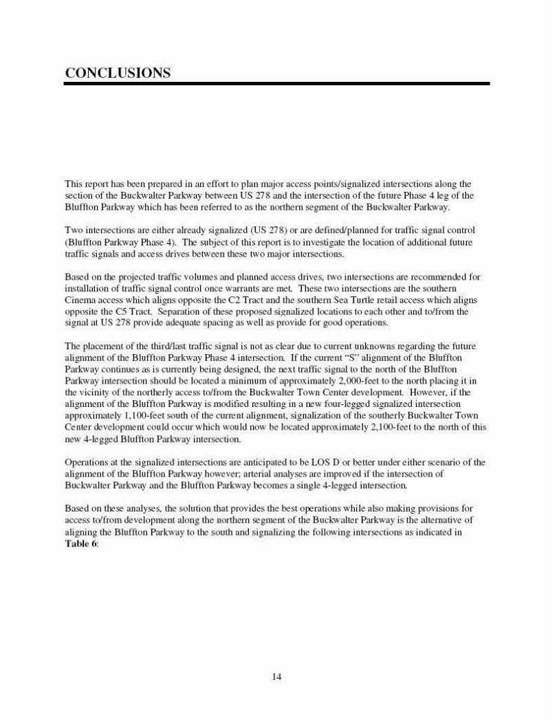
CONCLUSIONS
This report has been prepared in an effort to plan major access points/signalized intersections along the section of the Buckwalter Parkway between US 278 and the intersection of the future Phase 4 leg of the Bluftton Park-way which has been referred to as the northern segment of the Buckwalter Park-wa)'.
Two intersections are either alread)' signalized (US 278) or are defined/planned for traftic signal control (Biu fflon Parkway Phase 4). The subject of tltis report is to i1westigate the location of additional future traftic signals and access drives between these two major intersections.
Based on the projected traftic vo lumes and planned access drives, two intersections are recommended for installation of u·aftic signal conn·oJ once warrants are mel. These two intersections are llte somhern Cinema access which aligns opposi te the C2 Tract and the southern Sea Turtle retail access which aligns opposite the C5 Tract Separation of these proposed si_gnalized locations to each other and to/from the signal at US 278 provide adequate spacing as well as provide for good operations.
The placement of the third/last traffic signal is not as clear due to current unknowns regarding the future aUgnment of the Bluffton Parkway Phase 4 intersection. If the current "S" alignment of the Bluffton Parkwa)' continues as is cun·enti)' being designed, the next traftic signal to the north of the Bluffton Parkway intersection should be located a minimum of approx imate))' 2,000-feetto the north placing it in the ''icinity of the norliJeri)' access to/from the Buckwalter Town Center de\•e lopmenl. However, if iJJe aligJlment of the Bluffton Parkway is modified resulting in a JlCW four-legged signalized intersection approximately I , I 00-feet south of the curre nt alignment, signalization of tlte southerly Buckwalter Town Center development could occur which wou Jd now be located approximately 2,1 00-feet to tile north of this new 4-Jegged Bluffton Park·way intersection.
Operations at tiJe signalized intersections are anticipated to be LOS D or better under e ither scenruio of the aligJtment of the Bluffton Parkway however; arterial analyses are improved if the intersection of Buck-waller Park·way and the Bluffton Parkway becomes a single 4-legged intersection.
Based on tiJese analyses, the solution that provides the best operations while also making provisions for access to/from development along the northern segment of tlte Buck-waller Parkway is the alternative of aligJting the Bluffton Parkwa)' to the south and signalizing the following intersections as indicated in Table 6:
14
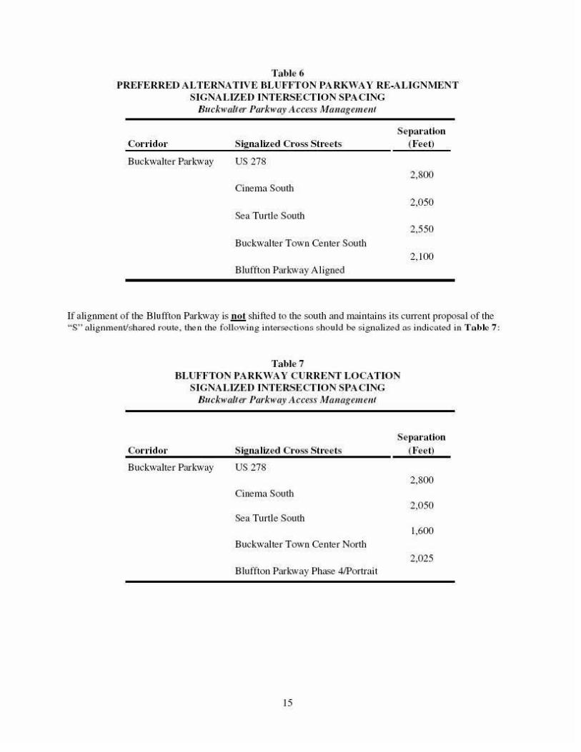
Ta ble 6 PREFERRED ALTERNA TJVE BLUFFTON PARKWAY RE -ALIGNMENT
SIGNALIZED INT ERSECTION SPACING Buckwalter Parkway Access Mtuwgem.ellt
Col'l'idor Signa lized Cross Sh ·eels Se1>a1·ation
(Feet)
Buckwalter Parkway US278 2,800
Cinema Sou d1 2,050
Sea Turtle South 2,550
Buckwalter Town Center Soutl1 2, 100
Bluffton Parkway Aligned
If alignment of the Blu ffton Parhva)' is .!!.2! shilted to the south and maintains its ClLrrent proposal of the ;•s·~ :..Jignmentlshnred route. the n the fo llo wing interooc t-ioos sho uld be s ig na lized :ts indicated in T o bie 7 :
Col'l'ido•·
Ta ble? BLUFFTON PARKWAY CURRENT LOCATION
SIGNA LIZED INTERSECTION SPACING BucJ.,,,,,dter i'llrkwlly Access Mauageme/11
Signa lized C1·oss S tL·eets
Sepa1·ation (Feet)
Buckwalter Pari-way US278 2,800
Cinema South 2,0 50
Sea Tltrtle South 1,600
Buckwalter Town Center North 2,025
Bluffton Pm·kway Phase 4/Portrait
15
APPENDIX
• Capacity & Arterial Analyses
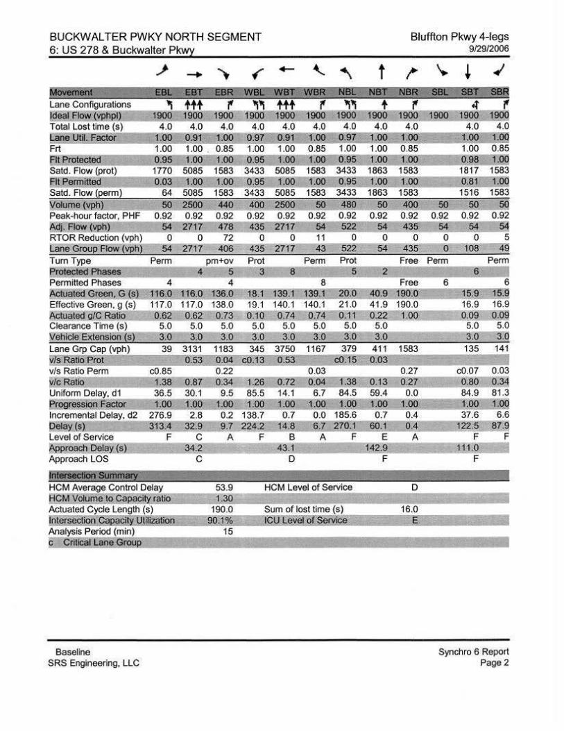
BUCKWALTER PWKY NORTH SEGMENT 6: US 278 & Buckwalter Pkwy
~ - ..... • - "-.. ~ M6Y'iiiriiill EB~ EBI' Lane Conftgurations 'I ttt !cl'~l FIQw ~) 11!!19.: 1900 Total Lost lime (s) 4.0 4.0
n il 0. 1.00 Frt 1.00 . 0.85 1.00 Cl1Ero!QC!i!J !&Q !.Qg;::~§ Satd. Flow (prot) 5085 1583 3433 5085
E!1.Eewrtt~ g,o~ l:OO j.oo g:ss- l.QQ Satd. Flow (eerm) 64 5085 1583 3433 5085
Wolume !YP.!Jl 50 sqg 440 ..iQ!l_ 2500 Peak-hour factor, PHF 0.92 0.92 0.92 0 .92 0.92 Adj.~(~ 2717 478 ~~5 2717 RTOR Reduction (vph) 0 0 72 0 0 Lane GrOUp Flow (vp~54 2717 406 435 2717 Tum Type Perm pm+ov Prot Perm Prot E..rotecte<i Phases 4 5 3 8 5 Permitted Phases 4 8 ~ate<!Green. G (sj 116.0 136.0 139.1 20.0 Effective Green, g (s) 138.0 140.1 21.0 Actuated g/C Rat10 0.73 0.74 0.11 Clearance-Time (s) 5.0 5.0 5 .0 ~ehiCle Extens•on (s) 3.0 3.0 3.0 Lane Grp Cap (vph) 39 3131 1183 345 1167 379
l!ls.,Batio !;:t2! Q~53 Q.Q:l ~.l~ g,~ {lg, 15 v/s Ratio Perm c0.85 0.22 0.03 WS'Ratici 0.34 J26 o.z2 g.g~ l~ Uniform Delay, d1 9.5 85.5 14.1 6.7 84.5 f!rogresslon !'actor 1.00 ~.00-=1,00::1 .00-J Q!l Incremental Delay, d2 0.2 138.7 0.7 0.0 185.6 Q~a~ s 9.7 224.2 1<1.8 6,Z ~ZO,J Level of Service A F B A F ~roach Delay (s) 43.1 Approach LOS D
!iliili'iiCildfl'M11!81Y HCM Average Control Delay 53.9 HCM Level of Service
B~M.Yilume~tQCa~.rnli2 J3Q Actuated Cycle Length (s) 190.0 Sum of lost time (s) IOle[S61:1iOILCapec'~U!liizatiog 90J % I~C: ~evei :Qt ~~D:9 Analysis Period (min) 15
C'!' I e
Baseline SRS Engineering, LLC
t
50
2
40.9 41.9 022
5.0 3.0 411
0
Ql~ 59.4
J:oo 0.7
60.J E
J~.9 F
Bluffton Pkwy 4-legs 9/29/2006
~ ..,.
+ ..' NBK¥SS81: SBI ~ ssR ., 1900
4.0 1.00 0.85 1.00
1583 1.0Q
1583 400 0.92 435
0 435
Free
1583
0.27 Q.2Z 0.0
J QQ 0.4 0,1;
A
c D
16.0
&
<t ., 1900 1900 1900
4.0 4.0 1.00 t:oo 1.00 0.85 O.!lll= 1 ,o~ 1817 1583 0.81 r,oq 1516 1583
50 sq 0.92 0.92 0.92
54 54 0 0 5 0 108 49
Perm Perm 6
6 6 15.9 15.9 16.9 16.9 0.09 0.09
5.0 5.0 3.0 3.0 135 141
c0.07 0.03 0,80 0.~ 84.9 81.3
l:!lll j ,QQ 37.6 6.6
)22,5 ~7.~ F F 0 F
I
I
Synchro 6 Report Page 2
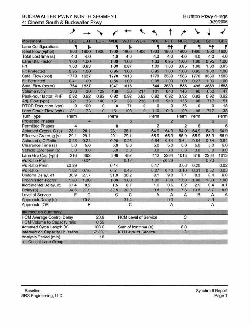
BUCKWALTER PWKY NORTH SEGMENT 4: Cinema South & Buckwalter Pk~
__,. - .. • - ' ~ t ~oYiirieilt EBt:: EBT EBR--wet: WBR- NBC
"' "' l]"oo 1 ~00 4.0 4.0
1 100 Frt 1.00 1.00 E!ie@e~ g ;9s 0.95 Said. Flow (prot) 1770 1770 3539 E!l~rmitt~ UJj l:qg 0.:!§- l.QQ Satd. Flow j~erm) 764 1637 644 3539 to£olume (vl!h) 203 ~ 1~ 7 101 840 Peak-hour factor, PHF 0.92 0.92 0.92 0 .92 0 .92 0 .92 Ml- Flow vji!l :.2,61 33 140 2~ 110 3 RTOR Reduction (vph) 0 100 0 0 0 0 Lane Grou~ Flow (vptl) 221 73 0 110 913 Tum Type Perm Perm Perm Protected Phases 4 8 2 Permitted Phases 4 8 !\cluatedGreen, G (s) 28.1 28.1 28.1 28.1 Effective Green, g (s) 29.1 29.1 29.1 29.1 ~tualed g/C Ratio 0.28 0.28 0.28 0.28 Clearance Time ( s) 5.0 5.0 5.0 5.0 llfehicle Extens1on js) 3.0 3.0 3.0 3.0 lane Grp Cap (vph) 216 462 296 457 412 ~ffiatiS Prot g,g! QJ~ v/s Ratio Perm c0.29 0.14 0.17
1!/.lt. Ratio l 0' OJ 6 O.§J 0,~3 Q~Z !lJQ Uniform Delay, d1 36.9 27.7 31.0 30.2 8.1 9.0 f:[Qgression FJ!.I<!ot J.OO J.OO 1.00 !-00 J,OO J,OO Incremental Delay, d2 67.4 0.2 1.5 0.7 1.6 0.5 Deta:.:: (s! JO,p 2Z:.9 32.5_ 30.9 9.§ 9,5 Level of Service F c c c A A ~ppcoact:u:;>elay s 0.8 31 9.3 Approach LOS E c A
Jiitii iiCiiiii I §UIIIfii8IY HCM Average Control Delay ffC~l!,!!Jl§ t~a~ly~ Actuated Cycle Length (s) IOtersectOO CaoB ty UtiJiijtion §Z~§~
Sum of lost time (s) I~Y bevel~;~~~
Analysis Period (min) 15
li "dt&i billl!il g~
Baseline SRS Engineering, LLC
Bluffton Pkwy 4-legs
~
l·!!.!! 1583
Perm
2 64.9 65.9 0.64
5.0 3.0
1013
0 .06
QJQ 7.1
J.m 0.2
z~ A
8.0
9/29/2006
'. ~ ~
B(4 SBf 'SBR tt .,
1900 1~ 4.0 4.0 .95 .Od
1.00 1.00 0.85 ~;95 1;oo j,OQ 1770 3539 1583 0~ l,OO. 498 1583 90
0.92 98 0
98 Perm Perm
6 6 64.!1 64.9 64.9 65.9 65.9 65.9 0.64 0.64 0.64 5.0 5.0 5.0 3.0 3.0 3.1'l
319 2264 1013 g.~ ]
0.20 0.02 !t 3J Q-~~ Q,O~
8.3 8.4 6.8 J,OO J ~QQ JQg 2.5 0.4 0.1
J0.6 §Z §.~ B A A
9 A
Synchro 6 Report Page 1
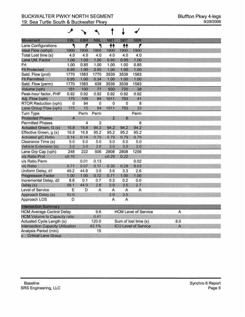
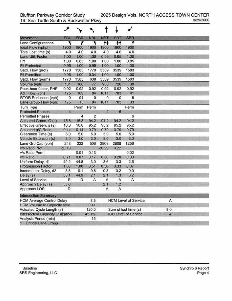
BUCKWALTER PWKY NORTH SEGMENT 19: Sea Turtle South & Buckwalter Pkwy
6:95 1770 0.95 1770 1583
161 100 0.92 0.92 175 109
0 94 175 15
Perm 4
248 222 cO.JO
0.01 0.71 0.07 49.2 44.8
1.00 0.1
44.9 D
Baseline SRS Engineering. LLC
1770 0.34 638 77
0.92 84 0
84 Perm Perm
2 6
506 2808 2808 1256 C0.29 0 22
0.13 0 .02 0. 17 0.36 0.03
3.0 3.6 2.6 0.72 O.Z.1
0.7 0.3 2.r-2.9
A
9.6 0.41
120.0 43.1%
15
A 2.9
A
Sum of lost time (s:t.) __ ICU level of Sprv1ce
Bluffton Pkwy 4-legs 9/29/2006
8.0 A
Synchro 6 Report Page 5
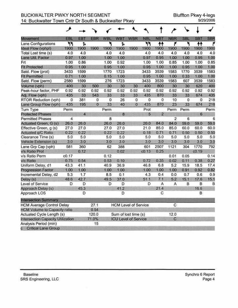
BUCKWALTER PWKY NORTH SEGMENT Bluffton Pkwy 4-legs 14: Buckwalter Town Cntr Dr South & Buckwalter Pkwy
~ - .. ~ - ' ~ t ~ J,fO\WII8nt EBC"" E8T E8R WBL W8f"'!'WBR NB( NBT Lane Configurations 'I 'I f- 'I f- '1'1 tt '(' ldeaf F. (Y!WP 1900 1900 900 190o-T900 1000:=1~ Total Lost time (s) 4.0 4.0 4.0 4.0 4.0 4.0 4.0 Lane Utll. Factor o:91 1.00 1.00 1.00 0.97 1.00 Frt 1.00 0.86 1.00 0.92 1.00 1.00 0.85 Flt Protected 0.95 1.00 0.95 1.00 0.9 1.00 1.00 Satd. Flow (prot) 3433 1599 1770 1723 3433 3539 1583 'FifPenmtted 0.71 1.00 0.1 1.00 0.95 1.00 1.00 Satd. Flow (eerm l 2580 1599 276 1723 3433 3539 1583 :Volume YP,l)) 30 500 30 30 soo_ 30 Peak-hour factor, PHF 0.92 0.92 0.92 0.92 0.92 0.92 Mj. Flow (VRb) 33 543 33 33 -szo 33 RTOR Reduction (vph) 381 0 0 26 0 10 Lane Group Flow (vph 195 0 33 40 870 23 Tum Type Perm Perm Prot Perm
rotected ses 4 8 .5 ~ Permitted Phases 4 8 2 1\CIUated"Greeo. G.:ID:: 26.0 26.0 26.0 26.0 20. 840 84.0 Effective Green, g (s) 27.0 27.0 27.0 27.0 21.0 85.0 85.0 ~tua ed g/C Rallo 0.22 0.22 0.22 0.22 0.18= 0.71 - 0.71 Clearance Time (s) 5.0 5.0 5.0 5.0 5.0 5.0 5.0 :Vehicle Extension (s) 3.0 3.0 3.0 3.0 3.0 3.0 3.0 Lane Grp Cap (vph) 581 360 62 388 601 2507 1121 /s Ratio Prot 0.12 0.02 C0.13 0.25
v/s Ratio Perm c0.17 0.12 0.01 v/c Ratio 0.75 0.54 0.53 0.10 0.72 0.35 0.02 Uniform Delay, d1 43.3 41 .1 40.9 36.9 46.8 6.8 5 .2 pr~lQii Factor 1.00 1.00 1.00 1.0 1.00 1.00 1.00 _Incremental Delay, d2 5.3 1.7 8.5 0.1 4.3 0.4 0.0 Qel y~) ~-6 42.7 49.5 37 0 51 .1 7.1 5.2 Level of Service D D D D D A A NJe!Pach Delay ( s) 45.3 4~ 21.4 Approach LOS D D c )nlil'iiiiitiiSiiiillri!iij HCM Average Control Delay HCM Volume to Ca~ci~ ratio Actuated Cycle Leng1h (s) Sum of lost time ( s) 12.0 Intersection Ca~ Utilization ICU Level of Service c Analysis Period (min) c Critical lane GrouP.
Baseline SRS Engineering, LLC
9/29/2006
'-. ~ ~
SBR tt '('
l900 mrj@ 4.0 4.0
0.95 roo 1.00 0.85 1.00 1.00
1770 3539 1583 0.33 1.00 1.00 607 3539 1583 30 620 ~
0.92 0.92 0 .92 33 674 435 0 0 218
33 674 218 Perm Perm
6 6 59.0 59.!!; §2-.il 60.0 60.0 60.0 0.50 0.50 O.sd 5.0 5.0 5.0 3.0 3.0 30 . '
304 1770 792 C0.19
" 1
Synchro 6 Report Page4
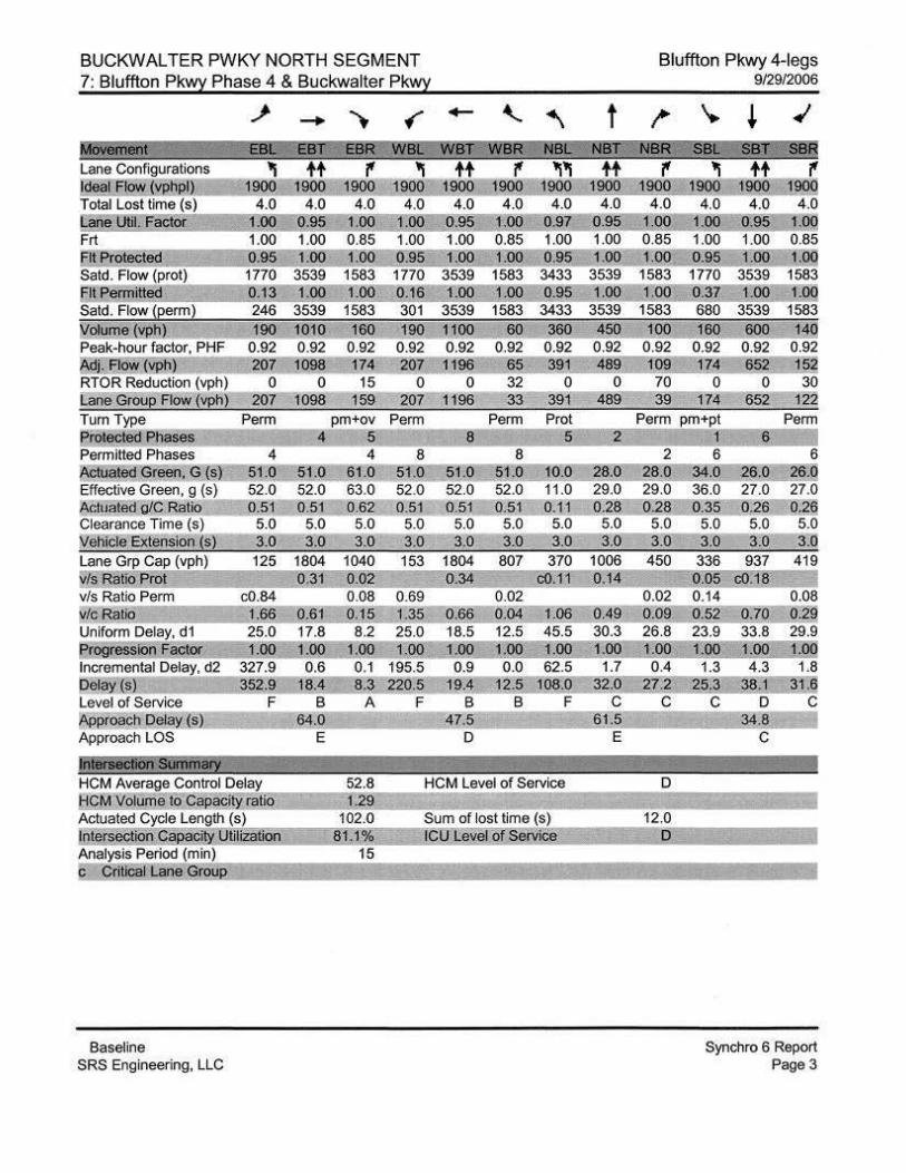
BUCKWALTER PWKY NORTH SEGMENT Bluffton Pkwy 4-legs 7: Bluffton Pkw~ Phase 4 & Buckwalter Pk~ 9/29/2006
.J' - .. {" - ' ~ t ~ '. ~ ~ '-EBI-I!l!!""EiiT ESR WEll: Wlif -WBR liiBI: NBf '§if,' S8!!
'I tt '(' 'I tt '(' 'I 'I tt 'I tt '(' 1900 1900 1900 1900 1900 19oo:J90Q l900 ll!QQ 19o9...:.t!160 m
4.0 4.0 4.0 4.0 4.0 4.0 4.0 4.0 4.0 4.0 4.0 4.0 1.00 0.95 1.00 1.00 0.95 1.00 0.97 0. 5 00 .00 0.95 .00 1.00 1.00 0.85 1.00 1.00 0.85 1.00 1.00 0.85 1.00 1.00 0.85 0.95 1.00 1.00 0.% 1.00 1.00 0.95 1.00 1.00 0.95 1.00 1.og 1770 3539 1583 1770 3539 1583 3433 3539 1583 1770 3539 1583 0-:13 1.00 1.00 0.16 1.00 1.00 0.95 1.00 1.00 0.37 - 1.00- 1.00 246 3539 1583 301 3539 1583 3433 3539 1583 680 3539 1583
190 1010 160 60 360 ~50 JOO d 0.92 0.92 0.92 0.92 0.92 0.92 0.92 0.92 207 1098 174 65 391 ss~ J09 l~ J~
0 0 15 32 0 0 70 0 30 207 1098 159 33 391 489 39 174 1~
Perm Perm Perm Prot Perm
Permitted Phases 4 8 2 6 f,ctuated Greeo, G (s) 5 0 61.0 5LO JO.O 28.0= 2a.g 2t4.g ~6.0 26.g Effective Green, g (s) 52.0 63.0 52.0 52.0 11.0 29.0 29.0 36.0 27.0 27.0 lll.ctuated g/C Ratio 0.51 0.62 O§J... 0.51 0.1C 0.28 0.28 Q.3!l 0.26 Q.2q Clearance n me (s) 5.0 5.0 Vehicle Extension (s) 3.0 3.0 Lane Grp Cap (vph) 1804 1040 ~~ Rat10 Prot 0.31 0.02 v/s Ratio Perm c0.84 0.08 v/c Ratio 1.66 0.61 0.15 Uniform Delay, d1 25.0 17.8 8.2 flQ9@§slqn F aet()( 1.00 .00 1.00 Incremental Delay, d2 327.9 0.6 0.1 Delay~) 352.9 18.4 !!.3 Level of Service F B A ~proach Delay (s) 64.0 Approach LOS E
,li\IBI'S8Cil0n Slilifu8i'i HCM Average Control Delay 52.8 HCM Volume to Capaci!Y ratio 1.29 Actuated Cycle Length (s) 102.0 , ntersection Capac[ty UutiZaUon 81.1% Analysis Period (min) 15 c Critical lane GrouP.
Baseline SRS Engineering, LLC
5.0 5.0 5.0 3.0 3.0 3.0
153 1804 807 370 0.34 c0.1
0.69 0.02 1.35 0.66 0.04 1.06 25.0 18.5 12.5 45.5 1.00 1.00 1.00 1.00
195.5 0.9 0.0 62.5 220.5 19.4 12.5- 108.0
F B B F 47.5
D
HCM Level of Service
Sum of lost time (S) ICU Level of Service
5.0 5.0 3.0 3.0
1006 450 0.14
0.49 30.3 1.00 1.7
32.0 c
61.5 E
D
12.0 0
5.0 5.0 5.0 3.0 3.0 3.0
336 937 419 0.05 c0.18 0.14 0.08 0.52 0.70 0.29 23.9 33.8 29.9 1.00 1.00 1.00 1.3 4.3 1.8
25.~38.1 31.6 c D c
34.8 c
1
Synchro 6 Report Page3
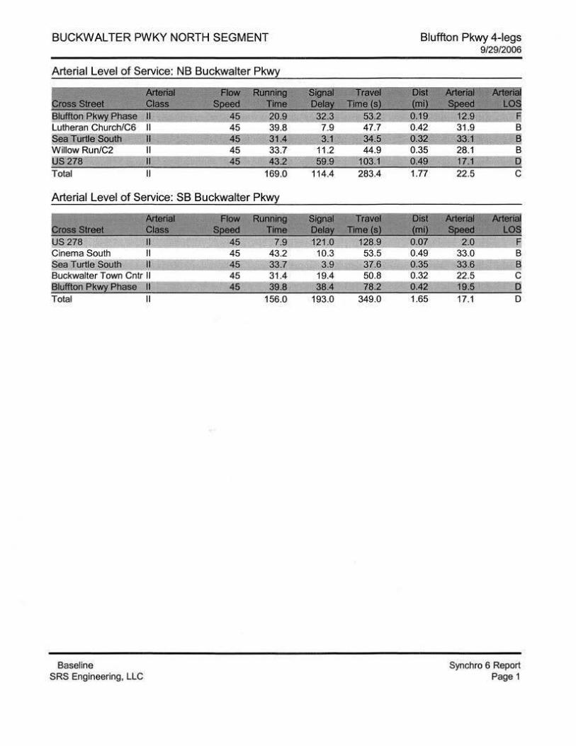
BUCKWALTER PWKY NORTH SEGMENT
Arterial Level of Service: NB Buckwalter Pkwy
~S1reet Ariiirii FloW Rllr1oiniJ Class SDeed rme
Bluffton Pkwy Phase 45 20.9 Lutheran Church/C6 45 39.8 Sea TurUe South 45 31,4 WillowRun/C2 45 33.7 US278 45 43.2 Total 169.0
Arterial Level of Service: SB Buckwalter Pkwy
~rosa Street Aitiiriiil FloW RUilllii(j Class Speed Time
US278 45 7.9 Cinema South 45 43.2 Sea Turtle South 45 33.7 Buckwalter Town Cntr 45 31.4 Bluffton Pk~ Phase 45 39.8 Total 156.0
Baseline SRS Engineering, LLC
~ ,:,~ 32.3 53.2 7.9 47.7 31 34.5
11.2 44.9 59.9 103.1
114.4 283.4
= 121 .0 10.3 3.9
19.4 38.4
193.0 349.0
Bluffton Pkwy 4-legs
1.77
0.07 0.49 0.35 0.32 0.42 1.65
9/2912006
12.9 !;
31.9 B 33.1 B 28.1 B 17.1 0 22.5 c
~ 2.0 5
33.0 B 33.6 B 22.5 c 19.5 D 17.1 0
Synchro 6 Report Page 1
BUCKWALTER PWKY NORTH SEGMENT
II II
S278 II Total II
Arterial Level of Service: SB Buckwalter Pkwy
!JS278 Cinema South II
se!! Il!i:!!,g Soull:i ,, ~5 33 4 Buckwalter Town Cntr II 45 25.1 ~Uffton PJ<~ Phase II 45 43.3 Total II 153.2
Baseline SRS Engineering, LLC
103. 280.8
Bluffton Pkwy 4-legs 10/9/2006
§ D D D
Synchro 6 Report Page 1
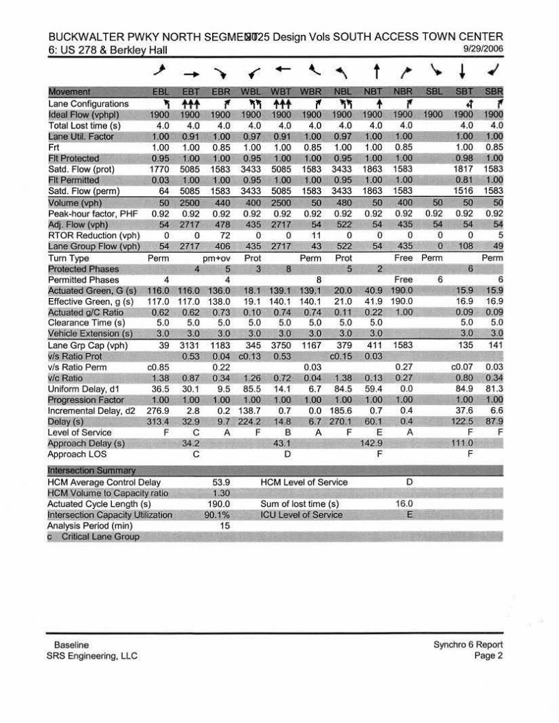
BUCKWALTER PWKY NORTH SEGME~IJ25 Design Vols SOUTH ACCESS TOWN CENTER 6: US 278 & Berkle:L Hall
~ - .,. MOViii'terit I ;
Lane Configurations klealFB vl:!!'_p!) Total Lost time (s) &_ane Util. Factor Frt Fit Protect Said. Flow (prot)
II Penmitted Satd. Flow (penm)
Vplurne. iYP1ll 50 gsoo ~0 Peak-hour factor, PHF 0.92 0.92 0 .92 ~i.£10\:'t (Ypb) ~ ~ZJZ ~Z.!! RTOR Reduction (vph) 0 0 72 Lane Grou!! Flow (Vph) 54 2717 406 Turn Type Perm pm+ov Et.2!2cti3ll. Pli 5 Permitted Phases 4 4 fA!! te G n G s) 16.0 116.0 36.0 Effective Green, g (s) 117.0 117.0 138.0 :AC!uatei:l g/C atio .62 0.62 Q.Z3 Clearance Time ( s) 5.0 5.0 5.0 lv'ehide Extension (s) 3.0 3.0 3.0 Lane Gp Cap (vph) J s Ratio Prot
39
v/s Ratio Penm c0.85 Y/c Ratio 1.38 0.87 Uniform Delay, d 1 36.5 30.1 e...rogression Factor 1.00 1.00 Incremental Delay, d2 276.9 2.8 bela~ (s) 313.4- 32.9 Level of Service F c A ~proach Delay (s) 34.2 Approach LOS c )i'iliriiiiCtlii Siii'iimiiJY ; ~
' HCM Average Control Delay 53.9
olume o Capacity ratio 130 Actuated Cycle Length (s) 190.0 liitersecllog,Capaci!Y .JJtillZation 90.1% Analysis Period (min) 15 c_,Critical ne Group
Baseline SRS Engineering, LLC
• - ' ~ t NBC
~og ii:500 !1Q ~!I ~ 0.92 0.92 0.92 0.92 0.92 ~35 ~ZJZ 54 52~ 54
0 0 11 0 0 435 2717 43 522 54
Penm Prot 5 2
8 8 1 9 1 391 20.0 40.9
19.1 140.1 140.1 21 .0 41.9 0.10 1!,74 0.74 Q. 1J 0.22 5.0 5.0 5.0 5.0 5.0 3.0 3.0 3.0 3.0 3.0
1167 411 0.03
0.03 0.72 0.04 1.38 14.1 6.7 84.5 100 1.00 1.00
0.7 0.0 185.6 14.8 6.7 270.1
B A F 43.1
D
HCM Level of Service
Sum of lost time (s) 1 u .Le:tel ,o .serx~
9/29/2006
~ \. ~ ~
NB!t 'Sst '.iSBl:- SBR f
12QO 4.0 00
0.85 to<! 1583 J:gO 1583
iQO 0.92 435
0 435
Free
Free 190.0 190.0 1.00
1583
0.27 o.2z 0.0
O,i A
D
16.0 E
4' f 9.2!,! 1~ 19®
4.0 4.0 1.00 .00 1.00 0.85 a.s~--LQ!! 1817 1583 ~]] :H2 1516 1583
~50 ~ 0.92 0.92 0 .92
54 54 ~ 0 0 5 0 108 49
Perm Perm 6
6 6 15.9 15.9 16.9 16.9 0.09 0.00
5.0 5.0 3.0 3.0 135 141
c0.07 0.03 Q.80 o.~ 84.9 81 .3 J,OO JOQ 37.6 6.6
l~~.s 8Z.9. F F
~lJ.O I F
I
Synchro 6 Report Page 2
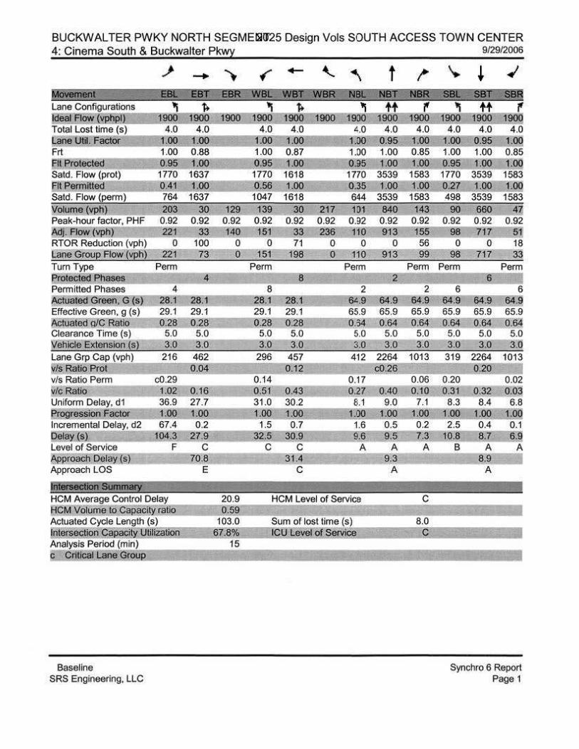
BUCKWALTER PWKY NORTH SEGMEISI025 Design Vols SOUTH ACCESS TOWN CENTER 4: Cinema South & Buckwalter Pk~
~ - .. .. ~ :z; EBIFWBL lane Configurations 'I f> 'I
eal Flow 'PJ1e!l 1900 1900 1900 1900 Total lost time (s) 4.0 4.0 4.0 Gille Uilt Factor .00 1.00 1.00 Frt 1.00 0.88 1.00 FH Prot 0.95 .oo 0.95 Said. Flow (prot) 1770 1637 1770 ~I! Permitt!Z! 0.41 1.00 0.56 Said. Flow (perm) 764 1637 1047 Wolume(y~ 203 30 129 139 Peak-hour factor, PHF 0.92 0.92 0.92 0.92 ~.Flow ( h 221 33 140 151 RTOR Reduction (vph) 0 100 0 0 lane Groue Flow (~h) 221 73 0 151 Turn Type Perm Perm Protected Phases 4 Permitted Phases 4 8 ~tuated Green G (s) 28.1 28.1 28.1 Effective Green, g (s) 29.1 29.1 29.1 11\Ctuated g/C Batio 0.28 0.28 0.28 Clearance Time (s) 5.0 5.0 5.0 Wehide Extension (s) 3.0 3.0 3.0 Lane Grp Cap (vph) 216 462 296 Is Ratio Prot 0.04
v/s Ratio Perm c0.29 wlc Ra ·o 1.02 0.16 Uniform Delay, d1 36.9 27.7
l!@;lr§!l§Jeii!A911lt 1.00 1.QO Incremental Delay, d2 67.4 0.2
~iill 104.3 27.9 Level of Service F c ~pwoiiCh:Delay ® 70.8 Approach LOS E
fr.t&iiidlOri Siiiimary HCM Average Control Delay HCM Volum!jl to Capaci ratio Actuated Cycle length (s) Intersection Ca~ tilization Analysis Period (min)
!< Critical rane Grou
Baseline SRS Engineering, LLC
9/29/2006 - ' ~ t ,.. '. ~ ~ WB IC"2Wtik i Nj; >:; NtsfZ' Mik«tJ@ WI' 'i58ft
f> 1900 1900
4.0 1.00 0.87 1.()() 1618 1.00
1618 30 217
0.92 0.92 33 236 71 0
198 0
8
28.1 29.1 0.28
5.0 3.0
457 0.1~
0.43 30.2 100
0.7 ;JQ, 9
'I t t f' 'I tt f' 19tl<!- 1900 1900 1900 - 1900 1900
4.0 4.0 4.0 4.0 4.0 4.0 100 0.§5 r.oo 0.95 1.6q 1.00 1.00 0.85 1.00 1.00 0.85 0.~5 1.i50 1.~.95 1.00 1.00 1770 3539 1583 0.35 1.oo--roo 644 3539 1583 101 840 143
0.92 0.92 0.92 110 913 155
0 0 56 110 913 99
Perm Perm 2
412 2264 1013 C0.26
0.17 0.06 0.27 ..2,40 0.10
8.1 9.0 7.1 1.00 1.QO
1.6 0.5 0.2 9,§,: :11·5 7.3
A A A 9.3
A
8.0 c
1770 3539 1583 0.27 1.00 .00 498 3539 1583 90 660 4B
0.92 0.92 0.92 98 717 51
0 0 18 98 717 33
Perm Perm 6
6 64.9 64.9 65.9 65.9 0.64 0.6 5.0 5.0 3.0 3.0
319 2264 1013
~ 0.20 0.02 0.31 0.32 0.03, 8.3 8.4 6.8
J.OQ l !QQ l ,O.Q 2.5 0.4 0.1
10,8 a,z 6,2 B A A
8.9 A
I
Synchro 6 Report Page 1
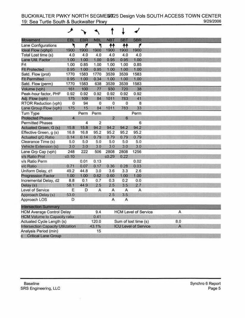
BUCKWALTER PWKY NORTH SEGMEilliJ25 Design Vols SOUTH ACCESS TOWN CENTER 19: Sea Turtle South & Buckwalter Pkwy 9/29/2006
It r ij(j Satd. Flow (prot)
II itt Satd. Flow !~rm) Wolume (vph) 161 100 Peak-hour factor, PHF 0.92 0.92 ~Aow(vph) 175 109 RTOR Reduction (vph) 0 94 Lane Group Flow (vph) 175 15 Tum Type Perm ProtectEi<rPhases 4 Permitted Phases 4 11\d\Jated Green, G (s 15.8 Effective Green, g (s) 16.8 1\ctuated g/C Ratio 0.14 Clearance Time (s) 5.0 W9hide Extension {s! 3.0 Lane Grp Cap (vph) 248 222 v/~.Ratio Efgl j;;Q.J,!j vis Ratio Perm 0.01 ~f!i;,Batig g.zj o.oz Uniform Delay, d1 49.2 44.8 f@jressio!l.factor J;gg l~m Incremental Delay, d2 8.8 0.1 Ret~M ~;l ti·~ Level of Service E D ~J>roach Delay.J s 3. Approach LOS D
Jnflneellon summary HCM Average Control Delay RCM YJ.)IUfi!!UO Capacity ratio Actuated Cycle Length (s} [nJ!!®ction Ca~ Utili;;a,tion Analysis Period (min)
!i ktili~ ~ane Group
Baseline SRS Engineering, LLC
77 0.92
84 0
84 Perm
2 94.2 95.2 0.79 5.0 3.0
506
0 .13
OJZ. 3.0 0.6~ 0.7 2:5
A
t
1.00 3539 1.00
3539 930 720
0.92 0.92 1011 783
0 0 101 1 783
Perm 2 6
6 94.2 94.2 94.2 95.2 95.2 95.2 0.7 9 0.79 0.79
5.0 5.0 5.0 3.0 3.0 3.0
2808 2808 1256 c~9 2
0.02 Q.3§ Q.28 O,Q3 3.6 3.3 2.6
Q.§Q JOQ J:go 0.3 0.2 0.0 ~ ;§ 3.§ ~.z
A A A 3.5
A A
HCM Level of Service
Sum of lost time (s) ~~y L§v~Jg[ Sif-v.i~
A
8.0 A
]
~
Synchro 6 Report Page 5
BUCKWALTER PWKY NORTH SEGME!li!J25 Design Vols SOUTH ACCESS TOWN CENTER 14: Buckwalter Town Cntr Dr South & Buckwalter Pk~
..J- - "'). (" - "-. ~ ~~~EBI
"'"' t.
jooo~ 1 4.0 4.0 4.0 4.0
0.97 1.00 f.~oo 1.00 0.86 1.00 0.92 0.95 1.00 0.95 1.00
3433 1599 1770 1723 0.71 1.00 0.15 1.00
2580 1599 276 1723
30 500 30 30 0.92 0.92 0.92 0.92 0 .92
35 33 543 33 33 0 381 0 0 26
435 195 0 33 40 Perm Perm
Permitted Phases 4 8 A~te!l.Green:G:tsJ 26.0 26.g 26.0 26.0 20 .6 Effective Green, g (s) 27.0 27.0 27.0 27.0 21 .6 Actuate QIC.Batoo Q.22 Q.22 0 .22 0.22 0--:1ll Clearance Time (s) 5.0 5.0 5.0 5.0 5.0 Vehicle Extens1on !s) 3.0 3.0 3.0 3.0 3.0 Lane Grp Cap (v£h) 581 360 62 388 618 't]s Ratio Prot 0.12 0.02 c0.13 v/s Ratio Perm c0.17 0.12 vic Ratio 0.75 0.54 0.53 0.10 0 .70 Uniform Delay, d1 43.3 41.1 40.9 36.9 46.2
ression Factor 1.00 1.00 1.00 1.00 0.89 Incremental Delay, d2 5.3 1.7 8.5 0.1 3.5 Delay (s 48.6 42.7 49.5 37.0 44.8 Level of Service D D D D D 1'\eproach Delay (s) 45.3 41.2 Approach LOS D D
lilterseatolfsUmll!jllj HCM Average Control Delay HCM Volume to· Ca!><!Cily ratio
HCM level of Service
Actuated Cycle Length (s) Intersection CaP.aci~ Utilization Analysis Period (min) c Critical Lane Grou
Baseline SRS Engineering, LLC
t I'
~ 10 23
Perm
2 84.0 84 85.0 85.0 0.1 1 0.71
5.0 5.0 3.0 3.0
2507 1121 0.25
0.01 0 ,35 0.02
6.8 5.2 0.95 0.83
0.4 0.0 6.8 4 .3
A A 19.1
B
c
12.0 c
9/29/2006
'-. ~ .;
1.00 0.95 1770 0.33 607
30 ~
0.92 0.92
~ !lLi ~5 0 0 220
33 614 215 Perm Perm
6 6 58.4 58.4 59.4 59.4 59.4 Q.50 Q.50 0.50
5.0 5.0 5.0 3.0 3.0 3.0 300 784
0.05 0.11 0.38 16.2 18.9 0.91 0.92 0.7 0.6
15.4 18.0 B B
17.0 B
J
Synchro 6 Report Page4
BUCKWALTER PWKY NORTH SEGMEill!J25 Design Vols SOUTH ACCESS TOWN CENTER 7: Bluffton Pkwy Phase 4 & Buckwalter Pkwy 9/29/2006
Turn Type er§tecte(j e~es Permitted Phases 4 8 8 i\Ctuat~Green, G s) .o~.og1g ~l ,0-21,li;;::.!i3~89.0 Effective Green, g (s) 22.0 76.0 22.0 22.0 22.0 54.0 90.0 ActuatediiiC~atio 0.18 0.63 D.f8::QJ8 Q.j 8 0.45 0 .75 Clearance Time (s) 5.0 5.0 5.0 5.0 5.0 5.0 5.0 Vehicle Extens1on js) 3.0 3.0 3.0 3.0 3.0 3.0 3.0 Lane Grp Cap (vph) 342 1055 255 342 290 1545 2654 Is Ratio Prot 0,01 c0.45 0.01 0.40 0 .21
vis Ratio Perm 0.18 0..22 0.02 0.00 w/c Ratio 0.99 0 .05 1.00 0.11 0.08 0.02 0.88 0.28 Uniform Delay, d1 48.9 40.4 21.8 40.8 40.6 40.1 30.0 4.7
r ression Factor 1.00 1.00 1.00 1.0() 1.00 1.00 1.00 1.00 Incremental Delay, d2 52.7 0.1 26.4 0.2 0.1 0.0 6.1 0.3 Qelay (s) 10_[6 40.4 48.2 41.0 40.7 40..2 36.1 5.0 Level of Service F D D D D D 0 A :APe roach Delayj s 58.2 40.6 25:o Approach LOS E D c Ji l!!i.li6diiafSii!riiii8!Y I
HCM Average Control Delay 40.0 HCM Level of Service HCM Vo[ume to ~aci~ ratio :Jl.98 Actuated S:?e Length ( s) 120.0 Sum of lost time (s) Intersection CaP<~ci!): Utilization 96.1% ICU Level oT'Service Analysis Period (min) 15 c Cr~icall.ane Grou
Baseline SRS Engineering, LLC
2
1187
0,01 0.01 3.8
1.00 0.0 3.8
A
~
D
8.0 F:
6 6 ~1 ,0 ~1 ,Q ~J.;,g 32.0 32.0 32.0 Q.27 Q.27 Q.27 5.0 5.0 5.0 3.0 3.0 3.(1 184 944 422
c0.25 0.02 0.02 0.09 0.94 0 .09 33.0 43.1 33.0 0.75 0.80 0.53 0.8 16.3 0.3
25.7 50.9 17.~ c D B
47.6 D
J
Synchro 6 Report Page 3
BUCKWALTER PWKY NORTH SEGMENT ~p,dt 1\c,,s 1 A/le,.,J:t-4-
Arterial Level of Service: NB Buckwalter Pkwy
Sea Turtle SoUth Willow Run/C2 US278 Total II 152.1
Arterial Level of Service: SB Buckwalter Pkwy
RUiii1iill ClaSS Time
Cinema South II 43.2 Sea Turtle South II 33.7 Buckwalter Town Cntr II 31.4 Bluffton Pk~ Phase II 22.9 [ otal II 131.2
Baseline SRS Engineering, LLC
2025 Design Vols,
0.35 0.49 1.56
ill Oel!!l Tme(s}
10.3 53.5 0.49 3.9 37.6 0.35
19.9 51.3 0 .32 51.7 74.6 0.21 ~85.8 m.o 1.3z
9/29/2006
B B D c
33.0 B 33.6 B 22.2 a 10.1 F
22 z g
Synchro 6 Report Page 1
Bluffton Parkway Corridor Study 6: us 278 & Berkley Hall
Fit Profected 0.95 Said. Flow (prot) 1770 5085 Fit Permitted :.~~.o3_ .oo_ Satd. Flow (perm) 64 5085 1./olume Wh) 50 2500 Peak-hour factor, PHF 0.92 0.92 1\dj. Flow vp.l!) 54 2717 RTOR Reduction (vph) 0 0
ane Groue Flow (vph) 54 2717
1583 1.00 1583 440
0 .92 478
72 406
Tum Type Perm pm+ov Protected Phases 4 5 Permitted Phases 4 4 ~tuated Green, G (sQ 16.0 116.0 136.0 Effective Green, g (s) 117.0 117.0 138.0 A-ctuate~C atio 0.62. 0.62 0.73 Clearance Time (s) 5.0 5.0 5.0 Vehicle Extension (s) 3.0 3.0 3.0 Lane Grp Cap (vph) 39 3131 1183 v/s Ratio Prot 0.53 0.04 v/s Ratio Perm c0.85 0.22 lc Ratio 1.38 0.87 .34
Uniform Delay, d1 36.5 30.1 9 .5 et2g~F~ 1,Qg 1.00 t.m Incremental Delay, d2 276.9 2.8 0.2
2025 Design Vols, NORTH ACCESS TOWN CENTER 9/29/2006 - t
0.95 1.00 3433 1583 1817 0.95 J.OO 1,00 0.81
3433 1863 1583 1516 2500 480 50 400 50 50 0.92 0.92 0.92 0.92 0.92 0.92
2717 522 54 435 54 54 0 0 0 0 0 0 5
2717 522 54 435 0 108 49 Prot Perm Prot Free Perm Perm
3 8 5 2. 6 8 Free 6 6
18.1 139.1 139.1 20.0 40.9 190.0 15.9 15.9 19.1 140.1 140.1 21 .0 41.9 190.0 16.9 16.9 0.10 0.74 0.74 0.11 0.22 1.00 0.09 0.09
5.0 5.0 5.0 5.0 5.0 5.0 5.0 3.0 3.0 3.0 3.0 3.0 3.0 3.0
345 3750 1167 379 411 1583 135 141 cQ.1.3 0.53 9!ill. 0.03
0.03 0.27 c0.07 O.Q3 1.26 o.7L o.04 1.38 0.13 0.27 0.80 0.~ 85.5 14.1 6.7 84.5 59.4 0.0 84.9 81 .3
!-22 1,0Q 1,00 1.\!Q JQQ 1 gg 1.00 1.00 138.7 0.7 0.0 185.6 0.7 0.4 37.6 6.6
bel~(s) 313.4 32.9 !l.Q~ 14.8 6.7 270.1 2Q, 1 0.4 122.5 a'i'.!J Level of Service F c A ~pproach Delay (s) 34.2 Approach LOS c !11l81Wd!Ui• summa;y HCM Average Control Delay 53.9 HCM Volume to CapaC!ty ratio 1.30 Actuated Cyde Length ( s) 1900 Intersection Ca acifi Otilization 9().1~ Analysis Period (min) 15
Critical t:ane Grou
Baseline SRS Engineering, LLC
F B A F 43.1
D
Sum of lost time (s) IQU L:evel of S!ID'ice
E A l~2.9
F
16.0 E
F F 111.0
F
!I
Synchro 6 Report Page2

Bluffton Parkway Corridor Study 4: Cinema South & Buckwalter Pkw:z:
.,} - ..... l\fOVelnerit : EBR Lane Configurations @~{yp]p!C Total Lost time (s) Lane Util. Factor Frt
t Protect Satd. Flow (prot) 1770
I Penmitted 0.95 Satd. Flow !~rm) 1770 Volume ('!et!) 203 129 Peak-hour factor, PHF 0.92 0.92 Adj. Flow (vph) 221 140 RTOR Reduction (vph) 0 0 Lane Group Flow !v[!h) 221 0 Tum Type Split Protected Phases 4 4 Permitted Phases Actuate G een, G (s) 19.4 Effective Green, g (s) 20.4 ft'.ctuated g{C Ratio 0.11 Clearance Time (s) 5.0 i'Jehicle Extension ($) 3.0 Lane Grp Cap (vph) 301 278 !its' Ratio Prot c0.12 - 0.03 v/s Ratio Perm w/c Ratio 0.73 0.20 Uniform Delay, d1 47.2 42.8 Progress100 Fact r 1.00 l&<l Incremental Delay, d2 8.9 0.4 Qelay w= §[,_2 4i.~ Level of Service E D ;D.pprciach Delay ~) 50.5 Approach LOS D
~summary HCM Average Control Delay 28.1 HCM Volume to <::apacit;ratio 0.57 Actuated Cycle Length (s) 120.0 Intersection Capacil}' Utilization 67.86,?; Analysis Period (min) c-cntical lane Grou
15
Baseline SRS Engineering, LLC
2025 Design Vols, NORTH ACCESS TOWN CENTER
t'" - ' .... war-wet
"' 1+
1900 1900 4.0 4.0
1.00 1.00 1.00 0.87 0.95 1.00 1770 1618 0.95 1.00 1770 1618 139 30 217
0.92 0.92 0.92 151 33 236
0 204 0 151 65 0
Split pm+pt 8 8
15.3 15.3 16.3 16.3 O.J..1_Q.14
5.0 5.0 3.0 3.0
240 220 408 £2..09 .Q 04 0 .02
0.13 0.63 0.30 0.27 49.0 46.7 13.1 1.00 1.00 !!·111 5.1 0.8 0.3
54.1 47.4 1J.O D D B
49.8 D
HCM Level of Service
Sum of los I time ( s) ICU level of Servi
9/29/2006
t ~ ~ + ~ NBR!ii>~SBI ,-iSBR
"' tt 'f' tt 'f'
19oo- f900:1 9oo J M!:i- 1@ 4.0
0.95 1.00 1.00
3539 1.00
3539 840
0.92 913
0 913
2
1702 c0.26
Q,5,.4 21 .8 MO
1.2
l !F B
18.7 B
4.0 4.0 4.0 4.0 1.00 1.00 0.95 .00 0.85 1.00 1.00 0.85 1.00 0.95 1.00- 1.00
1583 1770 3539 1583 1.00 0.21 1.00 1.00 1583 394 3539 1583
143 90 660 47i 0.92 0.92 0.92 0.92 155 9~7 5~ 80 0 0 26 75 98 717 25
Penm pm+pt Perm
761
c
16.0 c
6 6 65.3 . ~.~ 67.3 57.7 57.7 0.56 0.4~ 0.41!
5.0 5.0 5.0 3.0 3.0 3.0, 331 1702 761
c0.02 0.20 0.14 0.02 0.30 0.42 0.03 14.0 20.3 16.4 .gg 1.00 1.00, 0.5 0.8 0.1
~.5 21.0 16.§ B c B
20,0 c
1
Synchro 6 Report Page 1
Bluffton Parkway Corridor Study 2025 Design Vols, NORTH ACCESS TOWN CENTER 19: Sea Turtle South & Buckwalter Pk~ 9129/2006
~ ~ MC@I1l!n! %" ':'!
( 1 EBIZ iEiiR Lane Configurations Ideal Flow (~hpl)
1! 1§0()
Total Lost time (s) 4.0 Lane UIH. F'actor 1,00 Frl 1.00 cltPr21~~ 0.95 Satd. Flow (prot) 1770
tP rmi 0.95 Satd. Flow (perm) 1770 Wolume~ph) 161 Peak-hour factor, PHF 0.92 ~- FloW vpJ'I 175 RTOR Reduction {vph) 0 l:'arieGroul:! Flow (vphf 175 Tum Type Perm Protected Phases 4 Permitted Phases 4 :A-ctuated Green G {s) 15.8 15.8 Effective Green, g (s) 16.8 16.8 :A.ctua ed giC Ratio 0.14 0.14 Clearance Time {s) 5.0 5.0 Veh1cle EXtension (sl 3.0 3.0 Lane Grp Cap (vph) 248 222 vis Ratio .fml_ c0.1q: v/s Ratio Perm 0.01 'vic Ratio g.r1 0 .07 Uniform Delay, d1 49.2 44.8
:et29W§~"[E~et 329 l .PSl Incremental Delay, d2 8.8 0.1 tiel~@ e§ l ~&~ Level of Service E D :A.J?Proacn.Qelai{s) ~3.0 Approach LOS D
Jm8I'88CIOn stmmary HCM Average Control D~ HCM Volume to Capacity ratio Actuated Cycle Length (s) lntersect!9JLCa~city Ulillzatioo Analysis Period (min) ~riticallane Grou_e
Baseline SRS Engineering, LLC
~
77 0.92
84 0
84 Perm
2 9 .2 95.2 0.79 5.0 3.0
506
0.13 017
3.0 Q.§l
0.6
~l A
8.3 0.41
120.0 43.1%
15
t ~ ~
881 813ftJ ' }g£j'l I
+t ., 1900 1000
4.0 4.0 0.95 1.00 1.00 0.85 1.00 1.00
3539 1583 .00 1.00
3539 1583 38
0.92 41
8 33
Perm 2 6
6 942 94.2 94.2 95.2 95.2 95.2 0.79 0.79 0.79
5.0 5.0 5.0 3.0 3.0 3.0
2808 2808 1256 c0.29 0) 2
0.02 0.36 028 0.03 3.6 3.3 2 .6 0~§!! Q, 33 0.07 0.3 0.2 0 .0 2.1 ...J.3 ::.9.&.::
A A A ~-1 J2
A A
HCM Level of Service
Sum of lost time {s) ICU level o S~ice
A
8.0 A
:St Vi$§
~
Synchro 6 Report Page 4
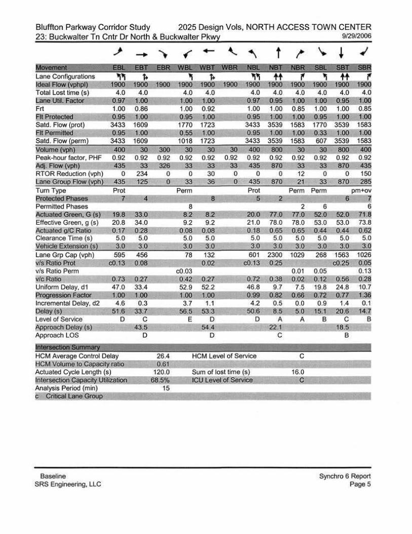
Bluffton Parkway Corridor Study 2025 Design Vols, NORTH ACCESS TOWN CENTER 23: Buckwalter Tn Cntr Dr North & Buckwalter Pk~ 9/29/2006 ,. - "').
MOV8Mri J ;g E8R Lane Configurations f> ld@ FlOWjVj)J;.jil) 1900 Total Lost time (s) 4.0 l:iiii:UJd,.Ea§i!!~; £00 Frt 0.86 Elt.frotected 100 Satd. Flow (prot) 1609 at.f'ennTtted .00 Satd. Flow (perm} 1609 Volume (VII!] 400 30 iK!Q Peak-hour factor, PHF 0.92 0.92 0.92 Mj. Flow Vilh.l 435 33 ~'§ RTOR Reduction (vph) 0 234 0 Lane GrouE! Flow (vph) 435 125 0 Tum Type Prot Protect!!(l~s 7 4 Permitted Phases ~tuated Green, G (s 19.8 33.0 Effective Green, g (s) 20.8 34.0 Actuated grc Ratio 0.17 0.28 Clearance Time (s) 5.0 5.0 Vehicle Extensi<>n (s} 3.0 3.0 Lane Grp Cap (vph) 595 456 vf§.fiayo P.m! r<.QJ.3_ 0.08 v/s Ratio Perm ~t c.Ba.tio _ o. 3 027 Uniform Delay, d1 47.0 33.4 !;!tQgression FactQ:t. 1.00 1.00 Incremental Delay, d2 4.6 0.3 Detay{s) 51.6 33.7 Level or Service D c [lpprolJ.ch Delay ( s} 43.5 Approach LOS D
!mersecaon 5tmmaiY ' HCM Average Control Delay 26.4 fiCM Volume tQ.Capac•ty ratjo Q.§l Actuated Cycle Length (s) 120.0 tntersectjofi.Cae£ty1Jli!@tjon §§.§% Analysis Period (min) 15
c ~<;;U!i¥!!1 bi!ll!! ~f.2\IP.
Baseline SRS Engineering, LLC
{" - ' ~ t ~
1900
1723 .00
1723
~Q 3Q 30 400 ,aog 0.92 0.92 0.92 0.92 0.92
~~ 33 33 435 870 i!3 0 30 0 0 0 12
33 36 0 435 870 21 Perm Prot Perm
5 2 2
20.0 77.0 77.0 21.0 78.0 78.0 0.18 0.65 0.65 5.0 5.0 5.0 3.0 3.0 3.0
78 132 601 2300 1029 0.02 !iW g'§
c0.03 0.01 0.42 0.27 o,z:g 0,38_ 0.02 52.9 52.2 46.8 9.7 7.5 1.QO 1.00 .99 0.82 0.66 3.7 1.1 4 .2 0.5 0.0
56.5 53.3 50.6 8.5 5.0 E D D A A
54.4 ;22 .1 D c
HCM Level of Service c
Sum of lost time (s) 16.0 lg!,!IeveJ:2f S.l!odc!!
~ + .; SBT?jSBR ++ r'
1900 1900 190i! '
4.0 4.0 4.0 00
1.00 0.85 J,OO~l.OO
3539 1583 1.00 .00
3539 1583
~ !!QO iOO 0.92 0.92 0.92 ~3 ~zo 435 0 0 150
33 870 285 Perm pm+ov
6 11 6 6
52.0 52.0 71.1i 53.0 53.0 73.8 0 .44 0.44 0.6~
5.0 5.0 5.0 3.0 3.0 3.11
268 1563 1026 9Jgg o.Q~
0.05 0.13 0.12. 0.56 0.~§ 19.8 24.8 10.7 0.72 0.77 J,3a 0.9 1.4 0.1
15.1- 20.6 l~ ~ B c B
18.5 B
]
Synchro 6 Report PageS

Bluffton Parl<way Corridor Study 2025 Design Vols, NORTH ACCESS TOWN CENTER 7: Bluffton Pkwy Phase 4 & Buckwalter Pkwy 9/29/2006
-" - ~ - t 'It'( 'It 'f'l'ltt '{''Itt'(
1900 1900 190() 1900 1900 1900 1900 1900 900~ 19QO 190Q 4.0 4.0 4.0 4.0 4.0 4.0 4.0 4.0 4.0 4.0 4.0 4.0 .00 00 00 00 .97 0.95 1.00 00 95 1.00
230 15 9ZO 25 25__ 2 1250 680 15 15 820 80 0.92 0.92 0.92 0.92 0.92 0.92 0.92 0.92 0.92 0.92 0.92 0.92 200 16 1054 27.: ~ 21 1359 739 16 16 891 all
0 0 4 0 022 0 0 4 0 050 250 6 1050 27 27 5 1359 739 12 16 891 31j
Perm pm+ov Perm Perm Prot Perm Perm Perm 4 5 8 5 2 6
Permitted Phases 4 4 8 2 6 6 Actuated Green, G (s) 21.0 21.0 74.0 21.0 21.0 53.0 89.0 89.0 31.0 31 .0~ Effective Green, g (s} 22.0 22.0 76.0 22.0 22.0 54.0 90.0 90.0 32.0 32.0 32.0 ~uated g/C Ratio 0.18 0.18 0.63 0.18 0.18 0.45 0.75 0.75 0.27 0.27 0~ Clearance Time (s} 5.0 5.0 5.0 5.0 5.0 5.0 5.0 5.0 5.0 5.0 5.0 rJ"""efiicle Extension (s) 3.0 3.0 3.0 3.0 3.0 3.0 3.0 3.0 3.0 3.0 3.0 Lane Grp Cap (vph) 253 342 1055 255 342 290 1545 2654 1187 184 944 422 ~~~Ra!iO. ET21 0.0] c03 5 g,Ql g~~ Q,, 1 a!-~~ v/s Ratio Perm 0.18 0.22 0.02 0.00 0.01 0.02 0.02 :tl!i Bat~ Q.99_ 0.05 J.OO 0.11 0.0~ 0.§§ 0,6.~ Q.Ql Q.Og 2-ii 0.0~ Uniform Delay, d1 48.9 40.4 21.8 40.8 40.1 30.0 4.7 3.8 33.0 43.1 33.0
~ssiOiifactot J.OO 1.00 1.00 1.00 J.OO J OO J.OO l.: _ o.ao o.82 Q.§g Incremental Delay, d2 52.7 0.1 26.4 0.2 0.0 0.9 18.1 0.4
~ili.J 101.6 40~4 4S.2 41.0 3,8 ;:o.2 Level of Service F D D D A c ~[oach pelay ~~ 58.2 ~5.Q Approach LOS E c !i'itiiiiiiliOiisummary J HCM Average Control Delay 40.5 l'fCMVol!Lm o Callaci_!Y ratio Actuated Cycle Length (s) I!J!~m;tioc.Capacity:utiliiatl!!!l Analysis Period (min)
li ~r.ilirsil biDLgr~~
Baseline SRS Engineering, LLC
Q~8 120.0 Sum of lost time ( s)
96J~ ICu....LevAI R[ §~ 15
8.0 E I
Synchro 6 Report Page 3
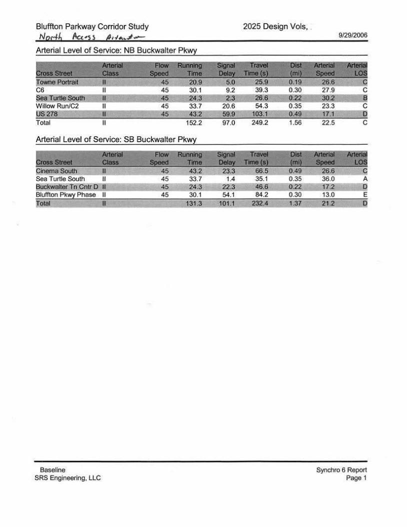
Bluffton Parkway Corridor Study
Nacib Acuss AI'!#\~~-
Sea Turtle" South Willow Run/C2 05278 Total II 152.2
Arterial Level of Service: SB Buckwalter Pkwl
AiJi!tifj FlOW Ri.ii:illlii9 Clas$ Speed l1me
Cinema South II 45 43.2 Sea Turtle South II 45 33.7 Buckwalter Tn Cntr 0 II 45 24.3 Bluffton Pk~ Phase II 45 30.1 iTotal II 131 .3
Baseline SRS Engineering, LLC
2025 Design Vols, .
97.0
= 23.3 1.4
22.3 54.1 01.1 g~~ J.37
9/29/2006
22.5
26.6 c 36.0 A 17.2 0 13.0 E 2 2 D
Synchro 6 Report Page 1

• •