Embed Size (px)
Citation preview
Introducing composite material in car bonnet
Alternative structures with respect to pedestrian safety
By
J. Schulz
H. Kalay
Diploma work no. 174/2016
At Department of Materials and Manufacturing Technology
CHALMERS UNIVERSITY OF TECHNOLOGY
Gothenburg, Sweden
Diploma work in the Master programme Materials Engineering
Performed at: Volvo Car Corporation
Volvo Jacobs väg PV4A, SE-405 31 Göteborg, Sweden
Supervisor: Erik Rydberg
Volvo Car Corporation
Volvo Jacobs väg PV4A, SE-405 31 Göteborg, Sweden
Examiner: Antal Boldizar
Department of Materials and Manufacturing Technology
Chalmers University of Technology, SE - 412 96 Gothenburg
Introducing composite material in car bonnet
Alternative structures with respect to pedestrian safety
JOHAN R. SCHULZ
HAKAN I. KALAY
© JOHAN R. SCHULZ, 2016.
© HAKAN I. KALAY, 2016.
Diploma work no 174/2016
Department of Materials and Manufacturing Technology
Chalmers University of Technology
SE-412 96 Gothenburg
Sweden
Telephone + 46 (0)31-772 1000
I
Introducing composite material in car bonnet
Alternative structures with respect to pedestrian safety
JOHAN R. SCHULZ
HAKAN I. KALAY
Department of Materials and Manufacturing Technology
Chalmers University of Technology
Abstract
The cars of today tend to be quite heavy in the front meanwhile light in the rear, mainly due to
the location of the engine compartment and powertrain in the front of the car. If the front weight
of the car could be reduced, the car could be more balanced and also the most discussed
parameter for cars, namely emission of carbon dioxide, can be reduced,. This study aims to
investigate how to introduce a composite materials in the bonnet, with the focus on reducing
the weight, while meeting important demands on the bonnet. In this study it was chosen to
consider the demands related to pedestrian safety and the stiffness of the bonnet. Pedestrian
safety is a complex demand saying that the bonnet should be able to absorb a certain amount
of energy from a head impact without getting the pedestrian injured. From an extensive
literature study three potential material structures were found to be appropriate regarding
impact resistance and flexural stiffness. Carbon fibre reinforced epoxy
(CFRP)/Polyvinylchloride (PVC) foam sandwich material, aluminium/polycarbonate
sandwich material and Hybrix micro-sandwich material are the materials explored in the
literature study to be appropriate candidates for the demands chosen in this study. As seen in
recent research based on simulations of impact resistance, some materials are especially
interesting. Considering those more interesting materials, it was decided to purchase and build
beam sections of each material sharing the same geometry to perform impact tests in the drop
tower facility at Volvo Cars Corporation (VCC) in Gothenburg. Of those three materials
selected only two materials could be compiled due to the time limit of the project. The material
excluded from testing was the Al/PC sandwich material. In additional to the potential stiff and
impact resistant materials, also an aluminium beam was built sharing the same geometry as the
other materials and the impact resistance and stiffness of samples were measured and compared
with the aluminium material used in the current bonnets at VCC. Additional to the impact tests,
also a three point bending test was performed on the different materials samples according to
VCC and ASTM standards, in order to determine the stiffness of the structures studied. The
results showed that the CFRP/PVC foam sandwich material absorbed least amount of energy
at the impact test. The amount of energy absorbed was only in the elastic region of the material,
but the structure did not have the ability to deform plastically. It was interesting to note that
this kind of structure indicated a possibility to reduce weight, by approximately 24 % lighter
than the current aluminium material. The Hybrix material combined with steel absorbed most
amount of energy but was 27 % heavier than the current aluminium material. Finally, the three
point bending showed that the aluminium structure had the highest stiffness of the samples
studied.
Keywords: Bonnet, Pedestrian safety, HIC, Stiffness, Energy absorption, CFRP, sandwich material
II
Preface
After almost spending 5 months (January 18th – June 10th) to perform this study we have
concluded that the learning outcome in form of industrial experience and coordination working
within R&D projects has been great. We are glad to have the great opportunity to perform this
thesis work at Volvo Cars and achieve experience into the industry when we now will be kicked
out to the jungle of engineering.
We would like to thank our supervisor and examiner Professor Antal Boldizar at Chalmers for
superior guidance and support on our path through the academic and industrial jungle. We
would also like to thank our supervisor Erik Rydberg at Volvo Cars for giving us the
opportunity to perform the study at Volvo at the same time as providing us with support. Other
people involved in this thesis we would like to thank is Anders Fredriksson, Per Heintz, Oskar
Sjöstedt, Marcus Sylvin, Henrik Molker, Sreten Tabakovic, Björn Börjesson, Reino Frykberg,
Per Mårtensson, Tekin Cihan and the rest of the group of exterior front for supporting us in this
endurance.
Johan Schulz Hakan Kalay
III
Table of Contents
1 INTRODUCING COMPOSITE MATERIALS IN CAR
BONNET ...................................................................... 1
1.1 Background ........................................................................................................................... 1
1.2 Purpose................................................................................................................................... 1
1.3 Limitation .............................................................................................................................. 1
1.4 Definition of the issue ............................................................................................................ 1
1.5 Method ................................................................................................................................... 2
2 BACKGROUND........................................................ 3
2.1 Conventional car bonnets ..................................................................................................... 3
2.2 Bonnet Section ....................................................................................................................... 3
2.3 Bonnet complete .................................................................................................................... 3
2.4 Requirements on the bonnet ................................................................................................ 4
2.4.1 Pedestrian Safety Test ......................................................................................... 5
2.4.2 Passive safety ....................................................................................................... 8
2.4.3 Stiffness requirements......................................................................................... 8
2.5 Benchmarking ....................................................................................................................... 9
2.6 Composite Materials ........................................................................................................... 12
2.6.1 Characteristics of composites (FRPs) .............................................................. 12
2.7 Crashworthiness of composites .......................................................................................... 13
2.7.1 Fibre type ........................................................................................................... 14
2.7.2 Matrix Type ....................................................................................................... 14
2.7.3 Fibre Architecture ............................................................................................. 15
2.7.4 Fibre Volume Fraction ..................................................................................... 15
2.8 Sandwich materials ............................................................................................................. 15
2.8.1 Honeycomb Structural core .............................................................................. 16
2.8.2 Foam Structural Core ....................................................................................... 17
2.8.3 Potential impact resistant sandwich materials ................................................. 17
2.9 CES ....................................................................................................................................... 19
2.9.1 Fracture Toughness vs. Young Modulus ......................................................... 19
2.9.2 Tensile Strength vs. Density.............................................................................. 20
2.9.3 Young modulus vs. Density ............................................................................... 20
2.9.4 Summary............................................................................................................ 21
IV
2.10 Classical Laminate Theory in Matlab ............................................................................... 21
3 EXPERIMENTAL ................................................... 22
3.1 Procedure ............................................................................................................................. 22
3.2 Material candidates ............................................................................................................ 22
3.2.1 Aluminium (reference material) ....................................................................... 22
3.2.2 CRFP/PVC foam ............................................................................................... 23
3.2.3 Hybrix ................................................................................................................ 23
3.2.4 Al/PC.................................................................................................................. 24
3.3 Physical testing – Impact test ............................................................................................. 24
3.3.1 Bending test ....................................................................................................... 25
3.4 Simulation of reference material in LS-DYNA ................................................................ 25
3.4.1 Configuration 1 ................................................................................................. 26
3.4.2 Configuration 2 ................................................................................................. 26
3.4.3 Configuration 3 ................................................................................................. 27
3.4.4 Configuration 4 ................................................................................................. 27
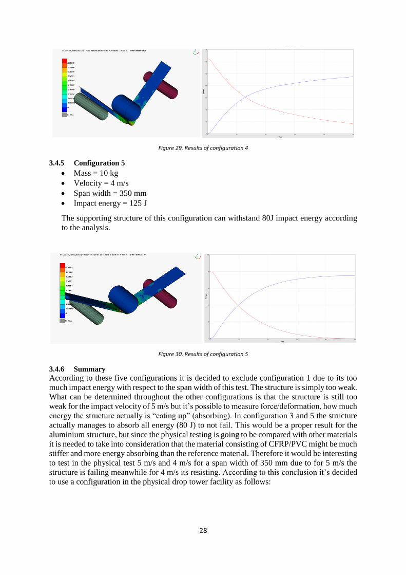
3.4.5 Configuration 5 ................................................................................................. 28
3.4.6 Summary............................................................................................................ 28
4 RESULTS .............................................................. 30
4.1 Drop tower ........................................................................................................................... 30
4.1.1 Aluminium ......................................................................................................... 31
4.1.2 CFRP/PVC foam sandwich .............................................................................. 33
4.1.3 Hybrix/Steel ....................................................................................................... 34
4.1.4 Summary of drop tower tests ............................................................................ 35
4.2 Three point bending test ..................................................................................................... 37
5 DISCUSSION ......................................................... 40
6 CONCLUSION ....................................................... 41
6.1 Recommendations ............................................................................................................... 41
7 REFERENCES ....................................................... 44
V
Table of Figures
Figure 1. Inner bonnet structure of V526 ................................................................................... 4
Figure 2. Inner bonnet structure ................................................................................................. 4
Figure 3. Crash impact testing of Car Bonnet at 40 km/h, A is head impact, B is leg impact
and C is lower leg impact testing ............................................................................................... 5
Figure 4. Illustrating the shape of head impact mass ................................................................. 6
Figure 5. Fatality risks versus HIC values (Yoshida et al., 1999) [2]........................................ 7
Figure 6. Crash impact testing of Volvo XC90 ......................................................................... 7
Figure 7. Functional requirement description ............................................................................ 8
Figure 8. Demands of passive safety (Crash) ............................................................................ 8
Figure 9. Results of materials used in bonnets ........................................................................ 10
Figure 10. Pedestrian safety results from EuroNCAP BMW i3 [28] ...................................... 10
Figure 11. Pedestrian safety results from EuroNCAP Renault Twingo [28] ........................... 11
Figure 12. Pedestrian safety results from EuroNCAP Volvo XC90 [28] ................................ 11
Figure 13. Picture of Aston Martin V12 Vanquish Centenary Edition where the outer bonnet
is made of aluminium............................................................................................................... 11
Figure 14. Visualizing the inner bonnet made CFRP .............................................................. 12
Figure 15. Illustrating the orthotropic directions ..................................................................... 13
Figure 16. Illustration of relationship of material orientation and coordinate system ............. 13
Figure 17. Changing in mechanical properties by replacing the glass fiber with carbon fiber.
A is micro hardness, B is UTS, C is yield strength, D is ductility [16] ................................... 14
Figure 18. Different sandwich core types [19] ........................................................................ 16
Figure 19. Representing the structure of Hybrix [18] .............................................................. 18
Figure 20. Fracture toughness vs. Young modulus.................................................................. 20
Figure 21. Tensile Strength vs. Density ................................................................................... 20
Figure 22. Young’s Modulus vs. Density ................................................................................ 21
Figure 23. Visualizing the geometry of the beam section for AL specimen ........................... 23
Figure 24. Representing the hardening curve of Aluminium AA6016-T6, Superlite 200IH
from Aleris that is used into LS-DYNA .................................................................................. 25
Figure 25. Illustration of the simulation in LS-DYNA. Representing the support widths ...... 26
Figure 26. Results of Configuration 1...................................................................................... 26
Figure 27. Results of configuration 2 ...................................................................................... 27
Figure 28. Results of configuration 3 ...................................................................................... 27
Figure 29. Results of configuration 4 ...................................................................................... 28
Figure 30. Results of configuration 5 ...................................................................................... 28
Figure 31. Visualizing the different beams made of aluminium, CFRP/PVC foam sandwich
and Hybrix/steel. ...................................................................................................................... 30
Figure 32. Visualizing the drop tower "rig 2". ......................................................................... 31
Figure 33. Before and after picture of one aluminium beam subjected to an impact velocity of
5 m/s ......................................................................................................................................... 31
Figure 34. Before and after picture of one aluminium beam subjected to an impact velocity of
4 m/s ......................................................................................................................................... 32
Figure 35. Force variation of aluminium beams ...................................................................... 32
Figure 36. Visualizing before and after impact of CFRP/PVC foam sandwich material ........ 33
Figure 37. Force distribution for CFRP/PVC foam sandwich beams ...................................... 33
Figure 38. Visualizing before and after impact of Hybrix/steel beam ..................................... 34
VI
Figure 39. Force distribution of the Hybrix beam ................................................................... 34
Figure 40. Comparison of the different materials subjected to the impact test. Each curve is
an average of each material series in the testing. Black line is CFRP/PVC foam sandwich
material, Blue line is Hybrix/Steel and Red line is the aluminium material ............................ 36
Figure 41. Force/displacement/Energy curves for the different materials ............................... 37
Figure 42. Shape factor and simply supported beam centre load of current design. Δ, E, P, L
and I describes deflection, flexural modulus, force (load), Length of beam and moment of
inertia of bending axis respectively. ........................................................................................ 38
Figure 43. Stiffness result of CFRP/PVC sandwich material, Hybrix/Steel beam, Aluminium
beam and CFRP/PVC foam sandwich rectangular samples .................................................... 38
Figure 44. Stiffness results of inner and outer aluminium stiffness samples combined, outer
aluminium stiffness sample single and inner aluminium stiffness sample single ................... 39
Figure 45. CFRP/Soric sandwich material............................................................................... 42
Figure 46. Energy curves of all materials including CFRP/Soric ............................................ 42
Tables
Table 1. The mass variation of the different samples subjected to the impact test.................. 30
Table 2. Measurement and equipment data ............................................................................. 35
Table 3. The result of 3 point bending testing for aluminium, composite and Hybrix material.
.................................................................................................................................................. 38
Equations
Equation 1. Head Injury Criteria equation ................................................................................. 6
Equation 2. [A], [B] and [D] matrices belonging to Classical laminate theory ....................... 13
Equation 3. Material indices for fracture toughness ................................................................ 19
Equation 4. Material indices for flexural stiffness ................................................................... 19
Equation 5. Calculating kinetic energy .................................................................................... 24
Equation 6. Calculation new velocity ...................................................................................... 24
1
1 Introducing composite materials in car bonnet This chapter is describing the thesis work and why it’s relevant for Volvo Cars Corporation.
This followed by a definition of issue and method for the work.
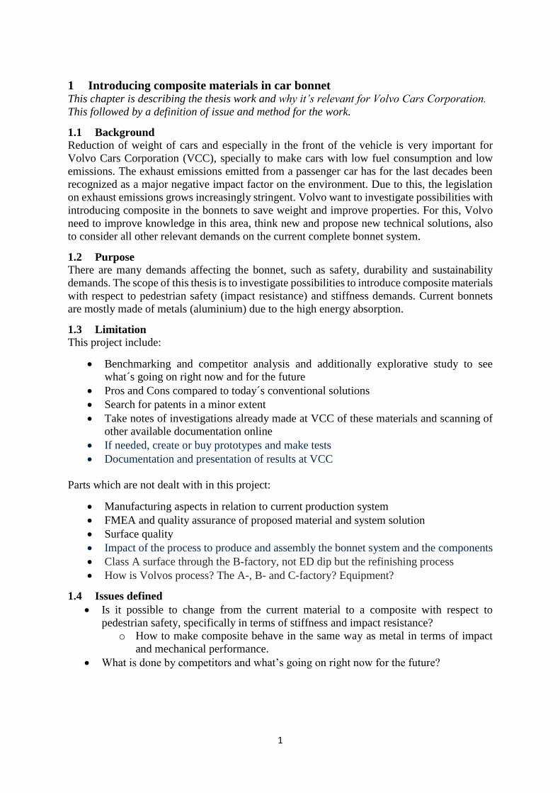
1.1 Background
Reduction of weight of cars and especially in the front of the vehicle is very important for
Volvo Cars Corporation (VCC), specially to make cars with low fuel consumption and low
emissions. The exhaust emissions emitted from a passenger car has for the last decades been
recognized as a major negative impact factor on the environment. Due to this, the legislation
on exhaust emissions grows increasingly stringent. Volvo want to investigate possibilities with
introducing composite in the bonnets to save weight and improve properties. For this, Volvo
need to improve knowledge in this area, think new and propose new technical solutions, also
to consider all other relevant demands on the current complete bonnet system.
1.2 Purpose
There are many demands affecting the bonnet, such as safety, durability and sustainability
demands. The scope of this thesis is to investigate possibilities to introduce composite materials
with respect to pedestrian safety (impact resistance) and stiffness demands. Current bonnets
are mostly made of metals (aluminium) due to the high energy absorption.
1.3 Limitation
This project include:
Benchmarking and competitor analysis and additionally explorative study to see
what´s going on right now and for the future
Pros and Cons compared to today´s conventional solutions
Search for patents in a minor extent
Take notes of investigations already made at VCC of these materials and scanning of
other available documentation online
If needed, create or buy prototypes and make tests
Documentation and presentation of results at VCC
Parts which are not dealt with in this project:
Manufacturing aspects in relation to current production system
FMEA and quality assurance of proposed material and system solution
Surface quality
Impact of the process to produce and assembly the bonnet system and the components
Class A surface through the B-factory, not ED dip but the refinishing process
How is Volvos process? The A-, B- and C-factory? Equipment?
1.4 Issues defined
Is it possible to change from the current material to a composite with respect to
pedestrian safety, specifically in terms of stiffness and impact resistance?
o How to make composite behave in the same way as metal in terms of impact
and mechanical performance.
What is done by competitors and what’s going on right now for the future?
2
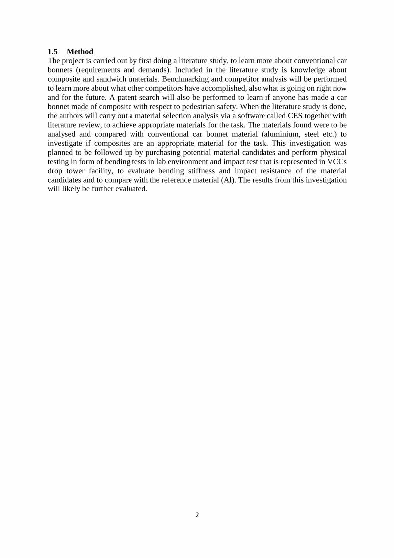
1.5 Method
The project is carried out by first doing a literature study, to learn more about conventional car
bonnets (requirements and demands). Included in the literature study is knowledge about
composite and sandwich materials. Benchmarking and competitor analysis will be performed
to learn more about what other competitors have accomplished, also what is going on right now
and for the future. A patent search will also be performed to learn if anyone has made a car
bonnet made of composite with respect to pedestrian safety. When the literature study is done,
the authors will carry out a material selection analysis via a software called CES together with
literature review, to achieve appropriate materials for the task. The materials found were to be
analysed and compared with conventional car bonnet material (aluminium, steel etc.) to
investigate if composites are an appropriate material for the task. This investigation was
planned to be followed up by purchasing potential material candidates and perform physical
testing in form of bending tests in lab environment and impact test that is represented in VCCs
drop tower facility, to evaluate bending stiffness and impact resistance of the material
candidates and to compare with the reference material (Al). The results from this investigation
will likely be further evaluated.
3
2 Background This chapter is describing necessary theory regarding the conventional bonnet and the
critical demands influencing the bonnet. A benchmark program is introduced to seek out
what’s already on the market followed by a definition of composite materials. Within
composite materials, crashworthiness of composite materials is investigated followed by
introducing sandwich materials. A separate chapter about CES material selector is
introduced to screen out and find appropriate composite materials for the work. The last
chapter of this section is about introducing classical laminate theory into Matlab to learn
about the behaviour of composite materials.
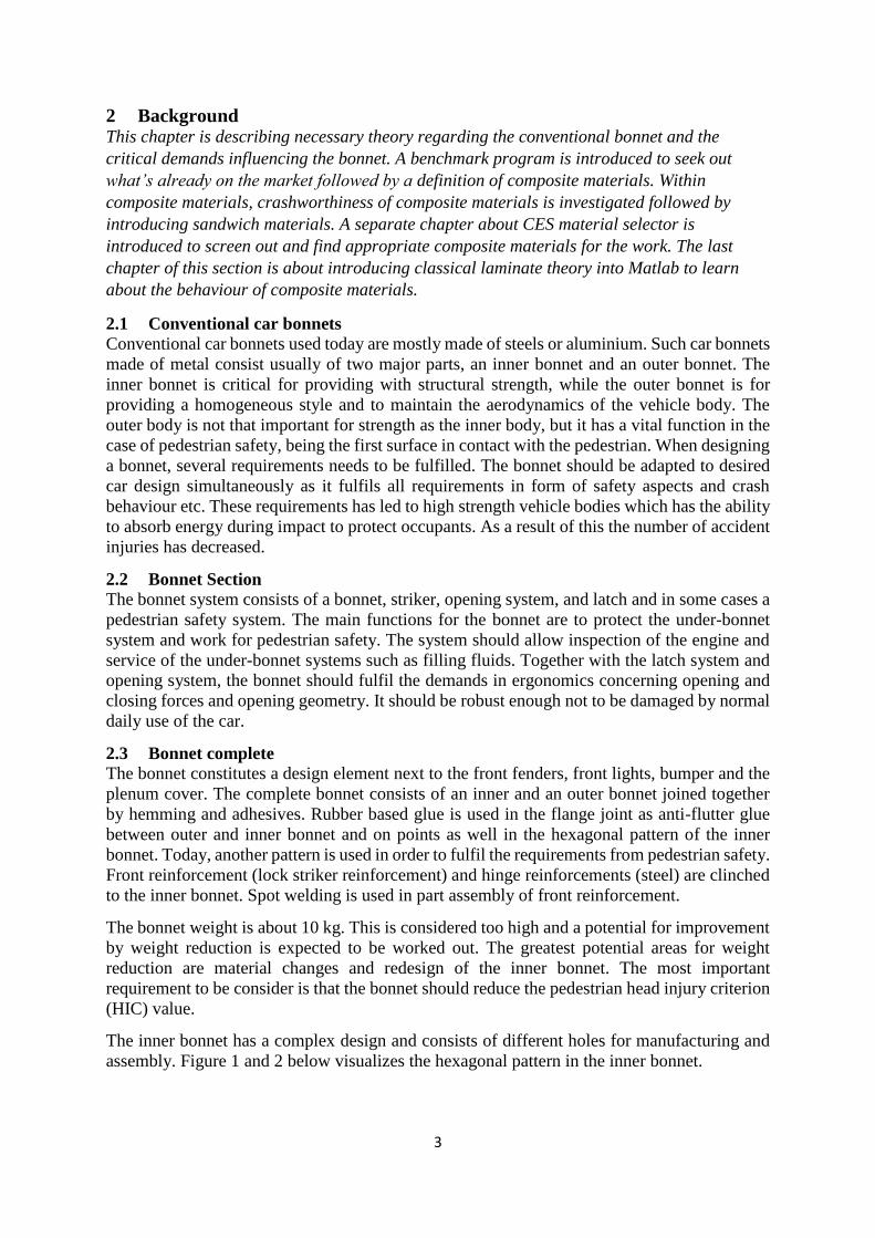
2.1 Conventional car bonnets
Conventional car bonnets used today are mostly made of steels or aluminium. Such car bonnets
made of metal consist usually of two major parts, an inner bonnet and an outer bonnet. The
inner bonnet is critical for providing with structural strength, while the outer bonnet is for
providing a homogeneous style and to maintain the aerodynamics of the vehicle body. The
outer body is not that important for strength as the inner body, but it has a vital function in the
case of pedestrian safety, being the first surface in contact with the pedestrian. When designing
a bonnet, several requirements needs to be fulfilled. The bonnet should be adapted to desired
car design simultaneously as it fulfils all requirements in form of safety aspects and crash
behaviour etc. These requirements has led to high strength vehicle bodies which has the ability
to absorb energy during impact to protect occupants. As a result of this the number of accident
injuries has decreased.
2.2 Bonnet Section
The bonnet system consists of a bonnet, striker, opening system, and latch and in some cases a
pedestrian safety system. The main functions for the bonnet are to protect the under-bonnet
system and work for pedestrian safety. The system should allow inspection of the engine and
service of the under-bonnet systems such as filling fluids. Together with the latch system and
opening system, the bonnet should fulfil the demands in ergonomics concerning opening and
closing forces and opening geometry. It should be robust enough not to be damaged by normal
daily use of the car.
2.3 Bonnet complete
The bonnet constitutes a design element next to the front fenders, front lights, bumper and the
plenum cover. The complete bonnet consists of an inner and an outer bonnet joined together
by hemming and adhesives. Rubber based glue is used in the flange joint as anti-flutter glue
between outer and inner bonnet and on points as well in the hexagonal pattern of the inner
bonnet. Today, another pattern is used in order to fulfil the requirements from pedestrian safety.
Front reinforcement (lock striker reinforcement) and hinge reinforcements (steel) are clinched
to the inner bonnet. Spot welding is used in part assembly of front reinforcement.
The bonnet weight is about 10 kg. This is considered too high and a potential for improvement
by weight reduction is expected to be worked out. The greatest potential areas for weight
reduction are material changes and redesign of the inner bonnet. The most important
requirement to be consider is that the bonnet should reduce the pedestrian head injury criterion
(HIC) value.
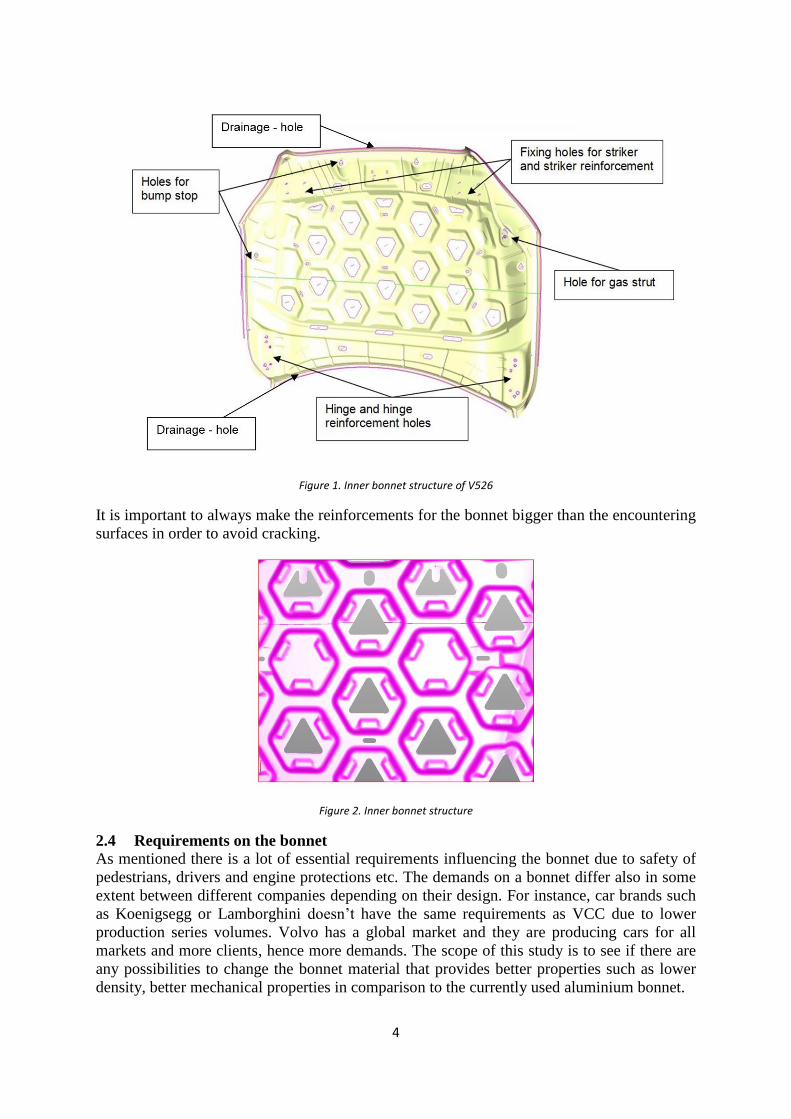
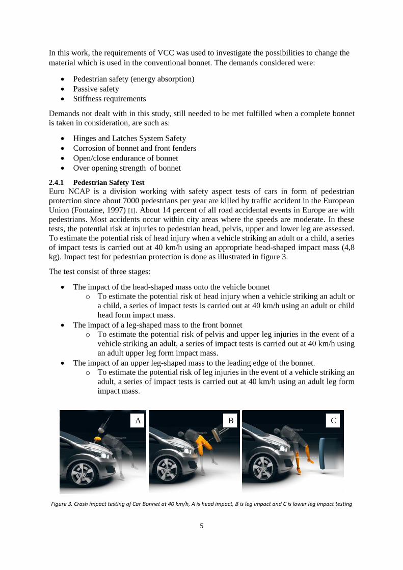
The inner bonnet has a complex design and consists of different holes for manufacturing and
assembly. Figure 1 and 2 below visualizes the hexagonal pattern in the inner bonnet.
4
Figure 1. Inner bonnet structure of V526
It is important to always make the reinforcements for the bonnet bigger than the encountering
surfaces in order to avoid cracking.
Figure 2. Inner bonnet structure
2.4 Requirements on the bonnet
As mentioned there is a lot of essential requirements influencing the bonnet due to safety of
pedestrians, drivers and engine protections etc. The demands on a bonnet differ also in some
extent between different companies depending on their design. For instance, car brands such
as Koenigsegg or Lamborghini doesn’t have the same requirements as VCC due to lower
production series volumes. Volvo has a global market and they are producing cars for all
markets and more clients, hence more demands. The scope of this study is to see if there are
any possibilities to change the bonnet material that provides better properties such as lower
density, better mechanical properties in comparison to the currently used aluminium bonnet.
5
In this work, the requirements of VCC was used to investigate the possibilities to change the
material which is used in the conventional bonnet. The demands considered were:
Pedestrian safety (energy absorption)
Passive safety
Stiffness requirements
Demands not dealt with in this study, still needed to be met fulfilled when a complete bonnet
is taken in consideration, are such as:
Hinges and Latches System Safety
Corrosion of bonnet and front fenders
Open/close endurance of bonnet
Over opening strength of bonnet
2.4.1 Pedestrian Safety Test
Euro NCAP is a division working with safety aspect tests of cars in form of pedestrian
protection since about 7000 pedestrians per year are killed by traffic accident in the European
Union (Fontaine, 1997) [1]. About 14 percent of all road accidental events in Europe are with
pedestrians. Most accidents occur within city areas where the speeds are moderate. In these
tests, the potential risk at injuries to pedestrian head, pelvis, upper and lower leg are assessed.
To estimate the potential risk of head injury when a vehicle striking an adult or a child, a series
of impact tests is carried out at 40 km/h using an appropriate head-shaped impact mass (4,8
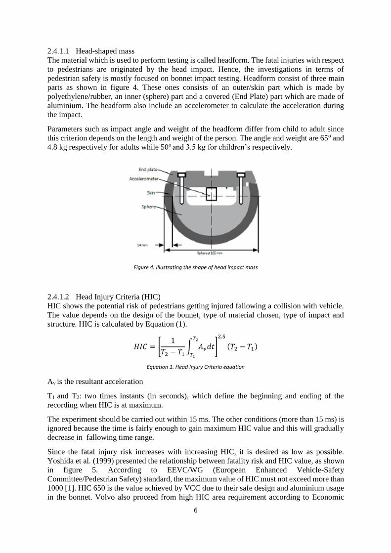
kg). Impact test for pedestrian protection is done as illustrated in figure 3.
The test consist of three stages:
The impact of the head-shaped mass onto the vehicle bonnet
o To estimate the potential risk of head injury when a vehicle striking an adult or
a child, a series of impact tests is carried out at 40 km/h using an adult or child
head form impact mass.
The impact of a leg-shaped mass to the front bonnet
o To estimate the potential risk of pelvis and upper leg injuries in the event of a
vehicle striking an adult, a series of impact tests is carried out at 40 km/h using
an adult upper leg form impact mass.
The impact of an upper leg-shaped mass to the leading edge of the bonnet.
o To estimate the potential risk of leg injuries in the event of a vehicle striking an
adult, a series of impact tests is carried out at 40 km/h using an adult leg form
impact mass.
Figure 3. Crash impact testing of Car Bonnet at 40 km/h, A is head impact, B is leg impact and C is lower leg impact testing
A C B
6
2.4.1.1 Head-shaped mass
The material which is used to perform testing is called headform. The fatal injuries with respect
to pedestrians are originated by the head impact. Hence, the investigations in terms of
pedestrian safety is mostly focused on bonnet impact testing. Headform consist of three main
parts as shown in figure 4. These ones consists of an outer/skin part which is made by
polyethylene/rubber, an inner (sphere) part and a covered (End Plate) part which are made of
aluminium. The headform also include an accelerometer to calculate the acceleration during
the impact.
Parameters such as impact angle and weight of the headform differ from child to adult since
this criterion depends on the length and weight of the person. The angle and weight are 65o and
4.8 kg respectively for adults while 50o and 3.5 kg for children’s respectively.
Figure 4. Illustrating the shape of head impact mass
2.4.1.2 Head Injury Criteria (HIC)
HIC shows the potential risk of pedestrians getting injured fallowing a collision with vehicle.
The value depends on the design of the bonnet, type of material chosen, type of impact and
structure. HIC is calculated by Equation (1).
𝐻𝐼𝐶 = [1
𝑇2 − 𝑇1∫ 𝐴𝑣𝑑𝑡
𝑇2
𝑇1
]
2.5
(𝑇2 − 𝑇1)
Equation 1. Head Injury Criteria equation
Av is the resultant acceleration
T1 and T2: two times instants (in seconds), which define the beginning and ending of the
recording when HIC is at maximum.
The experiment should be carried out within 15 ms. The other conditions (more than 15 ms) is
ignored because the time is fairly enough to gain maximum HIC value and this will gradually
decrease in fallowing time range.
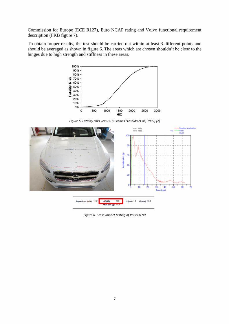
Since the fatal injury risk increases with increasing HIC, it is desired as low as possible.
Yoshida et al. (1999) presented the relationship between fatality risk and HIC value, as shown
in figure 5. According to EEVC/WG (European Enhanced Vehicle-Safety
Committee/Pedestrian Safety) standard, the maximum value of HIC must not exceed more than
1000 [1]. HIC 650 is the value achieved by VCC due to their safe design and aluminium usage
in the bonnet. Volvo also proceed from high HIC area requirement according to Economic
7
Commission for Europe (ECE R127), Euro NCAP rating and Volvo functional requirement
description (FKB figure 7).
To obtain proper results, the test should be carried out within at least 3 different points and
should be averaged as shown in figure 6. The areas which are chosen shouldn’t be close to the
hinges due to high strength and stiffness in these areas.
Figure 5. Fatality risks versus HIC values (Yoshida et al., 1999) [2]
Figure 6. Crash impact testing of Volvo XC90
8
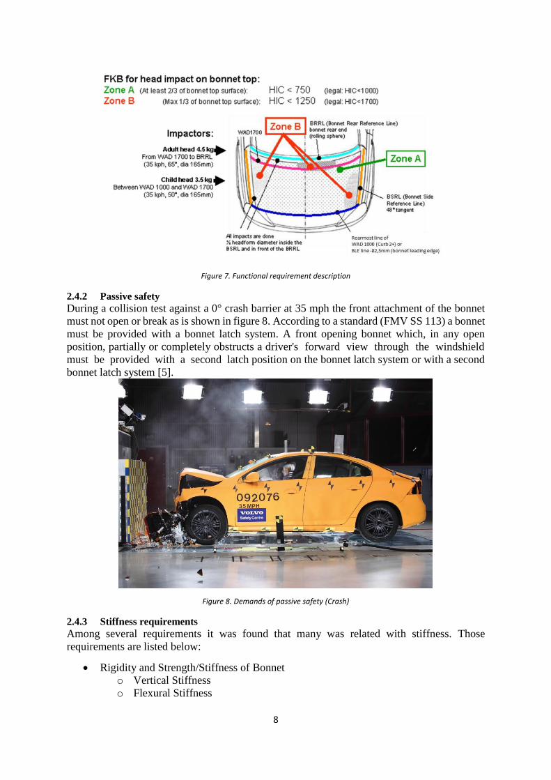
Figure 7. Functional requirement description
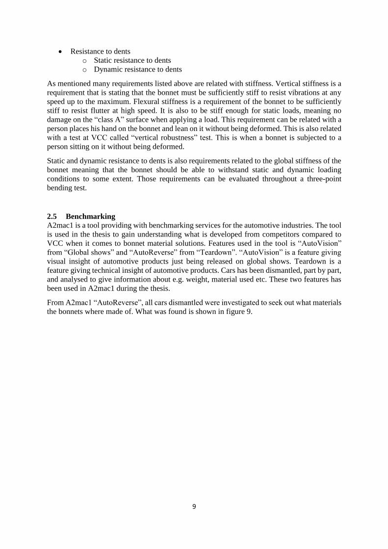
2.4.2 Passive safety
During a collision test against a 0° crash barrier at 35 mph the front attachment of the bonnet
must not open or break as is shown in figure 8. According to a standard (FMV SS 113) a bonnet
must be provided with a bonnet latch system. A front opening bonnet which, in any open
position, partially or completely obstructs a driver's forward view through the windshield
must be provided with a second latch position on the bonnet latch system or with a second
bonnet latch system [5].
Figure 8. Demands of passive safety (Crash)
2.4.3 Stiffness requirements
Among several requirements it was found that many was related with stiffness. Those
requirements are listed below:
Rigidity and Strength/Stiffness of Bonnet
o Vertical Stiffness
o Flexural Stiffness
9
Resistance to dents
o Static resistance to dents
o Dynamic resistance to dents
As mentioned many requirements listed above are related with stiffness. Vertical stiffness is a
requirement that is stating that the bonnet must be sufficiently stiff to resist vibrations at any
speed up to the maximum. Flexural stiffness is a requirement of the bonnet to be sufficiently
stiff to resist flutter at high speed. It is also to be stiff enough for static loads, meaning no
damage on the “class A” surface when applying a load. This requirement can be related with a
person places his hand on the bonnet and lean on it without being deformed. This is also related
with a test at VCC called “vertical robustness” test. This is when a bonnet is subjected to a
person sitting on it without being deformed.
Static and dynamic resistance to dents is also requirements related to the global stiffness of the
bonnet meaning that the bonnet should be able to withstand static and dynamic loading
conditions to some extent. Those requirements can be evaluated throughout a three-point
bending test.
2.5 Benchmarking
A2mac1 is a tool providing with benchmarking services for the automotive industries. The tool
is used in the thesis to gain understanding what is developed from competitors compared to
VCC when it comes to bonnet material solutions. Features used in the tool is “AutoVision”
from “Global shows” and “AutoReverse” from “Teardown”. “AutoVision” is a feature giving
visual insight of automotive products just being released on global shows. Teardown is a
feature giving technical insight of automotive products. Cars has been dismantled, part by part,
and analysed to give information about e.g. weight, material used etc. These two features has
been used in A2mac1 during the thesis.
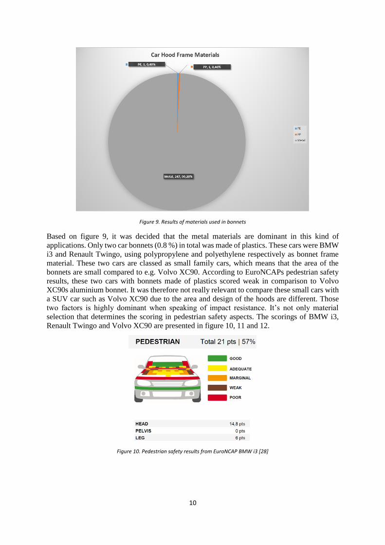
From A2mac1 “AutoReverse”, all cars dismantled were investigated to seek out what materials
the bonnets where made of. What was found is shown in figure 9.
10
Figure 9. Results of materials used in bonnets
Based on figure 9, it was decided that the metal materials are dominant in this kind of
applications. Only two car bonnets (0.8 %) in total was made of plastics. These cars were BMW
i3 and Renault Twingo, using polypropylene and polyethylene respectively as bonnet frame
material. These two cars are classed as small family cars, which means that the area of the
bonnets are small compared to e.g. Volvo XC90. According to EuroNCAPs pedestrian safety
results, these two cars with bonnets made of plastics scored weak in comparison to Volvo
XC90s aluminium bonnet. It was therefore not really relevant to compare these small cars with
a SUV car such as Volvo XC90 due to the area and design of the hoods are different. Those
two factors is highly dominant when speaking of impact resistance. It’s not only material
selection that determines the scoring in pedestrian safety aspects. The scorings of BMW i3,
Renault Twingo and Volvo XC90 are presented in figure 10, 11 and 12.
Figure 10. Pedestrian safety results from EuroNCAP BMW i3 [28]
11
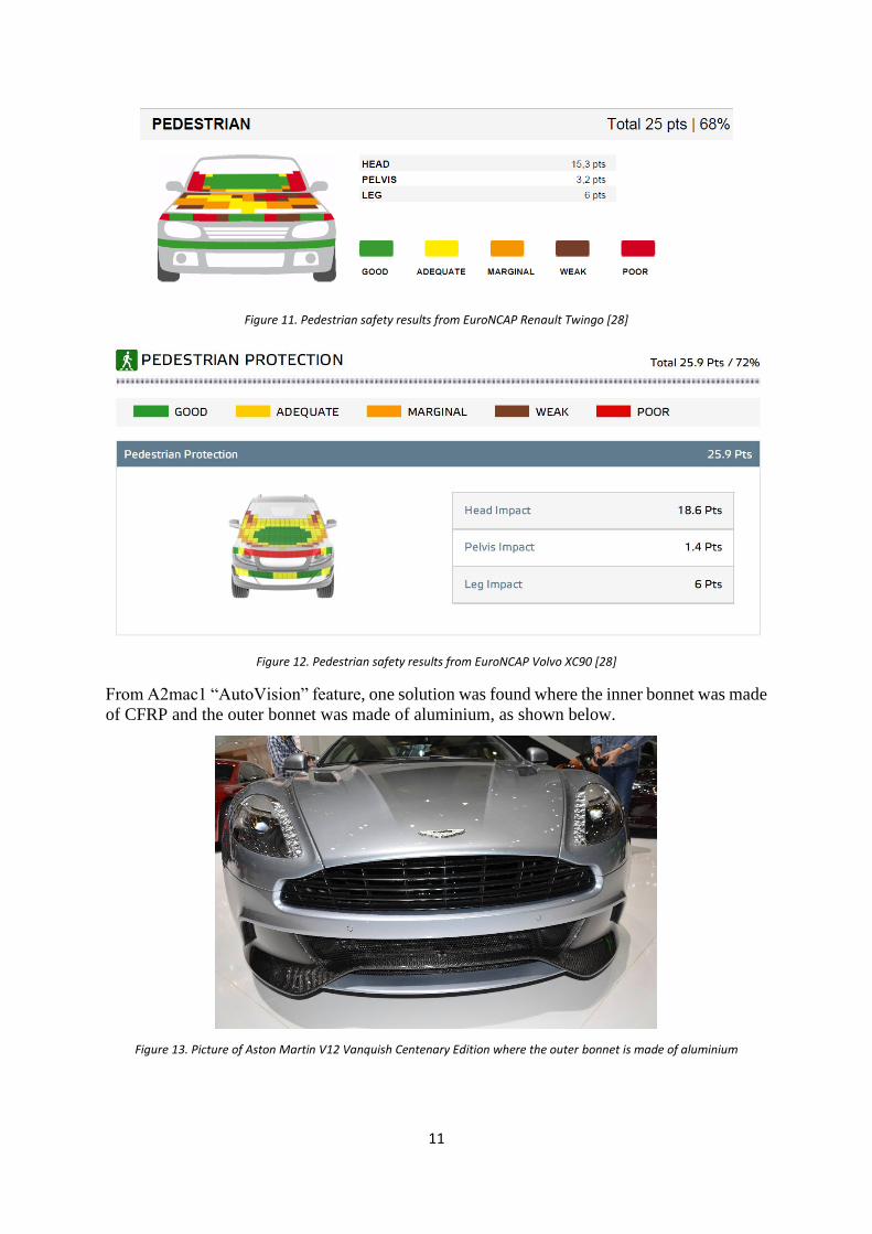
Figure 11. Pedestrian safety results from EuroNCAP Renault Twingo [28]
Figure 12. Pedestrian safety results from EuroNCAP Volvo XC90 [28]
From A2mac1 “AutoVision” feature, one solution was found where the inner bonnet was made
of CFRP and the outer bonnet was made of aluminium, as shown below.
Figure 13. Picture of Aston Martin V12 Vanquish Centenary Edition where the outer bonnet is made of aluminium
12
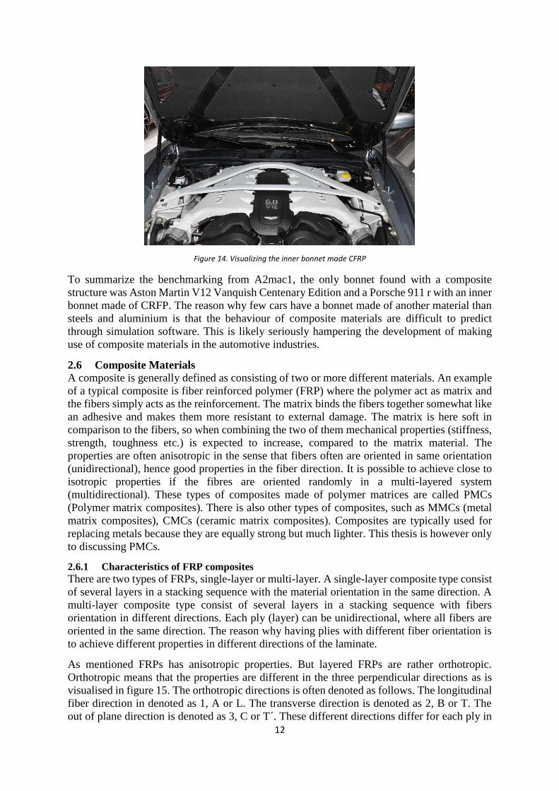
Figure 14. Visualizing the inner bonnet made CFRP
To summarize the benchmarking from A2mac1, the only bonnet found with a composite
structure was Aston Martin V12 Vanquish Centenary Edition and a Porsche 911 r with an inner
bonnet made of CRFP. The reason why few cars have a bonnet made of another material than
steels and aluminium is that the behaviour of composite materials are difficult to predict
through simulation software. This is likely seriously hampering the development of making
use of composite materials in the automotive industries.
2.6 Composite Materials
A composite is generally defined as consisting of two or more different materials. An example
of a typical composite is fiber reinforced polymer (FRP) where the polymer act as matrix and
the fibers simply acts as the reinforcement. The matrix binds the fibers together somewhat like
an adhesive and makes them more resistant to external damage. The matrix is here soft in
comparison to the fibers, so when combining the two of them mechanical properties (stiffness,
strength, toughness etc.) is expected to increase, compared to the matrix material. The
properties are often anisotropic in the sense that fibers often are oriented in same orientation
(unidirectional), hence good properties in the fiber direction. It is possible to achieve close to
isotropic properties if the fibres are oriented randomly in a multi-layered system
(multidirectional). These types of composites made of polymer matrices are called PMCs
(Polymer matrix composites). There is also other types of composites, such as MMCs (metal
matrix composites), CMCs (ceramic matrix composites). Composites are typically used for
replacing metals because they are equally strong but much lighter. This thesis is however only
to discussing PMCs.
2.6.1 Characteristics of FRP composites
There are two types of FRPs, single-layer or multi-layer. A single-layer composite type consist
of several layers in a stacking sequence with the material orientation in the same direction. A
multi-layer composite type consist of several layers in a stacking sequence with fibers
orientation in different directions. Each ply (layer) can be unidirectional, where all fibers are
oriented in the same direction. The reason why having plies with different fiber orientation is
to achieve different properties in different directions of the laminate.
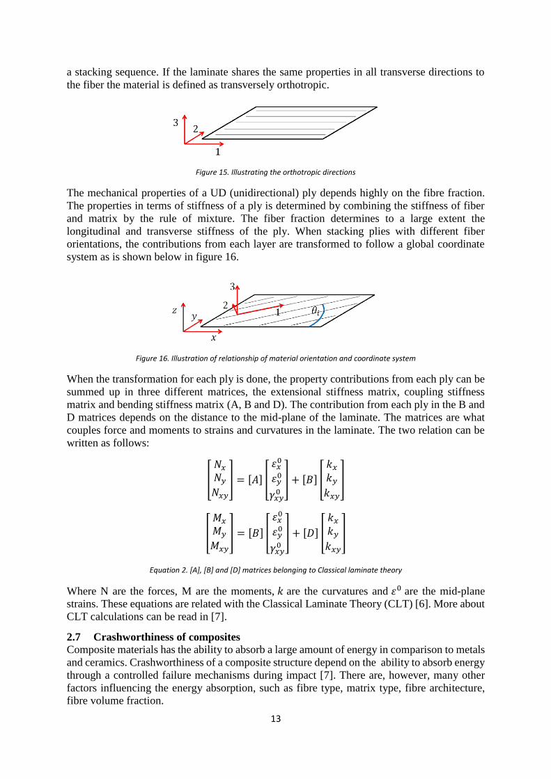
As mentioned FRPs has anisotropic properties. But layered FRPs are rather orthotropic.
Orthotropic means that the properties are different in the three perpendicular directions as is
visualised in figure 15. The orthotropic directions is often denoted as follows. The longitudinal
fiber direction in denoted as 1, A or L. The transverse direction is denoted as 2, B or T. The
out of plane direction is denoted as 3, C or T´. These different directions differ for each ply in
13
a stacking sequence. If the laminate shares the same properties in all transverse directions to
the fiber the material is defined as transversely orthotropic.
Figure 15. Illustrating the orthotropic directions
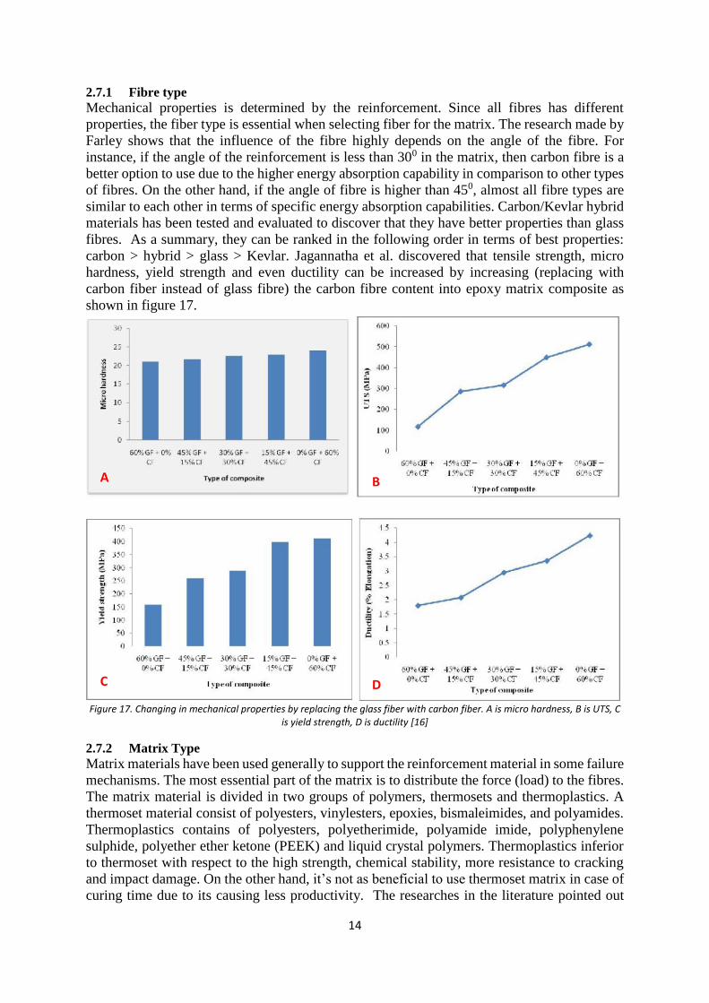
The mechanical properties of a UD (unidirectional) ply depends highly on the fibre fraction.
The properties in terms of stiffness of a ply is determined by combining the stiffness of fiber
and matrix by the rule of mixture. The fiber fraction determines to a large extent the
longitudinal and transverse stiffness of the ply. When stacking plies with different fiber
orientations, the contributions from each layer are transformed to follow a global coordinate
system as is shown below in figure 16.
Figure 16. Illustration of relationship of material orientation and coordinate system
When the transformation for each ply is done, the property contributions from each ply can be
summed up in three different matrices, the extensional stiffness matrix, coupling stiffness
matrix and bending stiffness matrix (A, B and D). The contribution from each ply in the B and
D matrices depends on the distance to the mid-plane of the laminate. The matrices are what
couples force and moments to strains and curvatures in the laminate. The two relation can be
written as follows:
[
𝑁𝑥
𝑁𝑦
𝑁𝑥𝑦
] = [𝐴] [
𝜀𝑥0
𝜀𝑦0
𝛾𝑥𝑦0
] + [𝐵] [
𝑘𝑥
𝑘𝑦
𝑘𝑥𝑦
]
[
𝑀𝑥
𝑀𝑦
𝑀𝑥𝑦
] = [𝐵] [
𝜀𝑥0
𝜀𝑦0
𝛾𝑥𝑦0
] + [𝐷] [
𝑘𝑥
𝑘𝑦
𝑘𝑥𝑦
]
Equation 2. [A], [B] and [D] matrices belonging to Classical laminate theory
Where N are the forces, M are the moments, 𝑘 are the curvatures and 𝜀0 are the mid-plane
strains. These equations are related with the Classical Laminate Theory (CLT) [6]. More about
CLT calculations can be read in [7].
2.7 Crashworthiness of composites
Composite materials has the ability to absorb a large amount of energy in comparison to metals
and ceramics. Crashworthiness of a composite structure depend on the ability to absorb energy
through a controlled failure mechanisms during impact [7]. There are, however, many other
factors influencing the energy absorption, such as fibre type, matrix type, fibre architecture,
fibre volume fraction.
14
2.7.1 Fibre type
Mechanical properties is determined by the reinforcement. Since all fibres has different
properties, the fiber type is essential when selecting fiber for the matrix. The research made by
Farley shows that the influence of the fibre highly depends on the angle of the fibre. For
instance, if the angle of the reinforcement is less than 300 in the matrix, then carbon fibre is a
better option to use due to the higher energy absorption capability in comparison to other types
of fibres. On the other hand, if the angle of fibre is higher than 450, almost all fibre types are
similar to each other in terms of specific energy absorption capabilities. Carbon/Kevlar hybrid
materials has been tested and evaluated to discover that they have better properties than glass
fibres. As a summary, they can be ranked in the following order in terms of best properties:
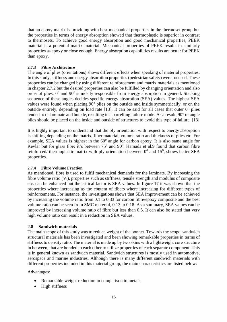
carbon > hybrid > glass > Kevlar. Jagannatha et al. discovered that tensile strength, micro
hardness, yield strength and even ductility can be increased by increasing (replacing with
carbon fiber instead of glass fibre) the carbon fibre content into epoxy matrix composite as
shown in figure 17.
Figure 17. Changing in mechanical properties by replacing the glass fiber with carbon fiber. A is micro hardness, B is UTS, C
is yield strength, D is ductility [16]
2.7.2 Matrix Type
Matrix materials have been used generally to support the reinforcement material in some failure
mechanisms. The most essential part of the matrix is to distribute the force (load) to the fibres.
The matrix material is divided in two groups of polymers, thermosets and thermoplastics. A
thermoset material consist of polyesters, vinylesters, epoxies, bismaleimides, and polyamides.
Thermoplastics contains of polyesters, polyetherimide, polyamide imide, polyphenylene
sulphide, polyether ether ketone (PEEK) and liquid crystal polymers. Thermoplastics inferior
to thermoset with respect to the high strength, chemical stability, more resistance to cracking
and impact damage. On the other hand, it’s not as beneficial to use thermoset matrix in case of
curing time due to its causing less productivity. The researches in the literature pointed out
A
C
B
D
15
that an epoxy matrix is providing with best mechanical properties in the thermoset group but
the properties in terms of energy absorption showed that thermoplastic is superior in contrast
to thermosets. To achieve good energy absorption and good mechanical properties, PEEK
material is a potential matrix material. Mechanical properties of PEEK results in similarly
properties as epoxy or close enough. Energy absorption capabilities results are better for PEEK
than epoxy.
2.7.3 Fibre Architecture
The angle of plies (orientations) shows different effects when speaking of material properties.
In this study, stiffness and energy absorption properties (pedestrian safety) were focused. These
properties can be changed by using different reinforcement and matrix materials as mentioned
in chapter 2.7.2 but the desired properties can also be fulfilled by changing orientation and also
order of plies. 00 and 900 is mostly responsible from energy absorption in general. Stacking
sequence of these angles decides specific energy absorption (SEA) values. The highest SEA
values were found when placing 90° plies on the outside and inside symmetrically, or on the
outside entirely, depending on load rate [13]. It can be said for all cases that outer 0° plies
tended to delaminate and buckle, resulting in a barrelling failure mode. As a result, 90° or angle
plies should be placed on the inside and outside of structures to avoid this type of failure. [13]
It is highly important to understand that the ply orientation with respect to energy absorption
is shifting depending on the matrix, fiber material, volume ratio and thickness of plies etc. For
example, SEA values is highest in the 600 angle for carbon epoxy. It is also same angle for
Kevlar but for glass fibre it’s between 750 and 900. Hamada et al.9 found that carbon fibre
reinforced/ thermoplastic matrix with ply orientation between 00 and 150, shows better SEA
properties.
2.7.4 Fibre Volume Fraction
As mentioned, fibre is used to fulfil mechanical demands for the laminate. By increasing the
fibre volume ratio (Vf), properties such as stiffness, tensile strength and modulus of composite
etc. can be enhanced but the critical factor is SEA values. In figure 17 it was shown that the
properties where increasing as the content of fibers where increasing for different types of
reinforcements. For instance, the investigations shows that SEA improvement can be achieved
by increasing the volume ratio from 0.1 to 0.33 for carbon fibre/epoxy composite and the best
volume ratio can be seen from SMC material, 0.13 to 0.18. As a summary, SEA values can be
improved by increasing volume ratio of fibre but less than 0.5. It can also be stated that very
high volume ratio can result in a reduction in SEA values.
2.8 Sandwich materials
The main scope of this study was to reduce weight of the bonnet. Towards the scope, sandwich
structural materials has been investigated and been showing remarkable properties in terms of
stiffness to density ratio. The material is made up by two skins with a lightweight core structure
in between, that are bonded to each other to utilize properties of each separate component. This
is in general known as sandwich material. Sandwich structures is mostly used in automotive,
aerospace and marine industries. Although there is many different sandwich materials with
different properties included in this material group, the main characteristics are listed below:
Advantages:
Remarkable weight reduction in comparison to metals
High stiffness
16
Smooth surface (Class A surface)
Good thermal insulation and damping capacity
Cost efficiency
High energy absorption
Disadvantages:
Local load introduction
Complex joining with metallic surface
Some non-recyclable core material
High manufacturing cost for certain material
High water absorption in honeycomb and open-cell foam core
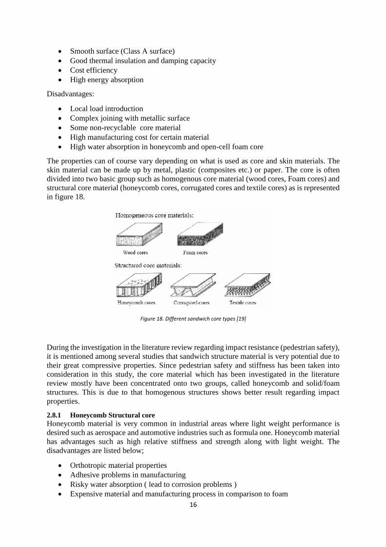
The properties can of course vary depending on what is used as core and skin materials. The
skin material can be made up by metal, plastic (composites etc.) or paper. The core is often
divided into two basic group such as homogenous core material (wood cores, Foam cores) and
structural core material (honeycomb cores, corrugated cores and textile cores) as is represented
in figure 18.
Figure 18. Different sandwich core types [19]
During the investigation in the literature review regarding impact resistance (pedestrian safety),
it is mentioned among several studies that sandwich structure material is very potential due to
their great compressive properties. Since pedestrian safety and stiffness has been taken into
consideration in this study, the core material which has been investigated in the literature
review mostly have been concentrated onto two groups, called honeycomb and solid/foam
structures. This is due to that homogenous structures shows better result regarding impact
properties.
2.8.1 Honeycomb Structural core
Honeycomb material is very common in industrial areas where light weight performance is
desired such as aerospace and automotive industries such as formula one. Honeycomb material
has advantages such as high relative stiffness and strength along with light weight. The
disadvantages are listed below;
Orthotropic material properties
Adhesive problems in manufacturing
Risky water absorption ( lead to corrosion problems )
Expensive material and manufacturing process in comparison to foam
17
Hard to produce 3-D shapes
2.8.2 Foam Structural Core
Foam structured material is the most common core material mentioned in the literature review
regarding impact/energy absorbing properties. The advantages and disadvantages are listed
below:
Advantages:
Easy to Produce 3D-Shapes
Higher Energy Absorption Capacity
Easy Repair in Case of Accidents
Excellent Thermal and Acoustical Insulation
Excellent Dampening Features
Higher cost efficiency in terms of manufacturing and material
Disadvantages:
Higher Specific Density than honeycomb cores
Poor Thermal Resistance / Poor Fire Rating in comparison with honeycomb material
Foam core structural material has been decided to investigate in this study due to the advantages
listed above [25], [26], and [27].
2.8.3 Potential impact resistant sandwich materials
Three potential material candidates were found during the literature review. Those materials
are listed below:
CFRP/PVC Foam sandwich material
Aluminium/polycarbonate sandwich material
HybrixTM – From Lamera AB
2.8.3.1 CFRP/PVC Foam
As it is described in chapter 2.7.2. , Two potential materials (PEEK and Epoxy) tended to be
the best matrix materials. Although PEEK had slightly better properties in comparison to epoxy
in terms of impact resistance and recyclability, epoxy was chosen. The reason for not selecting
PEEK is that it’s not as manufacture adapted as epoxy. The reinforcement selected was Carbon
fibre due to its good stiffness vs density properties.
Polystyrenes (PS), polyurethane (PE), Polyvinyl Chloride (PVC) and Polymethacrylimide
(PMI) are common materials for foam applications. PE and PVC tend to be a better option
among those materials in terms of impact resistance. Polyurethane is not environmentally
friendly and due to this Volvo cannot handle it. Therefore PVC material is selected to use as
core material in this study.
Testing of composite single plates (laminates) in terms of pedestrian safety can be found in the
work of Ahad Torkestani (2015), Azzam Ahmed (2016). This work showed that it is possible
to achieve lower HIC values than current aluminium bonnet by using composite skins. The
displacement between engine block and bonnet needs to be increased since it can reach at least
two times more than current distance. The displacement is simply the distance the bonnet can
deform in the z-direction after impact. [21, 3].
Y, Bahe-El-Din (2016), Azzam Ahmed (2016) investigated the composite sandwich material.
The result showed that the acceptable HIC and displacement values can be obtained by using
composite faces with foam core [22, 3].
18
To summarize those inputs and apply them to this study, Carbon fibre reinforced epoxy resin
with PVC foam core was selected. The orientation of the skins are selected as follows: [[0/90,
±45]2, 0/90, core, [0/90]4]. The ply orientation is based on the article made of Azzam Ahmed,
Li Wie, Inroduction CFRP as an alternative material for engine bonnet to achieve better
pedestrian safety using finite element modelling, Thin-Walled Structures [3].
2.8.3.2 Micro-sandwich materials and Hybrix
Micro-sandwich materials are very thin sandwich materials that can be related with the
behaviour of regular steel sheets but much lower weight. Micro-sandwich materials are usually
made by a polymeric soft core (as epoxy resins or rubber) covered by metallic skins. In some
cases the core also contain fibbers, metallic or not [20].
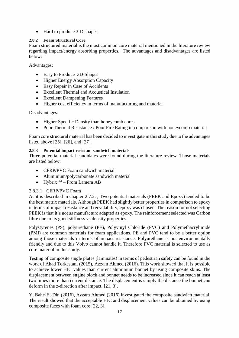
Hybrix is a material that is developed from a company named Lamera in Gothenburg, Sweden.
Hybrix is a metal micro-sandwich material that is very thin (0.7 – 2.1 mm). The characteristics
of this structure is strong and light. The structure consist of two thin foils of steel or aluminium
and a core that is hollow which contains air and microscopic fibres that bounds the faces
together with an epoxy resin which can be seen in figure 19 [18].
Figure 19. Representing the structure of Hybrix [18]
2.8.3.3 Aluminium/Polycarbonate
From an investigation about composite sandwich materials with respect to pedestrian safety for
car bonnets, a comparison of steel, aluminium and composite skins sharing the same core
material (PC) was investigated to select the best performing material in terms of pedestrian
safety. In this study, the authors were showing that if steel was replaced with a sandwich
material consisting of aluminium skins with a core made of solid polycarbonate it was possible
to reduce the HIC values drastically in comparison to a steel bonnet. This study was carried out
to reduce weight for a bonnet design consisting of steel. In reality the materials from this study
can’t really contribute with any weight reduction since the current bonnet is made of aluminium.
The aluminium bonnet consisting of a thickness of totally 2mm when consider inner and outer
19
bonnet combined. In this study the authors where assuming the skin thickness of 1 mm
aluminium each skin plus additional 3 mm solid PC material as a core. This means that this
particular material won’t really contribute any weight reduction in comparison to a pure
aluminium bonnet. But what makes this study highly interesting is the significantly low HIC
values achieved by the simulation.
2.9 CES A verification of composite materials have been performed in CES EduPack to ensure that the
CFRP chosen are proper. As it is discussed in the theory chapter, Energy absorption capacity
and material stiffness capability parameters are the most important properties. This test have
been based on those properties versus the density to carry out the test. To achieve proper results,
material indices have been applied for all properties to determine the best material for the task
by using Ashby, M.F (1999).
The indices of flexural properties were taken in consideration of a flat panel loaded in bending.
Other indices for energy absorption capability were taken in consideration of a beam condition.
The material indices for both cases are as follows [23], [24]:
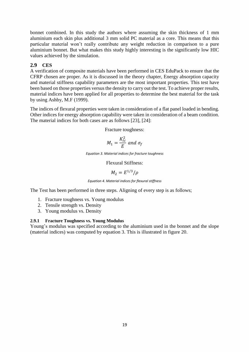
Fracture toughness:
𝑀1 =𝐾𝐼𝑐
2
𝐸 𝑎𝑛𝑑 𝜎𝑓
Equation 3. Material indices for fracture toughness
Flexural Stiffness:
𝑀2 = 𝐸1/3/𝜌
Equation 4. Material indices for flexural stiffness
The Test has been performed in three steps. Aligning of every step is as follows;
1. Fracture toughness vs. Young modulus
2. Tensile strength vs. Density
3. Young modulus vs. Density
2.9.1 Fracture Toughness vs. Young Modulus
Young’s modulus was specified according to the aluminium used in the bonnet and the slope
(material indices) was computed by equation 3. This is illustrated in figure 20.
20
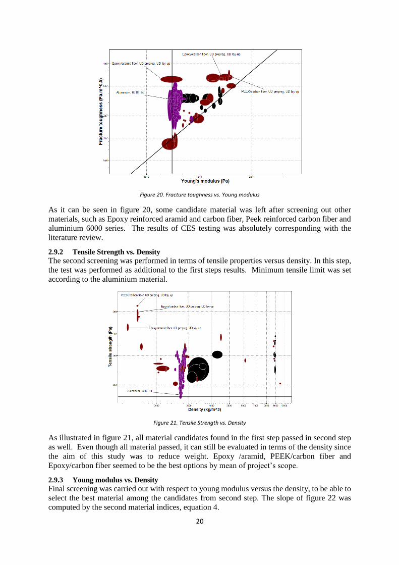
Figure 20. Fracture toughness vs. Young modulus
As it can be seen in figure 20, some candidate material was left after screening out other
materials, such as Epoxy reinforced aramid and carbon fiber, Peek reinforced carbon fiber and
aluminium 6000 series. The results of CES testing was absolutely corresponding with the
literature review.
2.9.2 Tensile Strength vs. Density
The second screening was performed in terms of tensile properties versus density. In this step,
the test was performed as additional to the first steps results. Minimum tensile limit was set
according to the aluminium material.
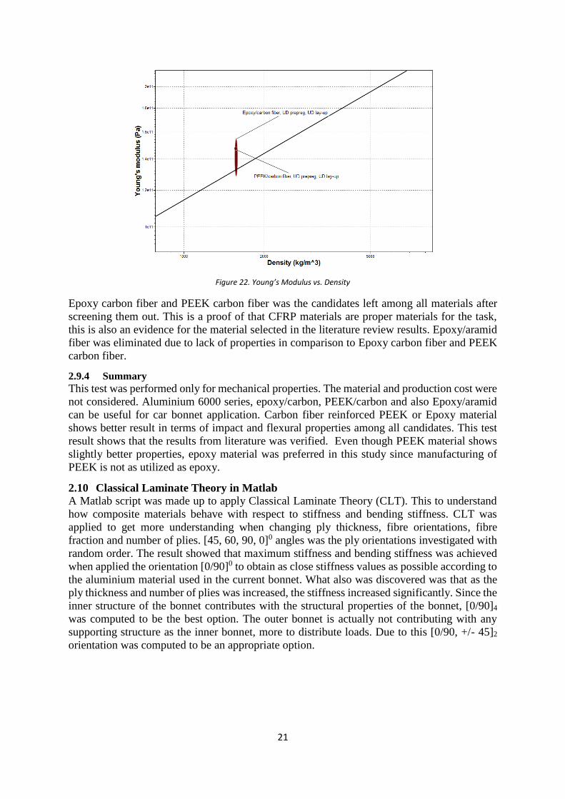
Figure 21. Tensile Strength vs. Density
As illustrated in figure 21, all material candidates found in the first step passed in second step
as well. Even though all material passed, it can still be evaluated in terms of the density since
the aim of this study was to reduce weight. Epoxy /aramid, PEEK/carbon fiber and
Epoxy/carbon fiber seemed to be the best options by mean of project’s scope.
2.9.3 Young modulus vs. Density
Final screening was carried out with respect to young modulus versus the density, to be able to
select the best material among the candidates from second step. The slope of figure 22 was
computed by the second material indices, equation 4.
21
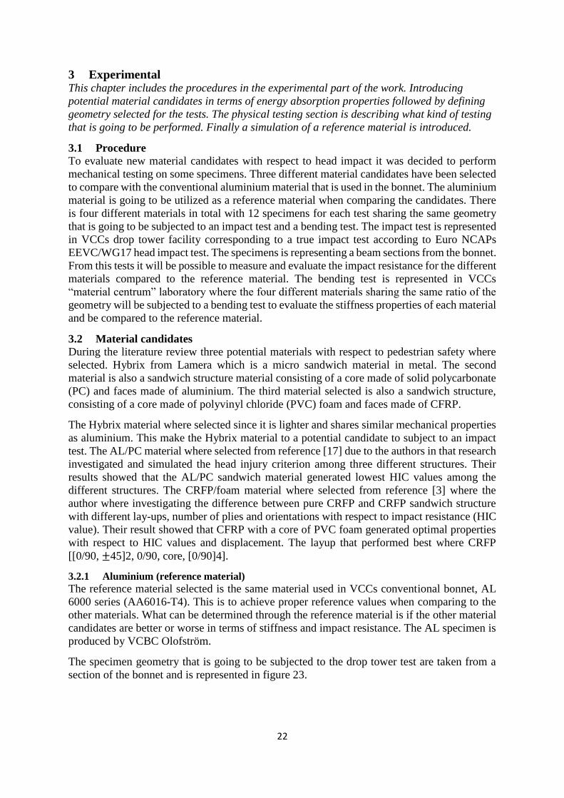
Figure 22. Young’s Modulus vs. Density
Epoxy carbon fiber and PEEK carbon fiber was the candidates left among all materials after
screening them out. This is a proof of that CFRP materials are proper materials for the task,
this is also an evidence for the material selected in the literature review results. Epoxy/aramid
fiber was eliminated due to lack of properties in comparison to Epoxy carbon fiber and PEEK
carbon fiber.
2.9.4 Summary
This test was performed only for mechanical properties. The material and production cost were
not considered. Aluminium 6000 series, epoxy/carbon, PEEK/carbon and also Epoxy/aramid
can be useful for car bonnet application. Carbon fiber reinforced PEEK or Epoxy material
shows better result in terms of impact and flexural properties among all candidates. This test
result shows that the results from literature was verified. Even though PEEK material shows
slightly better properties, epoxy material was preferred in this study since manufacturing of
PEEK is not as utilized as epoxy.
2.10 Classical Laminate Theory in Matlab
A Matlab script was made up to apply Classical Laminate Theory (CLT). This to understand
how composite materials behave with respect to stiffness and bending stiffness. CLT was
applied to get more understanding when changing ply thickness, fibre orientations, fibre
fraction and number of plies. [45, 60, 90, 0]0 angles was the ply orientations investigated with
random order. The result showed that maximum stiffness and bending stiffness was achieved
when applied the orientation [0/90]0 to obtain as close stiffness values as possible according to
the aluminium material used in the current bonnet. What also was discovered was that as the
ply thickness and number of plies was increased, the stiffness increased significantly. Since the
inner structure of the bonnet contributes with the structural properties of the bonnet, [0/90]4
was computed to be the best option. The outer bonnet is actually not contributing with any
supporting structure as the inner bonnet, more to distribute loads. Due to this [0/90, +/- 45]2
orientation was computed to be an appropriate option.
22
3 Experimental This chapter includes the procedures in the experimental part of the work. Introducing
potential material candidates in terms of energy absorption properties followed by defining
geometry selected for the tests. The physical testing section is describing what kind of testing
that is going to be performed. Finally a simulation of a reference material is introduced.
3.1 Procedure
To evaluate new material candidates with respect to head impact it was decided to perform
mechanical testing on some specimens. Three different material candidates have been selected
to compare with the conventional aluminium material that is used in the bonnet. The aluminium
material is going to be utilized as a reference material when comparing the candidates. There
is four different materials in total with 12 specimens for each test sharing the same geometry
that is going to be subjected to an impact test and a bending test. The impact test is represented
in VCCs drop tower facility corresponding to a true impact test according to Euro NCAPs
EEVC/WG17 head impact test. The specimens is representing a beam sections from the bonnet.
From this tests it will be possible to measure and evaluate the impact resistance for the different
materials compared to the reference material. The bending test is represented in VCCs
“material centrum” laboratory where the four different materials sharing the same ratio of the
geometry will be subjected to a bending test to evaluate the stiffness properties of each material
and be compared to the reference material.
3.2 Material candidates
During the literature review three potential materials with respect to pedestrian safety where
selected. Hybrix from Lamera which is a micro sandwich material in metal. The second
material is also a sandwich structure material consisting of a core made of solid polycarbonate
(PC) and faces made of aluminium. The third material selected is also a sandwich structure,
consisting of a core made of polyvinyl chloride (PVC) foam and faces made of CFRP.
The Hybrix material where selected since it is lighter and shares similar mechanical properties
as aluminium. This make the Hybrix material to a potential candidate to subject to an impact
test. The AL/PC material where selected from reference [17] due to the authors in that research
investigated and simulated the head injury criterion among three different structures. Their
results showed that the AL/PC sandwich material generated lowest HIC values among the
different structures. The CRFP/foam material where selected from reference [3] where the
author where investigating the difference between pure CRFP and CRFP sandwich structure
with different lay-ups, number of plies and orientations with respect to impact resistance (HIC
value). Their result showed that CFRP with a core of PVC foam generated optimal properties
with respect to HIC values and displacement. The layup that performed best where CRFP
[[0/90, ±45]2, 0/90, core, [0/90]4].
3.2.1 Aluminium (reference material)
The reference material selected is the same material used in VCCs conventional bonnet, AL
6000 series (AA6016-T4). This is to achieve proper reference values when comparing to the
other materials. What can be determined through the reference material is if the other material
candidates are better or worse in terms of stiffness and impact resistance. The AL specimen is
produced by VCBC Olofström.
The specimen geometry that is going to be subjected to the drop tower test are taken from a
section of the bonnet and is represented in figure 23.
23
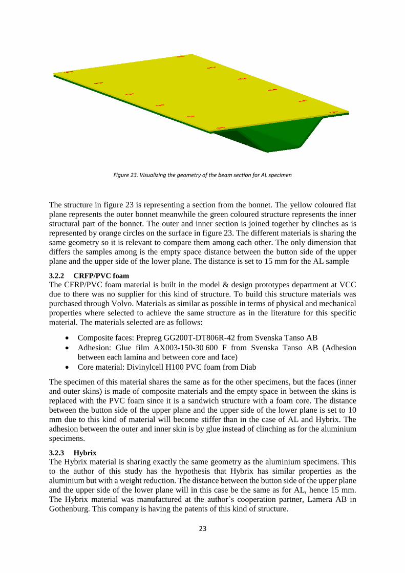
Figure 23. Visualizing the geometry of the beam section for AL specimen
The structure in figure 23 is representing a section from the bonnet. The yellow coloured flat
plane represents the outer bonnet meanwhile the green coloured structure represents the inner
structural part of the bonnet. The outer and inner section is joined together by clinches as is
represented by orange circles on the surface in figure 23. The different materials is sharing the
same geometry so it is relevant to compare them among each other. The only dimension that
differs the samples among is the empty space distance between the button side of the upper
plane and the upper side of the lower plane. The distance is set to 15 mm for the AL sample
3.2.2 CRFP/PVC foam
The CFRP/PVC foam material is built in the model & design prototypes department at VCC
due to there was no supplier for this kind of structure. To build this structure materials was
purchased through Volvo. Materials as similar as possible in terms of physical and mechanical
properties where selected to achieve the same structure as in the literature for this specific
material. The materials selected are as follows:
Composite faces: Prepreg GG200T-DT806R-42 from Svenska Tanso AB
Adhesion: Glue film AX003-150-30 600 F from Svenska Tanso AB (Adhesion
between each lamina and between core and face)
Core material: Divinylcell H100 PVC foam from Diab
The specimen of this material shares the same as for the other specimens, but the faces (inner
and outer skins) is made of composite materials and the empty space in between the skins is
replaced with the PVC foam since it is a sandwich structure with a foam core. The distance
between the button side of the upper plane and the upper side of the lower plane is set to 10
mm due to this kind of material will become stiffer than in the case of AL and Hybrix. The
adhesion between the outer and inner skin is by glue instead of clinching as for the aluminium
specimens.
3.2.3 Hybrix
The Hybrix material is sharing exactly the same geometry as the aluminium specimens. This
to the author of this study has the hypothesis that Hybrix has similar properties as the
aluminium but with a weight reduction. The distance between the button side of the upper plane
and the upper side of the lower plane will in this case be the same as for AL, hence 15 mm.
The Hybrix material was manufactured at the author’s cooperation partner, Lamera AB in
Gothenburg. This company is having the patents of this kind of structure.
24
The beams was created by Lamera to make as close material properties as in aluminium. Thus,
upper part was decided to consist of Hybrix material in a total the thickness of 1,4mm by using
0,15mm stainless steel faces and under part was made by solid stainless steel in the thickness
of 0,7mm stainless steel sheet. Worth to mention about this kind of structure is that the
combination of steel and Hybrix is not conventional, it’s a highly experimental candidate that
is going to be investigated with respect to energy absorption capabilities.
3.2.4 Al/PC
The Al/PC material should consist of the same geometry as the CFRP/PVC foam material but
it is decided to be removed from the test due to the long lead time to order such thin skins as
desired. The thickness desired was set to 0.5 mm for each skin and the lead time was up to 12
weeks. Due to the lack of time it was decided to exclude this material from the testing but it
should be included in the final evaluation of the results. On the other hand this material
wouldn’t decrease the weight due to the thickness of the faces would be the same as for the AL
material plus additional core material in form of PC. This would generate significant more
weight but maybe with improved properties. What is highly interesting with this kind of
structure would be to investigate if the HIC values could be decreased as the author of that
study claimed. This would be a very potential material to decrease HIC values.
3.3 Physical testing – Impact test
The impact test is carried out to seek out how much energy the different material can absorb.
This can be related to a true head impact test on a bonnet, but with magnified beam sections.
During this test, the HIC values are not of interest, rather energy absorption/deformation to
seek out how the different materials performs versus the reference material. As mentioned the
impact test is performed in VCCs drop tower facility where a cylinder is going to be dropped
on the beam section which simply is supported between two supports with a distance of 350
mm. A true adult head impact test is carried out with a cylinder-like head form with a mass of
4.8 kg at a speed with 40 km/h at impact. The drop tower facility request a minimum mass of
10 kg for the impact mass since it needs to be attached to a rig which also contain a mass. This
means that the kinetic energy (U) needs to be recalculated as follows:
𝑈 =𝑚1𝑉1
2
2=
4,8 ∗ (403,6)2
2= 296,3 𝐽
Equation 5. Calculating kinetic energy
With mass = 10 kg:
𝑉2 = √2∗𝑈
𝑚2 = √
2∗296,3
10 = 7,7 𝑚/𝑠
Equation 6. Calculation new velocity
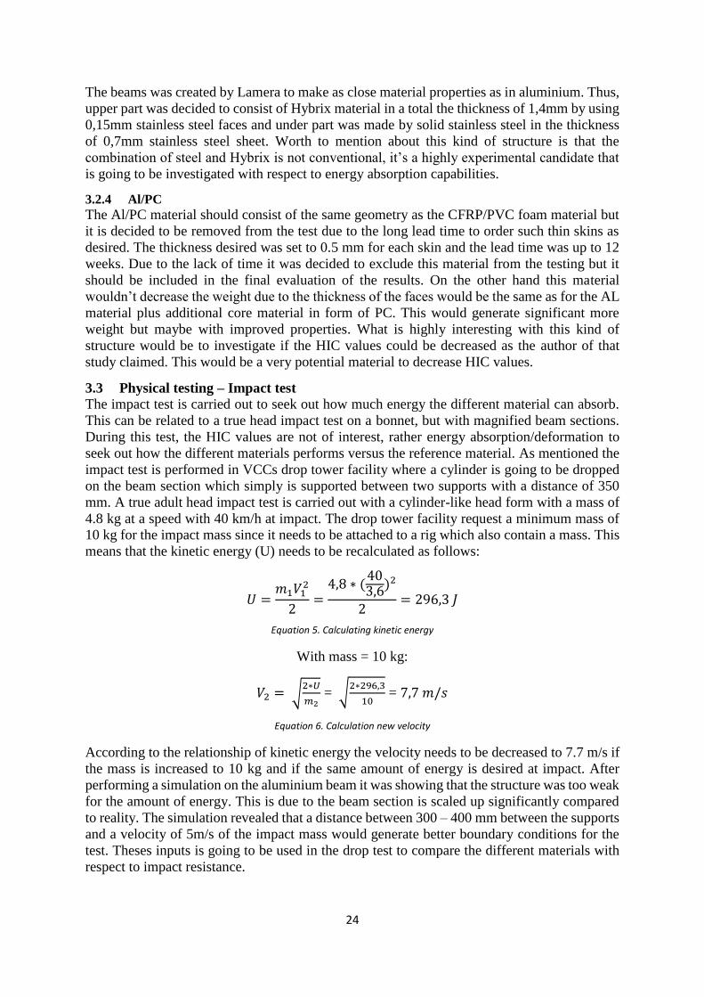
According to the relationship of kinetic energy the velocity needs to be decreased to 7.7 m/s if
the mass is increased to 10 kg and if the same amount of energy is desired at impact. After
performing a simulation on the aluminium beam it was showing that the structure was too weak
for the amount of energy. This is due to the beam section is scaled up significantly compared
to reality. The simulation revealed that a distance between 300 – 400 mm between the supports
and a velocity of 5m/s of the impact mass would generate better boundary conditions for the
test. Theses inputs is going to be used in the drop test to compare the different materials with
respect to impact resistance.
25
3.3.1 Bending test The bending test is represented in the laboratory of “Material centrum” at VCC. The bending
characteristic is a static three point bending test. The outcome of this test is to seek out the
bending stiffness of materials. The different materials subjected to this test has the geometry
of rectangular body. Since there is different materials, a dimension ratio is used among them.
The dimension of the candidate materials were calculated by using Volvo standard, STD 1024,
2511 and general standards ASTM C 393 – 00 and ASTM D 6252. The length of samples were
increased 20% more due to the material will slip on the span during bending.
The aluminium material consist of an upper part and under part containing a thickness of
0,9mm and 1,1 mm respectively placed together to achieve the same total thickness as the
conventional bonnet. Since the aluminium material has a thickness of 2mm, length and width
of samples were calculated to 150mm and 50mm, respectively.
Since the total thickness of Hybrix samples was 2.1mm as it is mentioned section 3.4.3, same
dimensions were used as for the aluminium samples. This means that the length and width of
the Hybrix material was calculated to 150mm and 50mm, respectively.
The CRFP/PVC foam sandwich material will have a different ratio due to that the thicker
thickness (12mm) will result in a total length of approximately 900 mm. This length is
considered to long for the bending test machine as the maximum length required is
approximately 500 mm. The length used for CRFP is 500 mm due to the requirement of the
bending machine. CFRP/PVC foam sandwich samples were produced with 500mm length,
50mm width and 12mm thickness.
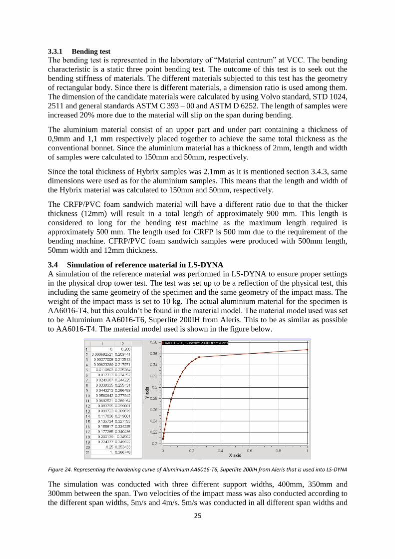
3.4 Simulation of reference material in LS-DYNA
A simulation of the reference material was performed in LS-DYNA to ensure proper settings
in the physical drop tower test. The test was set up to be a reflection of the physical test, this
including the same geometry of the specimen and the same geometry of the impact mass. The
weight of the impact mass is set to 10 kg. The actual aluminium material for the specimen is
AA6016-T4, but this couldn’t be found in the material model. The material model used was set
to be Aluminium AA6016-T6, Superlite 200IH from Aleris. This to be as similar as possible
to AA6016-T4. The material model used is shown in the figure below.
Figure 24. Representing the hardening curve of Aluminium AA6016-T6, Superlite 200IH from Aleris that is used into LS-DYNA
The simulation was conducted with three different support widths, 400mm, 350mm and
300mm between the span. Two velocities of the impact mass was also conducted according to
the different span widths, 5m/s and 4m/s. 5m/s was conducted in all different span widths and
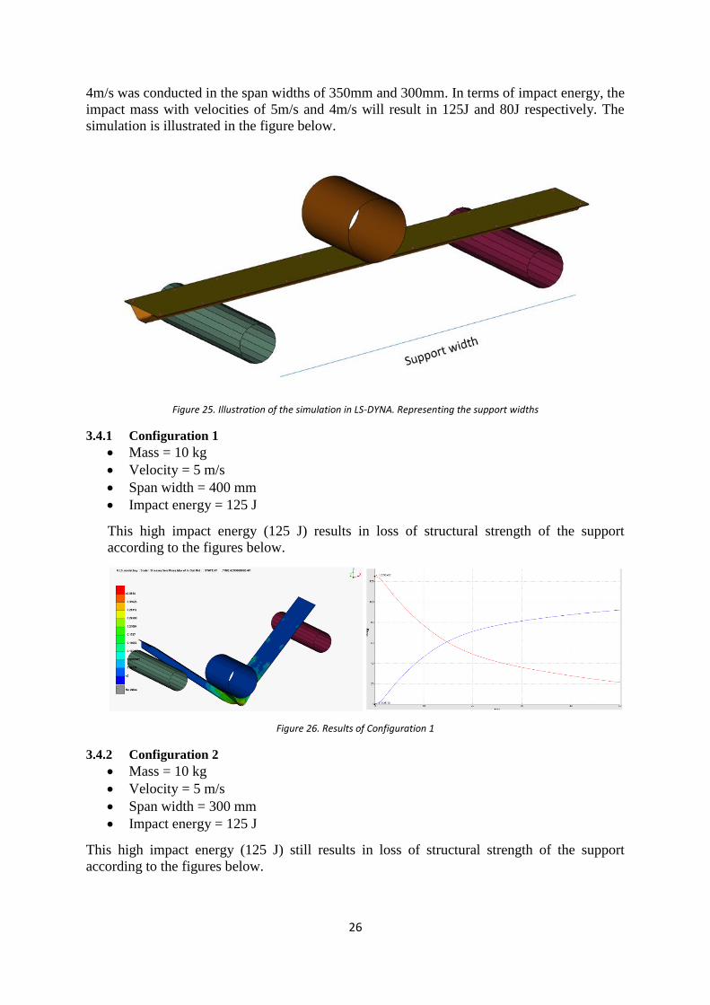
26
4m/s was conducted in the span widths of 350mm and 300mm. In terms of impact energy, the
impact mass with velocities of 5m/s and 4m/s will result in 125J and 80J respectively. The
simulation is illustrated in the figure below.
Figure 25. Illustration of the simulation in LS-DYNA. Representing the support widths
3.4.1 Configuration 1
Mass = 10 kg
Velocity = 5 m/s
Span width = 400 mm
Impact energy = 125 J
This high impact energy (125 J) results in loss of structural strength of the support
according to the figures below.
Figure 26. Results of Configuration 1
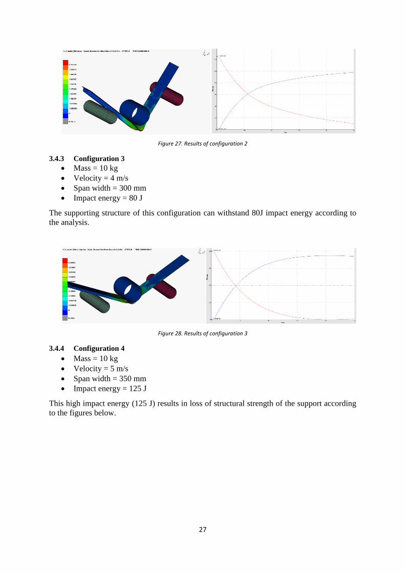
3.4.2 Configuration 2
Mass = 10 kg
Velocity = 5 m/s
Span width = 300 mm
Impact energy = 125 J
This high impact energy (125 J) still results in loss of structural strength of the support
according to the figures below.
27
Figure 27. Results of configuration 2
3.4.3 Configuration 3
Mass = 10 kg
Velocity = 4 m/s
Span width = 300 mm
Impact energy = 80 J
The supporting structure of this configuration can withstand 80J impact energy according to
the analysis.
Figure 28. Results of configuration 3
3.4.4 Configuration 4
Mass = 10 kg
Velocity = 5 m/s
Span width = 350 mm
Impact energy = 125 J
This high impact energy (125 J) results in loss of structural strength of the support according
to the figures below.
28
Figure 29. Results of configuration 4
3.4.5 Configuration 5
Mass = 10 kg
Velocity = 4 m/s
Span width = 350 mm
Impact energy = 125 J
The supporting structure of this configuration can withstand 80J impact energy according
to the analysis.
Figure 30. Results of configuration 5
3.4.6 Summary
According to these five configurations it is decided to exclude configuration 1 due to its too
much impact energy with respect to the span width of this test. The structure is simply too weak.
What can be determined throughout the other configurations is that the structure is still too
weak for the impact velocity of 5 m/s but it’s possible to measure force/deformation, how much
energy the structure actually is “eating up” (absorbing). In configuration 3 and 5 the structure
actually manages to absorb all energy (80 J) to not fail. This would be a proper result for the
aluminium structure, but since the physical testing is going to be compared with other materials
it is needed to take into consideration that the material consisting of CFRP/PVC might be much
stiffer and more energy absorbing than the reference material. Therefore it would be interesting
to test in the physical test 5 m/s and 4 m/s for a span width of 350 mm due to for 5 m/s the
structure is failing meanwhile for 4 m/s its resisting. According to this conclusion it’s decided
to use a configuration in the physical drop tower facility as follows:

29
Mass = 10 kg
Velocity = 5 m/s and 4 m/s
Span width = 350 mm
Impact energy = 125 J
This configuration would give a proper comparison among the different materials.
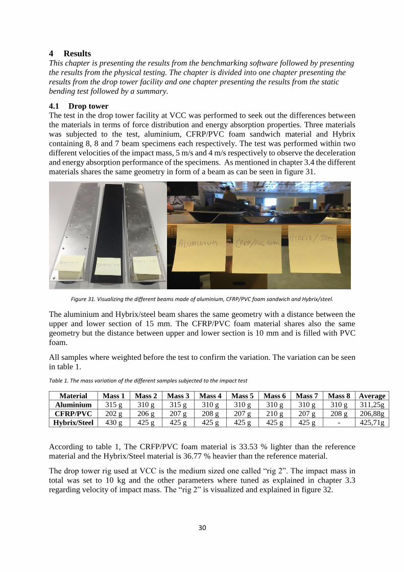
30
4 Results This chapter is presenting the results from the benchmarking software followed by presenting
the results from the physical testing. The chapter is divided into one chapter presenting the
results from the drop tower facility and one chapter presenting the results from the static
bending test followed by a summary.
4.1 Drop tower
The test in the drop tower facility at VCC was performed to seek out the differences between
the materials in terms of force distribution and energy absorption properties. Three materials
was subjected to the test, aluminium, CFRP/PVC foam sandwich material and Hybrix
containing 8, 8 and 7 beam specimens each respectively. The test was performed within two
different velocities of the impact mass, 5 m/s and 4 m/s respectively to observe the deceleration
and energy absorption performance of the specimens. As mentioned in chapter 3.4 the different
materials shares the same geometry in form of a beam as can be seen in figure 31.
Figure 31. Visualizing the different beams made of aluminium, CFRP/PVC foam sandwich and Hybrix/steel.
The aluminium and Hybrix/steel beam shares the same geometry with a distance between the
upper and lower section of 15 mm. The CFRP/PVC foam material shares also the same
geometry but the distance between upper and lower section is 10 mm and is filled with PVC
foam.
All samples where weighted before the test to confirm the variation. The variation can be seen
in table 1.
Table 1. The mass variation of the different samples subjected to the impact test
Material Mass 1 Mass 2 Mass 3 Mass 4 Mass 5 Mass 6 Mass 7 Mass 8 Average
Aluminium 315 g 310 g 315 g 310 g 310 g 310 g 310 g 310 g 311,25g
CFRP/PVC 202 g 206 g 207 g 208 g 207 g 210 g 207 g 208 g 206,88g
Hybrix/Steel 430 g 425 g 425 g 425 g 425 g 425 g 425 g - 425,71g
According to table 1, The CRFP/PVC foam material is 33.53 % lighter than the reference
material and the Hybrix/Steel material is 36.77 % heavier than the reference material.
The drop tower rig used at VCC is the medium sized one called “rig 2”. The impact mass in
total was set to 10 kg and the other parameters where tuned as explained in chapter 3.3
regarding velocity of impact mass. The “rig 2” is visualized and explained in figure 32.
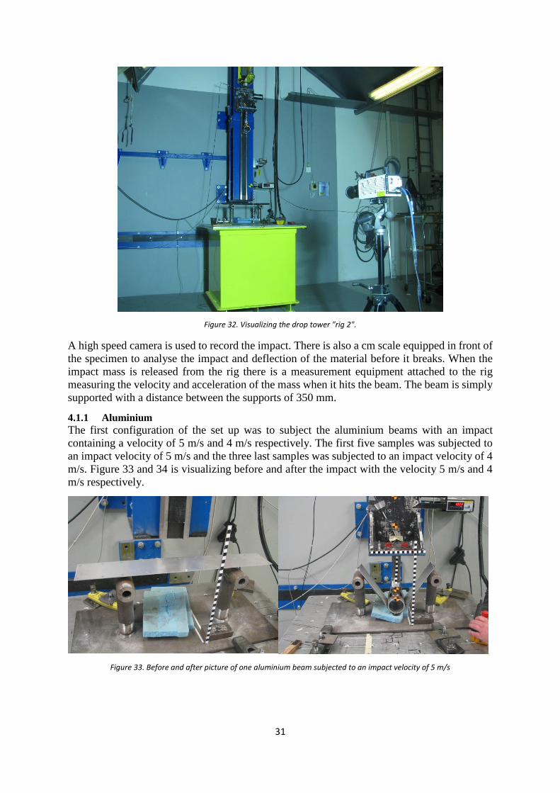
31
Figure 32. Visualizing the drop tower "rig 2".
A high speed camera is used to record the impact. There is also a cm scale equipped in front of
the specimen to analyse the impact and deflection of the material before it breaks. When the
impact mass is released from the rig there is a measurement equipment attached to the rig
measuring the velocity and acceleration of the mass when it hits the beam. The beam is simply
supported with a distance between the supports of 350 mm.
4.1.1 Aluminium
The first configuration of the set up was to subject the aluminium beams with an impact
containing a velocity of 5 m/s and 4 m/s respectively. The first five samples was subjected to
an impact velocity of 5 m/s and the three last samples was subjected to an impact velocity of 4
m/s. Figure 33 and 34 is visualizing before and after the impact with the velocity 5 m/s and 4
m/s respectively.
Figure 33. Before and after picture of one aluminium beam subjected to an impact velocity of 5 m/s
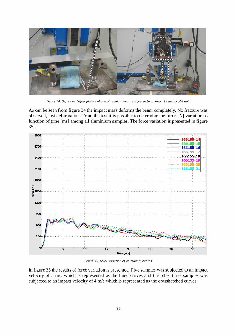
32
Figure 34. Before and after picture of one aluminium beam subjected to an impact velocity of 4 m/s
As can be seen from figure 34 the impact mass deforms the beam completely. No fracture was
observed, just deformation. From the test it is possible to determine the force [N] variation as
function of time [ms] among all aluminium samples. The force variation is presented in figure
35.
Figure 35. Force variation of aluminium beams
In figure 35 the results of force variation is presented. Five samples was subjected to an impact
velocity of 5 m/s which is represented as the lined curves and the other three samples was
subjected to an impact velocity of 4 m/s which is represented as the crosshatched curves.
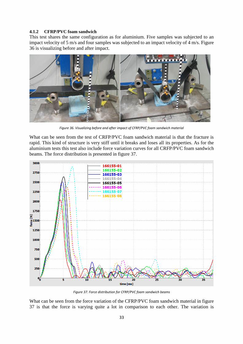
33
4.1.2 CFRP/PVC foam sandwich
This test shares the same configuration as for aluminium. Five samples was subjected to an
impact velocity of 5 m/s and four samples was subjected to an impact velocity of 4 m/s. Figure
36 is visualizing before and after impact.
Figure 36. Visualizing before and after impact of CFRP/PVC foam sandwich material
What can be seen from the test of CRFP/PVC foam sandwich material is that the fracture is
rapid. This kind of structure is very stiff until it breaks and loses all its properties. As for the
aluminium tests this test also include force variation curves for all CRFP/PVC foam sandwich
beams. The force distribution is presented in figure 37.
Figure 37. Force distribution for CFRP/PVC foam sandwich beams
What can be seen from the force variation of the CFRP/PVC foam sandwich material in figure
37 is that the force is varying quite a lot in comparison to each other. The variation is
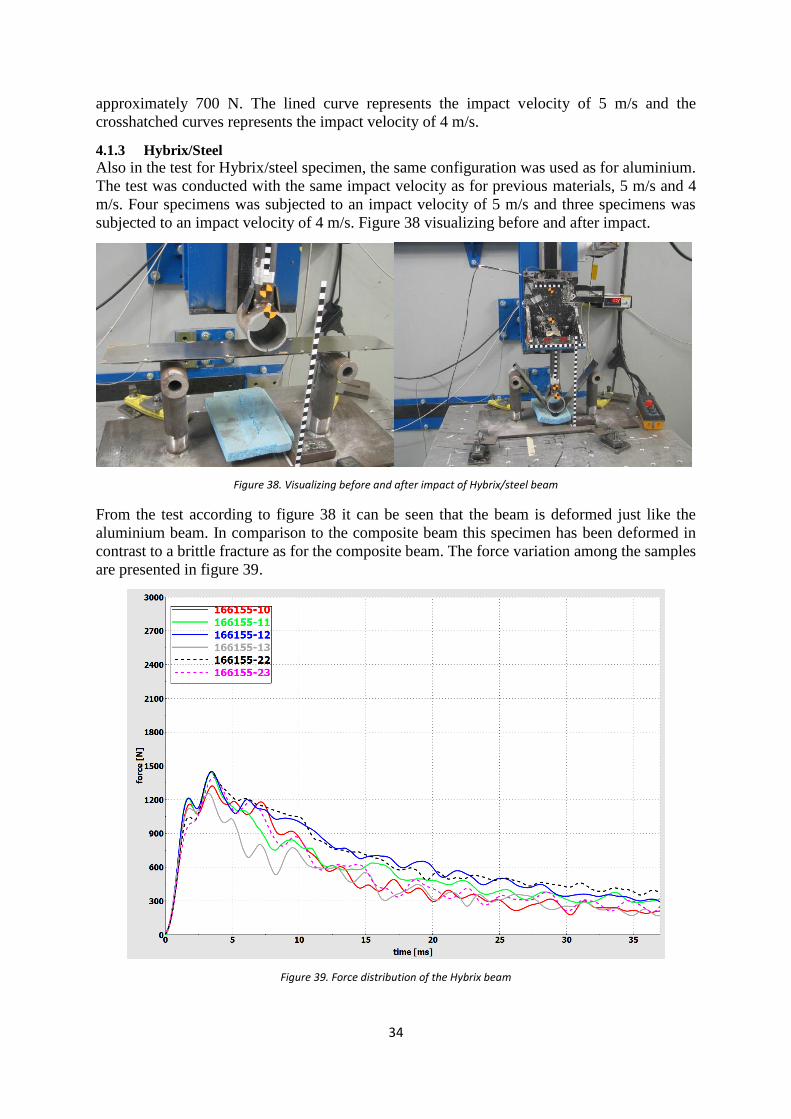
34
approximately 700 N. The lined curve represents the impact velocity of 5 m/s and the
crosshatched curves represents the impact velocity of 4 m/s.
4.1.3 Hybrix/Steel
Also in the test for Hybrix/steel specimen, the same configuration was used as for aluminium.
The test was conducted with the same impact velocity as for previous materials, 5 m/s and 4
m/s. Four specimens was subjected to an impact velocity of 5 m/s and three specimens was
subjected to an impact velocity of 4 m/s. Figure 38 visualizing before and after impact.
Figure 38. Visualizing before and after impact of Hybrix/steel beam
From the test according to figure 38 it can be seen that the beam is deformed just like the
aluminium beam. In comparison to the composite beam this specimen has been deformed in
contrast to a brittle fracture as for the composite beam. The force variation among the samples
are presented in figure 39.
Figure 39. Force distribution of the Hybrix beam
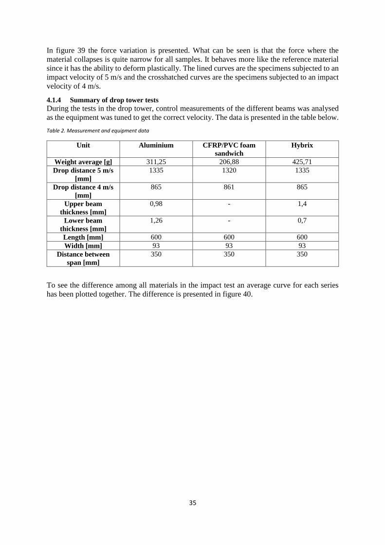
35
In figure 39 the force variation is presented. What can be seen is that the force where the
material collapses is quite narrow for all samples. It behaves more like the reference material
since it has the ability to deform plastically. The lined curves are the specimens subjected to an
impact velocity of 5 m/s and the crosshatched curves are the specimens subjected to an impact
velocity of 4 m/s.
4.1.4 Summary of drop tower tests
During the tests in the drop tower, control measurements of the different beams was analysed
as the equipment was tuned to get the correct velocity. The data is presented in the table below.
Table 2. Measurement and equipment data
Unit Aluminium CFRP/PVC foam
sandwich
Hybrix
Weight average [g] 311,25 206,88 425,71
Drop distance 5 m/s
[mm]
1335 1320 1335
Drop distance 4 m/s
[mm]
865 861 865
Upper beam
thickness [mm]
0,98 - 1,4
Lower beam
thickness [mm]
1,26 - 0,7
Length [mm] 600 600 600
Width [mm] 93 93 93
Distance between
span [mm]
350 350 350
To see the difference among all materials in the impact test an average curve for each series
has been plotted together. The difference is presented in figure 40.
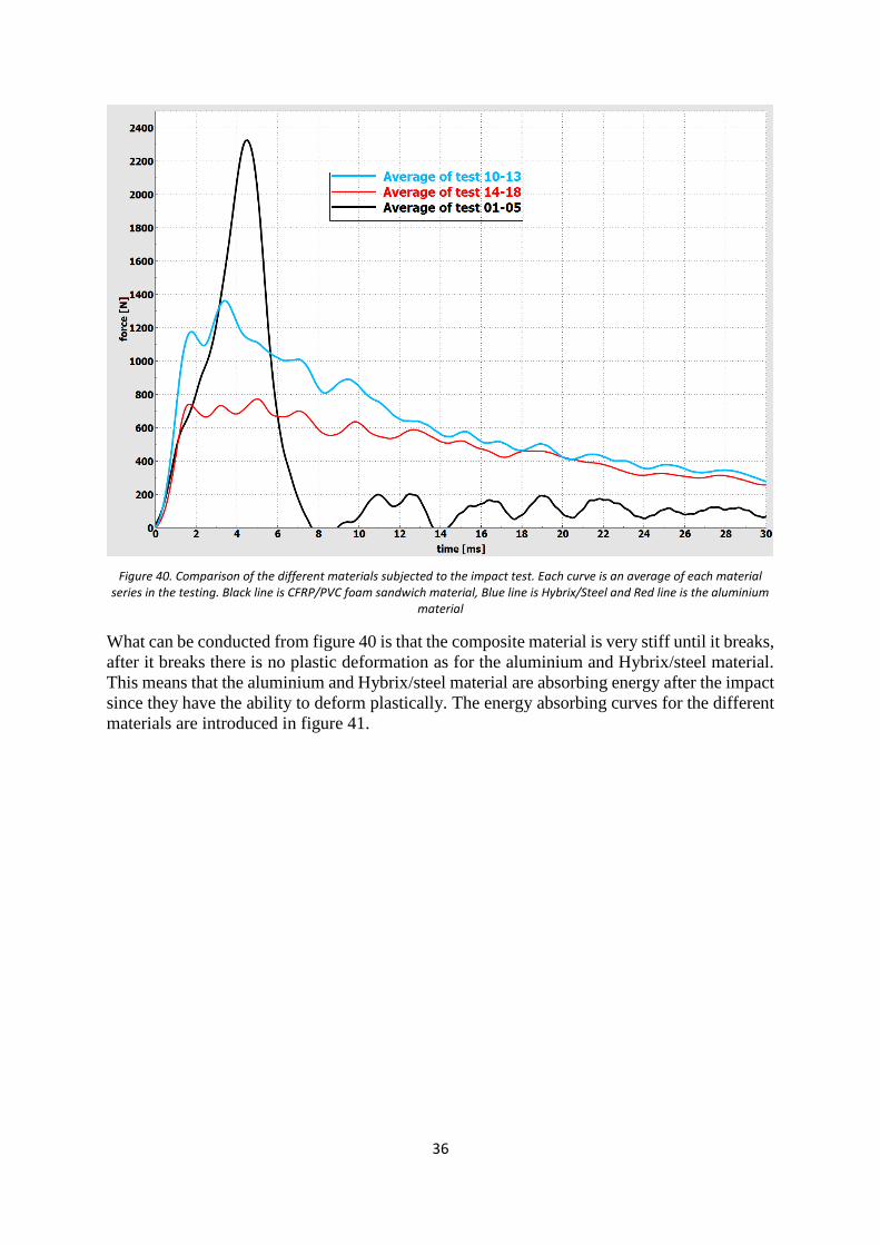
36
Figure 40. Comparison of the different materials subjected to the impact test. Each curve is an average of each material series in the testing. Black line is CFRP/PVC foam sandwich material, Blue line is Hybrix/Steel and Red line is the aluminium
material
What can be conducted from figure 40 is that the composite material is very stiff until it breaks,
after it breaks there is no plastic deformation as for the aluminium and Hybrix/steel material.
This means that the aluminium and Hybrix/steel material are absorbing energy after the impact
since they have the ability to deform plastically. The energy absorbing curves for the different
materials are introduced in figure 41.
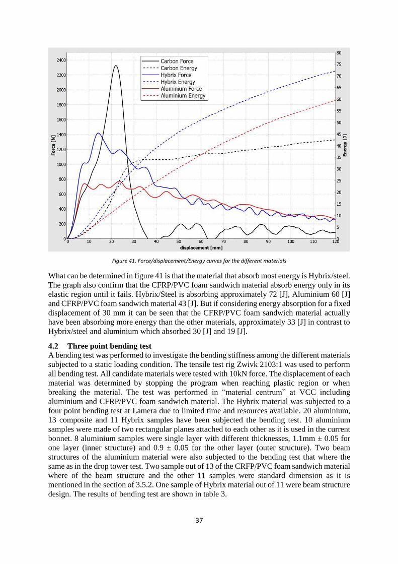
37
Figure 41. Force/displacement/Energy curves for the different materials
What can be determined in figure 41 is that the material that absorb most energy is Hybrix/steel.
The graph also confirm that the CFRP/PVC foam sandwich material absorb energy only in its
elastic region until it fails. Hybrix/Steel is absorbing approximately 72 [J], Aluminium 60 [J]
and CFRP/PVC foam sandwich material 43 [J]. But if considering energy absorption for a fixed
displacement of 30 mm it can be seen that the CFRP/PVC foam sandwich material actually
have been absorbing more energy than the other materials, approximately 33 [J] in contrast to
Hybrix/steel and aluminium which absorbed 30 [J] and 19 [J].
4.2 Three point bending test
A bending test was performed to investigate the bending stiffness among the different materials
subjected to a static loading condition. The tensile test rig Zwivk 2103:1 was used to perform
all bending test. All candidate materials were tested with 10kN force. The displacement of each
material was determined by stopping the program when reaching plastic region or when
breaking the material. The test was performed in “material centrum” at VCC including
aluminium and CFRP/PVC foam sandwich material. The Hybrix material was subjected to a
four point bending test at Lamera due to limited time and resources available. 20 aluminium,
13 composite and 11 Hybrix samples have been subjected the bending test. 10 aluminium
samples were made of two rectangular planes attached to each other as it is used in the current
bonnet. 8 aluminium samples were single layer with different thicknesses, 1.1mm ± 0.05 for
one layer (inner structure) and 0.9 ± 0.05 for the other layer (outer structure). Two beam
structures of the aluminium material were also subjected to the bending test that where the
same as in the drop tower test. Two sample out of 13 of the CRFP/PVC foam sandwich material
where of the beam structure and the other 11 samples were standard dimension as it is
mentioned in the section of 3.5.2. One sample of Hybrix material out of 11 were beam structure
design. The results of bending test are shown in table 3.
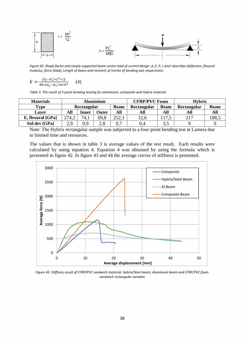
38
Figure 42. Shape factor and simply supported beam centre load of current design. Δ, E, P, L and I describes deflection, flexural modulus, force (load), Length of beam and moment of inertia of bending axis respectively.
𝐸 =(𝐹2−𝐹1)∗𝐿3∗12
48∗(𝑑2−𝑑1)∗𝑏∗ℎ3 (4)
Table 3. The result of 3 point bending testing for aluminium, composite and Hybrix material.
Materials Aluminium CFRP/PVC Foam Hybrix
Type Rectangular Beam Rectangular Beam Rectangular Beam
Layer All Inner Outer All All All All All
E, flexural [GPa] 274,2 74,1 69,8 252,1 12,6 117,5 217 188,5
Std dev [GPa] 2,9 0,9 2,8 0,7 0,4 3,5 9 0
Note: The Hybrix rectangular sample was subjected to a four-point bending test at Lamera due
to limited time and resources.
The values that is shown in table 3 is average values of the test result. Each results were
calculated by using equation 4. Equation 4 was obtained by using the formula which is
presented in figure 42. In figure 43 and 44 the average curves of stiffness is presented.
Figure 43. Stiffness result of CFRP/PVC sandwich material, Hybrix/Steel beam, Aluminium beam and CFRP/PVC foam sandwich rectangular samples
0
500
1000
1500
2000
2500
3000
0 10 20 30 40 50
Ave
rage
fo
rce
[N
]
Average displacement [mm]
Composite
Hybrix/Steel Beam
Al Beam
Composite Beam
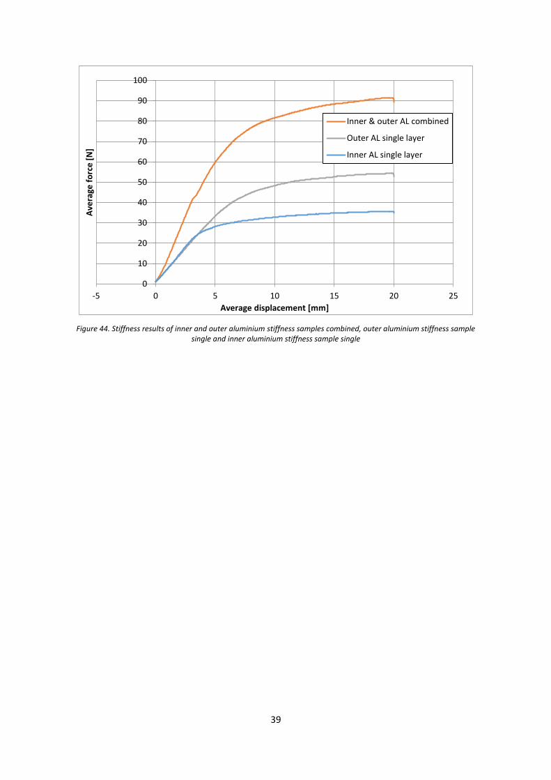
39
Figure 44. Stiffness results of inner and outer aluminium stiffness samples combined, outer aluminium stiffness sample single and inner aluminium stiffness sample single
0
10
20
30
40
50
60
70
80
90
100
-5 0 5 10 15 20 25
Ave
rage
fo
rce
[N
]
Average displacement [mm]
Inner & outer AL combined
Outer AL single layer
Inner AL single layer
40
5 Discussion
This project has been showing complexity in sense of finding appropriate materials that has
good energy absorbing properties at the same time as its reducing weight. The investigation
only treats a section of the bonnet where the key element was to reduce weight at the same time
as good properties are achieved. Within this scope there are several requirements included to
the bonnet e.g. flexural stiffness demands, A-surface demands and durability demands etc. This
study is limited to pedestrian safety and stiffness demands on the bonnet, which means that
more demands needs to be investigated to successfully change material in the bonnet.
The Aluminium material in this study was acting a reference material due to it’s the same
material as is used in the current bonnet. Regarding impact performance and stiffness of the
aluminium material it is the second best material in terms of energy absorption but the stiffest
material according to the bending test. Worth to mention about this kind of material is as
mentioned, it is used in the current bonnet. This means that this material passes all kind of
demands on the bonnet due to it has already been evaluated. To draw some kind of conclusions
among those three materials according to this study, the Hybrix/steel and CFRP/PVC foam
sandwich material should perform and show similar energy absorption and stiffness values as
for aluminium to ensure that they would be proper materials for pedestrian safety in form of
HIC values.
Regarding the results from the drop tower test at VCC among the three different beam materials,
it was resulting in Hybrix/steel material where showing the best energy absorption properties.
From the bending test it was shown that the Hybrix/steel beam was the second stiffest beam of
the three materials. According to the stiffness results this kind of structure passes the VCC
stiffness demands but unfortunately with no weight reduction. Regarding the weight, this kind
of structure was heavy in comparison to the aluminium beam, an increase of approximately
37 %. Since a steel console was used in the underpart of the beam this contribute with more
weight. More interesting to investigate would be if the complete beam was made of Hybrix
material to actually achieve a weight reduction.
The CRFP/PVC foam sandwich material was showing less good energy absorption properties
in comparison to the other materials. This can be explained due to composite material doesn’t
have the ability to deform plastically as for e.g. aluminium. What is happening within the
composite material when subjected to either impact or static bending test is that its eating
energy only in the elastic region until it breaks. This means that the current design of beam
elements in the bonnet cannot be used if composite material is going to be chosen. A complete
new design of the bonnet is desired if Volvo is going to use composite material. One other
option for composite material is to investigate further different types of composite/sandwich
material which performs in a similar way as for metals i.e. it can deform “plastically” or when
speaking of composites, achieve proper delamination. What’s also interesting to discuss
regarding this kind of material is what was shown in the result chapter, figure 39, for a fixed
displacement of 30 mm. At this displacement the CFRP/PVC foam sandwich material absorbed
most energy in contrast to the other materials. This can be interpreted as this kind of structure
has great potential in energy absorption in its elastic region. Another important parameter for
good properties when speaking of composites is the adhesion between each ply. After the
impact test of the composite beams it was noticed that some laminates was failed due to poor
adhesion. Worth to mention regarding composite materials in general is that they have got great
potential in fields of lightweight design. The CFRP/PVC foam sandwich beam where
approximately 34 % lighter than the aluminium beam.
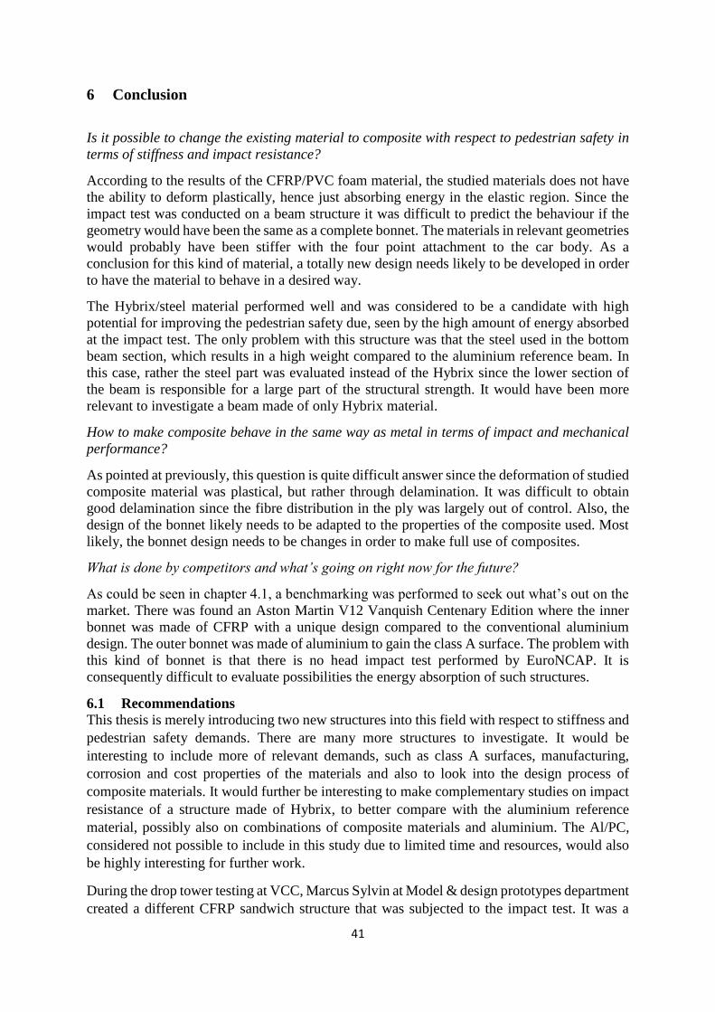
41
6 Conclusion
Is it possible to change the existing material to composite with respect to pedestrian safety in
terms of stiffness and impact resistance?
According to the results of the CFRP/PVC foam material, the studied materials does not have
the ability to deform plastically, hence just absorbing energy in the elastic region. Since the
impact test was conducted on a beam structure it was difficult to predict the behaviour if the
geometry would have been the same as a complete bonnet. The materials in relevant geometries
would probably have been stiffer with the four point attachment to the car body. As a
conclusion for this kind of material, a totally new design needs likely to be developed in order
to have the material to behave in a desired way.
The Hybrix/steel material performed well and was considered to be a candidate with high
potential for improving the pedestrian safety due, seen by the high amount of energy absorbed
at the impact test. The only problem with this structure was that the steel used in the bottom
beam section, which results in a high weight compared to the aluminium reference beam. In
this case, rather the steel part was evaluated instead of the Hybrix since the lower section of
the beam is responsible for a large part of the structural strength. It would have been more
relevant to investigate a beam made of only Hybrix material.
How to make composite behave in the same way as metal in terms of impact and mechanical
performance?
As pointed at previously, this question is quite difficult answer since the deformation of studied
composite material was plastical, but rather through delamination. It was difficult to obtain
good delamination since the fibre distribution in the ply was largely out of control. Also, the
design of the bonnet likely needs to be adapted to the properties of the composite used. Most
likely, the bonnet design needs to be changes in order to make full use of composites.
What is done by competitors and what’s going on right now for the future?
As could be seen in chapter 4.1, a benchmarking was performed to seek out what’s out on the
market. There was found an Aston Martin V12 Vanquish Centenary Edition where the inner
bonnet was made of CFRP with a unique design compared to the conventional aluminium
design. The outer bonnet was made of aluminium to gain the class A surface. The problem with
this kind of bonnet is that there is no head impact test performed by EuroNCAP. It is
consequently difficult to evaluate possibilities the energy absorption of such structures.
6.1 Recommendations
This thesis is merely introducing two new structures into this field with respect to stiffness and
pedestrian safety demands. There are many more structures to investigate. It would be
interesting to include more of relevant demands, such as class A surfaces, manufacturing,
corrosion and cost properties of the materials and also to look into the design process of
composite materials. It would further be interesting to make complementary studies on impact
resistance of a structure made of Hybrix, to better compare with the aluminium reference
material, possibly also on combinations of composite materials and aluminium. The Al/PC,
considered not possible to include in this study due to limited time and resources, would also
be highly interesting for further work.
During the drop tower testing at VCC, Marcus Sylvin at Model & design prototypes department
created a different CFRP sandwich structure that was subjected to the impact test. It was a
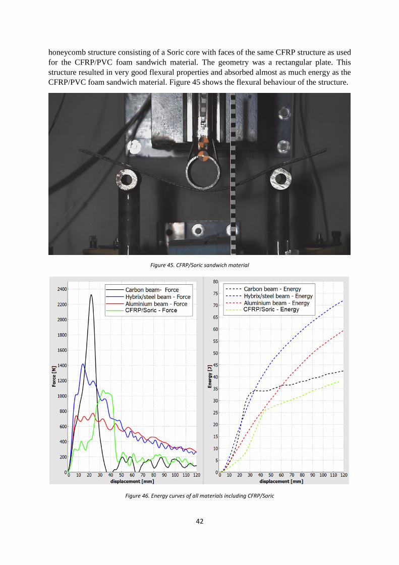
42
honeycomb structure consisting of a Soric core with faces of the same CFRP structure as used
for the CFRP/PVC foam sandwich material. The geometry was a rectangular plate. This
structure resulted in very good flexural properties and absorbed almost as much energy as the
CFRP/PVC foam sandwich material. Figure 45 shows the flexural behaviour of the structure.
Figure 45. CFRP/Soric sandwich material
Figure 46. Energy curves of all materials including CFRP/Soric

43
As shown in figure 46, the energy absorption of the CFRP/Soric structure was about the same
as for CFRP/PVC foam sandwich structure at a displacement of 110 mm, even though the
CFRP/Soric structure was quite different. The implication was that this material is highly
interesting for further investigations.
44
7 REFERENCES [1] A.Masoumi, Mohammad Hassan Shojaeefard, Amir Najibi, Comparison of steel,
aluminium and composite bonnet in term of pedestrian head impact, Safety Science. 1371(2011)
1371-1380
[2] Sunan Huang, Jijuang Yang, Optimization of a reversible bonnet for protecting a
pedestrian’s head during car collisions, Accicent Analysis and Prevention. (2010) 1136-1143.
[3] Azzam Ahmed, Li Wie, Inroduction CFRP as an alternative material for engine bonnet to
achieve better pedestrian safety using finite element modelling, Thin-Walled Structures. (2016),
97-108.
[4] Jia Zhaou, Feng Wang, Xinming Wan, Optimal design and experimental investigations of
aluminium sheet for lightweight of car bonnet, Aluminium two thousand world congress and
international conference on extrusion and benchmark ICEB 2015. 5029-5036.
[5] FMVSS No. 113, Bonnet Latch System. Japan Automobile Standards Internationalization
[6] Marcus Andersson, Petter Liedberg, Crash behaviour of composite structures, A CAE
benchmarking study, Master’s thesis in Applied Mechanics. Göteborg, Sweden 2014. ISSN
1652-8557
[7] R.F. Gibson, Principles of Composite Materials Mechanics, McGraw-Hill, 1994.
[8] G.L. Farley, “Energy Absorption of Composite Materials,” Journal of Composite
Materials 17 (1983), 267-279.
[9] H. Hamada, J.C Coppola, D. Hull, Z. Maekawa and H. Sato, “Comparison of Energy
Absorption of Carbon / Epoxy and Carbon / PEEK Composite Tubes,” Composites 23, no.
4 (1992), 245-252.
[10] S. Ramkrishna, H. Hamada and Z. Maekawa, “Energy Absorption Behavior of
Carbon-Reinforced Thermoplastic Composite Tubes,” Journal of Thermoplastic
Composite Materials 8 (1995), 323-344.
[11] D. Hull, “A Unified Approach to Progressive Crushing of Fiber-Reinforced Composite
Tubes,” Composite Science and Technology 40 (1991), 377-421.
[12] D. Hull, “Axial Crushing of Fibre Reinforced Composite Tubes,” Structural
Crashworthiness (1983), N. Jones and T. Weirzbicki (eds), 118-135
[13] Marc A. Courteau,” Investigating the Crashworthiness Characteristic of Carbon
Fibre/Epoxy Tubes”
[14] H. Hamada and S. Ramakrishna, “Effect of Fiber Orientation of the Energy Absorption
Capability of Carbon Fiber / PEEK Composite Tubes,” Journal of Composite Materials 30,
no. 8 (1996), 947-963.
[15] S. Ramakrishna and D. Hull, “Energy Absorption Capability of Epoxy Composite
Tubes with Knitted Carbon Fibre Fabric Reinforcement,” Composites Science and
Technology 49 (1993), 349-356.
[16] T. D. Jagannatha and G. Harish, “Mechanical Properties of Carbon/Glass Fibre
Reinforced Epoxy Hybrid Polymer Composite” International Journal of Mechanical
Engineering and Robotics Research, Vol. 4 No.2 April 2015.
[17] T-L Teng, C-C Liang, C-J Shih, M-T Nguyen, 2013. Design of car bonnet of sandwich
structures for pedestrian safety. International Journal of Vehicle Design, Vol. 63, 185-198.
[18] Lamera. 2013. Hybrix™ - products & technology. [ONLINE] Available at:
http://www.lamera.se/eng/index.php?option=com_content&task=view&id=13&Itemid=30.
[Accessed 15 April 2016].
[19] Axel S. Herrmann, Pierre C. Zahlen and Ichwan Zuardy, “Sandwich Structures
Technology in Commercial Aviation” Present Applications and Future Trends, 2015
[20] A.M. Pimentel, J.L. Alves, N.M. Merendeiro and D. Oliveira, “Experimental
Characterization of A Micro-sandwich Sheet”, Journal of Materials Processing Technology,
2015
45
[21] Ahad Torkestani, Mojtaba Sadighi, Reza Hedayati, “Effect of Material Type, Stacking
Sequence and Impact Location on the Pedestrian Head Injury in Collision”, Thin Walled
Structure 130-139, 2015
[22] Y.Bahei-El-Din, M. Shazly, S. Salem, “Impact resistance of sandwich plates”, Centre of
advanced materials, 2016
[23] Ashby, M.F. and Cebon, D. Case Studies in Materials Selection, Granta Design,
Trumpington. (1995)
[24] Ashby, M.F. Materials Selection in Mechanical Design, 2nd edn, Butterworth-Heinemann,
Oxford, (1999)
[25] Sandwich Structures - Altair Enlighten. 2016. Sandwich Structures - Altair Enlighten.
[ONLINE] Available at: http://altairenlighten.com/2012/07/sandwich-structures/. [Accessed 19
April 2016].
[26] Achilles Petras, “Design of Sandwich Structures”, Robinson College, Cambridge,
December 1998
[27] Starlinger Alois, “Sandwich Structures”, Stadler Rail Group, 2016. [ONLINE] Available
at: https://www1.ethz.ch/structures/education/master/ mechanics/Handouts/
Lecture_ETH_Sandwich_2013.pdf. [Accessed 26 April 2016]
[28] EuroNCAP – Pedestrian safety results of Renault Twingo, BMW i3 and Volvo XC90.
[ONLINE] Available at: http://www.euroncap.com/en/ratings-rewards/latest-safety-
ratings/#?selectedMake=0&selectedMakeName=Select a
make&selectedModel=0&includeFullSafetyPackage=true&includeStandardSafetyPackage=tr
ue&selectedModelName=All&selectedProtocols=24370,1472&selectedClasses=1202,1199,1
201,1196,1205,1203,1198,1179,1197,1204,1180&allClasses=true&allProtocols=false&allDri
verAssistanceTechnologies=false&selectedDriverAssistanceTechnologies=. [Accessed 29
April 2016]