Embed Size (px)
Citation preview

Guide to Using
GW3D
Version 1
by Environmental Simulations, Inc.

Copyright 2005 Environmental Simulations, Inc. All Rights Reserved. Microsoft is a registered trademark and Windows is a trademark of Microsoft. This manual was produced using Doc-To-Help® , by ComponentOne LLC ESI Programming by: Douglas B. Rumbaugh James O. Rumbaugh
esi EnvironmentalSimulationsInc.
Environmental Simulations, Inc.
P.O. Box 156 300 Mountain Top Rd Reinholds, PA 17569
tel. (610) 670-3400 fax. (610) 670-9239
www.groundwatermodels.com

Guide to Using GW3D Contents • iii
Contents
Introduction 1 What is GW3D? ........................................................................................................................................1 Package Contents and Installation.........................................................................................................1
What Comes with GW3D? .....................................................................................................1 Installing GW3D.......................................................................................................................1 Uninstalling GW3D .................................................................................................................2
Licensing....................................................................................................................................................2 Technical Support & Updates ................................................................................................................3
Getting Started with GW3D 4 Introduction...............................................................................................................................................4 Launching GW3D from Groundwater Vistas......................................................................................4 Zoom, Rotate, and Pan ............................................................................................................................7 Adding Features to the Image ................................................................................................................7 Display Options......................................................................................................................................10 Saving the Image ....................................................................................................................................10 Animation ................................................................................................................................................10
Tutorial 13
Introduction.............................................................................................................................................13 Running the Example Model................................................................................................................13 Launching GW3D ..................................................................................................................................15 Showing Isosurfaces ..............................................................................................................................17 Solid Representation of the Plume ......................................................................................................20 Working with Particle Traces ...............................................................................................................22
Image Options 26 Introduction.............................................................................................................................................26 Data...........................................................................................................................................................26 Isosurfaces ...............................................................................................................................................27 Solid ..........................................................................................................................................................28 Subgrid .....................................................................................................................................................29 Map...........................................................................................................................................................30 Lighting....................................................................................................................................................31 Surface......................................................................................................................................................32 Crop ..........................................................................................................................................................33 Shell ..........................................................................................................................................................34 Bar.............................................................................................................................................................35 Vector .......................................................................................................................................................35 Pathlines ...................................................................................................................................................36
Command Reference 38

iv • Contents Guide to Using GW3D
File Menu.................................................................................................................................................38 New...........................................................................................................................................38 Open..........................................................................................................................................38 Close.........................................................................................................................................38 Save/Save As...........................................................................................................................38 Print, Print Preview, Print Setup..........................................................................................38 Page Setup ...............................................................................................................................39 Map Overlay............................................................................................................................42 Import .......................................................................................................................................43 Export .......................................................................................................................................43 Export Animation ...................................................................................................................43 Send ..........................................................................................................................................44 Most Recently Used Files .....................................................................................................44 Exit ............................................................................................................................................44
Edit Menu ................................................................................................................................................44 Cut, Copy, Paste, Delete........................................................................................................44 Select All..................................................................................................................................45 Delete........................................................................................................................................45 Map Items ................................................................................................................................45 Site ............................................................................................................................................46 3D Manipulation.....................................................................................................................48 Reset, Save, Recall Viewpoint .............................................................................................48
View Menu ..............................................................................................................................................49 Standard Tools ........................................................................................................................49 GW3D Tools ...........................................................................................................................49 Status Bar.................................................................................................................................49 Toolbar Options ......................................................................................................................49 Automatic Refresh..................................................................................................................50 Refresh......................................................................................................................................50 Solid, Isosurface, None..........................................................................................................50 Flow Vectors ...........................................................................................................................50 Pathlines ...................................................................................................................................50 Model Features........................................................................................................................50 Map Overlays..........................................................................................................................50 View From Direction.............................................................................................................51 View From Next Direction ...................................................................................................51 Set Projection To ....................................................................................................................51 Next Time Step .......................................................................................................................51 Previous Time Step ................................................................................................................51
Add Menu ................................................................................................................................................51 Title ...........................................................................................................................................51 Parameter .................................................................................................................................52 Symbol .....................................................................................................................................53 Line ...........................................................................................................................................54 Frame ........................................................................................................................................55 Legend......................................................................................................................................57
Options Menu..........................................................................................................................................61 Parameters................................................................................................................................61 Map Overlays..........................................................................................................................61 Animation ................................................................................................................................62 Assume All Active Cells .......................................................................................................63
Window Menu.........................................................................................................................................64 Cascade.....................................................................................................................................64 Tile Horizontally.....................................................................................................................64 Tile Vertically .........................................................................................................................64 Arrange Icons..........................................................................................................................64

Guide to Using GW3D Contents • v
Split ...........................................................................................................................................64 Window 1, 2…........................................................................................................................64
Help Menu ...............................................................................................................................................64 Help Topics .............................................................................................................................64 What’s This?............................................................................................................................65 Tip of the Day .........................................................................................................................65 About GW3D ..........................................................................................................................65
References 68
Index 69


Guide to Using GW3D Introduction • 1
Introduction
What is GW3D?
GW3D is a program that works with Groundwater Vistas (GV) to view groundwater models in three dimensions. GW3D is designed to view the model domain, boundary conditions, aquifer properties, and model results. It is not designed to view general hydrogelogical data. GW3D is based on the USGS program called Model Viewer (Hsieh & Winston 2002), which has been extensively modified to interface with GV and also the make it easier to use. Many enhancements have also been added.
Both GW3D and Model Viewer are designed around the Visualization TookKit (VTK) developed by Will Schroeder, Ken Martin, and Bill Lorensen. VTK is an open source, freely available 3D graphics engine (Schroeder et al. 1997 and 2001). The company that maintains VTK is called KitWare and can be found on the web at http://public.kitware.com/VTK/.
Package Contents and Installation
What Comes with GW3D? GW3D comes with the three-dimensional viewing software and a program to create animations from bitmap files called bmp2avi. GW3D is sold as an add-on to Groundwater Vistas and requires you to have a valid Groundwater Vistas Version 4+ license.
You also receive full, context -sensitive help with GW3D and an electronic manual with tutorial that will help you get started. We also offer free technical support and updates are distributed through our Internet ftp site or from our web site (http://www.groundwatermodels.com).
Installing GW3D
GW3D is distributed on CD-ROM and uses an installation program that is similar to other Windows products. Normally, setup will start as soon as you put the CD-ROM

2 • Introduction Guide to Using GW3D
into your computer. If not, simply run setup.exe from the Program Manager File menu or the Run option on the Windows Start menu and follow the directions as the installation proceeds.
A dialog prompts for the hard disk drive letter and directory where the GW3D files will be stored. The default is c:\gw3d. Enter a new path for GW3D if you would like to place the files in a different directory. Click the OK button when you are done (you may also press the Enter key to accept the drive and directory). Select CANCEL at any time to terminate the installation process.
A dialog will now appear allowing you to name the Program Manager Group for the GW3D icon. The default name is GW3D. To change the group name, you may select from an existing group listed in the dialog or name a new one. Select OK to accept your choice.
Uninstalling GW3D You uninstall GW3D like any other Windows program. Double -click My Computer and then double-click the Control Panel. Double-click the Add/Remove Programs icon. Select GW3D from the list of programs and click the Add/Remove button on the dialog. Just follow the prompts from the uninstall wizard from there.
Licensing There are two licensing options with GW3D. The first option is to have a license for Groundwater Vistas Version 4 Enterprise Edition, which comes with GW3D. You then simply install GW3D on the same hard disk drive as the Groundwater Vistas directory and GW3D will run whenever Groundwater Vistas is capable of running (that is, you either have a security code for Groundwater Vistas or you have a hardware lock for Groundwater Vistas Enterprise Edition).
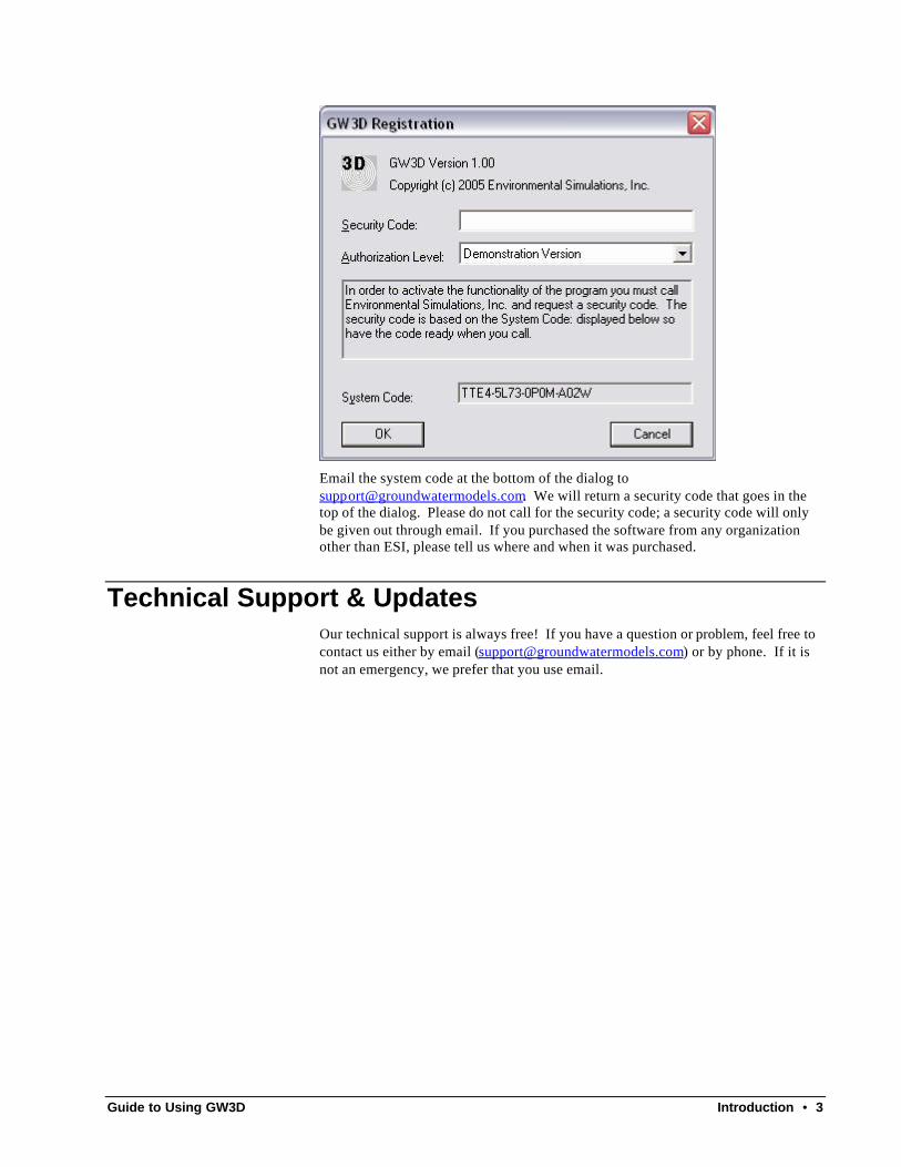
The second licensing option is to purchase GW3D to work with an existing copy of Groundwater Vistas (Standard or Advanced versions). In this case, you will then need a separate security code for GW3D. To obtain a security code, run GW3D, select Help/About GW3D and click the Register button. An example of the registration window is shown below.
Guide to Using GW3D Introduction • 3
Email the system code at the bottom of the dialog to [email protected]. We will return a security code that goes in the top of the dialog. Please do not call for the security code; a security code will only be given out through email. If you purchased the software from any organization other than ESI, please tell us where and when it was purchased.
Technical Support & Updates Our technical support is always free! If you have a question or problem, feel free to contact us either by email ([email protected]) or by phone. If it is not an emergency, we prefer that you use email.

4 • Getting Started with GW3D Guide to Using GW3D
Getting Started with GW3D
Introduction The first thing to consider when viewing a groundwater model in three dimensions is that the model should be three-dimensional! That should be patently obvious; however, even three dimensional models will not yield very pleasing results in 3D if there are only a few layers. In a lot of cases, models tend to have just a very few layers and in these cases, the three dimensional representation of such a model will not be very spectacular. Therefore, if you know that one of your ultimate uses of the model is to produce a cool animation or other 3D effect, you need to add more layers than you might have originally planned. This is especially true for contaminant transport analyses.
Launching GW3D from Groundwater Vistas GW3D is designed to work with Groundwater Vistas and to view groundwater models and model results in three dimensions. It is very easy to start using GW3D. Simply open your model in Groundwater Vistas and select 3D\Options from the main menu. This sets up the basic options before launching GW3D. The Options dialog is shown below:

Guide to Using GW3D Getting Started with GW3D • 5
The type of 3D view is either the default (which starts a new view of the model in GW3D with basic options) or “Existing GW3D File”. The latter is used when you already have a 3D view prepared in GW3D and just want to launch GW3D to view it again. The name of the GW3D file is then placed in the field labeled “GW3D File Name”. GW3D files use the extension “gw3”.
The Model Type is either MODFLOW or MT3D. Choose MODFLOW to view head and drawdown information or MT3D to view concentrations.
The path to the GW3D program should be set appropriately if you installed GW3D in the default directory. Otherwise, browse to find the file gw3d.exe.
GW3D will display the same base maps as your Groundwater Vistas model. Maps can either be draped over the top of layer 1 or on a flat plane. In either case, the distance between the map and the top of model layer 1 is also entered as the “gap” value. The final option on the dialog is the vertical exaggeration. These last three options on the bottom of the dialog can be changed after launching GW3D.
At the bottom of the dialog is a list of other data types that can be viewed in 3D. By default, GW3D will display head, drawdown, and pathlines for MODFLOW or concentrations for MT3D, and also positions of boundary conditions. Most other matrix data types in Vistas can also be displayed, including hydraulic conductivity, storage, etc.
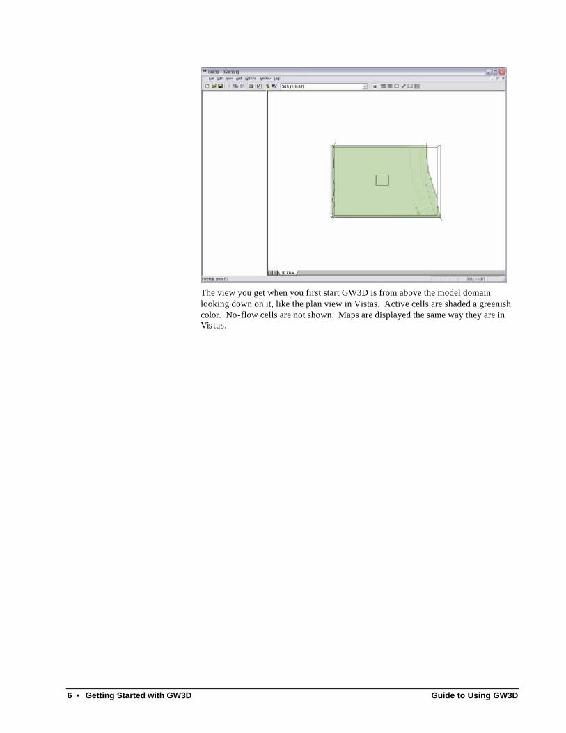
After selecting the options above, choose 3D/Launch GW3D. Your screen should then look like the one below.
6 • Getting Started with GW3D Guide to Using GW3D
The view you get when you first start GW3D is from above the model domain looking down on it, like the plan view in Vistas. Active cells are shaded a greenish color. No-flow cells are not shown. Maps are displayed the same way they are in Vis tas.

Guide to Using GW3D Getting Started with GW3D • 7
Zoom, Rotate, and Pan One of the first things you will want to do is change the view of the model by zooming in or out, rotating the image, and panning. The first step in changing the image is to click anywhere on the 3D image to make it active. Then click the 3D button on the toolbar or select Edit/3D Manipulation/Mouse Mode . Now you are free to manipulate the image using the following techniques:
• Zoom in: press and hold the right mouse button and move the cursor upward.
• Zoom out: press and hold the right mouse button and move the cursor downward.
• Rotate: press and hold the left mouse button and move the cursor in the direction of rotation.
• Rotate perpendicular to the screen: hold down the control key (CTRL), press and hold the left mouse button, and drag in the direction of rotation.
• Pan: hold down the shift key, press and hold the left mouse button, and drag the cursor in the direction of panning.
The operation that takes the most practice is rotating the image. The manner in which the image is rotated depends on not only the direction you drag the mouse but on where you click to start the rotation.
Adding Features to the Image GW3D can display the following types of information on the image:
• Solid representation of data in each cell:

8 • Getting Started with GW3D Guide to Using GW3D
• Isosurface representation of data in each cell:
• Velocity vectors:
Guide to Using GW3D Getting Started with GW3D • 9
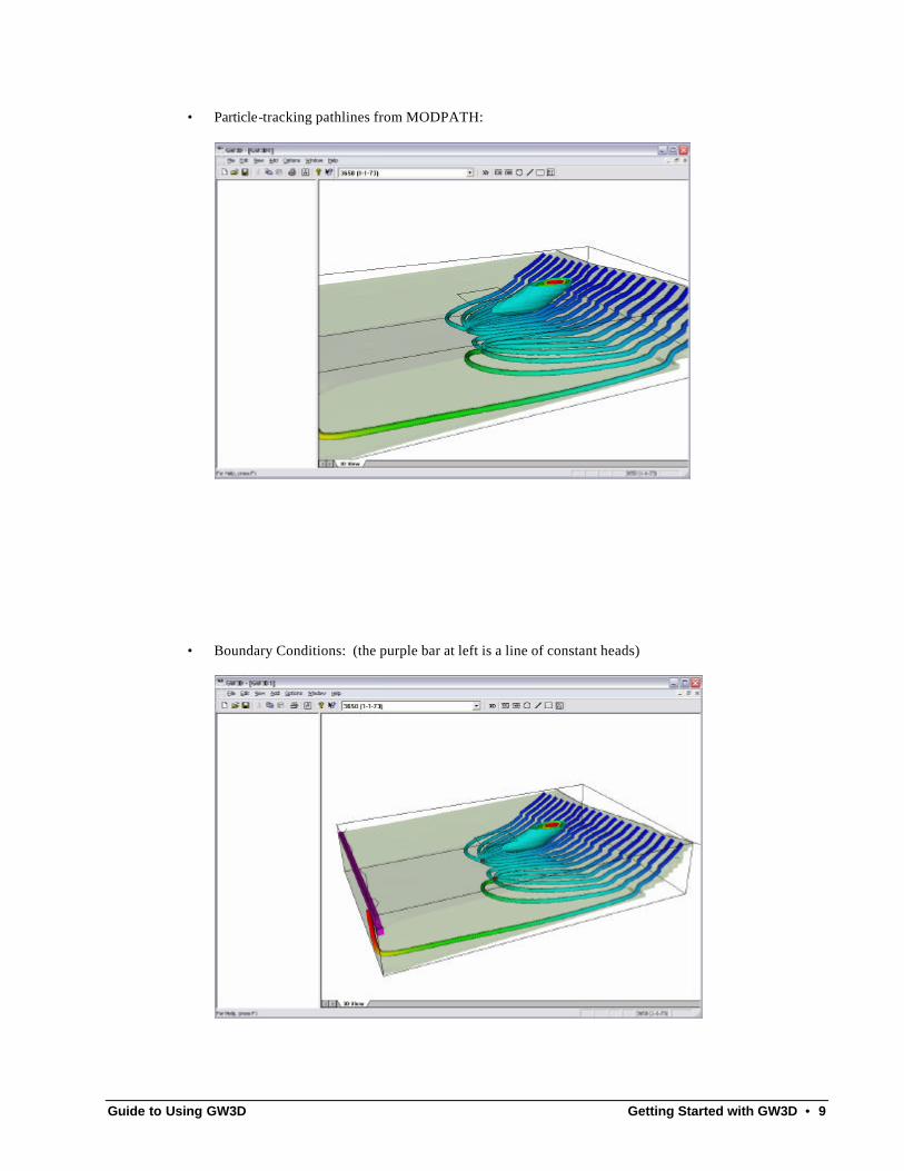
• Particle-tracking pathlines from MODPATH:
• Boundary Conditions: (the purple bar at left is a line of constant heads)

10 • Getting Started with GW3D Guide to Using GW3D
These image features are toggled on and off from the View menu. The option called Model Features primarily represents boundary conditions.
Display Options There are numerous options for how each of these model features is displayed. The
options are controlled by clicking the button on the toolbar or selecting Options/Parameters . A tab dialog is then displayed, as shown below:
Most of the selections on this dialog are fairly easy to figure out. For detailed information on each tab of this dialog, see the Image Options Chapter later in this manual.
Saving the Image When you have an image you like and want to be able to display it instantly in GW3D, simply select File/Save As and give it a name. The file will have a *.gw3 extension. You can then open this file in GW3D and it will be displayed using the same options as when you saved it. You may automatically launch GW3D from Groundwater Vistas and open an existing *.gw3 file as described in the first part of this chapter. You may als o double-click on the *.gw3 file in Windows Explorer to open GW3D and display the image.
Animation A common use of 3D visualization software is to create an animation of the model. There are two ways of doing this in GW3D. The first is to create and play an

Guide to Using GW3D Getting Started with GW3D • 11
animation on the screen within GW3D. This is accomplished using Options/Animation. Next, set up the options such as number of seconds to display each image. Finally click the Set button and the Run button to play the animation.
To make a permanent movie file that you can show at a later time, select File/Export Animation. Fill in similar options as for the animation technique described above. In addition, you specify a directory for the files and a root name for the image files. A series of images will be saved in the directory with names in sequence. For example, if the root name is test, then the firs image will be test001.bmp, etc.

12 • Getting Started with GW3D Guide to Using GW3D
A simple application called bmp2avi.exe is provided with GW3D than can put these files together into a movie. Check the option labeled “Create AVI Movie File” to automatically run bmp2avi. The use of this program outside of GW3D is documented in the file bmp2avi.htm. A typical command line would be:
bmp2avi –i test –o test –f 1
where “i” is the input name prefix, “o” is the output name (bmp2avi will attach a *.avi extension), and the number after “f” is the number of frames per second.

Guide to Using GW3D Tutorial • 13
Tutorial
Introduction The GW3D exercise, described below, introduces you to most of the important features of this software in a step-by-step example. You will be given very specific instructions to show how to use GW3D to view a model that is provided in Groundwater Vistas Version 4. In a graphical user interface such as Windows, it is difficult to tell you exactly what to do during each step because many of the steps involve using the mouse. This demonstration provides several snap-shots of the GW3D screens to show you what your screen should look like, however, in case you miss a step.
Running the Example Model Before using GW3D, we need to run the example model in Groundwater Vistas. Run Groundwater Vistas and open the file called c:\gw3d\examples\gw3d_example.gwv. If you installed GW3D in another directory then browse to find that directory. The model should look like the following:

14 • Tutorial Guide to Using GW3D
This model is essentially the Groundwater Vistas tutorial example with a much finer grid spacing and many more layers. As mentioned in the last chapter, you can only get good results with 3D visualization when you have lots of layers.
Now, run MODFLOW by clicking the calculator button on the toolbar. Answer “YES” to the first prompt to create data files and then “NO” to the next prompt about displaying the error file. After the model runs, import the results of the run. After MODFLOW runs, run MT3D. Select Model/Use MT3D and then click the calculator button. Select “YES” to create data files and then “CANCEL” to avoid seeing the error file. After the MT3D run is finished, import the results for transport step number , as shown below.

Guide to Using GW3D Tutorial • 15
Click OK and you should see a contaminant plume displayed like the one below:
Launching GW3D We will now view the contaminant plume in 3D using GW3D. Select 3D/Options and the following dialog is displayed:
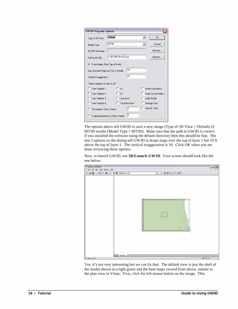
16 • Tutorial Guide to Using GW3D
The options above tell GW3D to start a new image (Type of 3D View = Default) of MT3D results (Model Type = MT3D). Make sure that the path to GW3D is correct. If you installed the software using the default directory then this should be fine. The last 3 options on the dialog tell GW3D to drape maps over the top of layer 1 but 10 ft above the top of layer 1. The vertical exaggeration is 10. Click OK when you are done reviewing these options.
Now, to launch GW3D, use 3D/Launch GW3D. Your screen should look like the one below:
Yes, it’s not very interesting but we can fix that. The default view is just the shell of the model shown in a light green and the base maps viewed from above, similar to the plan view in Vistas. First, click the left mouse button on the image. This
Guide to Using GW3D Tutorial • 17
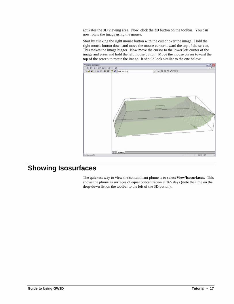
activates the 3D viewing area. Now, click the 3D button on the toolbar. You can now rotate the image using the mouse.
Start by clicking the right mouse button with the cursor over the image. Hold the right mouse button down and move the mouse cursor toward the top of the screen. This makes the image bigger. Now move the cursor to the lower left corner of the image and press and hold the left mouse button. Move the mouse cursor toward the top of the screen to rotate the image. It should look similar to the one below:
Showing Isosurfaces The quickest way to view the contaminant plume is to select View/Isosurfaces . This shows the plume as surfaces of equal concentration at 365 days (note the time on the drop-down list on the toolbar to the left of the 3D button).

18 • Tutorial Guide to Using GW3D
Change the time value from 365 to 3,650 by clicking on the drop down list of time values and scrolling to the bottom. The plume at 3,650 days should look like the one below:
GW3D just chooses some arbitrary values to contour in 3D. You can change the concentration levels to show by selecting Options/Parameters and clicking on the Isosurfaces tab. Click on the option to customize levels and enter the values of 1, 10, 50, 100, and 400 in the spreadsheet.

Guide to Using GW3D Tutorial • 19
Click OK or Apply and the plume should now look like the one below:
Sometimes it might be difficult to see the inside of the plume with isosurfaces. One way to see inside is to cut away part of the model area. Select Options/Parame ters and click on the Subgrid tab. Change the minimum j value from 0 to 34, click on the “Activate Subgrid” checkbox and click OK.

20 • Tutorial Guide to Using GW3D
Now the screen should look like the following:
Solid Representation of the Plume You can also view the plume as a colored solid block. Select View/Solid and the image should look like the following:

Guide to Using GW3D Tutorial • 21
Notice that the solid uses the same subgrid as you created for the isosurfaces. One common option for solids, especially when viewing concentrations, is to remove the very low concentration values. Select Options/Parameters and click on the Solids tab. Click on the option to Apply Thresholds and change the minimum level to 1.
Click OK or Apply and the image should look like the following:

22 • Tutorial Guide to Using GW3D
You should experiment with the “smooth”, “blocky”, and “banded” options for display of solids on the dialog above. The blocky display is best for viewing model input properties if they have been entered based on zones. Smooth is good for continuously varying properties. Each gives the image a different look.
Working with Particle Traces Go back into Groundwater Vistas and run MODPATH. Select Model/Use Modpath and click the calculator button on the toolbar. Import the particle traces into Vistas after you are done and your screen should look like the one below.
Guide to Using GW3D Tutorial • 23
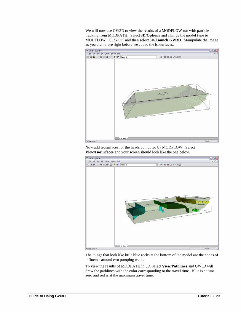
We will now use GW3D to view the results of a MODFLOW run with particle -tracking from MODPATH. Select 3D/Options and change the model type to MODFLOW. Click OK and then select 3D/Launch GW3D. Manipulate the image as you did before right before we added the isosurfaces.
Now add isosurfaces for the heads computed by MODFLOW. Select View/Isosurfaces and your screen should look like the one below.
The things that look like little blue rocks at the bottom of the model are the cones of influence around two pumping wells.
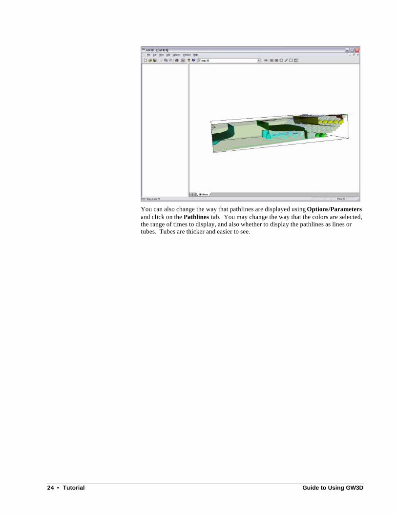
To view the results of MODPATH in 3D, select View/Pathlines and GW3D will draw the pathlines with the color corresponding to the travel time. Blue is at time zero and red is at the maximum travel time.
24 • Tutorial Guide to Using GW3D
You can also change the way that pathlines are displayed using Options/Parameters and click on the Pathlines tab. You may change the way that the colors are selected, the range of times to display, and also whether to display the pathlines as lines or tubes. Tubes are thicker and easier to see.
Guide to Using GW3D Tutorial • 25

26 • Image Options Guide to Using GW3D
Image Options
Introduction Options for display of the various 3D features are provided in GW3D on the
Options/Parameters menu or by clicking the button on the toolbar. A property sheet with numerous tabs is displayed as shown below. The following sections in this chapter document what each control represents.
Data The Data tab determines what data type is displayed when you choose isosurfaces or solids. Data types include head and drawdown for MODFLOW and concentration for MT3D. In addition, any of the data types listed at the bottom of the 3D Options dialog in Vistas are also contained on the drop-down list of data types. The latter can include hydraulic conductivity, storage, leakance, recharge, etc. For those data types that can be transient, such as head or concentration, there is also a time drop-down list which shows all available times saved by MODFLOW or MT3D in the binary output files.
At the bottom of the tab are the “Model Features” that can be displayed. These are generally boundary conditions defined in Vistas such as constant heads, wells, drains, etc. Click on the ones you want to display. You may also choose a color for each boundary types. The Up and Down buttons chance the order in wh ich boundary conditions are displayed.

Guide to Using GW3D Image Options • 27
Isosurfaces The Isosurfaces tab controls the contouring in three-dimensions. An isosurface is a three-dimensional contour. The “calculated Z range” shows the range in the data values for the data type to be displayed (see Data tab). The minimum level and maximum level fields allow you to only show isosurface contours within a certain range. The Number field is the number of isosurfaces displayed. If the Customize Levels check-box in not checked, then the isosurfaces are equally spaced between the min and max levels. On the other hand, if you check the box to customize levels, you then enter each isosurface level in the spreadsheet below.

28 • Image Options Guide to Using GW3D
The Scale section at the bottom of the Isosurface tab controls the exaggeration in all three dimensions. Normally the X and Y scales are 1.0. The Z scale is the degree of vertical exaggeration. A Z scale of 10 is good for many cases, but depends on the relative difference between the X and Z dimensions of the model.
Solid The Solid tab determines how solid color-flooded images are drawn in three dimensions. The “calculated Z range” shows the range in the data values for the data type to be displayed (see Data tab). The minimum level and maximum level fields allow you to only show the solid image within a certain range of data values if the Apply Thresholds check-box is checked.
There are three types of solid images that can be displayed. The default is smooth. In the smooth solid image, the data values are interpolated in three-dimensions. A blue color represents the lowest value and red represents the highest value and the remaining colors are graded smoothly between the two extremes. In the blocky image, the same colors are chosen; however, the colors are applied as a constant color with each grid cell. Thus, for properties that vary discretely (such as those defined in zones in Vistas), the blocky pattern is better than the smooth pattern. The banded pattern, a contour-like effect is produced where band represents a contour interval. The number of bands is also a user-defined parameter.

Guide to Using GW3D Image Options • 29
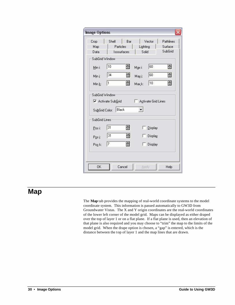
Subgrid The Subgrid tab allows you to only display a portion of the model domain. Any information outside the subgrid is not displayed. The “i” dimension is the same as X or the mo del columns. The “j” dimension is Y or rows and the “k” dimension is Z or layers. Note that j and k dimesions are backwards from the way that MODFLOW/MT3D number rows and layers. A value of k=1 is the bottom-most layer of the model and a value of j=1 is the southern-most row.
To use the subgrid, enter values for i, j, and k at the top and then check the box labeled “Activate SubGrid” in the center of the dialog.
30 • Image Options Guide to Using GW3D
Map The Map tab provides the mapping of real-world coordinate systems to the model coordinate system. This information is passed automatically to GW3D from Groundwater Vistas. The X and Y origin coordinates are the real-world coordinates of the lower left corner of the model grid. Maps can be displayed as either draped over the top of layer 1 or on a flat plane. If a flat plane is used, then an elevation of that plane is also required and you may choose to “trim” the map to the limits of the model grid. When the drape option is chosen, a “gap” is entered, which is the distance between the top of layer 1 and the map lines that are drawn.

Guide to Using GW3D Image Options • 31
Lighting The Lighting tab allows fine adjustment of how the graphic objects are illuminated. The default lighting is a “headlight” illuminating the graphic objects from the direction of the viewpoint. This setting is usually adequate for most cases. However, for fine adjustments, the headlight intensity may be decreased or completely turned off (under the “Lights” tab). In addition, you may turn on an “auxiliary light” for illumination from a direction specified by a vector whose x-y-z components may vary from -1 to 1. For example, if x=1, y=0, z=0, the auxiliary light will shine from the positive x axis towards the negative x axis.
32 • Image Options Guide to Using GW3D
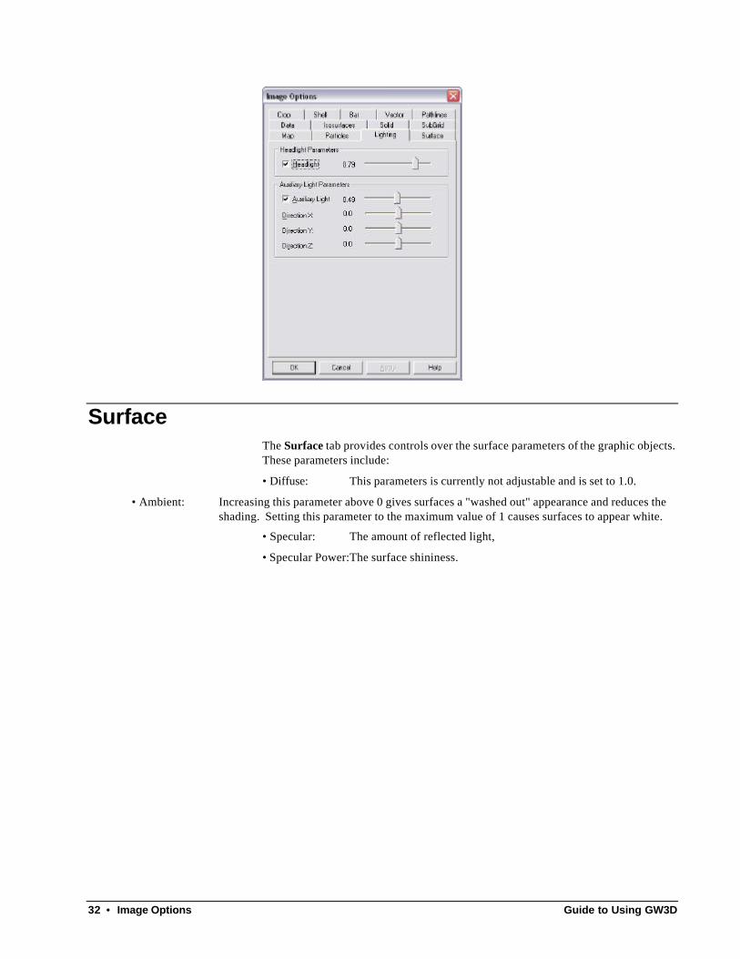
Surface The Surface tab provides controls over the surface parameters of the graphic objects. These parameters include:
• Diffuse: This parameters is currently not adjustable and is set to 1.0.
• Ambient: Increasing this parameter above 0 gives surfaces a "washed out" appearance and reduces the shading. Setting this parameter to the maximum value of 1 causes surfaces to appear white.
• Specular: The amount of reflected light,
• Specular Power:The surface shininess.

Guide to Using GW3D Image Options • 33
Crop The Crop tab controls cropping a solid or a set of isosurfaces. The cropping planes are defined by normalized coordinate along the x, y, and z edges of the bounding box (that is, they range from 0 to 1). These normalized coordinates are entered into the boxes under “Min” and “Max” (under the “Controls” tab). Clicking the up or down arrowheads increases or decreases the Max or Min value by the amount in the “Delta” box. Checking the “Max = Min” option sets the Max value equal to the Min value to display a two-dimensional slice. The “Options” tab provides the option to display the outer shell of the cropped-away solid or the cropped-away isosurfaces. The four sliders can be used to set the color and opacity of the cropped-away pieces. There is also a color button to make selection of color easier.

34 • Image Options Guide to Using GW3D
Shell The grid shell is a semi-transparent surface showing the outside of the active model grid. You may choose to turn off this shell and you may also add axis labels to show the X, Y, and/or Z axes. The color of the grid shell may also be changed, either with sliders to with a color button.

Guide to Using GW3D Image Options • 35
Bar A color bar may be displayed on the image to illustrate how the colors are mapped from blue to red. The color scales are controlled, along with an option for a logarithmic scaling. The parameters at the top of the dialog not only control how the bar is displayed but also how colors are mapped to the data for isosurfaces and solids.
Vector Velocity vectors may be displayed on the image. The vectors are short lines that originate at the center of a model cell and point in the direction of flow. The length of the line is proportional to the velocity at that point. You may only display a subset of the velocities (the threshold) and you can subsample the vectors to only show every N vectors in the i (column), j (row), and k (layer) directions.

36 • Image Options Guide to Using GW3D
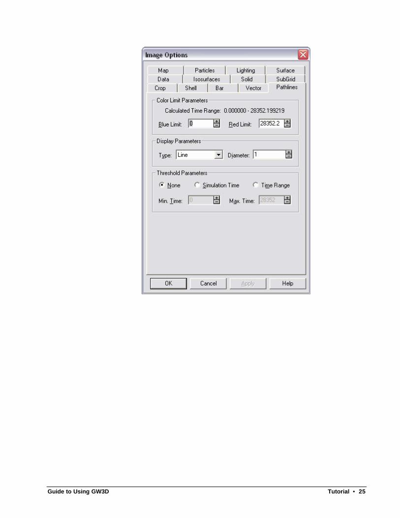
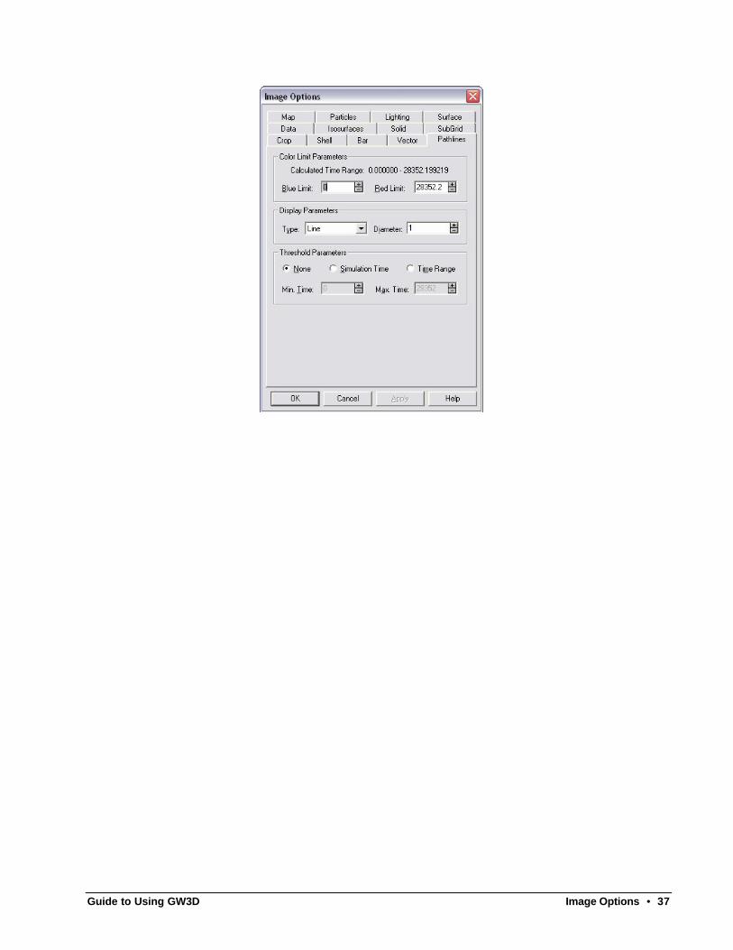
Pathlines Pathlines can be displayed as either lines or tubes. The only difference is that tubes are thicker and are easier to see. The colors are mapped from blue at early time to red at later times. You can control the values assigned to blue and red. You may also only show portions of the pathlines by clicking on “Time Range” at the bottom and then entering the minimum and maximum travel times to display.
Guide to Using GW3D Image Options • 37

38 • Command Reference Guide to Using GW3D
Command Reference
File Menu
New The New command on the File menu starts a new 3D image. You then need to select File/Import to bring in the data and results for a MODFLOW or MT3D run. You would normally not use this menu command, but rather use the command in Groundwater Vistas (3D\Launch GW3D) to start a new 3D image.
Open The Open command opens an existing GW3D document (*.gw3 extension) for viewing. Only documents created by GW3D can be opened. If you try to read a file that was created by a newer version of GW3D than you have, GW3D will display a warning to that effect. All subsequent revisions to Version 1 are free to download. Just go to our web site at www.groundwatermodels.com and log in.
Close The Close command closes the current GW3D document. GW3D is a mult-document interface and can open as many documents as there is sufficient memory for.
Save/Save As The Save command saves the current image to a GW3D document.
Print, Print Preview, Print Setup There are four menu selections related to printing the currently active view. These include Print , Print Preview, Print Setup, and Page Setup. The first three options are standard Windows menus and will work the same as your other Windows applications. The current view can be printed to any printer, plotter, fax modem, or other device supported by Windows. The only potential problem with printing is related to the rotated fonts used in type curve and contour labels. Some Windows
Guide to Using GW3D Command Reference • 39
device drivers do not properly support rotated fonts. It is very important to select Print Setup and choose the option to “Print TrueType as Graphics”. Most Windows device drivers will support this option, which allows for proper font rotation. If after selecting this option the type curve and contour labels are not properly rotated, you should call the manufacturer of your printer or other output device to get an updated Windows driver.
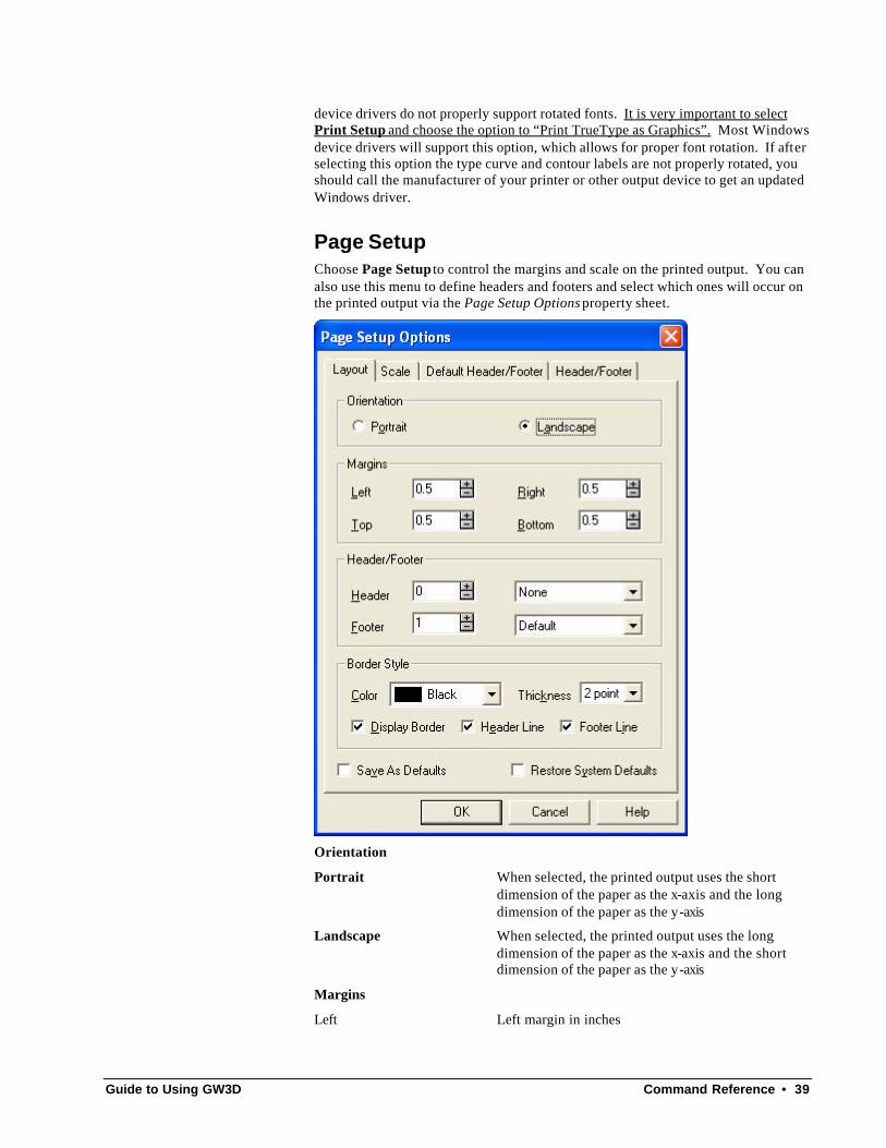
Page Setup Choose Page Setup to control the margins and scale on the printed output. You can also use this menu to define headers and footers and select which ones will occur on the printed output via the Page Setup Options property sheet.
Orientation
Portrait When selected, the printed output uses the short dimension of the paper as the x-axis and the long dimension of the paper as the y-axis
Landscape When selected, the printed output uses the long dimension of the paper as the x-axis and the short dimension of the paper as the y-axis
Margins
Left Left margin in inches

40 • Command Reference Guide to Using GW3D
Right Right margin in inches
Top Top margin in inches
Bottom Bottom margin in inches
Header/Footer
Header Space, in inches, between the top margin and printing area reserved for printing the header
Header combobox Specifies what to print in the header area if Header is greater than 0 inches
None – No header will be printed
Default – Uses the information on the Default Header/Footer page to construct the header
Custom - Stands for any number of user-designed header/footer elements
Footer Space, in inches, between the bottom margin and printing area reserved for printing the footer
Footer combobox Specifies what to print in the footer area if Footer is greater than 0 inches
None – No footer will be printed
Default – Uses the information on the Default Header/Footer page to construct the footer
Custom - Stands for any number of user-designed header/footer elements
Border Style
Color The color to use when displaying the border lines
Thickness The line thickness to use when displaying the border lines
Display Border When checked, a border line is displayed around the printable area defined by the margins
Header Line When checked, a border line is displayed separating the header area from the main printable area
Footer Line When checked, a border line is displayed separating the footer area from the main printable area
Save As Defaults When checked, the values contained in this property sheet are stored in the system registry when the property sheet is accepted and are used as the defaults when an new document is created
Restore System Defaults When checked, the default system values are restored when the property sheet is accepted; this operation occurs before the Save As Defaults operation so having both checked resets both the document and the system registry

Guide to Using GW3D Command Reference • 41
Title Block
Each of the four data fields and Font buttons define a line of text in the title block section
Bitmap File
File Name: The name of the file that was loaded for Bitmap and Metafile type frames
NOTE: The contents of the file are loaded and stored within the document so the file is no longer required and the name is for historical reference only.
Scale to Rectangle If checked, the bitmap is expanded/compressed to fill the frame
NOTE: This check-box is usually checked, otherwise, the screen display and printed output will not be the same.
Browse Click this button to display a standard File Open dialog used to locate the Bitmap or Metafile file stored on the computer.
Bitmap Size
Height Specifies the height, in inches, of the frame used to contain the bitmap or metafile

42 • Command Reference Guide to Using GW3D
Width Specifies the width, in inches, of the frame used to contain the bitmap or metafile
New: Creates a new header/footer and prompts for a name.
Rename: Prompts the user for a new name for the selected header/footer.
Add: Adds an item to the selected header/footer. The item selected in Item Type is added.
Edit: Edits the currently selected item.
Delete: Deletes the currently selected item.
Item Type: Specifies the currently active item to be added when the Add button is clicked.
NOTE: A context menu is provided to allow Cut/Copy/Paste of headers and footers to move them between documents.
Map Overlay GW3D can import maps created by Groundwater Vis tas. These files have *.map extension. You must be sure that the map file is in the proper coordinate system, otherwise it will not display properly. In all cases, you should first go into
Guide to Using GW3D Command Reference • 43
Groundwater Vistas, create the map using the File/Map command in Vistas. Once the map is displayed properly in GV, it can be displayed in GW3D for the same model. If you launch GW3D from Groundwater Vistas, all map files being displayed in Groundwater Vistas will also be displayed in GW3D.
Import The Import command allows you to start a new 3D image from an existing MODFLOW or MT3D simulation. Normally you would not use this command as it is easier to launch GW3D directly from Groundwater Vistas to start a new image.
Export The Export command creates three types of files, (1) a Windows metafile, (2) a placable Windows metafile, and (3) a VMRL World file for viewing in a 3D program other than GW3D. Simply supply a file name and GW3D will create the file.
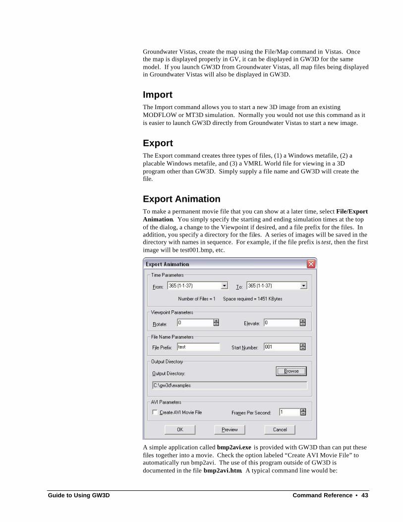
Export Animation To make a permanent movie file that you can show at a later time, select File/Export Animation. You simply specify the starting and ending simulation times at the top of the dialog, a change to the Viewpoint if desired, and a file prefix for the files. In addition, you specify a directory for the files. A series of images will be saved in the directory with names in sequence. For example, if the file prefix is test, then the first image will be test001.bmp, etc.
A simple application called bmp2avi.exe is provided with GW3D than can put these files together into a movie. Check the option labeled “Create AVI Movie File” to automatically run bmp2avi. The use of this program outside of GW3D is documented in the file bmp2avi.htm. A typical command line would be:
44 • Command Reference Guide to Using GW3D
bmp2avi –i test –o test –f 1
where “i” is the input name prefix, “o” is the output name (bmp2avi will attach a *.avi extension), and the number after “f” is the number of frames per second.
Send The Send command is used to email the current GW3D document using your default email software. You should make sure to save the current GW3D document before sending it.
Most Recently Used Files The four most recently opened document files are listed at the bottom of the File menu for easy access. Simply click on the appropriate file name in the menu and that file will be automatically opened.
Exit The Exit menu closes all open documents and exits the application. You will be prompted to optionally save each of the currently opened documents that has unsaved changes.
Edit Menu
Cut, Copy, Paste, Delete The Cut, Copy, Paste, and Delete menus are standard Windows functions. Each menu operates on the currently selected elements or spreadsheet lines. An element can be a well, title, line, frame, legend, symbol, parameter, or scale. To select one of these elements in a map view, simply move the cursor over the element until you
see the arrow appear, then click the left mouse button. The element will turn a solid color or a bounding rectangle will appear to identify that it has been selected. Multiple selection is achieved by repeating the procedure while holding down the Shift key. Now, all of the edit operations will work on this element. If no element has been selected, these menus will appear in gray and cannot be used. One exception is the Copy menu which allows copying the entire view to the clipboard as an OLE object and a metafile.
To select lines in a spreadsheet view, click the left mouse button in the leftmost column of the spreadsheet and drag a selection. Alternatively, hold down the shift key and use the arrow keys or page keys to expand the selection.
Use Cut to remove the selected elements or spreadsheet lines from the view and put
them on the Windows clipboard. You may also use the button on the Standard toolbar to cut. Use the Delete menu to simply remove the elements or spreadsheet lines from the view without placing them on the clipboard. Use Copy to keep the elements or spreadsheet lines in the view but make a copy on the Windows
clipboard. You may also use the button on the Standard toolbar to copy. You may put clipboard elements into the current view using the Paste menu selection or
Guide to Using GW3D Command Reference • 45
the button on the Standard toolbar. The items or lines are pasted back at the same coordinates as the original elements or before the currently selected line of the spreadsheet. These edit features are most useful to transfer elements from one document to another. You may have several analyses open at one time and cut, copy, and paste elements from one document to another.
During spreadsheet paste operations, the data is assumed to be in Windows text clipboard format with Tab characters separating data values and a newline character at the end of each data row. During spreadsheet cut and copy operations this same format is produced. Additionally, the order of the values in the clipboard corresponds to the order of the columns displayed on the spreadsheet. Since the number of and order of columns on the spreadsheet can be adjusted make sure the data matches the spreadsheet into which it will be pasted.
Select All The Select All menu is used to highlight all elements in a particular category. A third menu appears with the following categories: title, line, frame, legend, parameter, or symbol. You may want to select all instances of a particular element in order to cut/copy and then paste into another document.
Delete The Delete menu deletes the currently highlighted row of the spreadsheet or the currently selected block of rows. For a graph or map view, it deletes all selected elements.
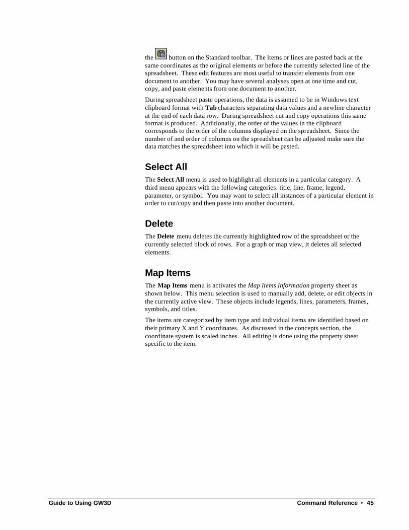
Map Items The Map Items menu is activates the Map Items Information property sheet as shown below. This menu selection is used to manually add, delete, or edit objects in the currently active view. These objects include legends, lines, parameters, frames, symbols, and titles.
The items are categorized by item type and individual items are identified based on their primary X and Y coordinates. As discussed in the concepts section, the coordinate system is scaled inches. All editing is done using the property sheet specific to the item.
46 • Command Reference Guide to Using GW3D
Add Adds an item to the currently active view. The item selected in Item Type is added.
Edit Edits the currently selected item.
Delete Deletes the currently selected item.
Item Type Specifies the currently active item to be added when the Add button is clicked.
Site The Site menu allows you to specify information describing the test site, including job number, client, etc. The menu item activates the Site Information property sheet. You may also specify the parameters describing each well used in the test, as described below.

Guide to Using GW3D Command Reference • 47
Site Designator User field that appears in the summary report and can be used to annotate a graph or map view.
Site Information
Job Number User field that appears in the summary report and can be used to annotate a graph or map view.
Client User field that appears in the summary report and can be used to annotate a graph or map view.
Site Name User field that appears in the summary report and can be used to annotate a graph or map view.
Additional Info: User field that appears in the summary report and can be used to annotate a graph or map view.

48 • Command Reference Guide to Using GW3D
The User tab contains customizable parameter boxes which allow the input of a wide range of user specified data or text items. Each field initially has a default name which can be changed. Place the cursor over the field name to be changed and right click the mo use. On the context menu displayed, select Edit and enter the new name required. Click on OK and the new name will be saved. The required information can then be entered into the input section of each box.
Information entered in these fields can be accessed in footers/headers, figures and parameter boxes displayed on graphical output.
3D Manipulation There are three options on the 3D Manipulation menu which determine how the 3D image is panned, zoomed, and/or rotated. Joy stick and mouse mode turn on the ability to manipulate the image. The Off option eliminates the ability to change the image using the mouse or joystick. When you first start GW3D, 3D Manipulation is in the Off mode. You can quickly turn on mouse mode by clicking the 3D button on the toolbar.
Reset, Save, Recall Viewpoint The “Save Viewpoint” command saves the current viewpoint. The saved viewpoint may be restored by using the “Restore Viewpoint” command. Note that the viewpoint is saved only temporarily and is discarded when the program terminates.

Guide to Using GW3D Command Reference • 49
View Menu
Standard Tools Selecting the Standard Tools menu toggles the display of the Standard toolbar. The display position of the toolbar is dependent on where it was previously located.
GW3D Tools Selecting the GW3D Tools menu toggles the display of the GW3D toolbar. The display position of the toolbar is dependent on where it was previously located.
Status Bar Selecting the Status Bar menu toggles the display of the status bar.
Toolbar Options
Display Options
Standard Tools When checked, the Standard Tools toolbar is displayed
GW3D Tools When checked, the GW3D Tools toolbar is displayed
Status Bar When checked, the Status Bar is displayed
Style Options
Display Parameters

50 • Command Reference Guide to Using GW3D
Rebar Style Specifies Rebar Style toolbars which are aligned along the top adjacent to one another and wrap to additional lines as the window size changes
Normal Style Specifies individual, dockable toolbars
Multi-Dock When checked, multiple toolbars can be combined into on floating toolbar frame; Not available for Rebar style or with flat buttons
Flat Buttons Specifies using the new flat looking toolbar buttons
Tooltips When checked, tooltips are active on toolbar buttons
Bitmap Menus When checked, the corresponding toolbar button bitmaps are displayed adjacent to menu items
Automatic Refresh The Automatic Refresh menu selection determines whether GW3D will redraw the window each time a dialog or property sheet is displayed or the window is resized, zoomed, or changed in any way. A checkmark appearing next to Auto Refresh means that the display is redrawn after every action that changes the display. Click on this menu to toggle the option on or off (with or without the checkmark). The default condition is Auto Refresh on. You may want to turn Auto Refresh off if you are making a lot of changes and your image is complex. On a fast computer, the refresh is fast enough that you probably will not care.
Refresh Selecting Refresh from the View menu causes the map window to be redrawn. You would use this feature if you have turned the Auto Refresh off (see last section) and the screen needs to be redrawn after a scroll or other action. You may also use the
Standard toolbar button.
Solid, Isosurface, None This section of the View menu determines whether the scalar data is displayed as a Solid, an Isosurface, or is not displayed at all.
Flow Vectors The Flow Vectors menu toggles display of velocity vectors.
Pathlines The Pathlines menu toggles display of particle tracks from MODPATH.
Model Features The Model Features menu toggles display of model boundary conditions.
Map Overlays The Map Overlays menu toggles display of base maps drawn on top of the image.

Guide to Using GW3D Command Reference • 51
View From Direction This menu contains a drop down list of + and – axes (x, y, and z). You can quickly change the view to be normal to one of the axis planes. For example, changing the view to +Z will change the view to the equivalent of the plan view in Groundwater Vistas.
View From Next Direction View From Next Direction loops through the items on the View From Direction menu.
Set Projection To The Set Projection to menu sets the projection mode to perspective or parallel. In perspective mode, parallel lines appear to converge to a point at infinity. This is the default projection mode. In parallel mode, parallel lines appear to remain parallel to each other as they extend to infinity. Parallel projection is of limited usefulness in three-dimensional visualization, but can be used to align grid nodes or to compare vector lengths.
Next Time Step The Next Time Step menu displays the next set of temporal data in a transient simulation. This is equivalent to the same command in Groundwater Vistas. If the current time step is the last one, then this menu item is grayed out.
Previous Time Step The Previous Time Step menu displays the time step immediately preceeding the time step that is currently being viewed. If the current time step is the first one, then this menu item is grayed out.
Add Menu The Add menu is for all views except the spreadsheet. These menus can also be selected from the GW3D toolbar shown below.
Title
Select the Title menu or choose the button on the GW3D toolbar to add text to the view. Move the cursor to the point where the text will be inserted and click the left mouse button or press the Enter key. The Title Information property sheet is presented prompting for the pertinent display characteristics. The x-coordinate and y-coordinate of the point are also provided in case you would like to override the values obtained from setting the location with the mouse or keyboard. In graph views, the coordinates are in inches from the lower left corner of the plot; in map

52 • Command Reference Guide to Using GW3D
views, the coordinates are in map units. Any number of titles may be added. Titles may also be embedded in Frames and Legends.
Title The text to display
Display Parameters
Color The color to use when displaying the text
Angle The angle to rotate the text around the location point
Alignment The alignment of the label relative to the location point
Font Defines the font, font style and size of the text
Spatial Parameters
X: The x-coordinate of the title location in the proper units
Y: The y-coordinate of the title location in the proper units
Parameter
Select the Parameter menu or choose the button on the GW3D toolbar to add parameter text to the view. Move the cursor to the point where the text will be inserted and click the left mouse button or press the Enter key. The Parameter Information property sheet is presented prompting for the pertinent display characteristics. The x-coordinate and y-coordinate of the point are also provided in case you would like to override the values obtained from setting the location with the mouse or keyboard. In graph views, the coordinates are in inches from the lower left corner of the plot; in map views, the coordinates are in map units. Any number of parameters may be added. Parameters may also be embedded in Frames and Legends.

Guide to Using GW3D Command Reference • 53
Parameter: A reference to the parameter to be displayed determined by the current selection
in the tree control
Display Parameters
Color The color to use when displaying the text
Angle The angle to rotate the text around the location point
Alignment The alignment of the label relative to the location point
Display Title If checked, the title of the parameter is displayed
Display Value If checked, the value of the parameter is displayed
Display Units If checked, the unit string of the parameter is displayed
Font Defines the font, font style and size of the text
Numeric Parameters
Format: The format to use when displaying numeric values
Precision: The number of digits after the decimal point
Spatial Parameters
X: The x-coordinate of the parameter location in the proper units
Y: The y-coordinate of the parameter location in the proper units
Symbol
Select the Symbol menu or choose the button on the GW3D toolbar to add a symbol to the view. Move the cursor to the point where the symbol will be inserted

54 • Command Reference Guide to Using GW3D
and click the left mouse button or press the Enter key. The Symbol Information property sheet is presented prompting for the pertinent display characteristics. The x-coordinate and y-coordinate of the point are also provided in case you would like to override the values obtained from setting the location with the mouse or keyboard. In graph views, the coordinates are in inches from the lower left corner of the plot; in map views, the coordinates are in map units. Any number of symbols may be added. Symbols may also be embedded in Frames, Legends and Header/Footer elements.
Symbol Style
Color The color to use when displaying the symbol
Thickness The line thickness to use when displaying the symbol
Symbol The symbol to display
Size The size of the symbol in points
Spatial Parameters
X: The x-coordinate of the symbol location in the proper units
Y: The y-coordinate of the symb ol location in the proper units
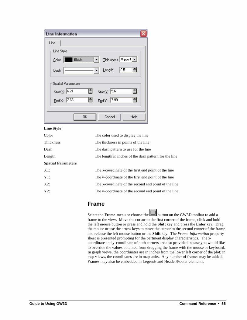
Line
Select the Line menu or choose the button on the GW3D toolbar to add a line to the view. Move the cursor to the point where the line will start, click and hold the left mouse button or press and hold the Shift key and press the Enter key. Drag the mouse or use the arrow keys to move the cursor to the point where the line should end and release the left mouse button or the Shift key. The Line Information property sheet is presented prompting for the pertinent display characteristics. The x-coordinate and y-coordinate of both end points are also provided in case you would like to override the values obtained from dragging the line with the mouse or keyboard. In graph views, the coordinates are in inches from the lower left corner of the plot; in map views, the coordinates are in map units. Any number of lines may be added. Lines may also be embedded in Frames, Legends and Header/Footer elements.
Guide to Using GW3D Command Reference • 55
Line Style
Color The color used to display the line
Thickness The thickness in points of the line
Dash The dash pattern to use for the line
Length The length in inches of the dash pattern for the line
Spatial Parameters
X1: The x-coordinate of the first end point of the line
Y1: The y-coordinate of the first end point of the line
X2: The x-coordinate of the second end point of the line
Y2: The y-coordinate of the second end point of the line
Frame
Select the Frame menu or choose the button on the GW3D toolbar to add a frame to the view. Move the cursor to the first corner of the frame, click and hold the left mouse button or press and hold the Shift key and press the Enter key. Drag the mouse or use the arrow keys to move the cursor to the second corner of the frame and release the left mouse button or the Shift key. The Frame Information property sheet is presented prompting for the pertinent display characteristics. The x-coordinate and y-coordinate of both corners are also provided in case you would like to override the values obtained from dragging the frame with the mouse or keyboard. In graph views, the coordinates are in inches from the lower left corner of the plot; in map v iews, the coordinates are in map units. Any number of frames may be added. Frames may also be embedded in Legends and Header/Footer elements.

56 • Command Reference Guide to Using GW3D
Line Style
Color The color used to display the optional border
Thickness: The thickness in points of the optional border
Dash The dash pattern to use for the optional border
Length The length in inches of the dash pattern for the optional border
Spatial Parameters
X1: The x-coordinate of the first corner of the frame
Y1: The y-coordinate of the first corner of the frame
X2: The x-coordinate of the second corner of the frame
Y2: The y-coordinate of the second corner of the frame

Guide to Using GW3D Command Reference • 57
Fill Type
Type Sets the type of fill to use within the frame
None The frame is not filled
Solid The frame is filled with a solid color
Hatch The frame is filled with a hatch pattern
Bitmap The frame is filled with a bitmap
Metafile The frame is filled with a metafile
Display Border If checked, a border line is displayed around perimeter of the frame
Background Color Selects the background color with which to fill the frame
Hatch Color/Pattern Selects the hatch color and hatch patter to use to fill Hatch type frames
File Information
File Name: The name of the file that was loaded for Bitmap and Metafile type frames
NOTE: The contents of the file are loaded and stored within the document so the file is no longer required and the name is for historical reference only.
Scale to Rectangle If checked, the bitmap is expanded/compressed to fill the frame
NOTE: This check-box is usually checked, otherwise, the screen display and printed output will not be the same.
Browse Click this button to display a standard File Open dialog used to locate the Bitmap or Metafile file stored on the computer.
Legend
Select the Legend menu or choose the button on the Annotation toolbar to add a frame to the view. Move the cursor to the first corner of the frame, click and hold the left mouse button or press and hold the Shift key and press the Enter key. Drag
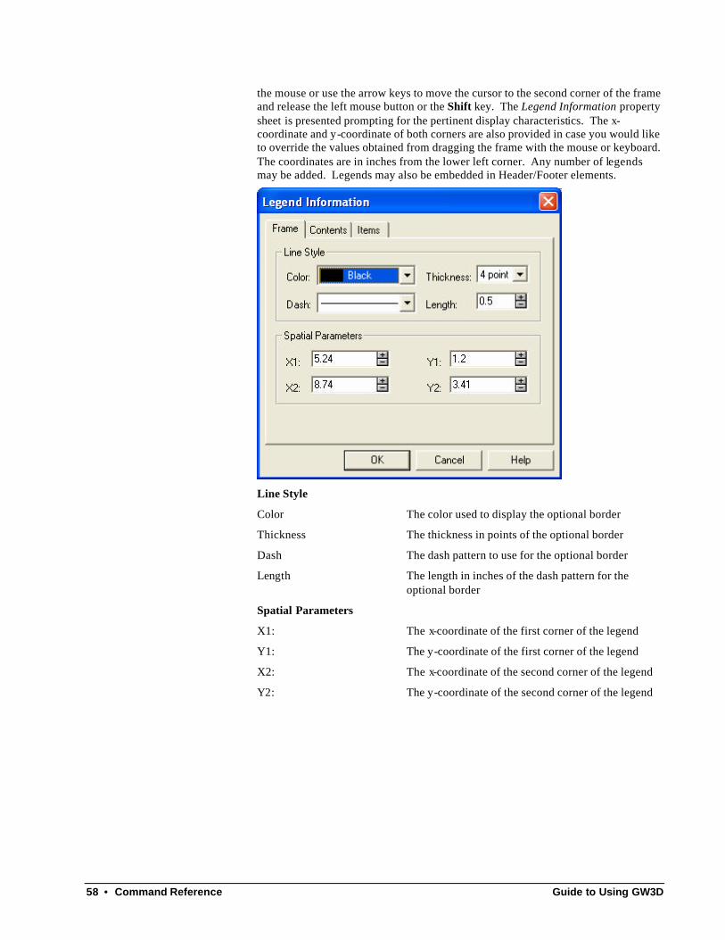
58 • Command Reference Guide to Using GW3D
the mouse or use the arrow keys to move the cursor to the second corner of the frame and release the left mouse button or the Shift key. The Legend Information property sheet is presented prompting for the pertinent display characteristics. The x-coordinate and y-coordinate of both corners are also provided in case you would like to override the values obtained from dragging the frame with the mouse or keyboard. The coordinates are in inches from the lower left corner. Any number of legends may be added. Legends may also be embedded in Header/Footer elements.
Line Style
Color The color used to display the optional border
Thickness The thickness in points of the optional border
Dash The dash pattern to use for the optional border
Length The length in inches of the dash pattern for the optional border
Spatial Parameters
X1: The x-coordinate of the first corner of the legend
Y1: The y-coordinate of the first corner of the legend
X2: The x-coordinate of the second corner of the legend
Y2: The y-coordinate of the second corner of the legend

Guide to Using GW3D Command Reference • 59
Fill Type
Type Sets the type of fill to use within the frame
None The frame is not filled
Solid The frame is filled with a solid color
Hatch The frame is filled with a hatch pattern
Bitmap The frame is filled with a bitmap
Metafile The frame is filled with a metafile
Display Border If checked, a border line is displayed around perimeter of the frame
Background Color Selects the background color with which to fill the frame
Hatch Color/Pattern Selects the hatch color and hatch patter to use to fill Hatch type frames
File Information
File Name: The name of the file that was loaded for Bitmap and Metafile type frames
NOTE: The contents of the file are loaded and stored within the document so the file is no longer required and the name is for historical reference only.
Scale to Rectangle If checked, the bitmap is expanded/compressed to fill the frame
NOTE: This check-box is usually checked, otherwise, the screen display and printed output will not be the same.
Browse Click this button to display a standard File Open dialog used to locate the Bitmap or Metafile file stored on the computer.

60 • Command Reference Guide to Using GW3D
Add: Adds an item, of the type selected in Item Type, to the legend
Edit: Presents the property sheet for the item selected in the tree control
Delete: Deletes the selected item currently selected in the tree control
Item Type: Specifies the currently active item to be added when the Add button is clicked
Guide to Using GW3D Command Reference • 61
The tree control on the Items tab has a context menu that allows you to Cut/Copy/Paste items within and across legend objects. Also, the Save As Default menu allows you to save the legend to be used as the default whenever another document is created to use this type of analysis. Refer to the Default Legend section for more details.
Options Menu
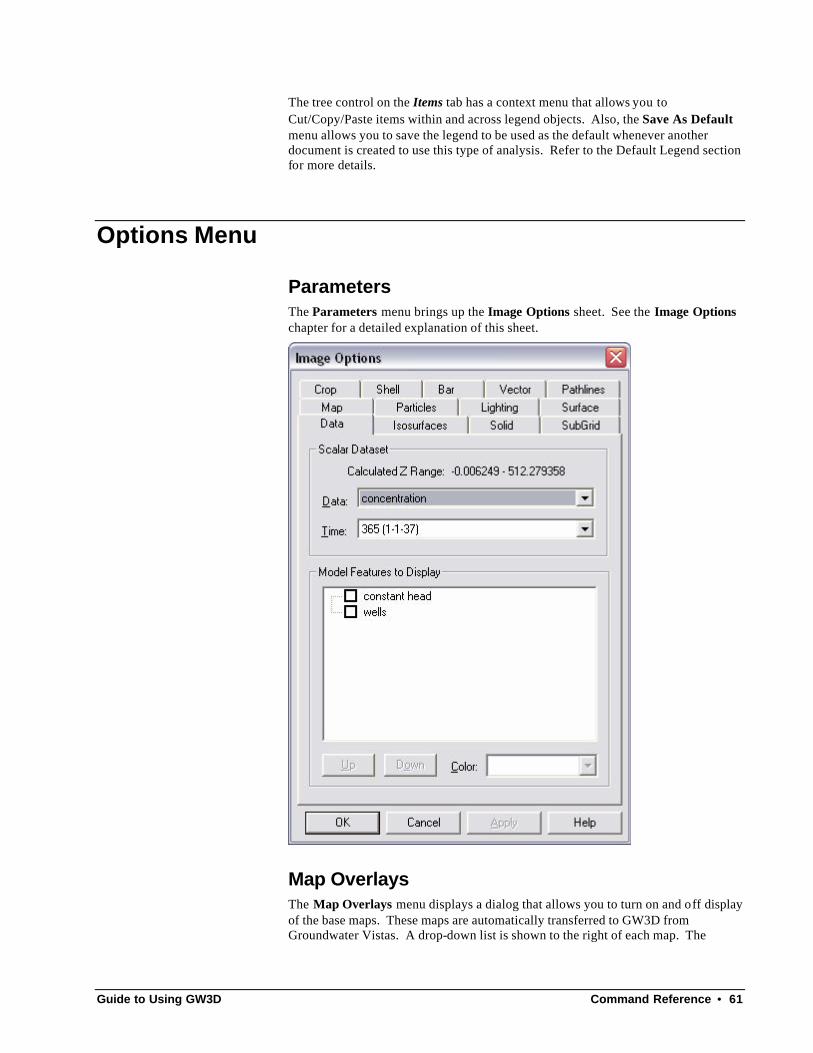
Parameters The Parameters menu brings up the Image Options sheet. See the Image Options chapter for a detailed explanation of this sheet.
Map Overlays The Map Overlays menu displays a dialog that allows you to turn on and off display of the base maps. These maps are automatically transferred to GW3D from Groundwater Vistas. A drop-down list is shown to the right of each map. The
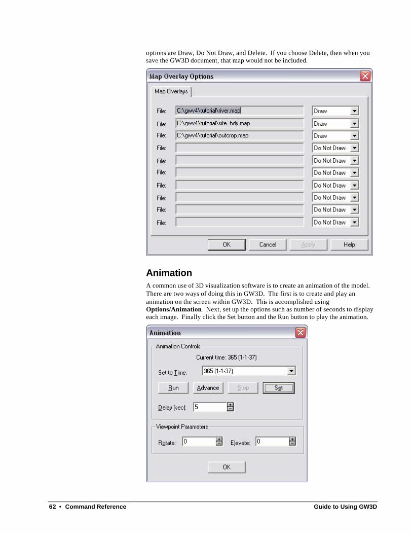
62 • Command Reference Guide to Using GW3D
options are Draw, Do Not Draw, and Delete. If you choose Delete, then when you save the GW3D document, that map would not be included.
Animation A common use of 3D visualization software is to create an animation of the model. There are two ways of doing this in GW3D. The first is to create and play an animation on the screen within GW3D. This is accomplished using Options/Animation. Next, set up the options such as number of seconds to display each image. Finally click the Set button and the Run button to play the animation.

Guide to Using GW3D Command Reference • 63
To make a permanent movie file that you can show at a later time, select File/Export Animation. Fill in similar options as for the animation technique described above. In addition, you specify a directory for the files and a root name for the image files. A series of images will be saved in the directory with names in sequence. For example, if the root name is test, then the firs image will be test001.bmp, etc.
A simple application called bmp2avi.exe is provided with GW3D than can put these files together into a movie. Check the option labeled “Create AVI Movie File” to automatically run bmp2avi. The use of this program outside of GW3D is documented in the file bmp2avi.htm. A typical command line would be:
bmp2avi –i test –o test –f 1
where “i” is the input name prefix, “o” is the output name (bmp2avi will attach a *.avi extension), and the number after “f” is the number of frames per second.
Assume All Active Cells By default GW3D shows the bounds of the image as the outside shell of the active cells in the model. Thus, no-flow (inactive) cells are not shown. You may change that by choosing the Assume All Active Cells menu. A checkmark next to this item will redraw the bounding surface on the outside of all grid cells.

64 • Command Reference Guide to Using GW3D
Window Menu
Cascade The Cascade menu arranges windows in an overlapped fashion. The windows are overlapped such that the corners of the windows align diagonally from the upper left corner of the frame window.
Tile Horizontally The Tile Horizontally menu arranges windows in non-overlapped tiles of equal size. If possible the windows will be arranged horizontally.
Tile Vertically The Tile Vertically menu arranges windows in non-overlapped tiles of equal size. If possible the windows will be arranged vertically.
Arrange Icons The Arrange Icons menu arranges the icons of closed windows along the bottom of the frame window.
Split The Split menu activates the separator between the panes of the active document window so it can be moved with the keyboard arrow keys.
Window 1, 2… This menu represents a currently open document window. The menu will activate the window and bring it to the foreground of the frame window.
Help Menu
Help Topics The Help Topics menu displays the online help for GW3D. The online help contains this entire manual with links established between the application and pertinent chapters and/or subchapters.

Guide to Using GW3D Command Reference • 65
What’s This? The What’s This? menu allows identification of another menu, toolbar button, etc. After selecting this menu, navigate the menus to locate the item you would like help on and click on it.
Tip of the Day The Tip of the Day menu displays the Tip of the Day dialog used to display suggestions or help about functionality in GW3D.
Show Tips on StartUp If checked, this dialog is displayed when the program is started
Next Tip Advances to the next suggestion or help item
Close Closes the dialog
About GW3D The About GW3D displays the About GW3D dialog as below. This dialog presents the program version number, credits and identifies the operating system the application is running on.

66 • Command Reference Guide to Using GW3D
The Register button, when clicked, is used to register the software by displaying the GW3D Registration dialog as below. The dialog displays a System Code which can be copied to the clipboard (you do this by highlighting the system code and pressing Ctrl-C) and pasted into an email to be sent to [email protected]. We will reply with a security code that you paste or enter into the Security Code field in the above dialog. Alternatively, you can get a security code by calling either ESI in the United States at (610) 670-3400 or ESL in the United Kingdom at +44 1743 280020; however, it is strongly recommended that the transaction be done via email since the codes are rather long.
Security Code: This is an encrypted code containing information about your software license
and the configuration of the computer used to validate the license
Authorization Level: The level of functionality of the application granted by the license
System Code: This is an encrypted code containing information about your hardware configuration used to generate a unique Security Code

Guide to Using GW3D Command Reference • 67

68 • References Guide to Using GW3D
References
Hsieh, P.A. and R.B. Winston, 2002, User’s Guide to Model Viewer, A Program for Three-Dimensional Visualization of Ground-Water Model Results, USGS Open File Report 02-106.
Schroeder, W., K. Martin, and B. Lorensen, 1997, The Visualization Toolkit, An Object-Oriented Approach to 3D Graphics, Kitware, Inc.
Schroeder, W.J., L.S. Avila, K.M Martin, W.A. Hoffman, and C.C. Law, 2001, The VTK User’s Guide, Kitware, Inc.

Guide to Using GW3D Index • 69
Index
A
About AquiferWin32 48 About GW3D 65 About GW3D dialog 65 Add menu 51
Frame 55 Legend 57 Line 54 Parameter 52 Symbol 53 Title 51
Arrange Icons 64 Automatic Refresh 50
C
Cascade 64 Copy 44 Cut 44
D
Delete 44, 45
E
Edit menu Copy 44 Cut 44 Delete 44, 45 Map Items 45 Paste 44 Select All 45 Site 46
Exit 44
F
File menu Exit 44
Page Setup 39 Print 38 Print Preview 38 Print Setup 38
Frame 55 Frame Information property sheet 55
G
Groundwater Vistas Installation Error! Not a valid bookmark in entry
on page 1 technical support 1, 3
GW3D Tools 49
H
Help 1 Help Menu
About GW3D 65 Help Topics 64 Tip of the Day 65 What's This 65
Help Topics 64
I
installation Error! Not a valid bookmark in entry on page 1
L
Legend 57 Legend Information property sheet 58 Line 54 Line Information property sheet 54
M
Map Items 45 Map Items Information property sheet 45 Models
MODFLOW Error! Not a valid bookmark in entry on page 13
MODFLOW Error! Not a valid bookmark in entry on page 13
P
Page Setup 39 Page Setup Options property sheet 39 Parameter 52 Parameter Information property sheet 52 Paste 44 Print 38 Print Preview 38

70 • Index Guide to Using GW3D
Print Setup 38
R
Refresh 50 Register 66
S
Select All 45 site 46 Site Information property sheet 46 Split 64 Standard Tools 49 Status Bar 49 Symbol 53 Symbol Information property sheet 54 system code 66
T
technical support 1, 3 Tile Horizontally 64 Tile Vertically 64 Tip of the Day 65 Tip of the Day dialog 65 Title 51 Title Information property sheet 51
V
View Menu Automatic Refresh 50 GW3D Tools 49 Refresh 50 Standard Tools 49 Status Bar 49
W
What's This 65 Window Menu
Arrange Icons 64 Cascade 64 Split 64 Tile Horizontally 64 Tile Vertically 64