Embed Size (px)
Citation preview
Installation, Operation & Maintenance Manual
the
Intelligent Defrost Control System
by
ENTER
BACK
22
by Century Refrigeration
2
THEORY OF OPERATION
The Centinel™ Intelligent Defrost Control System is an electronically operated evaporator controller designed to save energy in refrigeration systems. The Centinel™ reduces the energy used by the system by precisely controlling superheat and fans, reducing compressor run time, and implementing demand defrosts. The Centinel™ was designed for a quick payback and a life expectancy that matches that of the system. The controller pays for itself, and then continues to pay dividends for the life of the system.
REFRIGERATION SYSTEM
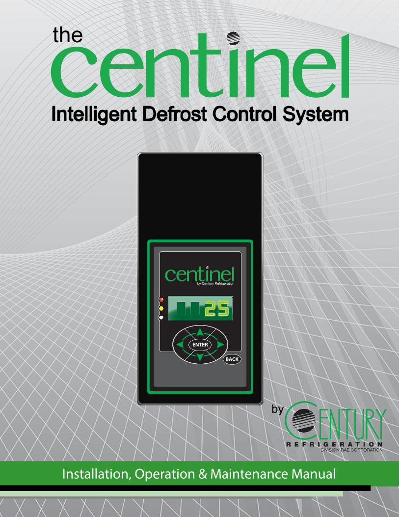
Century Refrigeration is the industry specialist in systems-based approaches to your entire refrigeration project. A brief introduction to these refrigeration systems is necessary before discussing the Centinel™ and its functions. A refrigeration system is defined as a group of devices designed to transfer heat from an enclosed space to an external location. As shown in Figure 1, a refrigeration system is comprised of four main components: the evaporator, the condenser, the compressor, and the expansion device.
The system’s cycle begins at the compressor. A compressor is a motor-driven device that converts low pressure refrigerant vapor into high pressure refrigerant vapor. This is accomplished when the low pressure vapor enters the suction valve, is mechanically reduced in volume, increases in pressure, and exits through the
discharge valve. The heat created as a result of the increase in vapor pressure must be removed to change the physical state of the vapor to liquid.
The condenser removes the heat generated by this compression of the vapor by transferring it to another medium, typically air or water. As the heat is removed from the refrigerant vapor, it begins to change state from a gas to a liquid. Upon exiting the condenser, the refrigerant is in a 100% liquid state. As this liquid exits the condenser, it travels through the system piping to the expansion device.
The expansion device is the divider between the high pressure (“high”) and low pressure (“low”) sides of the system. The expansion device controls the amount of refrigerant supplied to the evaporator coil. As the refrigerant passes through the expansion device, it enters the “low” side of the system. At this lower pressure, the refrigerant begins to bubble and is transformed into a two-phase liquid. This two-phase refrigerant continues to absorb heat in the evaporator.
The evaporator transfers heat from the enclosed space to the desired refrigerant medium (air, water, glycol, etc.) Meanwhile, the expansion device continues to control the refrigerant flow, ensuring all the liquid has fully vaporized prior to leaving the evaporator. Upon exiting the evaporator, the vapor continues to the compressor where the cycle begins again.
Expansion Device (Restrictor,TEV, or EEV)
Evaporator
Compressor
Condenser
Figure 1 - Basic Refrigeration System
3
THE EVAPORATOR
The evaporator consists of an evaporator (DX) coil, fans, expansion device, and defrost heaters. It may also include the liquid line solenoid valve. By carefully managing each component of the evaporator, the Centinel™ is able to provide a maximum output using a minimum amount of energy.
When the temperature of the evaporator drops below the dew point, moisture begins to collect on the cool surfaces of the evaporator. If the temperature continues to drop below freezing, this moisture will begin to solidify and form a thin layer of ice on the evaporator. As more moisture builds on this ice, frost begins to form. The frost layer closest to the surface of the evaporator will tend to be hard, with a consistency similar to an ice cube. Depending on humidity, evaporator temperature, and air flow, subsequent layers of frost may be more crystalline or snow-like. This is referred to as radiant frost or hoar frost.
There are several factors that influence frost building on an evaporator:
• The thermal conductivity (K value) of the coil• Atmospheric Conditions• Product Humidity• Coil Location• Plant Design
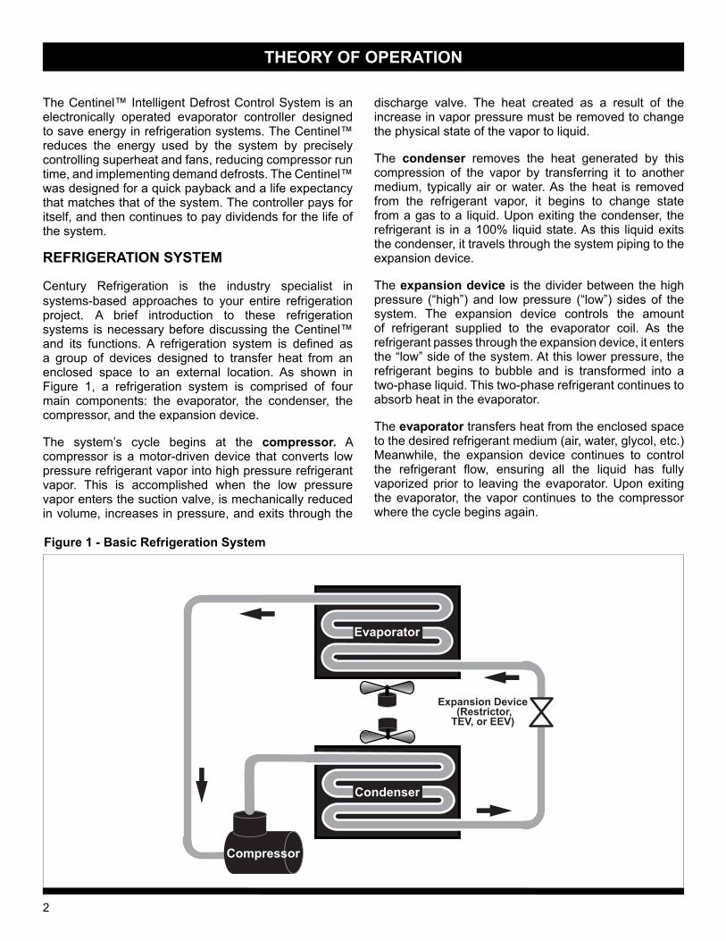
Although building frost on evaporator coils is unavoidable, it ultimately causes the evaporator to lose efficiency. Initially, frost increases the capacity of the evaporator. This efficiency boost is due to the increased surface area the frost adds to the coil. However, as the frost continues to build, more and more air is trapped between the
ambient air and the coil, creating an insulating effect. Due to this insulating effect, the temperature of the coil must be reduced to maintain the desired space temperature. When the temperature difference (TD) increases, it causes the evaporator coil to accelerate the formation of frost. Figure 2 illustrates how the evaporator performance is enhanced by frost initially, but declines over time.
To reduce the TD and the formation of frost, the Centinel™ controller creates a coil profile for each of the system’s evaporators. This is achieved by using unique, self-learning algorithms to control the evaporator fans based on the system’s coil and air temperatures. Once the Centinel™ has learned the most efficient method of controlling the evaporator, it uses special fan control techniques to extract energy stored in the coil. This stored energy is not recognized by traditional defrost controls. By maintaining a lower TD throughout the evaporator’s run time, the Centinel™ leads to a slower rate of frost build-up and extends the time between defrosts cycles.
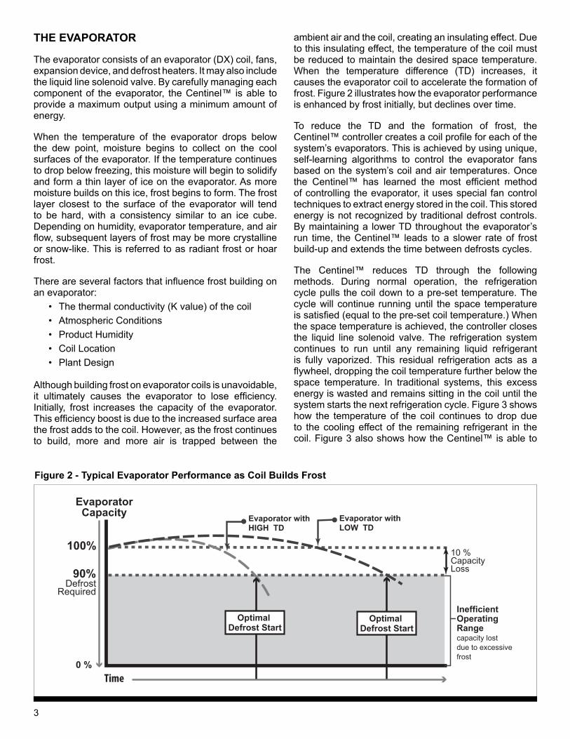
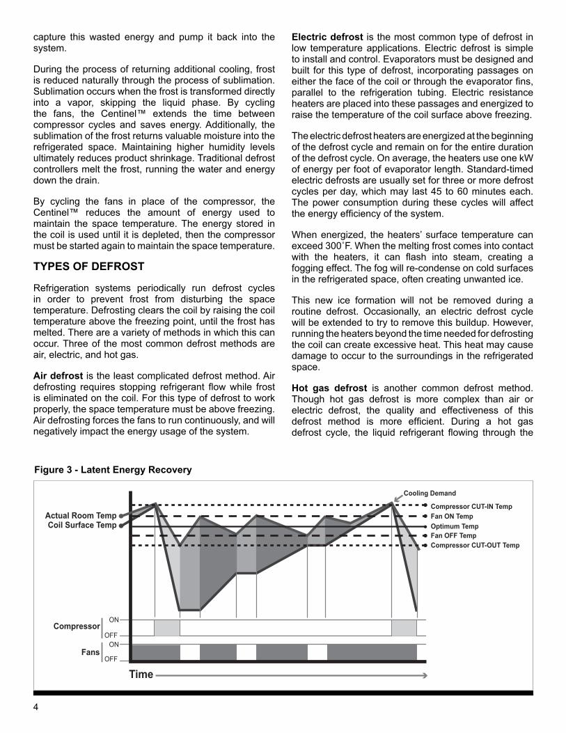
The Centinel™ reduces TD through the following methods. During normal operation, the refrigeration cycle pulls the coil down to a pre-set temperature. The cycle will continue running until the space temperature is satisfied (equal to the pre-set coil temperature.) When the space temperature is achieved, the controller closes the liquid line solenoid valve. The refrigeration system continues to run until any remaining liquid refrigerant is fully vaporized. This residual refrigeration acts as a flywheel, dropping the coil temperature further below the space temperature. In traditional systems, this excess energy is wasted and remains sitting in the coil until the system starts the next refrigeration cycle. Figure 3 shows how the temperature of the coil continues to drop due to the cooling effect of the remaining refrigerant in the coil. Figure 3 also shows how the Centinel™ is able to
100%
90%
Time
EvaporatorCapacity
DefrostRequired
0 %
Inefficient Operating Rangecapacity lost due to excessive frost
Evaporator with LOW TD
Evaporator with HIGH TD
10 % Capacity Loss
Optimal Defrost Start
Optimal Defrost Start
Figure 2 - Typical Evaporator Performance as Coil Builds Frost
4
capture this wasted energy and pump it back into the system.
During the process of returning additional cooling, frost is reduced naturally through the process of sublimation. Sublimation occurs when the frost is transformed directly into a vapor, skipping the liquid phase. By cycling the fans, the Centinel™ extends the time between compressor cycles and saves energy. Additionally, the sublimation of the frost returns valuable moisture into the refrigerated space. Maintaining higher humidity levels ultimately reduces product shrinkage. Traditional defrost controllers melt the frost, running the water and energy down the drain.
By cycling the fans in place of the compressor, the Centinel™ reduces the amount of energy used to maintain the space temperature. The energy stored in the coil is used until it is depleted, then the compressor must be started again to maintain the space temperature.
TYPES OF DEFROST
Refrigeration systems periodically run defrost cycles in order to prevent frost from disturbing the space temperature. Defrosting clears the coil by raising the coil temperature above the freezing point, until the frost has melted. There are a variety of methods in which this can occur. Three of the most common defrost methods are air, electric, and hot gas.
Air defrost is the least complicated defrost method. Air defrosting requires stopping refrigerant flow while frost is eliminated on the coil. For this type of defrost to work properly, the space temperature must be above freezing. Air defrosting forces the fans to run continuously, and will negatively impact the energy usage of the system.
Electric defrost is the most common type of defrost in low temperature applications. Electric defrost is simple to install and control. Evaporators must be designed and built for this type of defrost, incorporating passages on either the face of the coil or through the evaporator fins, parallel to the refrigeration tubing. Electric resistance heaters are placed into these passages and energized to raise the temperature of the coil surface above freezing.
The electric defrost heaters are energized at the beginning of the defrost cycle and remain on for the entire duration of the defrost cycle. On average, the heaters use one kW of energy per foot of evaporator length. Standard-timed electric defrosts are usually set for three or more defrost cycles per day, which may last 45 to 60 minutes each. The power consumption during these cycles will affect the energy efficiency of the system.
When energized, the heaters’ surface temperature can exceed 300˚F. When the melting frost comes into contact with the heaters, it can flash into steam, creating a fogging effect. The fog will re-condense on cold surfaces in the refrigerated space, often creating unwanted ice.
This new ice formation will not be removed during a routine defrost. Occasionally, an electric defrost cycle will be extended to try to remove this buildup. However, running the heaters beyond the time needed for defrosting the coil can create excessive heat. This heat may cause damage to occur to the surroundings in the refrigerated space.
Hot gas defrost is another common defrost method. Though hot gas defrost is more complex than air or electric defrost, the quality and effectiveness of this defrost method is more efficient. During a hot gas defrost cycle, the liquid refrigerant flowing through the
TimeOFF
ONOFF
ON
Fans
Coil Surface TempActual Room Temp
Compressor
Fan OFF Temp
Fan ON Temp
Cooling Demand
Compressor CUT-IN Temp
Compressor CUT-OUT Temp
Optimum Temp
Figure 3 - Latent Energy Recovery
5
evaporator is interrupted and replaced by “gas“ directly from the discharge of the compressor. This “gas” is actually a superheated, compressed refrigerant vapor and can easily exceed 200˚F. Because the heat source is supplied from inside the tubes of the coil, it applies heat directly to the frost where it forms on the tubes. The hot gas travels throughout the entire refrigerant tubing circuit, and will defrost areas of the evaporator that are not reached as effectively by electric resistance heaters.
During electric and hot gas defrosts, the fans should be off. Fans must then remain off for a period of time after the defrost cycle is terminated. During these defrosts, water is formed on the evaporator as the ice melts. Once the defrost cycle terminates, water must be allowed to drain from the coil. This period is known as the evaporator’s “drip time.” “Drip time” prevents moisture from being blown off the coil only to refreeze on the cold product or other surfaces in the space.
Within these three different types of defrosts methods, there are also different types of defrost controls:
Time-initiated, time-terminated defrosts are the most effective defrost controls when conditions are consistent in the system and in the space. Consistent conditions will allow the minimum number of defrost cycles per day with minimum cycle run time. Unfortunately, refrigerated spaces rarely have consistent conditions due to space access, product loading, seasonality, etc. The defrost schedule must be setup to handle these inconsistent conditions. This is inefficient most of the time.
Time-initiated, temperature-terminated defrosts are more efficient than the time-time method described above. Time-temperature defrost controllers can be mechanically or electronically controlled. By terminating defrost based on temperature, the defrost heaters reduce excess heat transferred into the controlled space. However, this type of defrost control still requires additional, unnecessary, defrost cycles to be performed on the system in anticipation of inconsistent conditions. Some time-temperature control models measure the length of compressor run time to estimate the proper time to defrost the system.
Advanced time defrosts rely on time to initiate defrost cycles. These controls use a variety of techniques to measure run time of the system, but have limited effectiveness when applied in the field. A set of algorithms is used to estimate the reaction of the system to a series of events. By using these estimates, the system owner will plan around inconsistent system and space conditions, resulting in a loss of system efficiency. These controls are also susceptible to resets due to power outages.
The Centinel™ Intelligent Defrost Control approaches defrost control in a revolutionary way. The Centinel™ uses a special defrost control algorithm which eliminates the dependency on time. The Centinel™ monitors the
efficiency of the system and determines the optimum time for the system to run a defrost cycle.
HOW THE CENTINEL™ WORKS
The Centinel™ utilizes a unique, self-learning algorithm to maximize energy efficiency, while minimizing the effects of defrosts on the space temperature.
To extend the time between defrost cycles, the Centinel™ first reduces the amount of frost that builds up on the coil. The controller can then monitor the coil performance and extend the time between defrosts from hours to days, or back to hours depending on the system conditions. Secondly, the Centinel™ monitors the coil’s efficiency and only calls for a defrost cycle when it is necessary, rather than when time calls for it. Fewer defrost cycles eliminates associated temperature spikes. This provides a more uniform product temperature, helping to reduce product shrinkage.
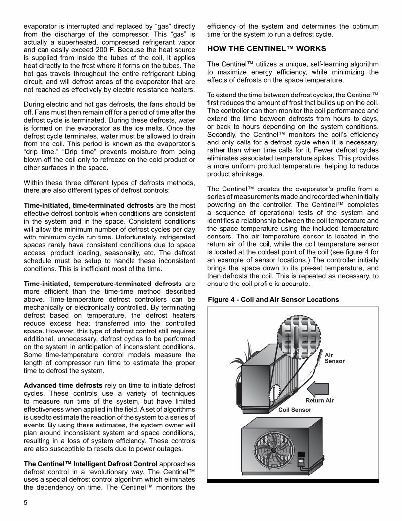
The Centinel™ creates the evaporator’s profile from a series of measurements made and recorded when initially powering on the controller. The Centinel™ completes a sequence of operational tests of the system and identifies a relationship between the coil temperature and the space temperature using the included temperature sensors. The air temperature sensor is located in the return air of the coil, while the coil temperature sensor is located at the coldest point of the coil (see figure 4 for an example of sensor locations.) The controller initially brings the space down to its pre-set temperature, and then defrosts the coil. This is repeated as necessary, to ensure the coil profile is accurate.
Coil Sensor
Air Sensor
Return Air
2222
ENTER
BACK
by Century Refrigeration
22
Figure 4 - Coil and Air Sensor Locations
6
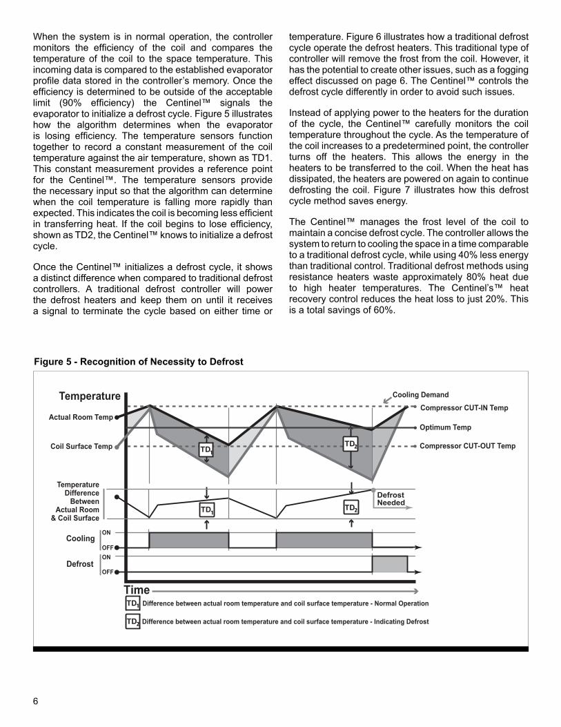
When the system is in normal operation, the controller monitors the efficiency of the coil and compares the temperature of the coil to the space temperature. This incoming data is compared to the established evaporator profile data stored in the controller’s memory. Once the efficiency is determined to be outside of the acceptable limit (90% efficiency) the Centinel™ signals the evaporator to initialize a defrost cycle. Figure 5 illustrates how the algorithm determines when the evaporator is losing efficiency. The temperature sensors function together to record a constant measurement of the coil temperature against the air temperature, shown as TD1. This constant measurement provides a reference point for the Centinel™. The temperature sensors provide the necessary input so that the algorithm can determine when the coil temperature is falling more rapidly than expected. This indicates the coil is becoming less efficient in transferring heat. If the coil begins to lose efficiency, shown as TD2, the Centinel™ knows to initialize a defrost cycle.
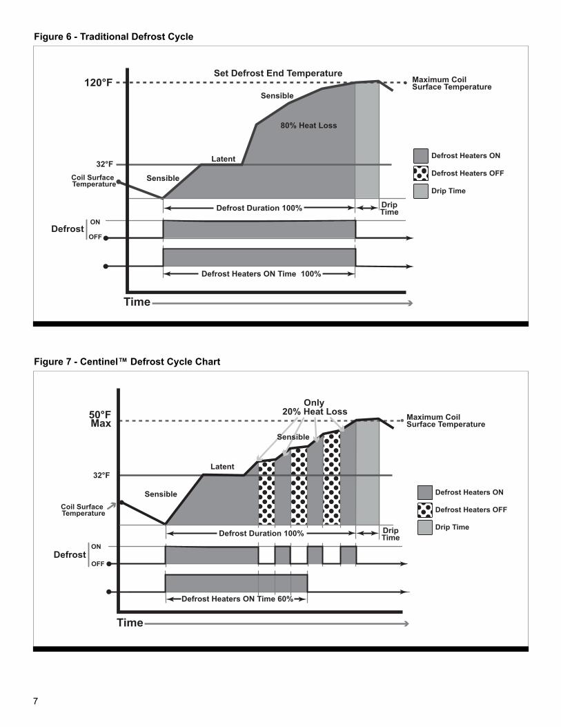
Once the Centinel™ initializes a defrost cycle, it shows a distinct difference when compared to traditional defrost controllers. A traditional defrost controller will power the defrost heaters and keep them on until it receives a signal to terminate the cycle based on either time or
temperature. Figure 6 illustrates how a traditional defrost cycle operate the defrost heaters. This traditional type of controller will remove the frost from the coil. However, it has the potential to create other issues, such as a fogging effect discussed on page 6. The Centinel™ controls the defrost cycle differently in order to avoid such issues.
Instead of applying power to the heaters for the duration of the cycle, the Centinel™ carefully monitors the coil temperature throughout the cycle. As the temperature of the coil increases to a predetermined point, the controller turns off the heaters. This allows the energy in the heaters to be transferred to the coil. When the heat has dissipated, the heaters are powered on again to continue defrosting the coil. Figure 7 illustrates how this defrost cycle method saves energy.
The Centinel™ manages the frost level of the coil to maintain a concise defrost cycle. The controller allows the system to return to cooling the space in a time comparable to a traditional defrost cycle, while using 40% less energy than traditional control. Traditional defrost methods using resistance heaters waste approximately 80% heat due to high heater temperatures. The Centinel’s™ heat recovery control reduces the heat loss to just 20%. This is a total savings of 60%.
Time
TD
OFF
ONOFF
ON
Defrost
Coil Surface Temp
Actual Room Temp
Cooling
Cooling DemandCompressor CUT-IN Temp
Compressor CUT-OUT Temp
Optimum Temp
Temperature
Defrost Needed
TemperatureDifference
BetweenActual Room
& Coil SurfaceTD
TD
TD
TD
TD
Difference between actual room temperature and coil surface temperature - Normal Operation
Difference between actual room temperature and coil surface temperature - Indicating Defrost
Figure 5 - Recognition of Necessity to Defrost
7
Time
OFF
ONDefrost
32°F
120°F
Coil Surface Temperature
Maximum Coil Surface Temperature
Defrost Heaters ON Time 100%
Defrost Heaters OFF
Defrost Duration 100%
Latent
Sensible
Sensible
Defrost Heaters ON
Drip Time
DripTime
80% Heat Loss
Set Defrost End Temperature
Figure 6 - Traditional Defrost Cycle
Only 20% Heat Loss
Defrost Heaters OFF
Defrost Heaters ON
Drip Time
OFF
ONDefrost
32°F
50°FMax
Coil Surface Temperature
Time
Defrost Heaters ON Time 60%
Defrost Duration 100%
Maximum Coil Surface Temperature
DripTime
Latent
Sensible
Sensible
Figure 7 - Centinel™ Defrost Cycle Chart
8
CENTINEL™ VALVE CONTROL
The Centinel™ Intelligent Defrost Control offers the latest in electronic expansion valve (EEV) control technology. The Centinel’s™ EEV is designed to maximize the evaporator efficiency by maintaining precise superheat control.
The addition of a Centinel™ EEV can easily provide additional savings to the end user. However, thermal expansion valves (TEVs) are already installed on many existing Century Refrigeration units. TEVs provide consistent control on those systems and are not required to be replaced. The Centinel™ can be used effectively on TEV-controlled systems without the need to break into the system.
Installing a Centinel™ EEV on your Century Refrigeration units offers several advantages to the end user. Since the Centinel™ EEV does not require a pressure differential to operate, the EEV controls down to 10% of the total capacity of the valve. A traditional TEV can only control down to 50% capacity. This allows the system to operate at lower head pressures during times of lower ambient temperatures.
Since condenser capacities are designed for the highest ambient temperatures of the year, they are oversized during lower ambient temperatures. Mechanical valves require controls to raise the head pressure to maintain the pressure drop required by the TEV. The ability of the Centinel™ EEV to reduce the head pressure increases the energy savings of the system.
CENTINEL™ COMMUNICATION
One of the many benefits of the Centinel™ is the ability for owners and contractors to remotely view a refrigeration system’s performance. This information is invaluable as it can potentially save time and money in service calls.
Century Refrigeration approaches communications in a unique and revolutionary way. In the Centinel™ Refrigeration Network, the costly Serial Gateway is not needed to manage, monitor and communicate with refrigeration controllers. All Centinel™ controllers are Ethernet network devices, which is the standard of choice in most markets. The Centinel™ supports industry standard protocols (i.e. TCP/IP), can easily be plugged into an existing network, natively supports remote access, and can be managed via a web page.
9
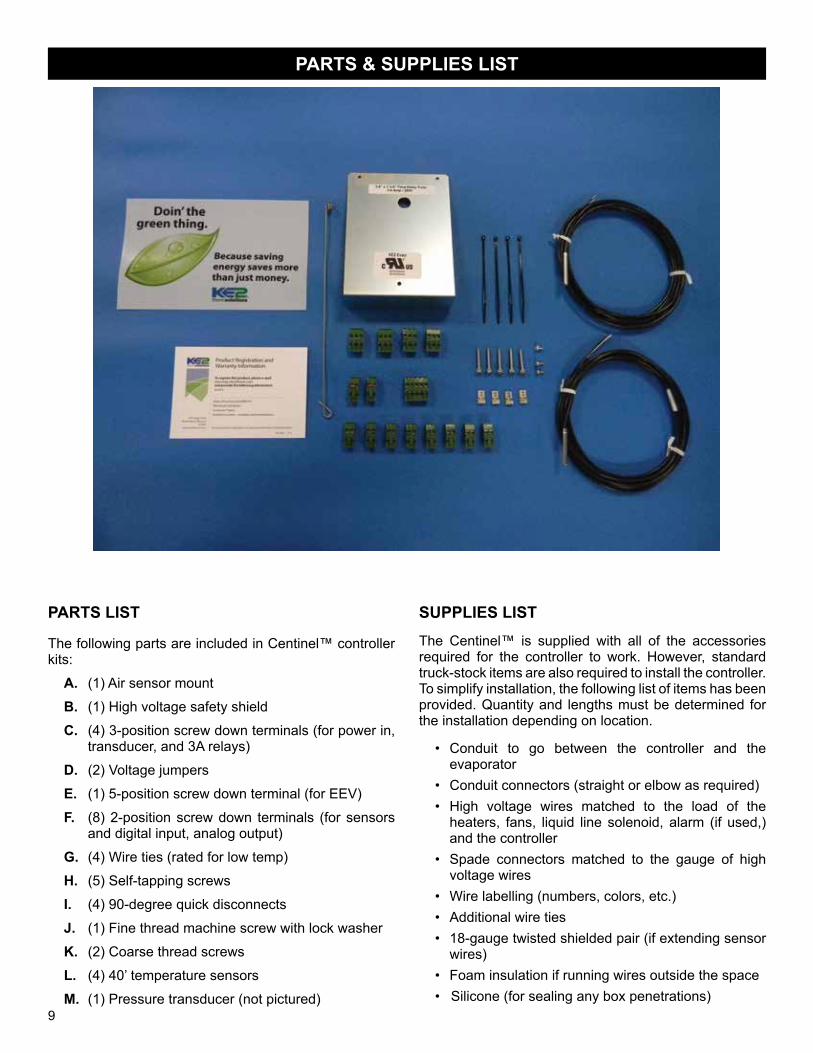
PARTS LIST
The following parts are included in Centinel™ controller kits:
A. (1) Air sensor mount
B. (1) High voltage safety shield
C. (4) 3-position screw down terminals (for power in, transducer, and 3A relays)
D. (2) Voltage jumpers
E. (1) 5-position screw down terminal (for EEV)
F. (8) 2-position screw down terminals (for sensors and digital input, analog output)
G. (4) Wire ties (rated for low temp)
H. (5) Self-tapping screws
I. (4) 90-degree quick disconnects
J. (1) Fine thread machine screw with lock washer
K. (2) Coarse thread screws
L. (4) 40’ temperature sensors
M. (1) Pressure transducer (not pictured)
SUPPLIES LISTThe Centinel™ is supplied with all of the accessories required for the controller to work. However, standard truck-stock items are also required to install the controller. To simplify installation, the following list of items has been provided. Quantity and lengths must be determined for the installation depending on location.
• Conduit to go between the controller and the evaporator
• Conduit connectors (straight or elbow as required)• High voltage wires matched to the load of the
heaters, fans, liquid line solenoid, alarm (if used,) and the controller
• Spade connectors matched to the gauge of high voltage wires
• Wire labelling (numbers, colors, etc.)• Additional wire ties• 18-gauge twisted shielded pair (if extending sensor
wires)• Foam insulation if running wires outside the space• Silicone (for sealing any box penetrations)
PARTS & SUPPLIES LIST
10
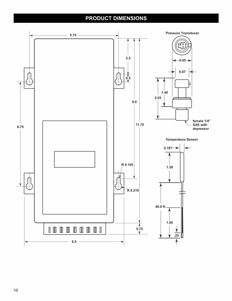
PRODUCT DIMENSIONS
R 0.210
R 0.105
11.75
9.0
0.5
2.2
Pressure Transducer
0.75
6.75
1.40
2.03
0.67
0.95
5.75
2.03
6.5
female 1/4” SAE with depressor
Temperature Sensor
40.0 ft.
.25
1.50
1.50
0.187
11
FIELD INSTALLATION GUIDE
The instructions that follow are for field installation of the Centinel™ Intelligent Defrost Control. For factory mounted controllers, see page 24.
ARRIVING AT THE JOB SITE
Inspect the evaporator coil to see the current frost pattern. If the unit has not recently performed a defrost, look for the heaviest area of frost. This will be used to place the coil temperature sensors.
Remove the evaporator end covers.
Installers should account for a full system diagnostic in the installation estimate for the controller.
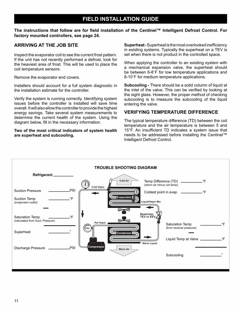
Verify the system is running correctly. Identifying system issues before the controller is installed will save time overall. It will also allow the controller to provide the highest energy savings. Take several system measurements to determine the current health of the system. Using the diagram below, fill in the necessary information.
Two of the most critical indicators of system health are superheat and subcooling.
Superheat - Superheat is the most overlooked inefficiency in existing systems. Typically the superheat on a TEV is set when there is not product in the controlled space.
When applying the controller to an existing system with a mechanical expansion valve, the superheat should be between 6-8˚F for low temperature applications and 8-10˚F for medium temperature applications.
Subcooling - There should be a solid column of liquid at the inlet of the valve. This can be verified by looking at the sight glass. However, the proper method of checking subcooling is to measure the subcooling of the liquid entering the valve.
VERIFYING TEMPERATURE DIFFERENCE
The typical temperature difference (TD) between the coil temperature and the air temperature is between 5 and 15°F. An insufficient TD indicates a system issue that needs to be addressed before installing the Centinel™ Intelligent Defrost Control.
Restrictor,TEV or EEV
Evaporator
Compressor
Condenser
Cold Air
Warm Air
Cold Vapor
Hot Vapor
Warm Liquid
Liquid/Vapor Mix
TROUBLE SHOOTING DIAGRAM
Refrigerant
Suction Pressure
Suction Temp(evaporator outlet)
Saturation Temp(calculated from Suct. Pressure)
Superheat
Discharge Pressure
PSI
°F
°F
°
PSI
Temp Difference (TD)(return air minus coil temp)
Coldest point in evap
°F
°F
Saturation Temp(from receiver pressure)
Liquid Temp at Valve
Subcooling
°F
°F
°
12
INSTALLATION INSTRUCTIONS
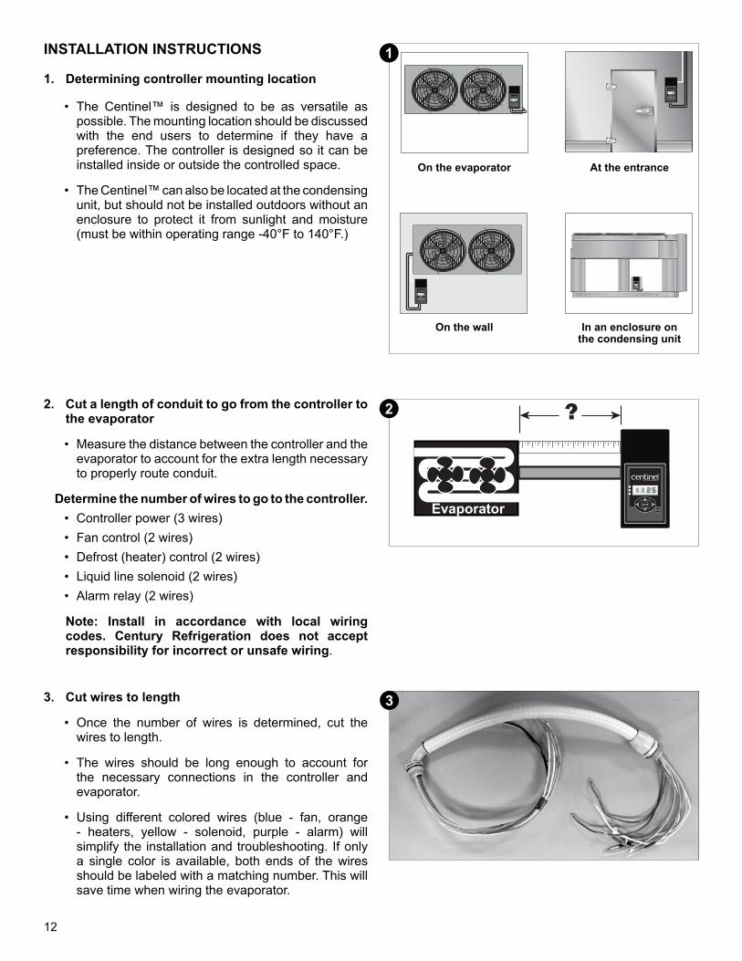
1. Determining controller mounting location
• The Centinel™ is designed to be as versatile as possible. The mounting location should be discussed with the end users to determine if they have a preference. The controller is designed so it can be installed inside or outside the controlled space.
• The Centinel™ can also be located at the condensing unit, but should not be installed outdoors without an enclosure to protect it from sunlight and moisture (must be within operating range -40°F to 140°F.)
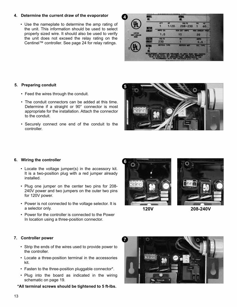
2. Cut a length of conduit to go from the controller to the evaporator
• Measure the distance between the controller and the evaporator to account for the extra length necessary to properly route conduit.
Determine the number of wires to go to the controller.• Controller power (3 wires)• Fan control (2 wires)• Defrost (heater) control (2 wires)• Liquid line solenoid (2 wires)• Alarm relay (2 wires)
Note: Install in accordance with local wiring codes. Century Refrigeration does not accept responsibility for incorrect or unsafe wiring.
Evaporator
?
2222
ENTER
BACK
by Century Refrigeration
22
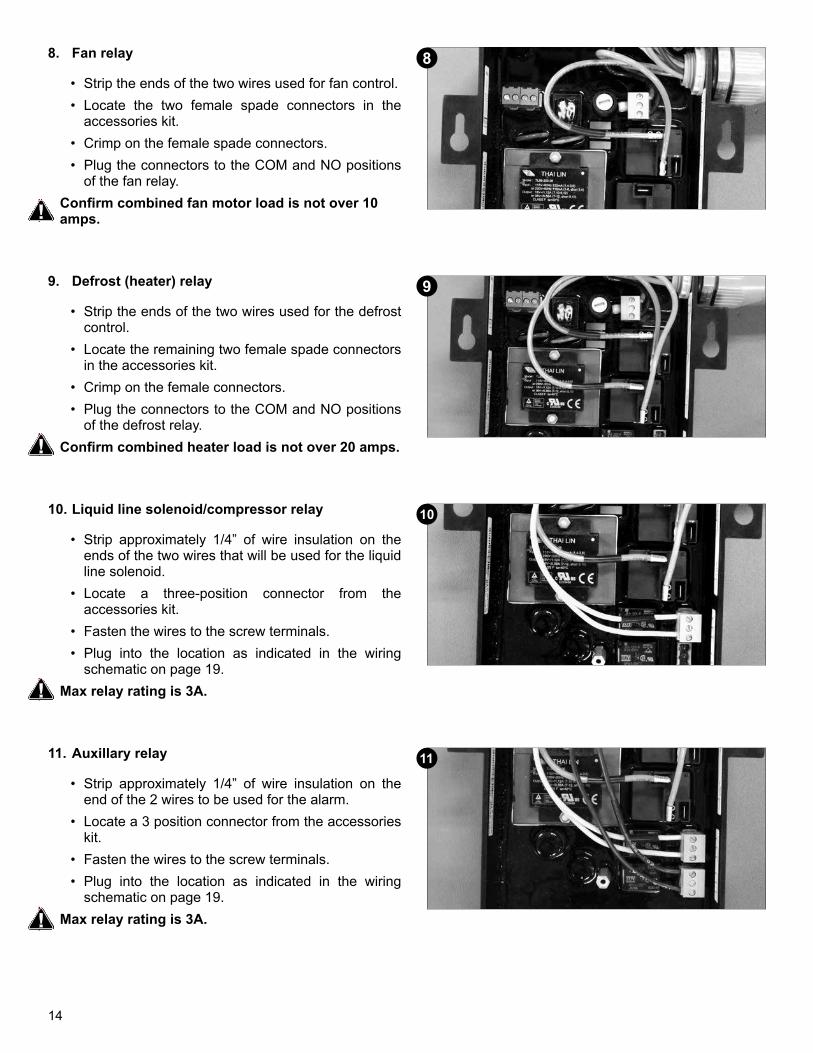
3. Cut wires to length
• Once the number of wires is determined, cut the wires to length.
• The wires should be long enough to account for the necessary connections in the controller and evaporator.
• Using different colored wires (blue - fan, orange - heaters, yellow - solenoid, purple - alarm) will simplify the installation and troubleshooting. If only a single color is available, both ends of the wires should be labeled with a matching number. This will save time when wiring the evaporator.
2222
ENTER
BACK
by Century Refrigeration
22
2222
ENTER
BACK
by Century Refrigeration
22
2222
ENTER
BACK
by Century Refrigeration
22
2222
ENTER
BACK
by Century Refrigeration
22
On the evaporator At the entrance
On the wall In an enclosure on the condensing unit
1
2
3
13
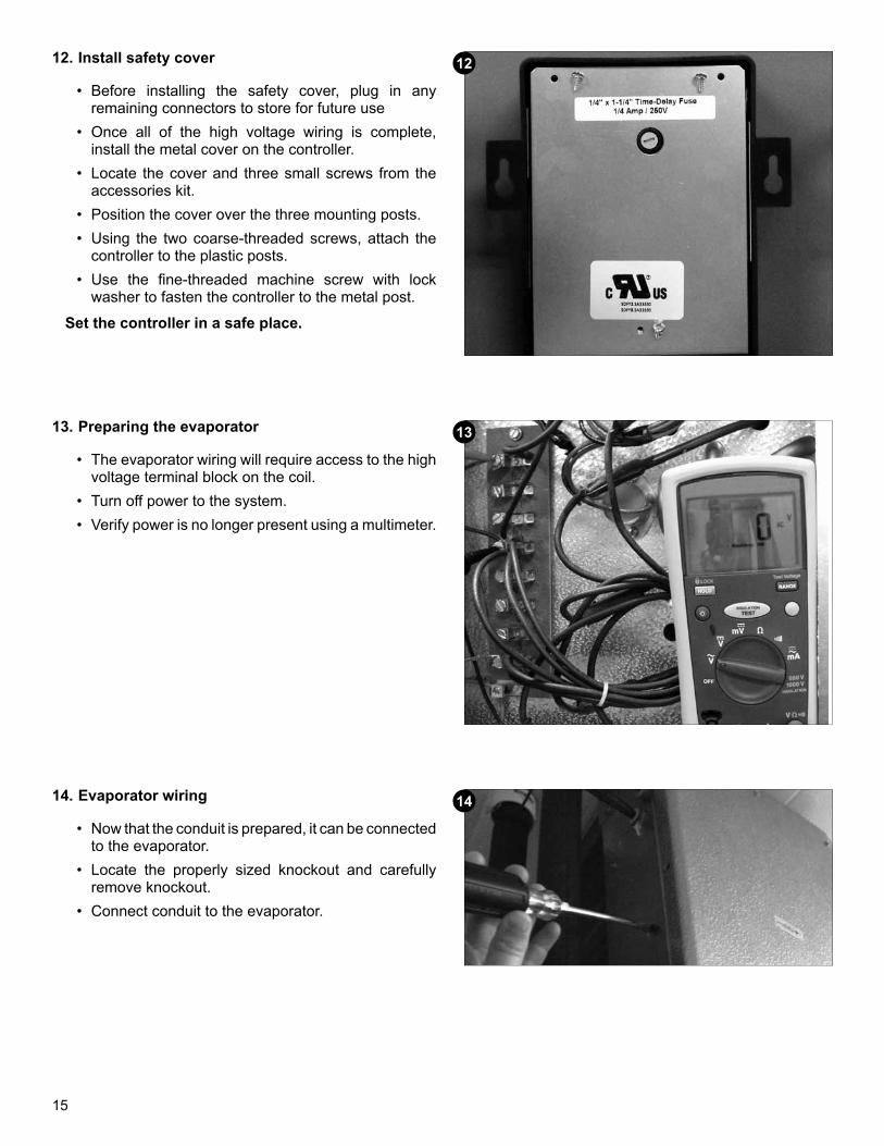
4. Determine the current draw of the evaporator
• Use the nameplate to determine the amp rating of the unit. This information should be used to select properly sized wire. It should also be used to verify the unit does not exceed the relay rating on the Centinel™ controller. See page 24 for relay ratings.
4
5. Preparing conduit
• Feed the wires through the conduit.
• The conduit connectors can be added at this time. Determine if a straight or 90° connector is most appropriate for the installation. Attach the connector to the conduit.
• Securely connect one end of the conduit to the controller.
5
6. Wiring the controller
• Locate the voltage jumper(s) in the accessory kit. It is a two-position plug with a red jumper already installed.
• Plug one jumper on the center two pins for 208-240V power and two jumpers on the outer two pins for 120V power.
• Power is not connected to the voltage selector. It is a selector only.
• Power for the controller is connected to the Power In location using a three-position connector.
120V 208-240V
6
7. Controller power
• Strip the ends of the wires used to provide power to the controller.
• Locate a three-position terminal in the accessories kit.
• Fasten to the three-position pluggable connector*. • Plug into the board as indicated in the wiring
schematic on page 19.*All terminal screws should be tightened to 5 ft-lbs.
7
14
8. Fan relay
• Strip the ends of the two wires used for fan control.• Locate the two female spade connectors in the
accessories kit.• Crimp on the female spade connectors. • Plug the connectors to the COM and NO positions
of the fan relay. Confirm combined fan motor load is not over 10 amps.
8
9. Defrost (heater) relay
• Strip the ends of the two wires used for the defrost control.
• Locate the remaining two female spade connectors in the accessories kit.
• Crimp on the female connectors.• Plug the connectors to the COM and NO positions
of the defrost relay. Confirm combined heater load is not over 20 amps.
9
10. Liquid line solenoid/compressor relay
• Strip approximately 1/4” of wire insulation on the ends of the two wires that will be used for the liquid line solenoid.
• Locate a three-position connector from the accessories kit.
• Fasten the wires to the screw terminals.• Plug into the location as indicated in the wiring
schematic on page 19.Max relay rating is 3A.
10
11. Auxillary relay
• Strip approximately 1/4” of wire insulation on the end of the 2 wires to be used for the alarm.
• Locate a 3 position connector from the accessories kit.
• Fasten the wires to the screw terminals.• Plug into the location as indicated in the wiring
schematic on page 19.Max relay rating is 3A.
11
15
12. Install safety cover
• Before installing the safety cover, plug in any remaining connectors to store for future use
• Once all of the high voltage wiring is complete, install the metal cover on the controller.
• Locate the cover and three small screws from the accessories kit.
• Position the cover over the three mounting posts.• Using the two coarse-threaded screws, attach the
controller to the plastic posts.• Use the fine-threaded machine screw with lock
washer to fasten the controller to the metal post.
Set the controller in a safe place.
12
13. Preparing the evaporator
• The evaporator wiring will require access to the high voltage terminal block on the coil.
• Turn off power to the system.• Verify power is no longer present using a multimeter.
13
14. Evaporator wiring
• Now that the conduit is prepared, it can be connected to the evaporator.
• Locate the properly sized knockout and carefully remove knockout.
• Connect conduit to the evaporator.
14
16
15. Study the existing wiring
• Determine the location of the following: incoming power, fan leads, heater leads, defrost termination leads, and fan delay leads.
• Controller can be wired as load duty (see page 24 for relay ratings) or the relay outputs can be used to energize contactors (see page 19 for typical wiring.)
16. Evaporator wiring - controller
• Strip the ends of the wires used to power the controller.• Attach to the line power to provide continuous power to the controller.• Attach ground wire.
Note: Ground is required for the internal safeties to operate properly.
17. Fan relay wiring
• Strip the ends of the wires (connected to the Centinel™) used to control the evaporator fans. • Attach a wire on the fan relay common to L1/Line voltage.• Attach the wire connected to the NO terminal on the fan relay to one of the fan motor or contactor leads.• Connect L2/Neutral to remaining fan motor or contactor lead.
18. Heater relay wiring
• Strip the ends of the wires being used for heater control.• Attach a wire on the heater relay common to L1/Line voltage.• The heater wires can be attached to the terminal block using either screw down terminals or spade connectors.
19. Remove defrost termination from circuitry
• Attach the wire connected to the NO terminal on the defrost relay to one of the defrost or contactor coil leads.• Connect L2/Neutral to the remaining defrost or contactor coil leads.
The defrost safety should not be removed from the circuit. Its purpose is to prevent the heaters from over heating and causing damage.
20. Evaporator wiring - liquid line solenoid/compressor
• Strip the ends of the wires selected to control the liquid line solenoid.• Attach the wire from the NO terminal on the liquid line solenoid/compressor relay to one of the solenoid leads.
Attach the wire from the COM on the liquid line solenoid/compressor relay to the L1/Line Voltage.• Connect L2/Neutral to the remaining liquid line solenoid/compressor lead.
17
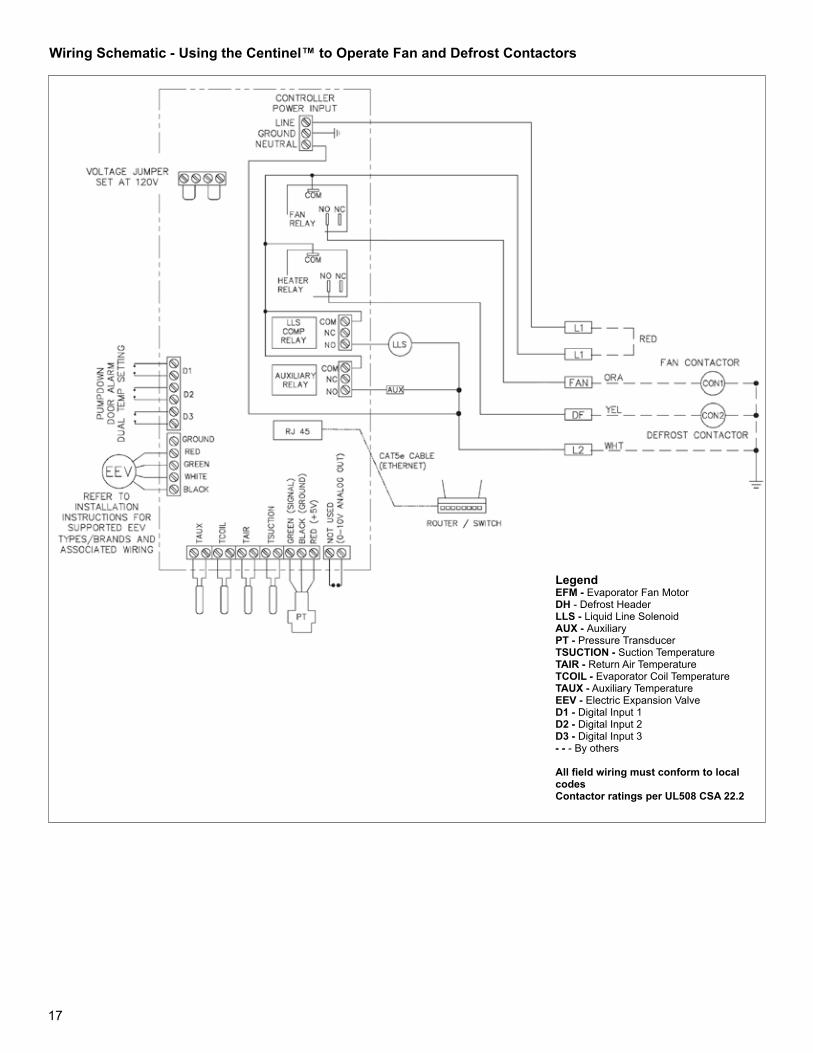
Wiring Schematic - Using the Centinel™ to Operate Fan and Defrost Contactors
LegendEFM - Evaporator Fan MotorDH - Defrost HeaderLLS - Liquid Line SolenoidAUX - AuxiliaryPT - Pressure TransducerTSUCTION - Suction TemperatureTAIR - Return Air TemperatureTCOIL - Evaporator Coil TemperatureTAUX - Auxiliary TemperatureEEV - Electric Expansion ValveD1 - Digital Input 1D2 - Digital Input 2D3 - Digital Input 3- - - By others
All field wiring must conform to local codesContactor ratings per UL508 CSA 22.2
18
21. Auxiliary relay wiring
• Century Refrigeration uses the auxiliary temperature input as a second coil temperature input as standard. Using the auxiliary for alternative inputs is not recommended and the factory should be consulted for other uses.
• Depending on auxiliary relay location, an additional conduit may be required.
• Strip the ends selected to control the auxiliary component.
• Break the hot leg of the auxiliary component.• Attach the wire from the NO terminal on the auxiliary
relay to one of the auxiliary component leads. Attach the wire from the COM on the auxiliary component relay to the L1/Line Voltage.
• Connect L2/Neutral to the remaining auxiliary component lead.
• Route and secure the conduit to the location the controller is to be installed.
• Wiring must follow local wiring codes.
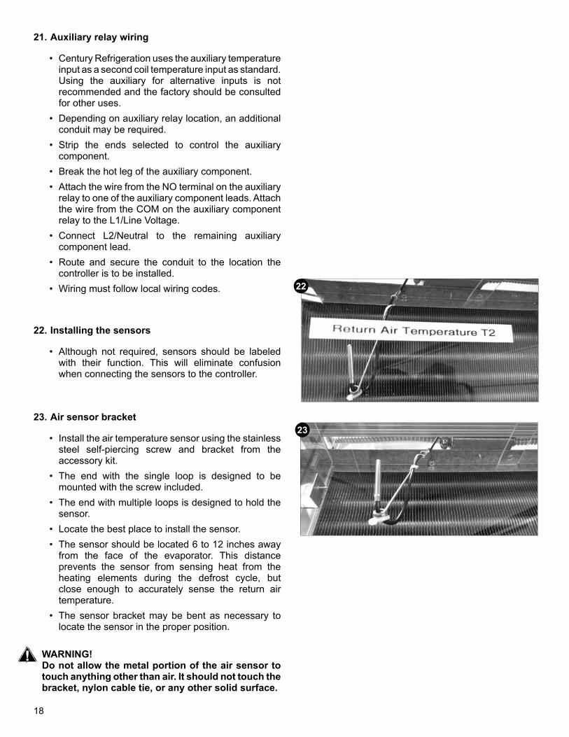
22. Installing the sensors
• Although not required, sensors should be labeled with their function. This will eliminate confusion when connecting the sensors to the controller.
23. Air sensor bracket
• Install the air temperature sensor using the stainless steel self-piercing screw and bracket from the accessory kit.
• The end with the single loop is designed to be mounted with the screw included.
• The end with multiple loops is designed to hold the sensor.
• Locate the best place to install the sensor. • The sensor should be located 6 to 12 inches away
from the face of the evaporator. This distance prevents the sensor from sensing heat from the heating elements during the defrost cycle, but close enough to accurately sense the return air temperature.
• The sensor bracket may be bent as necessary to locate the sensor in the proper position.
WARNING!Do not allow the metal portion of the air sensor to touch anything other than air. It should not touch the bracket, nylon cable tie, or any other solid surface.
22
23
19
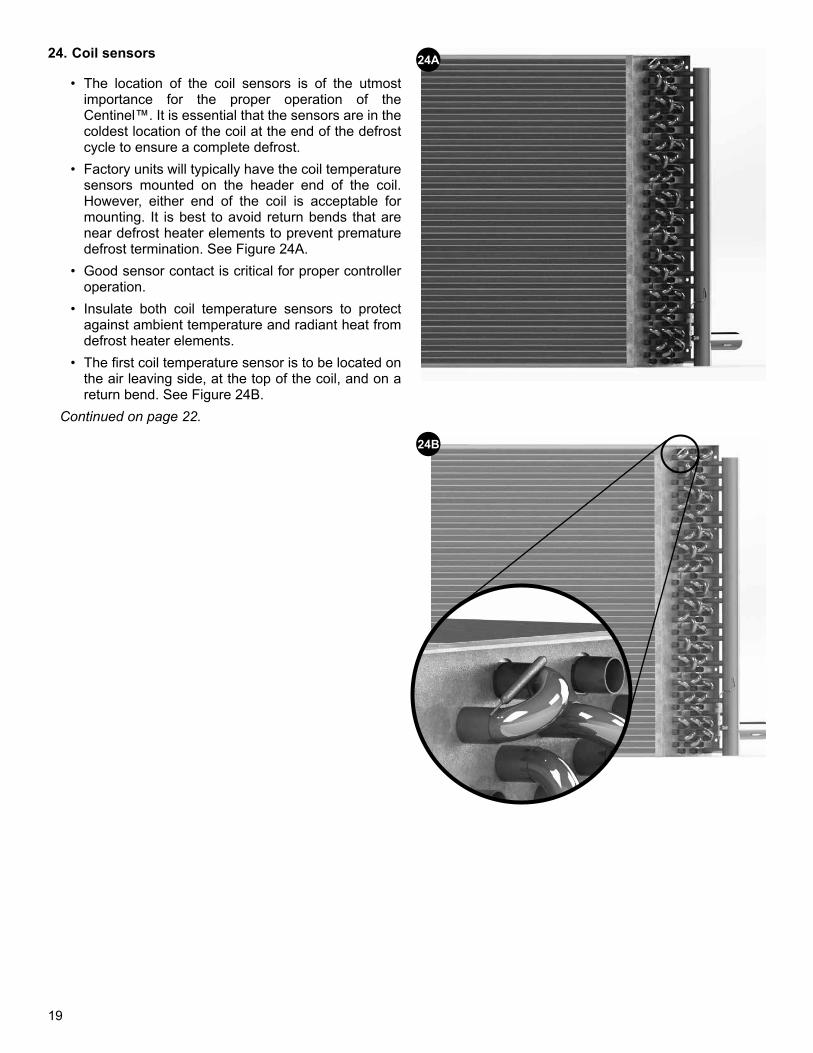
24. Coil sensors
• The location of the coil sensors is of the utmost importance for the proper operation of the Centinel™. It is essential that the sensors are in the coldest location of the coil at the end of the defrost cycle to ensure a complete defrost.
• Factory units will typically have the coil temperature sensors mounted on the header end of the coil. However, either end of the coil is acceptable for mounting. It is best to avoid return bends that are near defrost heater elements to prevent premature defrost termination. See Figure 24A.
• Good sensor contact is critical for proper controller operation.
• Insulate both coil temperature sensors to protect against ambient temperature and radiant heat from defrost heater elements.
• The first coil temperature sensor is to be located on the air leaving side, at the top of the coil, and on a return bend. See Figure 24B.
Continued on page 22.
24A
24B
20
Extending sensor wires
• After the sensors are mounted, they are routed back to the controller. If the sensors are mounted within 40 feet of the controller, the included wiring may be used without modification. If the installation requires more than 40 feet, the wires must be extended using 18 gauge twisted shielded pair. Maximum length for 18 gauge is 300 ft.
• Soldering wires is the required method for extending wire length. This ensures the best connection for reliability and a quality signal.
• When running the wires back to the controller care must be taken to avoid interference with the sensor wires. Interference can be introduced when sensor wires are located near high voltage lines. High voltage is defined by United Laboratories as above 30 volts . The higher the voltage, the more likely it is to introduce interference and the more important it is to avoid.
• If crossing a high voltage line is necessary, the sensor wiring should be run at right angles to prevent noise.
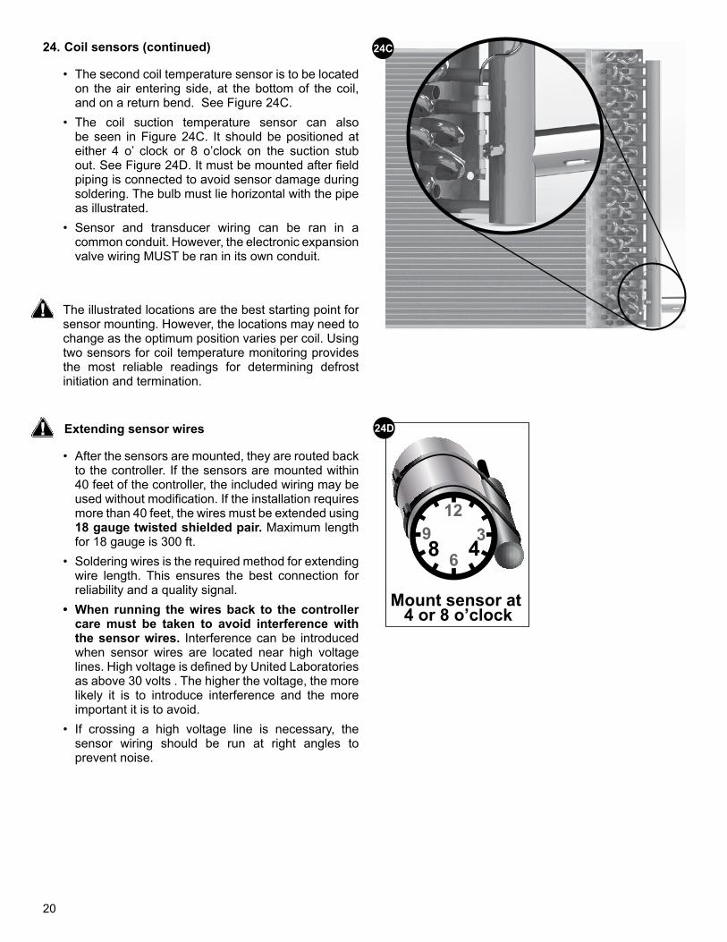
24C24. Coil sensors (continued)
• The second coil temperature sensor is to be located on the air entering side, at the bottom of the coil, and on a return bend. See Figure 24C.
• The coil suction temperature sensor can also be seen in Figure 24C. It should be positioned at either 4 o’ clock or 8 o’clock on the suction stub out. See Figure 24D. It must be mounted after field piping is connected to avoid sensor damage during soldering. The bulb must lie horizontal with the pipe as illustrated.
• Sensor and transducer wiring can be ran in a common conduit. However, the electronic expansion valve wiring MUST be ran in its own conduit.
The illustrated locations are the best starting point for sensor mounting. However, the locations may need to change as the optimum position varies per coil. Using two sensors for coil temperature monitoring provides the most reliable readings for determining defrost initiation and termination.
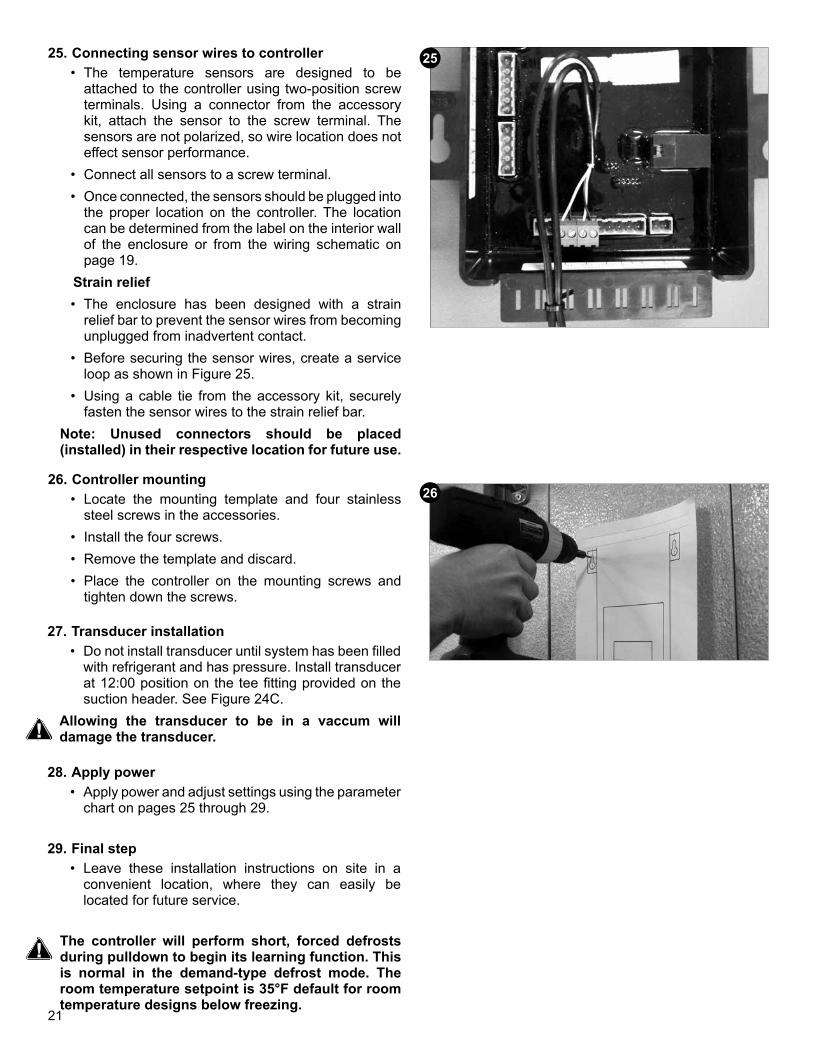
Mount sensor at 4 or 8 o’clock
12
69 3
48
24D
21
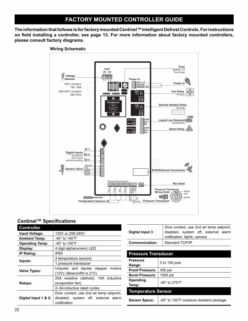
25. Connecting sensor wires to controller• The temperature sensors are designed to be
attached to the controller using two-position screw terminals. Using a connector from the accessory kit, attach the sensor to the screw terminal. The sensors are not polarized, so wire location does not effect sensor performance.
• Connect all sensors to a screw terminal.• Once connected, the sensors should be plugged into
the proper location on the controller. The location can be determined from the label on the interior wall of the enclosure or from the wiring schematic on page 19.
Strain relief• The enclosure has been designed with a strain
relief bar to prevent the sensor wires from becoming unplugged from inadvertent contact.
• Before securing the sensor wires, create a service loop as shown in Figure 25.
• Using a cable tie from the accessory kit, securely fasten the sensor wires to the strain relief bar.
Note: Unused connectors should be placed (installed) in their respective location for future use.
25
26. Controller mounting• Locate the mounting template and four stainless
steel screws in the accessories.• Install the four screws.• Remove the template and discard.• Place the controller on the mounting screws and
tighten down the screws.
27. Transducer installation• Do not install transducer until system has been filled
with refrigerant and has pressure. Install transducer at 12:00 position on the tee fitting provided on the suction header. See Figure 24C.
Allowing the transducer to be in a vaccum will damage the transducer.
26
29. Final step• Leave these installation instructions on site in a
convenient location, where they can easily be located for future service.
28. Apply power• Apply power and adjust settings using the parameter
chart on pages 25 through 29.
The controller will perform short, forced defrosts during pulldown to begin its learning function. This is normal in the demand-type defrost mode. The room temperature setpoint is 35°F default for room temperature designs below freezing.
22
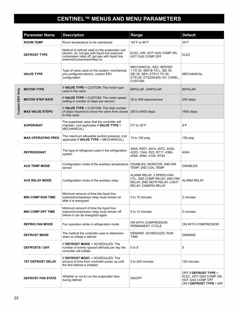
FACTORY MOUNTED CONTROLLER GUIDEThe information that follows is for factory mounted Centinel™ Intelligent Defrost Controls. For instructions on field installing a controller, see page 13. For more information about factory mounted controllers, please consult factory diagrams.
Centinel™ SpecificationsControllerInput Voltage: 120V or 208-240VAmbient Temp: -40° to 140°FOperating Temp: -40° to 140°FDisplay: 4 digit alphanumeric LEDIP Rating: IP65
Inputs: 4 temperature sensors1 pressure transducer
Valve Types: Unipolar and bipolar stepper motors (12V); (Beacon®II is 21V)
Relays:20A resistive (defrost); 10A inductive (evaporator fan)2–3A inductive rated cycles
Digital Input 1 & 2:Door contact, use 2nd air temp setpoint, disabled, system off, external alarm notification
Digital Input 3Door contact, use 2nd air temp setpoint, disabled, system off, external alarm notification, lights, camera
Communication: Standard TCP/IP
Pressure TransducerPressure Range: 0 to 150 psia
Proof Pressure: 450 psiBurst Pressure: 1500 psiOperating Temp: -40° to 275°F
Temperature Sensor
Sensor Specs: -60° to 150°F moisture resistant package
208-240120120
Temperature Sensors
TSuc
t
TAux
TAir
TCoi
l
line / L1 groundneutral / L2
NCNO
NO NC
NO NC
COM
COM
NC
Power In
gree
n
red
blac
k
NO
Transformer
3A Relay
3A Relay COM
COM
COMNCNO
COMNCNO
18V
DI 1
DI 3
DI 2
Electric Valve*
Temperature Sensors (4) Pressure Transducer
RJ45 Ethernet Connection
Not Used
Fuse
groundredgreenwhiteblack
Alarm Relay
Fan Relay (10 amp)
groundsign
al
+5
Defrost (Heater) Relay(20 amp)
Bk/MDL-1/4Time Delay
Liquid Line Solenoid
Power In
(compressor)
door switchdual temp setting
pumpdownDigital Inputs
Pressure Transducer Wiring Detail black
redgreen
VoltageSelector 1 2 3 4
120V Jumpers1&2, 3&4
208-240V Jumpers2&3 Only
Wiring Schematic
23
CENTINEL™ MENUS AND MENU PARAMETERS
Parameter Name Description Range Default
ROOM TEMP Room temperature to be maintained -50°F to 90°F 35°F
DEFROST TYPEMethod of defrost used on the evaporator coil: electric, air, hot gas with liquid line solenoid/compressor relay off, got gas with liquid line solenoid/compressorrelay on
ELEC, AIR, HOT GAS COMP ON, HOT GAS COMP OFF ELEC
VALVE TYPEType of valve used on the system: mechanical, pre-configured electric, custom EEV configuration
MECHANICAL, KE2, SER/SEI 1 TO 20, SER B TO L, SEI 30, SEI 50, SEH, ETS12 TO 50, ETS100, ETS250/400, KV, CAREL, CUSTOM;
MECHANICAL
Cus
tom
EEV
Onl
y MOTOR TYPE If VALVE TYPE = CUSTOM: The motor type used in the valve BIPOLAR, UNIPOLAR BIPOLAR
MOTOR STEP RATE If VALVE TYPE = CUSTOM: The motor speed setting in number of steps per second 30 to 400 steps/second 200 steps
MAX VALVE STEPSIf VALVE TYPE = CUSTOM: The total number of steps required to move the valve from closed to fully open
200 to 6400 steps 1600 steps
SUPERHEATThe superheat value that the controller will maintain, (not applicable if VALVE TYPE = MECHANICAL)
5°F to 30°F 8°F
MAX OPERATING PRES The maximum allowable suction pressure, (not applicable if VALVE TYPE = MECHANICAL) 10 to 150 psig 150 psig
REFRIGERANT The type of refrigerant used in the refrigeration system
404A, R507, 407A, 407C, 422A, 422D, 134A, R22, R717, 438A, 408A, 409A, 410A, R744
404A
AUX TEMP MODE Configuration mode of the auxiliary temperature sensor
DISABLED, MONITOR, 2ND AIR TEMP, 2ND COIL TEMP DISABLED
AUX RELAY MODE Configuration mode of the auxiliary relay.
ALARM RELAY, 2 SPEED FAN CTL, 2ND COMP RELAY, 2ND FAN RELAY, 2ND DEFR RELAY, LIGHT RELAY, CAMERA RELAY
ALARM RELAY
MIN COMP RUN TIMEMinimum amount of time the liquid line solenoid/compressor relay must remain on after it is energized
0 to 15 minutes 2 minutes
MIN COMP OFF TIMEMinimum amount of time the liquid line solenoid/compressor relay must remain off before it can be energized again.
0 to 15 minutes 5 minutes
REFRIG FAN MODE Fan operation while in refrigeration mode ON WITH COMPRESSOR, PERMANENT, CYCLE ON WITH COMPRESSOR
DEFROST MODE The method the controller uses to determine when to initiate a defrost
DEMAND, SCHEDULED, RUN TIME DEMAND
DEFROSTS / DAYIf DEFROST MODE = SCHEDULED: The number of evenly spaced defrosts per day the controller will initiate
0 to 8 5
1ST DEFROST DELAYIf DEFROST MODE = SCHEDULED: The amount of time from controller power up until the first defrost is initiated
0 to 240 minutes 120 minutes
DEFROST FAN STATE Whether or not to run the evaporator fans during defrost ON/OFF
OFF if DEFROST TYPE = ELEC, HOT GAS COMP ON, HOT GAS COMP OFFON if DEFROST TYPE = AIR
24
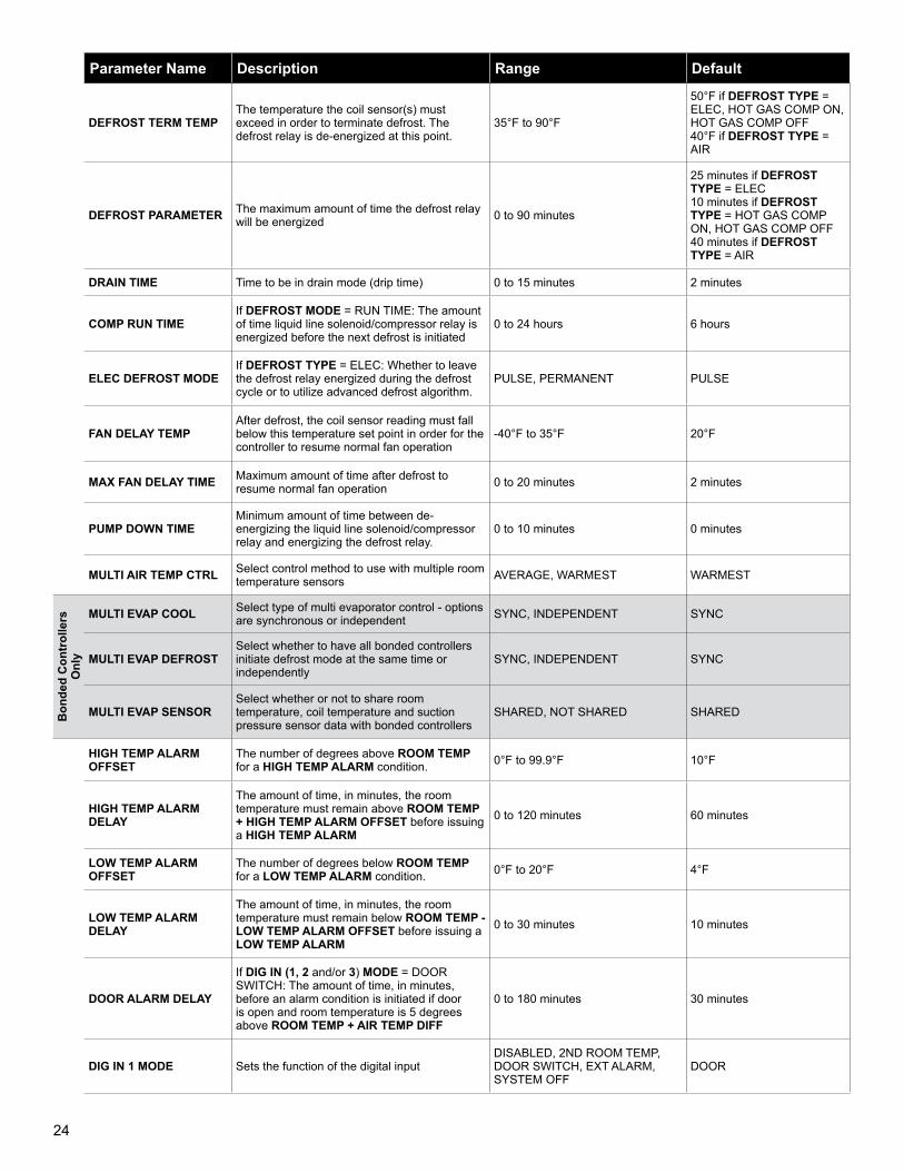
Parameter Name Description Range Default
DEFROST TERM TEMPThe temperature the coil sensor(s) must exceed in order to terminate defrost. The defrost relay is de-energized at this point.
35°F to 90°F
50°F if DEFROST TYPE = ELEC, HOT GAS COMP ON, HOT GAS COMP OFF40°F if DEFROST TYPE = AIR
DEFROST PARAMETER The maximum amount of time the defrost relay will be energized 0 to 90 minutes
25 minutes if DEFROST TYPE = ELEC10 minutes if DEFROST TYPE = HOT GAS COMP ON, HOT GAS COMP OFF40 minutes if DEFROST TYPE = AIR
DRAIN TIME Time to be in drain mode (drip time) 0 to 15 minutes 2 minutes
COMP RUN TIMEIf DEFROST MODE = RUN TIME: The amount of time liquid line solenoid/compressor relay is energized before the next defrost is initiated
0 to 24 hours 6 hours
ELEC DEFROST MODEIf DEFROST TYPE = ELEC: Whether to leave the defrost relay energized during the defrost cycle or to utilize advanced defrost algorithm.
PULSE, PERMANENT PULSE
FAN DELAY TEMPAfter defrost, the coil sensor reading must fall below this temperature set point in order for the controller to resume normal fan operation
-40°F to 35°F 20°F
MAX FAN DELAY TIME Maximum amount of time after defrost to resume normal fan operation 0 to 20 minutes 2 minutes
PUMP DOWN TIMEMinimum amount of time between de-energizing the liquid line solenoid/compressor relay and energizing the defrost relay.
0 to 10 minutes 0 minutes
MULTI AIR TEMP CTRL Select control method to use with multiple room temperature sensors AVERAGE, WARMEST WARMEST
Bon
ded
Con
trol
lers
O
nly
MULTI EVAP COOL Select type of multi evaporator control - options are synchronous or independent SYNC, INDEPENDENT SYNC
MULTI EVAP DEFROSTSelect whether to have all bonded controllers initiate defrost mode at the same time or independently
SYNC, INDEPENDENT SYNC
MULTI EVAP SENSORSelect whether or not to share room temperature, coil temperature and suction pressure sensor data with bonded controllers
SHARED, NOT SHARED SHARED
HIGH TEMP ALARM OFFSET
The number of degrees above ROOM TEMP for a HIGH TEMP ALARM condition. 0°F to 99.9°F 10°F
HIGH TEMP ALARM DELAY
The amount of time, in minutes, the room temperature must remain above ROOM TEMP + HIGH TEMP ALARM OFFSET before issuing a HIGH TEMP ALARM
0 to 120 minutes 60 minutes
LOW TEMP ALARM OFFSET
The number of degrees below ROOM TEMP for a LOW TEMP ALARM condition. 0°F to 20°F 4°F
LOW TEMP ALARM DELAY
The amount of time, in minutes, the room temperature must remain below ROOM TEMP - LOW TEMP ALARM OFFSET before issuing a LOW TEMP ALARM
0 to 30 minutes 10 minutes
DOOR ALARM DELAY
If DIG IN (1, 2 and/or 3) MODE = DOOR SWITCH: The amount of time, in minutes, before an alarm condition is initiated if door is open and room temperature is 5 degrees above ROOM TEMP + AIR TEMP DIFF
0 to 180 minutes 30 minutes
DIG IN 1 MODE Sets the function of the digital inputDISABLED, 2ND ROOM TEMP, DOOR SWITCH, EXT ALARM, SYSTEM OFF
DOOR
25
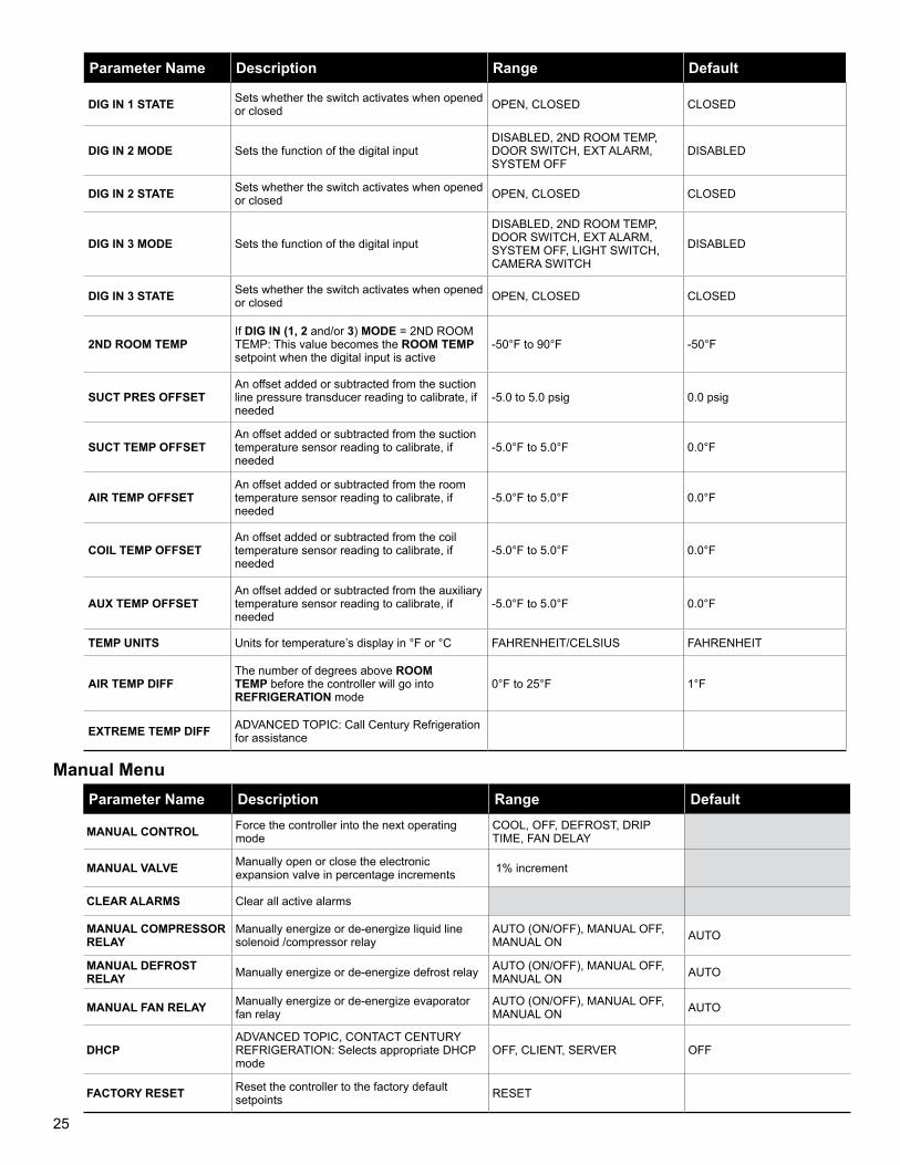
Parameter Name Description Range Default
DIG IN 1 STATE Sets whether the switch activates when opened or closed OPEN, CLOSED CLOSED
DIG IN 2 MODE Sets the function of the digital inputDISABLED, 2ND ROOM TEMP, DOOR SWITCH, EXT ALARM, SYSTEM OFF
DISABLED
DIG IN 2 STATE Sets whether the switch activates when opened or closed OPEN, CLOSED CLOSED
DIG IN 3 MODE Sets the function of the digital input
DISABLED, 2ND ROOM TEMP, DOOR SWITCH, EXT ALARM, SYSTEM OFF, LIGHT SWITCH, CAMERA SWITCH
DISABLED
DIG IN 3 STATE Sets whether the switch activates when opened or closed OPEN, CLOSED CLOSED
2ND ROOM TEMPIf DIG IN (1, 2 and/or 3) MODE = 2ND ROOM TEMP: This value becomes the ROOM TEMP setpoint when the digital input is active
-50°F to 90°F -50°F
SUCT PRES OFFSETAn offset added or subtracted from the suction line pressure transducer reading to calibrate, if needed
-5.0 to 5.0 psig 0.0 psig
SUCT TEMP OFFSETAn offset added or subtracted from the suction temperature sensor reading to calibrate, if needed
-5.0°F to 5.0°F 0.0°F
AIR TEMP OFFSETAn offset added or subtracted from the room temperature sensor reading to calibrate, if needed
-5.0°F to 5.0°F 0.0°F
COIL TEMP OFFSETAn offset added or subtracted from the coil temperature sensor reading to calibrate, if needed
-5.0°F to 5.0°F 0.0°F
AUX TEMP OFFSETAn offset added or subtracted from the auxiliary temperature sensor reading to calibrate, if needed
-5.0°F to 5.0°F 0.0°F
TEMP UNITS Units for temperature’s display in °F or °C FAHRENHEIT/CELSIUS FAHRENHEIT
AIR TEMP DIFFThe number of degrees above ROOM TEMP before the controller will go into REFRIGERATION mode
0°F to 25°F 1°F
EXTREME TEMP DIFF ADVANCED TOPIC: Call Century Refrigeration for assistance
Parameter Name Description Range Default
MANUAL CONTROL Force the controller into the next operating mode
COOL, OFF, DEFROST, DRIP TIME, FAN DELAY
MANUAL VALVE Manually open or close the electronic expansion valve in percentage increments 1% increment
CLEAR ALARMS Clear all active alarms
MANUAL COMPRESSOR RELAY
Manually energize or de-energize liquid line solenoid /compressor relay
AUTO (ON/OFF), MANUAL OFF, MANUAL ON AUTO
MANUAL DEFROST RELAY Manually energize or de-energize defrost relay AUTO (ON/OFF), MANUAL OFF,
MANUAL ON AUTO
MANUAL FAN RELAY Manually energize or de-energize evaporator fan relay
AUTO (ON/OFF), MANUAL OFF, MANUAL ON AUTO
DHCPADVANCED TOPIC, CONTACT CENTURY REFRIGERATION: Selects appropriate DHCP mode
OFF, CLIENT, SERVER OFF
FACTORY RESET Reset the controller to the factory default setpoints RESET
Manual Menu
26
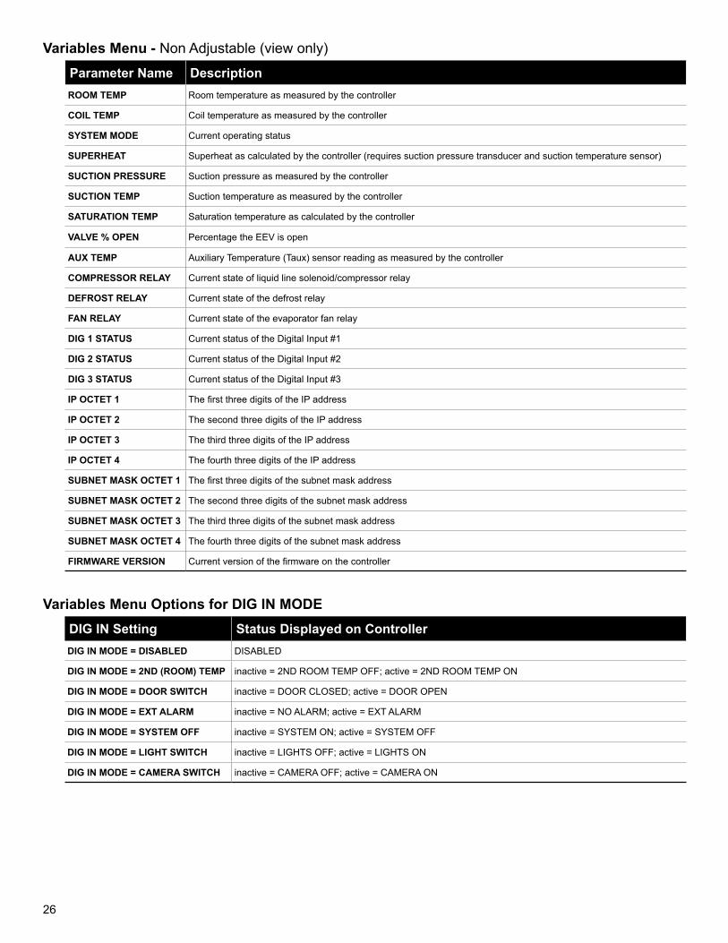
Parameter Name DescriptionROOM TEMP Room temperature as measured by the controller
COIL TEMP Coil temperature as measured by the controller
SYSTEM MODE Current operating status
SUPERHEAT Superheat as calculated by the controller (requires suction pressure transducer and suction temperature sensor)
SUCTION PRESSURE Suction pressure as measured by the controller
SUCTION TEMP Suction temperature as measured by the controller
SATURATION TEMP Saturation temperature as calculated by the controller
VALVE % OPEN Percentage the EEV is open
AUX TEMP Auxiliary Temperature (Taux) sensor reading as measured by the controller
COMPRESSOR RELAY Current state of liquid line solenoid/compressor relay
DEFROST RELAY Current state of the defrost relay
FAN RELAY Current state of the evaporator fan relay
DIG 1 STATUS Current status of the Digital Input #1
DIG 2 STATUS Current status of the Digital Input #2
DIG 3 STATUS Current status of the Digital Input #3
IP OCTET 1 The first three digits of the IP address
IP OCTET 2 The second three digits of the IP address
IP OCTET 3 The third three digits of the IP address
IP OCTET 4 The fourth three digits of the IP address
SUBNET MASK OCTET 1 The first three digits of the subnet mask address
SUBNET MASK OCTET 2 The second three digits of the subnet mask address
SUBNET MASK OCTET 3 The third three digits of the subnet mask address
SUBNET MASK OCTET 4 The fourth three digits of the subnet mask address
FIRMWARE VERSION Current version of the firmware on the controller
Variables Menu - Non Adjustable (view only)
DIG IN Setting Status Displayed on ControllerDIG IN MODE = DISABLED DISABLED
DIG IN MODE = 2ND (ROOM) TEMP inactive = 2ND ROOM TEMP OFF; active = 2ND ROOM TEMP ON
DIG IN MODE = DOOR SWITCH inactive = DOOR CLOSED; active = DOOR OPEN
DIG IN MODE = EXT ALARM inactive = NO ALARM; active = EXT ALARM
DIG IN MODE = SYSTEM OFF inactive = SYSTEM ON; active = SYSTEM OFF
DIG IN MODE = LIGHT SWITCH inactive = LIGHTS OFF; active = LIGHTS ON
DIG IN MODE = CAMERA SWITCH inactive = CAMERA OFF; active = CAMERA ON
Variables Menu Options for DIG IN MODE
27
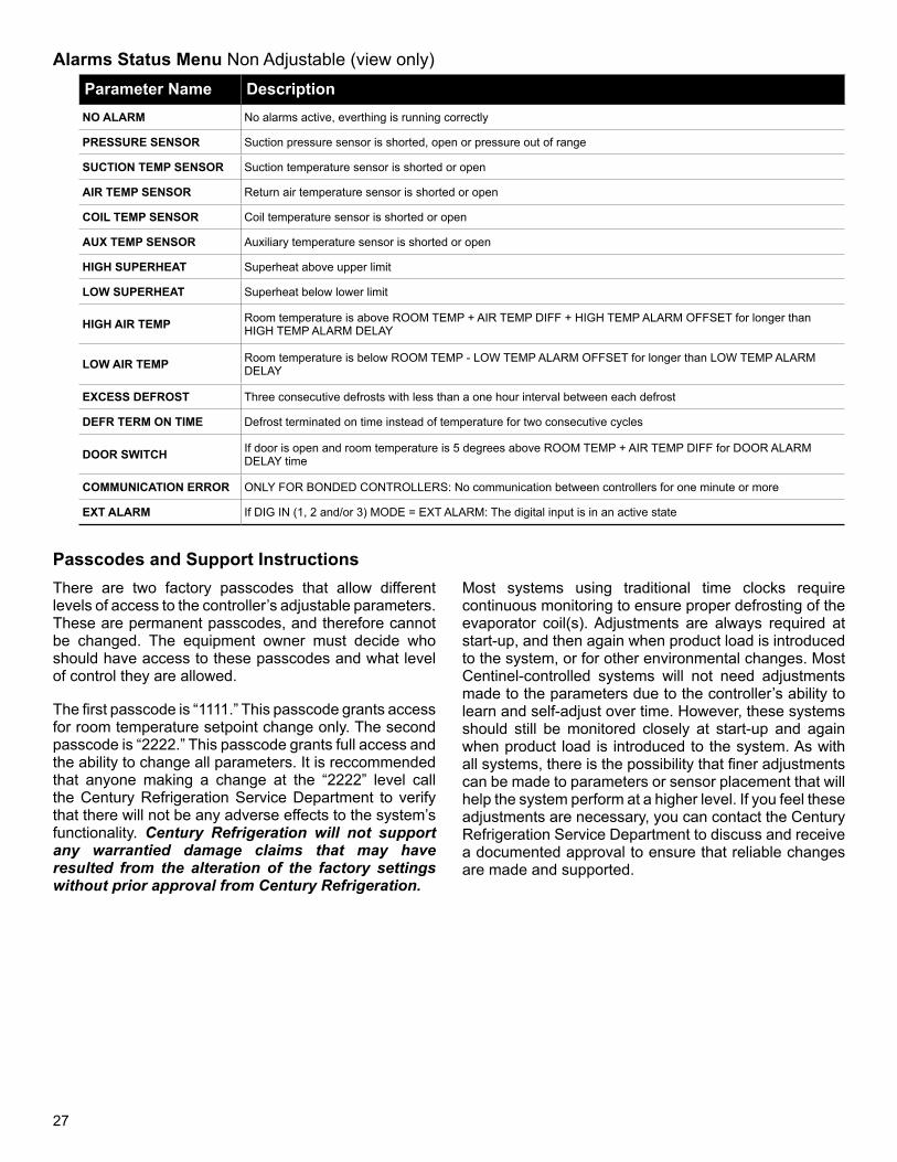
There are two factory passcodes that allow different levels of access to the controller’s adjustable parameters. These are permanent passcodes, and therefore cannot be changed. The equipment owner must decide who should have access to these passcodes and what level of control they are allowed.
The first passcode is “1111.” This passcode grants access for room temperature setpoint change only. The second passcode is “2222.” This passcode grants full access and the ability to change all parameters. It is reccommended that anyone making a change at the “2222” level call the Century Refrigeration Service Department to verify that there will not be any adverse effects to the system’s functionality. Century Refrigeration will not support any warrantied damage claims that may have resulted from the alteration of the factory settings without prior approval from Century Refrigeration.
Most systems using traditional time clocks require continuous monitoring to ensure proper defrosting of the evaporator coil(s). Adjustments are always required at start-up, and then again when product load is introduced to the system, or for other environmental changes. Most Centinel-controlled systems will not need adjustments made to the parameters due to the controller’s ability to learn and self-adjust over time. However, these systems should still be monitored closely at start-up and again when product load is introduced to the system. As with all systems, there is the possibility that finer adjustments can be made to parameters or sensor placement that will help the system perform at a higher level. If you feel these adjustments are necessary, you can contact the Century Refrigeration Service Department to discuss and receive a documented approval to ensure that reliable changes are made and supported.
Parameter Name DescriptionNO ALARM No alarms active, everthing is running correctly
PRESSURE SENSOR Suction pressure sensor is shorted, open or pressure out of range
SUCTION TEMP SENSOR Suction temperature sensor is shorted or open
AIR TEMP SENSOR Return air temperature sensor is shorted or open
COIL TEMP SENSOR Coil temperature sensor is shorted or open
AUX TEMP SENSOR Auxiliary temperature sensor is shorted or open
HIGH SUPERHEAT Superheat above upper limit
LOW SUPERHEAT Superheat below lower limit
HIGH AIR TEMP Room temperature is above ROOM TEMP + AIR TEMP DIFF + HIGH TEMP ALARM OFFSET for longer than HIGH TEMP ALARM DELAY
LOW AIR TEMP Room temperature is below ROOM TEMP - LOW TEMP ALARM OFFSET for longer than LOW TEMP ALARM DELAY
EXCESS DEFROST Three consecutive defrosts with less than a one hour interval between each defrost
DEFR TERM ON TIME Defrost terminated on time instead of temperature for two consecutive cycles
DOOR SWITCH If door is open and room temperature is 5 degrees above ROOM TEMP + AIR TEMP DIFF for DOOR ALARM DELAY time
COMMUNICATION ERROR ONLY FOR BONDED CONTROLLERS: No communication between controllers for one minute or more
EXT ALARM If DIG IN (1, 2 and/or 3) MODE = EXT ALARM: The digital input is in an active state
Alarms Status Menu Non Adjustable (view only)
Passcodes and Support Instructions
28
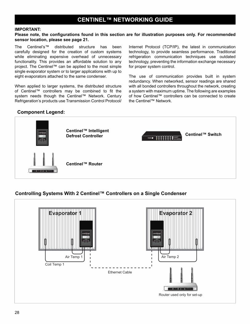
IMPORTANT:Please note, the configurations found in this section are for illustration purposes only. For recommended sensor location, please see page 21.
Component Legend:
Centinel™ IntelligentDefrost Controller22
22
ENTER
BACK
by Century Refrigeration
22
((( (((PWR SYS WLAN 4 3 2 1 WAN USB QSS
Centinel™ Router
1 2 3 654 7
Link/ACT
100/1000MbpsPOWER
Centinel™ Switch
Controlling Systems With 2 Centinel™ Controllers on a Single Condenser
Evaporator 1
Coil Temp 1
Air Temp 1
KE2 EvaporatorEfficiency
TM
thermsolutions
ENTER
BACK
22
TM
Ethernet Cable
Air Temp 2
Evaporator 2
Router used only for set-up
2222
ENTER
BACK
by Century Refrigeration
22 22
22
ENTER
BACK
by Century Refrigeration
22
((( (((PWR SYS WLAN 4 3 2 1 WAN USB QSS
CENTINEL™ NETWORKING GUIDE
The Centinel’s™ distributed structure has been carefully designed for the creation of custom systems while eliminating expensive overhead of unnecessary functionality. This provides an affordable solution to any project. The Centinel™ can be applied to the most simple single evaporator system or to larger applications with up to eight evaporators attached to the same condenser. When applied to larger systems, the distributed structure of Centinel™ controllers may be combined to fit the system needs though the Centinel™ Network. Century Refrigeration’s products use Transmission Control Protocol/
Internet Protocol (TCP/IP), the latest in communication technology, to provide seamless performance. Traditional refrigeration communication techniques use outdated technology, preventing the information exchange necessary for proper system control.
The use of communication provides built in system redundancy. When networked, sensor readings are shared with all bonded controllers throughout the network, creating a system with maximum uptime. The following are examples of how Centinel™ controllers can be connected to create the Centinel™ Network.
29
KE2 EvaporatorEfficiency
TM
thermsolutions
ENTER
BACK
22
KE2 EvaporatorEfficiency
TM
thermsolutions
ENTER
BACK
22
KE2 EvaporatorEfficiency
TM
thermsolutions
ENTER
BACK
22
WAN USB QSS
Router
MODIFY STATUS
KE2 Therm Evaporator Efficiency
IP Address: 10.10.50.51 Location: Walk-in FreezerMac Address: 00.04.A3.12.07.87
ABC Contracting(888)555-3358
All ClearCompressorOn
System ModeCool
Evaporator FanOff
Room Temp-8.5 F
Coil Temp15.4 F
Sat Temp46.0 F
Superheat0.0 F
Valve PositionManual
Suct Pressure96.2 F
Suct Temp87.7 F
Dig Input 3Dis
DefrostOff
Aux TempDis
Dig Input 1Closed
Dig Input 2Dis
Home SetpointsNetworkSettings
TM
thermsolutions
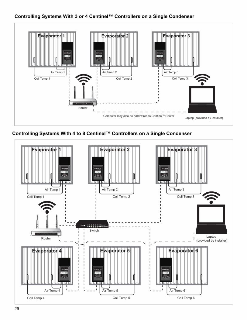
Laptop (provided by installer)Computer may also be hard wired to CentinelTM Router
Evaporator 1 Evaporator 2 Evaporator 3
Coil Temp 1
Air Temp 1 Air Temp 2
Coil Temp 2
Air Temp 3
Coil Temp 3
2222
ENTER
BACK
by Century Refrigeration
22 22
22
ENTER
BACK
by Century Refrigeration
22 22
22
ENTER
BACK
by Century Refrigeration
22
((( (((PWR SYS WLAN 4 3 2 1 WAN USB QSS
Controlling Systems With 4 to 8 Centinel™ Controllers on a Single Condenser
KE2 EvaporatorEfficiency
TM
thermsolutions
ENTER
BACK
22
KE2 EvaporatorEfficiency
TM
thermsolutions
ENTER
BACK
22
MODIFY STATUS
KE2 Therm Evaporator Efficiency
IP Address: 10.10.50.51 Location: Walk-in FreezerMac Address: 00.04.A3.12.07.87
ABC Contracting(888)555-3358
All ClearCompressorOn
System ModeCool
Evaporator FanOff
Room Temp-8.5 F
Coil Temp15.4 F
Sat Temp46.0 F
Superheat0.0 F
Valve PositionManual
Suct Pressure96.2 F
Suct Temp87.7 F
Dig Input 3Dis
DefrostOff
Aux TempDis
Dig Input 1Closed
Dig Input 2Dis
Home SetpointsNetworkSettings
TM
thermsolutions
KE2 EvaporatorEfficiency
TM
thermsolutions
ENTER
BACK
22
KE2 EvaporatorEfficiency
TM
thermsolutions
ENTER
BACK
22
KE2 EvaporatorEfficiency
TM
thermsolutions
ENTER
BACK
22
KE2 EvaporatorEfficiency
TM
thermsolutions
ENTER
BACK
22
1 2 3 654 7
Link/ACT
100/1000MbpsPOWER
Evaporator 1 Evaporator 2 Evaporator 3
Evaporator 4 Evaporator 5 Evaporator 6
Coil Temp 1
Air Temp 1 Air Temp 2
Coil Temp 2
Air Temp 3
Coil Temp 3
Air Temp 4 Air Temp 5 Air Temp 6
Coil Temp 4 Coil Temp 5 Coil Temp 6
Router
Switch
Laptop (provided by installer)
2222
ENTER
BACK
by Century Refrigeration
22 22
22
ENTER
BACK
by Century Refrigeration
22 22
22
ENTER
BACK
by Century Refrigeration
22
2222
ENTER
BACK
by Century Refrigeration
22 22
22
ENTER
BACK
by Century Refrigeration
22 22
22
ENTER
BACK
by Century Refrigeration
22
((( (((PWR SYS WLAN 4 3 2 1 WAN USB QSS
1 2 3 654 7
Link/ACT
100/1000MbpsPOWER
Controlling Systems With 3 or 4 Centinel™ Controllers on a Single Condenser
30
CENTINEL™ NETWORK SET-UP
All Centinel™ controllers are set up by the factory prior to shipment. The following network setup instructions are for the replacement of a Centinel™ controller that requires bonding to existing Centinel™ controllers in the system.
1. Wire NetworkA laptop computer must be connected to the Centinel™ via a CAT5 cable in order to program the controller. If multiple Centinel™ controllers are present, they will be wired to an Ethernet switch. The computer should be connected to the switch using a CAT5 patch cable.
If a Centinel™ router is present in the system, or if a temporary use Centinel™ router is available, it can be connected to the Centinel™ switch or directly to the Centinel™ units. The computer will then be connected to the router.
2. Establish a Connection
For the computer to communicate to the Centinel™ without a router, it must have an IP address in the same range as the Centinel™ it is being connected to. For example, if the Centinel™ IP address is 10.10.70.29, the computer IP address should be set to 10.10.70.1. The Centinel™ address can be found on the sticker on the back of the controller. If your computer does not automatically bring up the set-up page, please see step 9.
Once the router is connected or the IP address of the computer has been changed, open an internet browser window and enter the IP address of the Centinel™ in the address bar.
3. Login
Once connected, the controller set-up screen will appear in the browser window behind a loading image. After approximately 30 seconds, the loading image will disappear. Click the red “Login” button at the bottom of the screen and enter your factory password, see page 29.
4. Enter Setpoints
Click the “Setpoints” icon to begin entering the controller setpoints. The information packet included with each Centinel™ controller contains a printout of each setpoint page and shows what each parameter should be set to. Once all the setpoints on a page have been set, click the “Save” button at the bottom of the page. Navigate away from the page you just updated and return to it to ensure set points were saved. If you leave the page before clicking save, the changes will be lost. After a time delay, the controller
will automatically log out so this process should be performed quickly. If the controller logs out, the user must log back in, and any setpoints entered after the last click of the “Save” button will not be saved.
5. Enter Settings
Enter job site information specific to each controller (phone number, location, company, etc.) If this information is not available, the serial number of the Centinel™ controller will suffice.
6. Network
On the Network page, click “Discover” to import the IP information from each Centinel™ controller on the network. Once the controllers are brought up, click “Bond” and then “Save.” Now, all connected Centinel™ controllers will communicate with each other for cooling and defrost timing as well as sensor readings. Only bond controllers that are intended to coordinate their cooling and defrost operations together. Once the new controllers are bonded via the first controller, you do not need to visit the Network page for any additional controllers.
7. Add Additional Centinel™ Controllers
Once the first controller is set up, all additional controllers must have the same data entered on the Setpoints page. Repeat steps 1 through 6 for each of the remaining Centinel™ controllers.
8. Save Screen Shots
After all setpoints and settings have been entered and saved, close the internet browser. Reopen the browser and navigate to the IP address of the previously configured Centinel™. Ensure all settings and setpoints are correct and take a screen shot using “Alt + PrintScreen” on your keyboard. This will take a screen shot of the active window only. Save a screen shot of the Setpoints pages and the Settings page for future use.
9. Change IP Address
The Centinel™ requires setup via HTTP interface which is accessed by entering the IP address of the device into your computer’s internet browser address bar. In some cases, the IP address for the device will not be in the same range as the IP address of your computer. They must be in the same range in order to communicate.
31
The process to set your computer IP address to allow this communication will vary based on your operating system. The following instructions are for Windows XP:
• Open the Control Panel.
• Open Network Connections.
• Open Local Area Connection.
• Click Properties in the lower left corner.
• In the box that appears, there will be a window labeled “This connection uses the following items.” Inside this window, click “Internet Protocol (TCP/IP)” and the click Properties.
• Click the radio button for “Use the following IP address.”
• In the IP address field, enter an address within the same range of the device you are trying to connect to. For example, if the device address
is 10.10.70.29, set the computer IP address to 10.10.70.1. The Subnet mask should be 255.255.255.0 and the Default Gateway can be left blank.
• Click OK, OK, Close, and “X” to close all windows.
10. Connect
Open Internet Explorer. A message will display that reads something similar to “Internet Explorer cannot connect to this page.”
Enter the IP address for the controller to which you are connecting in the address bar. It will take a few minutes for the connection to be made.
After completing work on your device you will need to go back to your computer’s TCP/IP settings (as outlined in step 9) and change them back to “Obtain an IP Address Automatically.”
CENTINEL™ EMAIL ALERT SET-UP
The steps below will detail the process for setting up the Centinel controller to send email alarm alerts. This setup uses the default host of [email protected] for the email service. Advanced setups including alternative email hosting should be executed by the IT staff overseeing the specific installation. This setup procedure assumes the use of a Centinel™ Router and that a wired Internet connection is available and connected.
1. Navigate to the “Settings” tab.
2. Log in using password “2222.”
3. In the bottom-most drop down menu, select the port “Port 465.”
4. Click “Save.”
5. In the “Email Address” field on the far left, type the desired notification email address.
6. Update the “Location,” “Company,” and “Phone Number” with the proper contact information.
7. Click “Save.”
Note: Mobile phones can have emails sent to them using the carrier’s email to text format. AT&T uses the format [email protected], while Verizon uses the format [email protected]. Contact your mobile phone service provider for more information.
Network set-up beyond the confines of this IOM is not fully supported by the Century Refrigeration Service Department. Higher levels of networking may require third party personnel that are specialized in networking. The Century Refrigeration Service Department may be contacted for questioning; however, the end user may be directed to consult a specialist for set-up assistance and will incur the costs for those services.
32
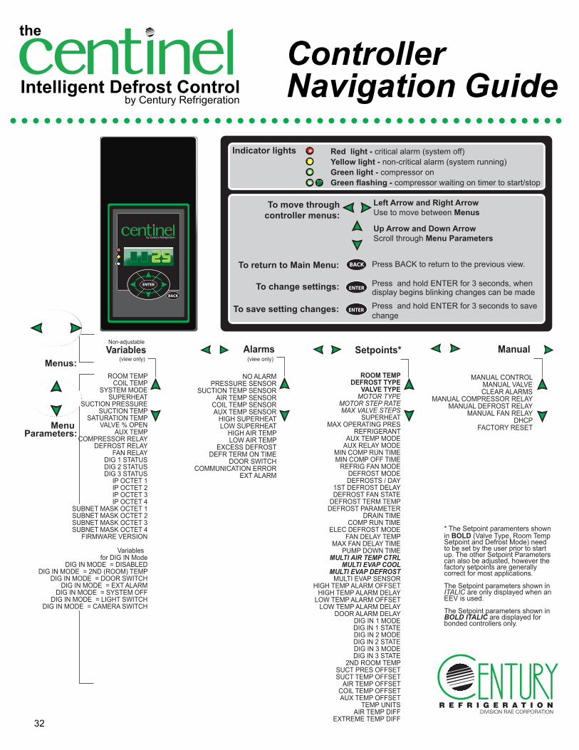
Left Arrow and Right ArrowUse to move between Menus
Up Arrow and Down ArrowScroll through Menu Parameters
ENTERPress and hold ENTER for 3 seconds, when display begins blinking changes can be made
BACK Press BACK to return to the previous view.
ENTER Press and hold ENTER for 3 seconds to save change
To change settings:
To save setting changes:
To move throughcontroller menus:
To return to Main Menu:
Indicator lights Red light - critical alarm (system off)Yellow light - non-critical alarm (system running)Green light - compressor onGreen flashing - compressor waiting on timer to start/stop
Menu Parameters:
Menus:Variables
(view only)
Non-adjustable
ENTER
ENTER
ROOM TEMPCOIL TEMP
SYSTEM MODESUPERHEAT
SUCTION PRESSURESUCTION TEMP
SATURATION TEMPVALVE % OPEN
AUX TEMPCOMPRESSOR RELAY
DEFROST RELAYFAN RELAY
DIG 1 STATUSDIG 2 STATUSDIG 3 STATUS
IP OCTET 1IP OCTET 2IP OCTET 3IP OCTET 4
SUBNET MASK OCTET 1SUBNET MASK OCTET 2SUBNET MASK OCTET 3SUBNET MASK OCTET 4
FIRMWARE VERSION
Variables for DIG IN Mode
DIG IN MODE = DISABLEDDIG IN MODE = 2ND (ROOM) TEMP
DIG IN MODE = DOOR SWITCHDIG IN MODE = EXT ALARM
DIG IN MODE = SYSTEM OFFDIG IN MODE = LIGHT SWITCH
DIG IN MODE = CAMERA SWITCH
NO ALARMPRESSURE SENSOR
SUCTION TEMP SENSORAIR TEMP SENSOR
COIL TEMP SENSORAUX TEMP SENSOR
HIGH SUPERHEATLOW SUPERHEAT
HIGH AIR TEMPLOW AIR TEMP
EXCESS DEFROSTDEFR TERM ON TIME
DOOR SWITCHCOMMUNICATION ERROR
EXT ALARM
Alarms (view only)
ROOM TEMP
DEFROST TYPEVALVE TYPE
MOTOR TYPEMOTOR STEP RATEMAX VALVE STEPS
SUPERHEATMAX OPERATING PRES
REFRIGERANTAUX TEMP MODE
AUX RELAY MODEMIN COMP RUN TIMEMIN COMP OFF TIME
REFRIG FAN MODEDEFROST MODEDEFROSTS / DAY
1ST DEFROST DELAYDEFROST FAN STATE
DEFROST TERM TEMPDEFROST PARAMETER
DRAIN TIMECOMP RUN TIME
ELEC DEFROST MODEFAN DELAY TEMP
MAX FAN DELAY TIMEPUMP DOWN TIME
MULTI AIR TEMP CTRLMULTI EVAP COOL
MULTI EVAP DEFROSTMULTI EVAP SENSOR
HIGH TEMP ALARM OFFSETHIGH TEMP ALARM DELAY
LOW TEMP ALARM OFFSETLOW TEMP ALARM DELAY
DOOR ALARM DELAYDIG IN 1 MODEDIG IN 1 STATEDIG IN 2 MODEDIG IN 2 STATEDIG IN 3 MODEDIG IN 3 STATE
2ND ROOM TEMPSUCT PRES OFFSETSUCT TEMP OFFSET
AIR TEMP OFFSETCOIL TEMP OFFSETAUX TEMP OFFSET
TEMP UNITSAIR TEMP DIFF
EXTREME TEMP DIFF
Setpoints*
MANUAL CONTROLMANUAL VALVECLEAR ALARMS
MANUAL COMPRESSOR RELAYMANUAL DEFROST RELAY
MANUAL FAN RELAYDHCP
FACTORY RESET
Manual
* The Setpoint paramenters shown in BOLD (Valve Type, Room Temp Setpoint and Defrost Mode) need to be set by the user prior to start up. The other Setpoint Parameters can also be adjusted, however the factory setpoints are generally correct for most applications.
The Setpoint parameters shown in ITALIC are only displayed when an EEV is used.
The Setpoint parameters shown in BOLD ITALIC are displayed for bonded controllers only.
ENTER
BACK
22
by Century Refrigeration
by Century Refrigeration
the
Intelligent Defrost Controlby Century Refrigeration
ControllerNavigation Guide

P.O. Box 1206 • Pryor, OK 74362 • (918) 825-7222 • FAX (800) 264-5329
www.Century-Refrigeration.comBulletin# C-CENT-IOM-0113