Embed Size (px)
Citation preview

BV THERMAL SYSTEMS, LLC.
Mercury Series Fluid Chillers
Operation Manual
1/4 through 10 Horsepower thermal systems Both Air & Water Cooled
Quality is the Difference 1064 Woodland Ave. Ste. K
Modesto, CA 95351 Tel: 209-522-3701 Fax: 209-522-3733
www.bayvoltex.com

Notice
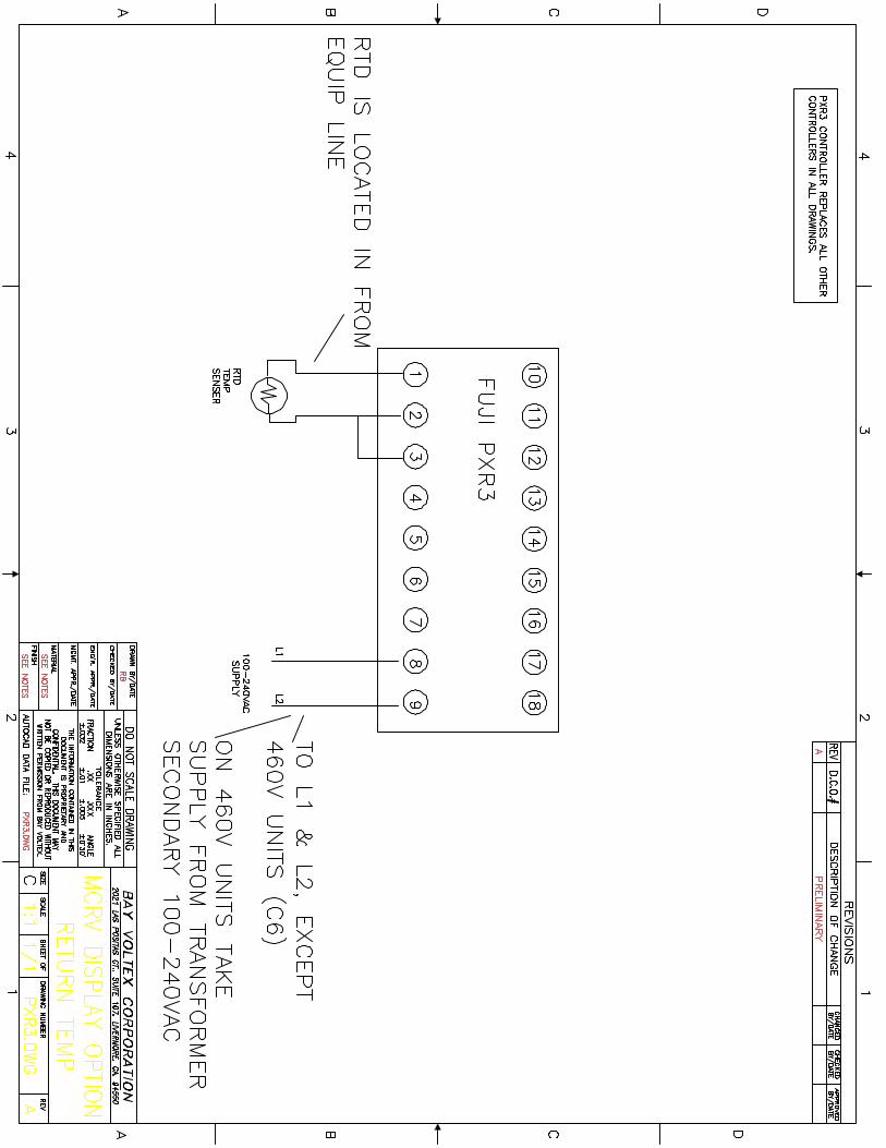
This manual is preliminary. Packaging on some models may differ as we are continually making improvements to our product to serve you better. Regarding electrical schematics; breaker amperages may change due to unit configuration. Actual wiring will still adhere to depicted layout. ELECTRICAL SCHEMATICS: To find the schematic for your chiller, look in the lower left corner of the schematics where you will find the schematic legend. For example if you have an MCLT050-E1, you will use schematics MCE1, MCLT & MCE1C1. MCE1 shows the control scheme, MCLT shows the additions to that for an LT unit and MCE1C1 shows the high voltage portion of your system.

Table of Contents
Safety Precautions 5 Theory of Operation 7 Installation Procedure 9 Rack-Mount Chillers 11 Low Temp Chillers 12 Outdoor Chillers 13 High Temp (HT) & Extended Temp (ET) Chillers 14 Startup Procedure 15 Pressure Regulation/Fluid Bypass Safety 15 Chiller Maintenance 16 Standard Temperature Controller 17 Safeties Package (E1 option) 20 Remote Control RS-232/485 (E2 & E3 option) 23 Watlow Temperature Controller (E4 option) 25 Fault Diagnostics Guide 26 Spare Parts 28 Service Procedure 29 Warranty 30 Pump Troubleshooting 31 Pump Curve 4.2GPM (standard pump) 35 Pump Curve 2.2 GPM (standard pump) 36

Facility drawings, plumbing, refrigeration & electrical schematics 37-on Fuji Controller PXR3 Manual (Standard & E1, E2 & E3 controller) On Disk Fuji Modbus RTU Protocol (For making your remote software) On Disk PXR-LITE Manual (Complimentary Windows based remote software) On Disk MTH C series centrifugal pump manual On Disk MTH C series centrifugal Single Phase Curves On Disk MTH C series centrifugal Three Phase Curves On Disk MTH T31-41 series turbine pump manual On Disk MTH T series pump curves On Disk Watlow Controller Manual (For analog remote customers) On Disk

Safety Precautions Read this for safe use.
The Mercury Series chillers are designed to be used per the instructions in this manual. Used in any other fashion it may not perform to specification and may be less safe to operate in general. Failure to heed warnings and instructions listed in this manual may void the warranty, damage the unit, damage other equipment and possibly cause serious personal injury. If you have any questions concerning anything in this manual consult our factory service representatives at 877-275-1682 toll free.
1. Do not use automotive anti-freeze in the chiller. It will destroy various components in the plumbing circuit as well as void the warranty. If you must please call our engineering dept. first.
2. If the set point is 10 degrees Celsius or below use an additive to
prevent freezing. Bay Voltex recommends industrial grade ethylene glycol. For very low temperature applications -30 to -40C other fluid types may be more suited to your specific application, please call us at 209-522-3701.
3. Always ensure that the chiller is connected to a grounded power
source. Failure to comply can result in serious injury or death. 4. Do not place the chiller where excessive heat, moisture or corrosive
materials are present. 5. Never connect the plumbing TO EQUIPMENT and FROM EQUIPMENT
bulkheads of the chiller to a pressurized source or in a manner other than that described in the installation section of this manual.
6. Any service to the chiller should be performed by qualified
technicians only. Failure to comply could void the warranty. 7. Do not operate the chiller without fluid in the reservoir. 8. Do not operate the chiller without the outer panels. Failure to
comply could result in personal injury. 9. Do not operate a damaged unit. I.E. leaking, excessively noisy,
frayed power cord, etc. Contact Bay Voltex service personnel for instructions.
10. Do not operate the unit without the reservoir fill cap installed. It can result in damage to the unit.

Safety Precautions
Read this for safe use. 11. Transport the unit with care. Sudden jolts or drops can damage the
unit. 12. Always disconnect power before performing any service on the
chiller. 13. Completely drain the unit before storage or shipment. Failure to
comply can result in serious damage to the unit and void the warranty.
Theory of Operation
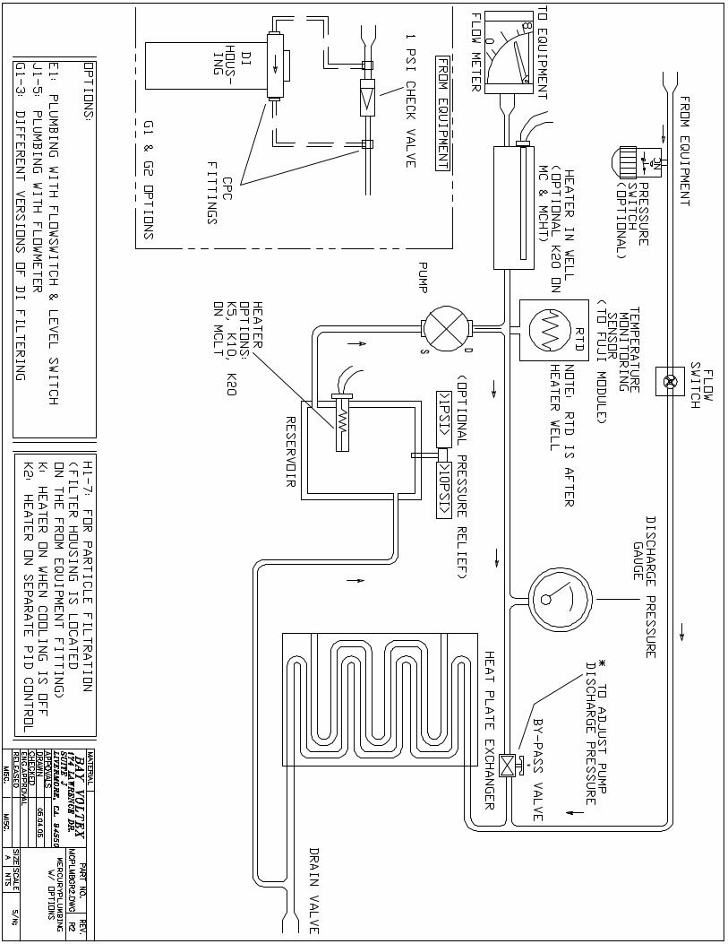
Chiller Complete System The Mercury chiller incorporates a refrigeration circuit, an internal plumbing circuit with a reservoir and an electronic control circuit. The pump will draw the fluid medium to be cooled from the reservoir and discharge it to the TO EQUIPMENT bulkhead on the rear of the unit. This fluid will flow through a closed loop to remove heat from the end user's equipment. The fluid will return through the FROM EQUIPMENT bulkhead and pass through a refrigerated plate heat exchanger. Here heat is removed before re-entering the reservoir.
Bypass Loop The chiller should not be operated with either the TO EQUIPMENT or FROM EQUIPMENT lines shut or otherwise blocked off. In the event this should occur protection is provided via an externally adjustable pressure bypass valve located on the front control panel. When actuated partial or full pump flow will be re-directed through the refrigerated plate heat exchanger back to the reservoir. This will protect the fluid pump and motor from a "dead-head" situation. As well it protects the plate heat exchanger from freezing and rupturing.
Refrigeration Circuit The refrigeration circuit in the Bay Voltex Mercury Series chillers combines twenty years of the ultimate in reliability with the latest refrigeration concepts and components. Bay Voltex has used the hot-gas bypass method of operation from its first day of business. The advantage of this method is prolonged compressor life, tighter temperature stabilities and energy efficiency. Our cooling circuit control is achieved with a break-through design solenoid valve that extends life capacity twenty times that of the previous highest rated design. As well, a thermostatic expansion valve that tracks with your set temperature yields performance and capacity head and shoulders above the other, "cut-every-corner", chillers on the market. This method of refrigerant metering also saves energy by yielding faster and more efficient results allowing the compressor to work less. The circuit functions as follows. The compressor takes in refrigerant vapor, compresses it in to a high temperature gas and discharges it into the condenser. The condenser via air-over heat removal condenses the gas into a high-pressure liquid which circulates into a receiver. The receiver stores the liquid refrigerant until called for by the cooling solenoid. The microprocessor controller will anticipate the need for cooling and open the solenoid valve. The liquid refrigerant passes through the solenoid to the thermostatic expansion valve, (TEV). The TEV will meter the proper amount of refrigerant into the plate heat exchanger. The plate heat exchanger has two separate circuits separated by thin metal plates with high conductivity properties. One side is for

Theory of Operation
Refrigeration Circuit continued refrigerant flow the other for the fluid to be cooled. As the fluid and refrigerant pass through the plate heat exchanger the refrigerant evaporates pulling heat out of the fluid. The cycle is completed by the refrigerant exiting the plate heat exchanger back into the suction side of the compressor. Finally, when cooling is not called for a hot gas bypass valve senses the low suction pressure and opens the discharge side of the circuit to the plate heat exchanger and back to the compressor.

Installation Procedure
Electrical Requirements Ensure the voltage of the power source meets the specified unit voltage, +/- 10%. The correct voltage will be specified on the serial number tag under the power cord. Make sure the voltage source is properly grounded.
Air Cooled Unit Location Mercury chillers with air-cooled condensers require proper ambient airflow around the unit. Air is drawn in the front of the unit and discharged out the rear and sides. A minimum side and rear clearance of 18" should be maintained. As well, ensure the location selected doesn't allow discharged air to re-circulate into the front intake. Once a suitable location is confirmed lock the four locking casters.
Plumbing Connections Most chillers all have 1/2" FPT connections on the rear of the unit. See your quote for exact size. The bulkhead labeled TO EQUIPMENT is connected to the inlet of your application. The bulkhead labeled FROM EQUIPMENT is connected to the outlet of your application. When possible use opaque plumbing lines between the chiller and your application. This will prevent algae growth in the fluid due to light exposure. Keep the lines between the chiller and your application as short as possible to minimize heat gain and pressure drop. Do not use fittings of a material susceptible to corrosion as this may contaminate the chiller and your application. On units with the ultra pure plumbing or D.I. options fittings used should be stainless steel or nylon. Use lines that are compatible with the operating parameters of the system. Maximum pressure is 125 PSI; maximum operating temperature is listed in your quote. A thread sealing applicant such as Teflon tape should be used on plumbing connection to prevent leaks.
Filling The Reservoir Remove the RESERVOIR ACCESS COVER from the top of the unit. Remove the RESERVOIR FILL CAP from the reservoir by unscrewing it counter clockwise. Fill the reservoir with clean filtered water, or when running below 10 degrees Celsius add a freezing point depressant such as ethylene glycol in a 50/50 mixture with clean filtered water. If set-point is -10 C or below use a 50/50% glycol/water mixture.

Installation Procedure
Filling The Reservoir Continued Start the unit by switching the unit breaker located on the front panel. Fill the reservoir to a ½" below the fill port. The reservoir level should drop as the lines to your application fill with fluid. Before the reservoir drains stop the chiller by switching the breaker off and refill the reservoir. Repeat this process until the complete circuit is filled with fluid. If you have the optional safety package, which includes a reservoir level sensor, the chiller will automatically stop running when the reservoir level drops to a predetermined point. Again refill the reservoir, press the RESET button on the front control panel and chiller will operate. Repeat this process until the complete circuit is filled with fluid. The correct level is approx. 1" below the fill port. Cap the reservoir and replace the RESERVOIR ACCESS COVER.
Starting The Unit The unit can again be started and left running. Inspect all plumbing connections for signs of leakage. Repair connections if necessary, top up the fluid in the reservoir and restart the unit. For units with E1 option press Reset on front panel if the unit is not starting, then press ON/OFF. Otherwise the main breaker is your On/Off switch.
Changing The Set-point and Alarms See the section of this manual titled Mercury Standard Package Controller or Mercury Optional Controller.
Control Package E1 (Safety Interlocks) &RS-232/485 Options For E1 a standard DB-9 cable is used, on RS232/485 a Null Modem cable is required. These can be purchased from Bay Voltex as accessories. See sections in this manual regarding these specific options for further information.
Water-Cooled Units Connect bulkhead on rear of unit labeled Facilities Water In to your supply line. Connect bulkhead on rear of unit labeled Facilities Water Out to your drain. Supply water to the unit should not exceed 85 F. Supply water pressure should be between 40 to 80 PSI maximum.

Mercury Rack-Mount Installation Controls and User Interface
All front panel controls and or user interfaces are the same as the standard Mercury chillers. The only exception is the fluid bypass. The fluid bypass controls the pressure of the chiller pump and therefore the flow of the chiller to the tool being cooled. On the Mercury rack-mount units with a positive displacement pump, (options P1-P4), the bypass or pressure/flow adjustment is inside the unit on top of the pump off the plumbing assembly attached to the discharge port of the pump. The adjustment is a brass T-handle arrangement. On centrifugal pump units, there is no pressure/flow adjustment as it is not necessary.
Plumbing Connections The TO and FROM EQUIPMENT connections are both on the rear of the rack-mount unit. The FROM equipment is located directly above the TO equipment. Both connections are labeled for your convenience. Filter Options The rack-mount units are available with the same filter options as the standard units. However due to the compactness of the rack-mount style unit there is not space for attaching the filter housings to the unit. Our solution is to include a filter kit. For example on the H, 2, 6 & 7 particle filter options the unit is shipped with the appropriate barb fitting attached to the FROM equipment bulkhead. The rest of the filter kit components are in a package labeled FILTER KIT. Simply cut the included push-lok hose to the desired length attach it to the FROM equipment barb fitting, and attach the other end to the filter housing outlet. Next attach the remaining hose to the filter housing inlet and the filter kit is installed. The filter housing can be allowed to rest on the floor, or be mounted on the wall near the chiller. Fill Port The reservoir fill port is a 2 ½” cap on front of chiller. Remove the cap to fill unit and follow the normal filling procedure after that.
Mercury Low Temp Installation
Mercury low temp units are designed to hold the rated load from 0 to -40C depending upon your requirement. Operation & Maintenance Instructions
1. Aside from the special instructions listed below, the instructions in the rest of the manual are also applicable.
2. The fluid used to fill your Low Temp chiller should suitable for the
application. We recommend a 60/40 ethylene glycol/water mixture. Other fluids are available such as Dynalene, alcohol or methanol mixtures. Whatever fluid you choose ensure that its freezing point is at least 15C or 27F below the fluid temperature you are going to run if possible. Dynalene requires special seals as well.
3. It is very important when topping up the fluid after a maintenance or if there has been fluid loss that the same mixture is added and not straight water. This has led to heat exchanger ruptures for customers in the past.
4. When connecting hose to the TO & FROM EQUIPMENT and to your tool the hoses must be insulated to prevent icing up and losing most of the units heat removal capacity. ¾” wall insulation is recommended.
5. It is recommended that the chiller is allowed to achieve the SET temperature before applying the heat load.
6. The adjustments on the refrigeration valves and components of a Low Temp chiller are very critical, only certified refrigeration technicians should attempt servicing the chiller. We also recommend that that the technician contact Bay Voltex service for assistance 877-275-1682 toll free.
7. Consult either the standard controller or E1, 2, or 3 controller sections
on how to operate the user interface for your system.

Mercury Outdoor Chillers Installation
Mercury outdoor chillers are built to withstand the temperatures and conditions of year round outdoor installation. Operation & Maintenance Instructions
1. Aside from the special instructions listed below, the instructions in the rest of the manual are also applicable.
2. Install the chiller so that any side with air flow vents has 2’ to 3’ of
clearance between the chiller and any obstructive object.
3. When not making temperature adjustments or interfacing with the safety
interlocks make sure that the NEMA 4X enclosure is securely closed.
4. Install the chiller where any LED or LCD displays will be protected from direct sunlight.
5. Regularly inspect and clean the condensing coil of the outdoor chiller. Depending upon your area it may be necessary to clean the coil as often as every three months or as seldom as every few years. Regular inspections over the first year of service will show often cleanings are necessary.
6. It is recommended that a refrigeration industry type aluminum coil cleaning fluid be used every few years. Call Bay Voltex service at 877-275-1682 toll free for the cleaning fluid.

Mercury High Temp (HT) & Extended Temp (ET) Chillers Installation
Important points for chillers running 35C and above.
TOO AVOID INJURY OR CHILER DAMAGE FOLLOW THE INSTRUCTIONS BELOW.
1. On HT or ET temp chillers with the Fuji PXR3 model controller the Temp Alarm
setting is set to 5 degrees above the high limit of the controller; i.e., if your temp range is 5-50C the alarm setting will be 55C, if your temp range is 5-100C the alarm setting is
105C. If you need to adjust this setting it is “AL 1” in the first parameter block of the controller. 2. On units with heaters running at 35C or above a pressure relief assembly has been added for your safety as well as the chillers. The assembly consists of 3 main parts, 1- a relief bulkhead or hose, 2- a 10 PSI positive pressure relief valve, and 3 - a fill cap mounted manual pressure relief valve.
2a. Whether the chiller is at a high temperature or not, before opening the reservoir or working on the chiller, open the manual pressure relief valve mounted on the reservoir fill cap. 2b. If you have the supply pressure switch option, it is necessary to leave the manual pressure relief valve open at all times to avoid violating the high pressure shutdown.
3. If the chiller is operating at 80C or above and your circulating fluid contains glycol of any type, we strongly recommend a ph or acid level test on the fluid on a monthly basis. If the acid level has increased from the original start-up ph level, drain and refill the chiller. Failure to maintain proper ph level may void part of your chiller warranty. 4. HT or ET temp chillers may have exposed hot surfaces outside the cabinet and definitely inside the chiller cabinet. Heed all warning labels to avoid injury. 5. HT or ET temp chillers may have high pressures in the fluid reservoir whether the equipment is running or not. Always open the manual vent valve before opening the reservoir. 6. If you have the supply pressure switch option do not adjust the gate valves on the pump discharge line or the TO EQUIPMENT bulkheads without calling the factory for assistance. They have been adjusted at the factory to meet your specification. 7. On high temp units wide temperature cycling can cause leaks over time. For example if you constantly change the set-point more than 40C up and down check for leaks on a monthly basis to head off more serious failures later on. 8. Do not reprogram the controller to operate above or below the factory range already set for your MCHT or MCET chiller. The materials of our chiller may not be suitable for lower or higher temperatures than were originally specified. As well the refrigeration valves were set to work with the temp ranges that were factory set on the temperature controller.

Startup Procedure
1. Turn on the chiller by switching the ON/OFF, I/O (circuit breaker) switch to the ON/I position. If you have the E1 safeties package press the ON/OFF button on the keypad. Press RESET ALARM, then ON again if it doesn’t start. 2. Set the set-point temperature by using controller on the front panel by
following these steps: • Press the SELECT key once to display the set-point temperature. • Use the UP and DOWN arrows to change the set-point temperature
value. (For Watlow controllers only use the arrow keys to adjust). • Press the SELECT key again to enter the new set-point temperature.
3. Allow the chiller to operate for a few minutes and inspect the plumbing connections for signs of leakage. Repair any leaking connection with the chiller off. Top up the reservoir and restart the unit. Pressure Regulation
Fluid Bypass Safety Note: Some units with centrifugal pumps have no bypass. 1. The Mercury chiller has an externally adjustable safety bypass/pressure regulator on the left side of front control panel. The Primary purpose of this valve is to protect the pump from a "dead head" or no external flow situation. As well, the plate heat exchanger is protected from freezing. The bypass loop passes through the plate heat exchanger before reentering the reservoir. This flow through the plate doesn't allow time for the fluid to freeze and expand, which would rupture the plates. (Some OEM models have internal bypasses). 2. The Secondary purpose of the externally adjustable bypass valve is to regulate pressure in the closed loop circuit between the chiller and your application.

Chiller Maintenance
Warning A qualified technician should carry out all necessary maintenance internal to the chiller. Like any other machine a chiller requires periodic maintenance to obtain maximum efficiency and performance. Standard Maintenance Air-Cooled 1. Ensure fluid level is adequate. 2. Inspect To & From Equipment lines and chiller for signs of leakage. 3. Clean air-cooled condenser with compressed air or a brush to remove dust. 4. Ensure that chiller is maintaining set temperature. 5. If non-opaque fluid lines are used to connect chiller inspect for signs of organic growth. 6. If dirt, oil, etc. does not appear to come off condenser coil or heat removal seems dissipated, we can provide a coil cleaning liquid that will restore the coil surface to like new condition. Call Bay Voltex service 877-275-1682. 7. For low-temp chillers, regularly check the freezing point of your fluid. Standard Maintenance Water-Cooled 1. Ensure fluid level is adequate. 2. Inspect To & From Equipment lines and chiller for signs of leakage. 3. Ensure that chiller is maintaining set temperature. 4. If non-opaque fluid lines are used to connect chiller inspect for signs of organic growth. 5. Inspect Facilities Water In & Out hoses for signs of leakage. 6. Ensure that Facilities Water supply is between 40 to 80 PSI and no more than 85F. 7. For low-temp chillers, regularly check the freezing point of your fluid.

Mercury Series Standard Package Temperature Controller
Front Panel Description 1. Set value indication lamp SV 1 2. Control output or cooling on lamp C1 3. Alarm indication lamp AL1 2 4. SELECT key 5. UP key 6. DOWN key 3 7. MAIN display 4 5 6 7 Front Panel Description 1. The "set value" indicator comes on when a set value or temperature set point is displayed. 2. The control output or cooling on lamp comes on when the cooling solenoid is being engaged. 3. The alarm indication lamp comes on when the alarm is activated and blinks while the alarm value is being set. 4. The select key is used to choose menu options between three different parameter blocks in the controllers program. 5. The up key is used to change set point and parameter values. 6. The down key is used to change set point and parameter values. 7. The MAIN display will show set point and actual temperatures as well as parameter symbols and codes. (For a complete list of parameters see Fuji Electric manual included with your Mercury chiller). Standard operation can be accomplished with this manual. Temperature Control Operational Description Your Mercury chiller uses a microprocessor to achieve +/- 0.1 Celsius temperature stability . To do this the temperature controller measures cooling rate based on your heat load as well as the overall time it takes to complete the temperature swing above and below set point. These can be affected by individual circumstances at different installation sites, i.e. ambient conditions, flow reductions, heat load variances, etc.
Some Mercury configurations will not achieve 0.1C stability; consult your quote for expected temperature stability.

Mercury Series Standard Package Temperature Controller If used according to the manual and on steady state heat load the Mercury chiller will perform reliably to its +/-0.1 Celsius specification.
Temperature Control Easy Operation 1. After unpacking and installing the chiller with the guidelines in the installation section of this manual turn on the chiller. 2. The temperature controller's Main display will initially show four green dots, then display the actual temperature of the fluid in the cooling loop. 3. Press SELECT once and the SV or set value indication lamp will light. Use the UP and DOWN arrows to adjust the set value. Press SELECT again to enter the value. 4. Allow the chiller to bring the fluid near the process value. Press and hold SELECT for three seconds. The alarm light will start blinking and the main display will show the alarm set value. Press SELECT again and the Autotune parameter symbol will be displayed, "AT 0". Press UP once and "AT 1" will be displayed. Press and hold SELECT for three seconds to enter the selection and return to temperature monitoring display. Press SELECT once more to switch from set to actual temperature. During the Autotune process a blinking light will display in the lower right hand corner of the MAIN display. The Autotune process will take between 1 and 30 minutes depending on your process. Our testing has determined that the average test is less than five minutes. Once the light stops blinking your process will hold 0.1 Celsius temperature stability. Note: If the heat load is changed by more than 33%, it may be necessary to run the Autotune process again in order to maintain 0.1 Celsius stability. 5. From the factory, the alarm value is set to 5 degrees C above the upper range of the chiller. This means if the actual temperature rises to the AL 1 setting the unit will shut down if you have the E1 safety package option. For both E1 and non E1 units the remote contact closure will open indicating an alarm condition. 6. To change the MAIN display from Celsius to Fahrenheit, (from the factory it is set to Celsius), press and hold SELECT for six seconds. The main display will show the letter P, use the DOWN arrow to scroll down to the "P-F" parameter. Press select once and the current choice either C or F will be displayed. Use the UP or DOWN keys to make your selection. Press and hold SELECT for three seconds to enter your choice. Note: When changing between C or F, temp ranges, alarms & set-point will need to be readjusted.

Mercury Series Standard Package Temperature Controller 7. Another convenient feature of this temperature controller is the ability to lock out the controller. There are two settings one will prohibit all parameters or settings from being changed. The second setting will allow only the set point or SV to be changed. Press and hold SELECT for three seconds, the alarm set value will be displayed and the alarm light will be blinking. Press select again twice to scroll to the, “LOC", lockout function. Use the UP and DOWN arrows to choose either 1, 2 or 0. Option 0 will allow all parameters to be changed. Option 1 will lock all parameter settings. Option 2 will allow only the main set-point to be changed. 8. The steps above will allow you to operate the controller as intended per use in the Mercury chiller. If you want to know more about the controller or get an error code, consult the Fuji Controller Manual at the back of this manual.
Remote Status Alarm On the rear of the system is a 9 Pin D type connector labeled Alarm. This is for the temperature alarm status. Pins 1 and 9 can be monitored for a temperature deviation alarm, temperature controller, or temperature sensor fault condition. Pins 1 and 9 are configured to be NORMALLY CLOSED when correct.

Mercury Series Control Package 1 Option Code E1
Safeties Package
The E1 package includes a level low sensor for the fluid level in the reservoir, a flow switch and a high-low temperature indicator. The Level Low, Low Flow and Temp High functions have indicator lights on the touch screen as well as audible alarm indication. The temperature alarm light is also located on the temperature controller on the front panel; it will also trigger the audible alarm. All three functions will open the Dry Contact Loop on the 9 Pin D connector located on the rear of the unit when in fault condition, (closed when correct. CONTROLS: ON/OFF - starts and stops the unit RESET - resets a triggered alarm MUTE – mutes or silences the audible alarm REMOTE – changes the unit to remote start mode, note remote status pins 1 & 9 are always active to monitor fault status of chiller SCREEN COLOR – in normal operation the screen is green a visual indication that all is well, when an alarm occurs the screen will turn red to let the user know a fault has occurred. As well the individual interlocks indicator will change to let you know what has happened
RESET ALARM, MUTE & REMOTE ON SWITCHES
LEVEL, FLOW & TEMP LED’S
ON/OF

Mercury Series Control Package 1 / Option Code E1 Safeties Package
Level Low & Low Flow Fill reservoir to ½” below fill port and press RESET ALARM, the level low led will go out. When ON/OFF is pressed, the Low Flow interlock is bypassed for 10 seconds, if after 10 seconds the flow requirements are not met the appropriate alarm will indicate. The unit will shut down. Also if nuisance tripping of the level switch occurs, the indicator will stay violated but the chiller will resart protecting your process but letting you know what has occurred
High-Low Temperature Alarm If your unit doesn't start when powered on, press reset as the temp alarm may be tripped. The alarm from the factory is set to high alarm only. This setting will be 5 degrees C above the range of your chiller. To set the alarm to a high/low or deviation type consult the Fuji PXR3 manual on this disk or call the factory. I/O On/Off The chiller on/off control is on the screen and is designated by ON or OFF. Audible Alarm
The audible alarm will sound when any of the safety interlocks are violated. To Mute the alarm press the MUTE button on the front panel once. Press the MUTE button once more to reactivate the audible alarm. Reset Alarm There is a button on the scren labeled Reset. If a Level, flow or temperature alarm is tripped the unit will shut down. And a LED and audible alarm will sound. As well pins 1 & 9 on the remote connector will open. After correcting the problem press reset alarm to clear the alarm and the PLC. Press ON/OFF to restart the unit. Note: In the ON state if an alarm trips and then corrects itself the unit will auto restart. The LEVEL LOW LED will remain lit though as nuisance tripping with this function can occur. This way you will know what the problem was.

Mercury Series Control Package 1 / Option Code E1
Safeties Package Remote Mode
To operate the Remote functions a female DB9 cable is necessary. On pins 3 & 7 connect two wires and a SPST switch to start and stop the unit. To run in remote mode pins 3 & 7 must be closed. As well you must press the REMOTE button on the control screen once. The Remote button will change to RMT ON to indicate remote mode is engaged. The Dry Contact Fault Status Loop, (pins 1 &9), are always active, they are closed when correct or there are no faults. Connect two wires to pins 1 & 9 to monitor the Dry Contact Fault Status loop. Note: For Low Flow to open fault status loop pins 1&9, the unit must be running in either local or remote modes. When the unit is not running only Low Level and High Temperature alarm will open the status loop. This is to prevent a “false alarm” on your monitoring equipment as Low Flow should only indicate when the unit is supposed to be running. However the low flow LED will come on anytime flow stops.

MERCURY SERIES RS-232/485 Remote Control
Option Codes E2 & E3 Description
Option E2 for RS-232 or E3 for RS-485 remote control is a powerful tool for utilizing the capabilities of the chiller and the Fuji temperature controller. The remote communications only allow communication with the temperature controller, for Remote On/Off and the Fault Monitoring Loop see the Control Package 1 Option E1 portion of this manual. The unit comes with PC compatible software, PXR-Lite. This software allows you to control up to 31 chillers per PC. As well all standard and custom features of the Fuji controller are available at the click of a mouse. If other means of communication are desired the Fuji controller will accept RS-232/485 Modbus RTU. On this disk the Fuji RS-485 Modbus manual is included. This will provide you with the necessary codes and addresses. NOTE: Null Modem cable required for RS-232.
Connections 232/485 On the rear of the unit is a 9 Pin D connector labeled RS-232 or 485. The RS-232 pin out is as follows: pin 2 is RD or receive data, pin 3 is TD or transmit data, pins 4 & 5 are signal ground. A Null modem cable, where pins 2 & 3 are crossed is required. For RS-485 pin-out; pins 1 & 3 are data -, pins 2 & 9 are data +, with pin 5 as ground/signal ground. Or see schematics E2 or E3.
Operation VIA Remote It is recommended that you install and run the unit locally before operating in Remote mode to ensure that the unit is properly installed. Once you are confident that the unit is installed correctly, turnoff the power to the chiller and connect it to a PC running Windows 95 or higher via the appropriate RS-232 cable. Turn on your PC and insert the PXR-Lite CD-Rom. 1. To install the software simply click on the file and it will install itself in a matter of seconds. 2. Turn on the power to your chiller. Go to your Windows Start tab and choose Program Files > PXR-Lite. 3. To initiate remote communications choose the Com Port Setup tab in PXR-Lite. Verify or enter the following choices; PORT = Com1, (or the Com port you are connected to), PARITY = even, and then click OK. The PC display will show a representation of the temperature controller and the current actual and set temperatures. This indicates proper communication. If connection is unsuccessful, restart PXR-Lite before reconnection.

MERCURY SERIES RS-232/485 Remote Control
Option Codes E2 & E3
OPERATION continued The settings for remote control are in the 3rd parameter block of the Fuji controller. The two settings STno and CoM are already set. You only have to connect your cable to your PC and install the PXR-Lite software. If you have RS-485 depending on your equipment, you may need a signal converter. Also if you wish to use your own software the Modbus RTU manual is included on this CD. Or for further information on the PXR-Lite software see the PXR-Lite manual on this disk. Note: If you need to change the parity setting, it must be changed on the controller as well as the PXR-Lite software. CoM parameter, in the 3rd programming block of the Fuji controller changes the parity on the controller 0 = odd, 1 = even, and 2 =No parity. After changing the parity setting on the controller you must cycle the unit power off. The new parity setting will take on power up.

Mercury Series Watlow Controller E4 OPTION
*Notice: The Watlow controller approaches set-point more cautiously than our standard controllers. If you need to get to set-point faster set a lower Temp than you need if cooling down.
CHANGING SET-POINT 1- Use up & down arrows to enter a new set-point. It takes the controller approx. 15 seconds to register a new set-point. 2- To run the AUTOTUNE function, (provides better temperature stability at new set-points or heat loads), follow these steps: A. Press the GREEN button until you see AUT on the bottom red display. B. Press the up arrow key once so the top RED display reads TUNE. C. Press the INFINITY key once to return to temp display mode. D. The controller will go through a measuring process to control the new load/set-point condition to the tightest possible temperature stability. 3- Allow the controller several minutes after the tune process completes, (you will know it’s over because the screen will stop flashing TUNE at you), to achieve set-point. For low-temp units 0c or less it is best to let the unit reach set-point then turn on your load. 4- If you are unsatisfied with the temperature stability, call me at 209-522-3701 x.203. I usually see +/-0.2 – 0.5 with the Watlow controller. I will be glad to help.

Mercury Series Fault Diagnosis Guide
FAULT POSSIBLE DIAGNOSIS PROBABLE CAUSE Unit cools but does not hold temperature under load
Low refrigerant charge
Leak in system piping or component
Unit heats up but will not cool
No refrigerant charge, Hi/Lo pressure switch Tripped for refrigerant
Leak in system piping, bad solenoid or cooling valve Blocked condenser or Not enough facility water
Unit does not control to set point within reason
Excessive heat load or faulty RTD or Controller
Improper measurement of heat load, faulty component
Unit circuit breaker does not hold in
Pump or compressor pulls excessive amperage, faulty circuit breaker
Pump is seized, dirty condenser, bad component
Unit won’t start*
Check power supply
Faulty circuit breaker
Reset Alarm not Pressed after fault Condition is cleared
Fault indication light on, level low, temperature deviation, low flow,(system fail for water cooled units, no facilities water supply)
Unit set to run in remote mode.
No remote cable connected.
Level low, Low Flow or Temperature High light remains illuminated when signal should be correct
Level Switch is stuck Dirty process fluid
Incorrect alarm setting or value for Fuji controller
factory settings changed
Loss of facilities water supply or refrigerant
Refrigerant leak in system piping, facilities water shut off or clogged

Mercury Series
Fault Diagnosis Guide FAULT
POSSIBLE DIAGNOSIS PROBABLE CAUSE
Temperature control is intermittent
Faulty RTD Compressor cycles on Thermal overload No power to solenoid
Loose wire connection, bad component Bad compressor Loose wire connection.
Unit heats only; won’t cool
Open circuit RTD
Loose wire connection, bad component
No flow or pressure in fluid Pump not running Magnet decoupled, circuit broken pump shaft key, clogged suction line, pump motor windings open Excessively low pressure Mis-adjusted or bad Wrong adjustment or bad and flow bypass valve component Temp controller displays RTD is bad or open, bad UUUU connection to controller, actual temp PV exceeds P-SU upper limit by 5% of full scale Temp controller displays RTD is bad or open, bad wire LLLL connection to controller, actual temp PV is below P-SL lower limit by 5% of full scale.

Mercury Series Spare Parts
Service Toll Free: 877-275-1682
Note: If the part you need is not in this list it soon will be, and the part is available now at Bay Voltex Service. To order spare parts for your Mercury Chiller call Bay Voltex service department at: 209-522-3701 or toll free at 877-275-1682. Please have your chillers' serial number and complete model number ready as this will allow us to better serve you. This information can be obtained on the purple tag on the rear of the chiller.
Spare Part Description BV Part # Motor 1/4HP 115/230v for 1.5gpm pump 1520-101z Motor 1/3HP 115/230v for 4gpm pump 1520-202z Mag-Drive Pump 1.6 GPM 1500-007Z Positive Displacement Pump 2.2 GPM BRS 1500-002Z Positive Displacement Pump 4.2 GPM BRS 1502-004Z Positive Displacement Pump 2.2 GPM SS 1500-101Z Positive Displacement Pump 4.2 GPM SS 1502-104Z Pressure Gauge 1700-112Z O-ring B 2622-908Z O-ring C 2622-117Z RTD, (temperature sensor) 2060-100Z Standard Controller 2070-510Z E2-E3 Controller 2070-508Z Power Cord 115V 2470-110Z Power Cord 208V 2470-101Z Flow Switch 1890-102Z Level Switch 1830-103Z Casters 2610-202Z Micron Filter Housing 1860-128Z Micron Filter 5 Micron 1860-129Z Micron Filter 30 Micron 1860-130Z D.I. Filter Housing 1850-114Z D.I. Filter 1850-116Z D.I. Light 1990-102Z D.I. Filter Housing High Temp 1860-101Z D.I. Filter High Temp 1850-116Z Contactor 2020-400Z Circuit Breaker 1Pole 10A 2160-049Z Circuit Breaker 1Pole 15A 2160-048Z Circuit Breaker 2Pole 15A 2160-045Z

Mercury Series Procedure for Service Repairs and Returns
Before returning any units to Bay Voltex Corporation, please call our Service Department for authorization or technical advice 877-275-1682. You may have a problem that can be handled over the telephone and could save unnecessary costs of shipping, etc. We require pertinent information from anyone that may be calling regarding repair: A. Unit’s model number B. Unit’s serial number (located near the power cord) After it has been established what procedure to take in getting the unit repaired, follow all steps very carefully. Any units coming to our facility to be repaired will need a “Return Authorization” number. The number will be given over the phone by the Bay Voltex Service Department. Without this number, the unit may be refused at our receiving dock. Whether or not the unit is still under warranty, will be determined at the time when the Bay Voltex Service Department is contacted. Also, to help determine the warranty life, the unit’s serial number must be provided. Billable repairs are units which have a warranty life that has expired. We would be happy to give a written estimate, keeping in mind that on most repairs, we need to have the unit physically present to analyze. We can make service calls if the unit is located in our area. Contact the Bay Voltex Service Department for details. In most cases we will require a purchase order before doing the work. In some cases we may require a confirming copy prior to making repairs.
Bay Voltex Service Toll Free: 877-275-1682

Mercury Series Warranty Provisions
Overview Bay Voltex Corporation warrants its Mercury units to be free from defects in materials and workmanship for a period of 12 months form date of shipment, allowing time for the system to be received, moved to manufacturing floor, facilitized, and qualified. Application Bay Voltex Warranty Support entails On-Call Technical Support at 877-275-1682, (normal business hours M-F), whereby telephone diagnostics and/or spare parts support is rendered. Parts availability is subject to standard system parts in inventory. Parts inventory for custom/unique configurations may be accomplished by special arrangements with individual customers. Bay Voltex Customer Care/Repair Centers operate M-F, 08:00 -17:00 PST. Units to be repaired, warranty serviced, or refurbished are handled on a priority basis via RMA# issuance with ALL inbound/outbound freight paid by the customer. On-site field support is available on a scheduled basis, applicable to Bay Voltex travel and on-site service rates. Definitions/Exclusions Bay Voltex' s obligation is limited to repair or replacement at seller' s option and is contingent upon notification of the defect 10 days of its discovery; providing (i) the unit and/or its operational components and peripherals were operated within the configuration/conformance specification as manufactured, and maintained in accordance with Bay Voltex Operator & Maintenance Manuals & Guidelines; (ii) that unit or its components have not been subject to misuse, neglect, improper installation, maintenance or preventative maintenance routines, Additionally, Bay Voltex warranty does not extend to repairs made by the use of parts, accessories, or fluids which are either incompatible with the unit, process application, or adversely affect its operation, performance or durability. The buyer shall be responsible for any evaluation or warranty service call, including travel and labor charges, if no defects are found with the Bay Voltex product. Bay Voltex reserves the right to change or improve the design of any unit without assuming any obligation to modify any unit previously manufactured. Notification of changes are initiated through the Bay Voltex CCB - Customer notification process. This warranty is exclusive and in lieu of all other expressed or implied warranties except those made in writing by Bay Voltex Corporation. Bay Voltex Corporation shall not be liable for any defects attributable to acts or omissions of others after shipment, nor consequential damage whatsoever.

15 Bay Voltex Corporation
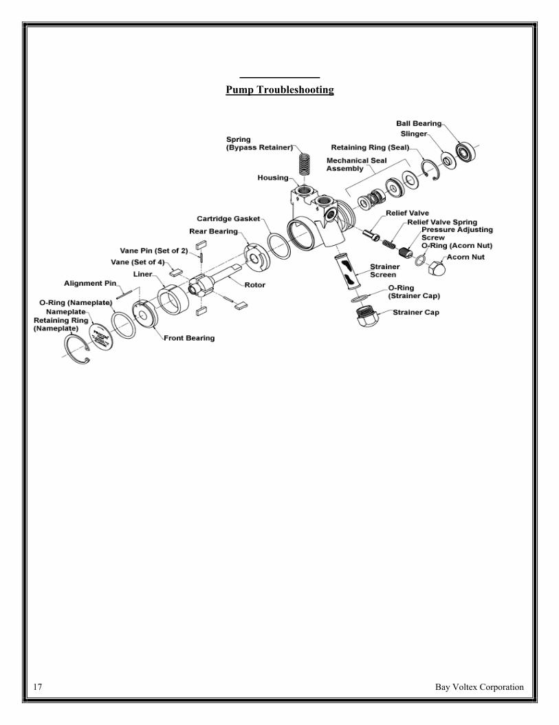
Pump Troubleshooting
Pump Is Working Below Capacity
Possible Cause Possible SolutionInlet is clogged or restrictedInternal strainer is clogged or restricted
Clean out the inlet line. If you have an inlet filter orinternal strainer, clean it (replace it if more than 20%clogged). Do not allow debris to fall into pump fromfilter.
Pump is rotating in the wrong direction Change motor rotation by properly rewiring it.
Low motor RPM Check your motor to make sure it is working properlyand that it is wired for the voltage and frequency (50 or60 HZ) that you are using. (See motor specificationsplate.)
Inside the pump is wearing out, caused by foreign orabrasive materials getting into the pump.
Have the pump rebuilt by PROCON. To prevent futurefailures, make sure you have an adequate filter on theinlet line.
Relief valve setting is incorrect Contact your PROCON representative about having therelief valve reset.
Pump Is Leaking
Possible Cause Possible Solution
Relief valve cap or strainer cap is loose Tighten the cap on the relief valve or strainer.
Relief valve cap or strainer cap O-ring or gasket aredamaged
Replace the damaged O-ring or gasket.Contact PROCON for these parts.
Inlet or outlet port fittings are loose or sealant failed. Apply joint compound or tape and reinstall the fittings. Do not allow sealant to fall into the pump.

16 Bay Voltex Corporation
Pump Troubleshooting
Pump Is Noisy
Possible Cause Possible SolutionInlet is clogged or restricted - internal strainer is cloggedor restricted
Clean out the inlet line. If you have an inlet filter orinternal strainer, clean it (replace it if more than 20%clogged). Do not allow debris to fall into pump fromfilter.
Acorn nut on relief valve or strainer cap is loose. Tighten the acorn nut on the relief valve or the strainercap.
Gasket or O-ring on the acorn nut or strainer cap isdefective.
Replace the gasket or the O-ring on the acorn nut or thestrainer cap. Do not tamper with the relief valve setting. Contact PROCON for parts.
Coupling, mounting bolt, or V-clamp is loose. Turn off the motor and disconnect the power to themotor. Remove the pump from the motor. Then,remount the pump onto the motor, making sure youalign it properly.
The pump and motor are misaligned. Turn off the motor and disconnect the power from themotor. Remove the pump from the motor. Thenremount the pump onto the motor, making sure youalign it properly.
17 Bay Voltex Corporation
Pump Troubleshooting

18 Bay Voltex Corporation
Pump Troubleshooting
Mounting Your Pump On A 48YZ Frame Motor
After you have examined your pump for damage, follow these steps.
1. Make sure motor is electrically disconnected andcannot accidentally turn on.
2. Slip the V-band onto the motor ring flange.
3. Mount the pump to the motor by inserting the tang(shaft) of the pump into the slot on the motor.
4. Rotate the pump to orient theinlet / outlet ports as desired.
5. Make sure the ring flanges on the pump and on themotor are properly engaged and flush against oneanother.
You Should Have These Parts
Clamp-On PROCON Pump
V-Band Clamp
48YZFrame Motor
Mounting
Order
6. Make sure the clamp is fully seated around theentire circumference of the pump and motor flanges.

19 Bay Voltex Corporation
7. Tighten the V-band clamp using 15 to 30 inch-pounds of torque.
NOTE: Do not over tighten the clamp. The V-band clamp is designed to support the pump and fittings only. Loads caused by rigid plumbing or heavy attachments may result in misalignment.
4.42 GPM Pump CurveOption D2 or D4

Standard Pump 2.2 GPM Pump Curve
Positive Displacement Type Pump


![GMW vs. Yao? E cient Secure Two-Party Computation with Low … · 2013. 3. 28. · 2.2.2 GMW Protocol [11,12]. In the GMW protocol two parties interac-tively compute a function using](https://img.pdfslide.us/doc/110x75/61493df6080bfa6260147bfe/gmw-vs-yao-e-cient-secure-two-party-computation-with-low-2013-3-28-222.jpg)