Embed Size (px)
Citation preview
fu'AIR COOLED
LIQUID CHILLERSFOR OUTDOOR INSTALLATION
SERIES CGA . .NOMINAL REFRIGERATION CAPACITIES FROM 309 TO 562 KW
Selection DataÍ50 Hzl
ERTA/SD6-E
GUIDE TO SELECTIONThe capacity table shows the capacity data for the mostÍrequently required conditions. For other conditionswithin the range oÍ the table, direct interpolation mav beused. For conditions not contained in the table. coniactyour local Trane Sales OÍÍice for assistance.To select an Air Cooled WaterChil lertheÍoltowing Íactorsmust be known :1. Design capacity (kW)2. Design chil led water temperature (oC)3. Design temperature drop through the chil ler ("C)4. Design chil led water Í low rate (l i tre,/sec)5. Design ambient air temperature (.C)
When any two factors of (1), (3) and (4) are known, thethird can be calculated using the Íormula :
GENERAL NOTES
1. The ratings are based on chil lerswith standard compo-nents. For particular conditions, certain non-standardcomponent combinations are possible. Contact yourlocal Trane Sales OÍÍice for assistance in selection.
2. The capacity ratings are applicabte for à temperaluredrop within the range 4 to 8.C except as l imited by themaximum or minimum water Ílow rates as indicated byevaporator hydraulic resistance table (Table 5).
3. Compressor kW input Í igures do not inc lude condenserfan motor power input. Refer to Table 1.
4. Ratings are based on fouling Íactor of 0.035 mzKlkW inthe evaporator (commercially clean tubes).
Correction factors for other Íoulino Íactors are shownin Table 4.
Chil led water f low = 0.239 x kW reÍr. = (l/s)temp. drop EVP ("C)
Once lhe design Ílow has been determined it should bemaintained at all t imes Quring chil ler operation, otherwisechiller freeze-up and failure may occur.
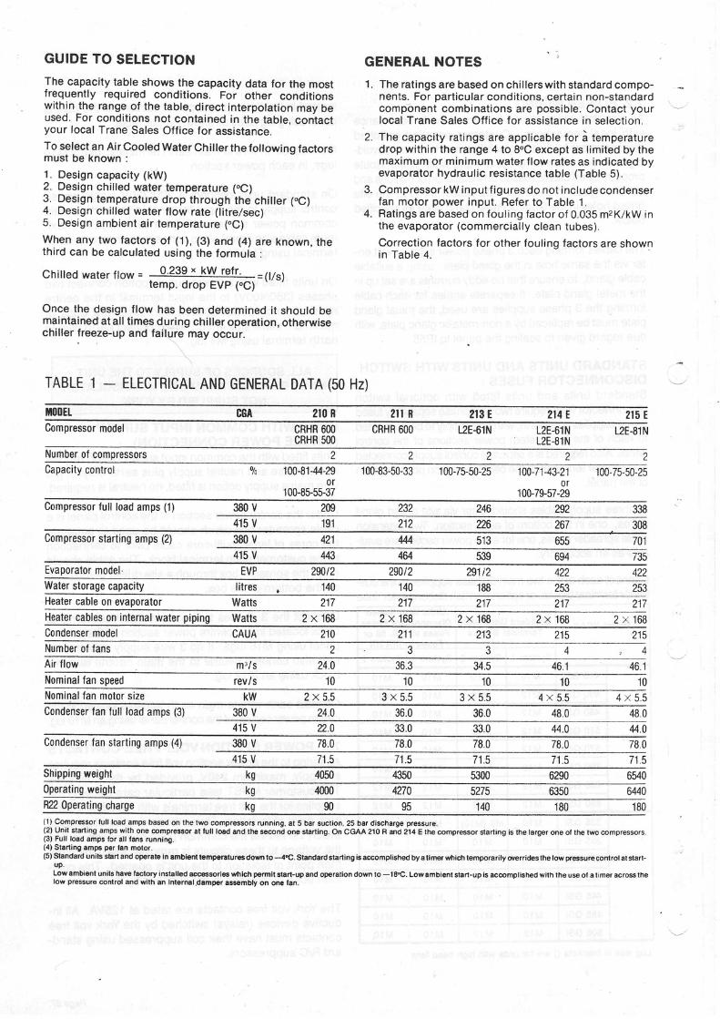
ïABLE 1 - ELECTRICAL AND GENERAL DATA (50 Hz)
ilt00Et- 88À 2t0 R z i lR 2t3 t 214 E 215 ECompressor model CRHR 6M
CRHR 5OOCRHR 600 uE-61N L2E-61N
LzE-81N12E.81 N
Number oÍ comoressorsCapacity control 100-81-44-29
100-85-55-37
100-83-50-33 100-75-50-25 100:71-43-21 100-75-50-250r
100-7$57-29Compressor Íull load amps (1) 380 V 33829226209
30826722621219.1232
415 VCompressor startíng amps (2) 380 V 7416555 1 3u4421
735694539464443415 VFvaporator model EVP 2Wt2 zvutz 291t2 4224tt
Water storage capacity 188140140l itres 9qL
Heater cable on evaporator Watts 217217217217217Healer cables on internal water piping Watts 2 x 1 6 8 2 x 1 6 8 2 x 1 6 8 2 x 1 6 8 2 x 1 6 8
l l at t Jz t J2112't0CAUACondenser modelNumber oí ÍansAir Ílow m3/s 24.0 36.3 46.1A À 134.5Nominal Ían speed rev/s 1010101010Nominal Ían motor size kw 2 x 5 . 5 3 x 5 " 5 3 x 5 . 5 4 x 5 . 5 4 x 5 . 5Condenser Ían Íull toad amps (3) 380 V 24.0 36.0 36.0 48.0 48.0
4't5 V n.a 33.0 33.0 44.044.0Condenser Ían starting amps (4) 380 V 78.0 /8.078.0
71.578.0 78.0
415 V 7'1.5 71.5 71.5 7'l E,
Shipping weighl kg 4050 4f50 5300 6290 65400perating weighl 644042704000kg 5275 6350R22 Operating charge( l ) CompÍessoÍ full ,oad amps based on the lwo comprêssors running, al 5 bar suction, 25 baí discharge pressure.(2) Unil starting smps with one compÍesaor at tull loSd and the second one slarting. On CGAA 210 R md 214 E thê compÍessoÍ garting is lhe laÍgeí onê ol lhe two compÍBsors.{3} Full load amps íoÍ all íans running.(4) Stsrting amps psr lan motoí.(5)s|and8ÍdUnitsst8ÍtandopeÍateinambienttempsÍal!resdomto_.4"c.standaÍdslartingisaccomp|i9hedbyaliÍlGís,hichtêmporari|yo'e
uP.Lowambiant unils hav€ Íactor instatlad aec€esoÍiss which p€Ímil slaÍl-up and operation down to -18"C. Lowambisnt staÍt-up is accomplished wilh the use oÍ a timer acÍoss thelow pÍossuÍs contÍol and with an internal.damper assêmbly on onê tan.
'180r801409590kg
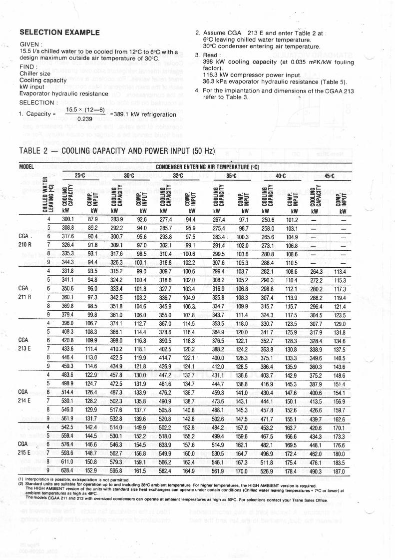
SELECTION EXAMPLEGIVEN :15.5 l/s chil led water to be cooled from 12"C to 6.C with adesign maximum outside air temperature oÍ 30oG.F I N D :Chi l ler s izeCooling capacitykW inputEvaporator hydraulic resistance
S E L E C T I O N :1 c c Y ( 1 2 _ 6 )
1. Capaci ty = ' " " : ^ : :
" ' - =389.1 kW refr igerat ion0.239
TABLE 2 _ COOLING CAPACITY AND POWER INPUT (50 Hz)
Assume CGA 213 E and enter Ta6le 2 at6"C leaving chil led water temperature.30oC condenser entering air temperature.
Read :398 kW cooling capacity (at 0.035 mzKlkW foutingfactor).116.3 kW compressor power input .36.3 kPa evaporator hydraulic resistance (Table S).For the implantat ion and d imensions oÍ the CGAA 213refer to Table 3,
4 .
MO|IEL c01{0E1tsER Et{TERilG AtB TEÍilPERATURE t"Cl45"C35"G32* 4t!{25"C :t0r
g r F= E ^ ' Éd É = Pa < Ê r =3] 'C . l CJ=
k w k w !
crt-
=F ËFo < ( r =CJC-' C- '=
kw kw
c tF= E - . LÉ É = =o < e - -CJC' C.5=
kw ktvË * Ë =kw kw
- È: e - ' É= Í = b= = = ÈE3Ë È5=ktY kw
3e ==E c g = =
== E=Ë= kw
d E
EEkw
300.1 87.9 283.9 2n.4 94.4 267.4 97.1 250,6 101.2308.8 89.2 292.2 94.0 285.7 95.9 275.4 258.0 '103.1
CGA210 R
317.6 300.790.4 97.5 283.4 r 100.3 265.6 104.9326.4 91.8 309.1 97.0 w2.1 99.1 n1.4 1m.0 273.1335.3 93.1 317.6 98.5 310.4 100.6 103.6 108.6280.8344.3 94.4 326.3 t00.1 318.8 fiz.2 s7.6 288.4105.3 't10.5
331.8 93.5 315.2 99.0 309.7 100.6 299.4 103.7 282.1 108.6 26/.3 113.4308.2318.694.8341.1 324.2 100.4 102.0 Í05.2 290.3 110.4 272.2 115.3
CGA211 R
350.6 96.0 333.4 101.8 3r7.7 316.9 106.8 ru8.8 112.1 zffi.2 117.3103.4360.1 97.3 108.3u2.5 103.2 336.7 104.9 325.8 307.4 1'13.9 zffi.2 119.4
345.998.s 351.8 104.6 106.1 334.7 109.9 315.7 115.7 2%.4 121.4379.4 99.8 361.0 106.0 355.0 107.8 u3.7 111.4 n4.3 117.5 304.5 123.5396.0 374.1 112.7 367.0 114.5 353.5 118.0 330.7 123.5 307.7 129.0
120.0408.3 .t08.3 386.1 114.4 116.4 364.9 341.7 125.9 317.9 131.8420.8 398.0 116.3 390.5 118.3 376.5 1n.1 3s2.7 128.3 328.4 134.6CGA
213 E 111 .4 410.2 118.1 402.5 120.2 363.8 130.8 338.9 137.5446.4 113.0 422.5 119.9 414.7 122.1 ' 133.3400.0 126.3 375.1
114.6 434.9 121.8 124.1 412.04m.9 386.4128.5 135.9 360.3 143.6483.6 122.9 457.8 130.0 447.2 132.7 43't.1 136.6 403.7 375.2 148.6
124.7498.9 472.5 131.9 461.6 |U.7 M4.7 138.8 416.9 145.3 387.9 151.4CGA214 E
514.4 126.4 487 "3 133.9 476.2 1ffi.7 459.3 141.0 147.6 400.6 '154.1
530.1 128.2 r35.8 413.5473.6138.7490.9 143.1 444.1 150.1 156.9546.0 129.9 517.6 137.7 505.8 159.7488.1 145.3140.8 457.8 152.6 426.6s1.9 131.7 532.8 r39.6 520.8 142.8 5tr2.6 147.5 471.7 155.1 439.7 162.6542.5 142.4 514.& 149.9 592.2 152.8 4U.2 Í57.0 420.6 170.1559.4 144.5 530.1 152.2 499.4155.2518.0 159.6 467.5 166.6 434.3 173.3576.4 546.3 tí4.5 633.9 157.6 5't4.9 162.'t M.1 176.6CGA ),
215 E 593.6 148.7 ffi27
628.4 152.9 595.8 í61.5 582.4 18t.9 561.9 526.9 178.4 187.0(1) lnterpolation is pcsible. extrapotation is not pêrmilted.(21 Slandard units are suilable for opeíaiion up io and including 38oC ambient tempoÍalure. For higheÍ tempeÍalws, th€ filGH AMBTENT veÍsion b roqdÍgd.The HIGH AMBIENT veEion oÍ the units with standard size tleal exchangcrs cà oPerate mdeï certain ;onditions (Chilled wateí leavlng tempraturss + 7og or to,veÍ) arambiml tempenluÍes as hioh as 48€.
Themodels CGAA ztt ano it3 with wersized condenseÍs can opoÍale at ambiênt lemp€Íaluras as high as 5eC. FoÍ sgletioG contact youí Trane sales otÍice.
170.0 490.3
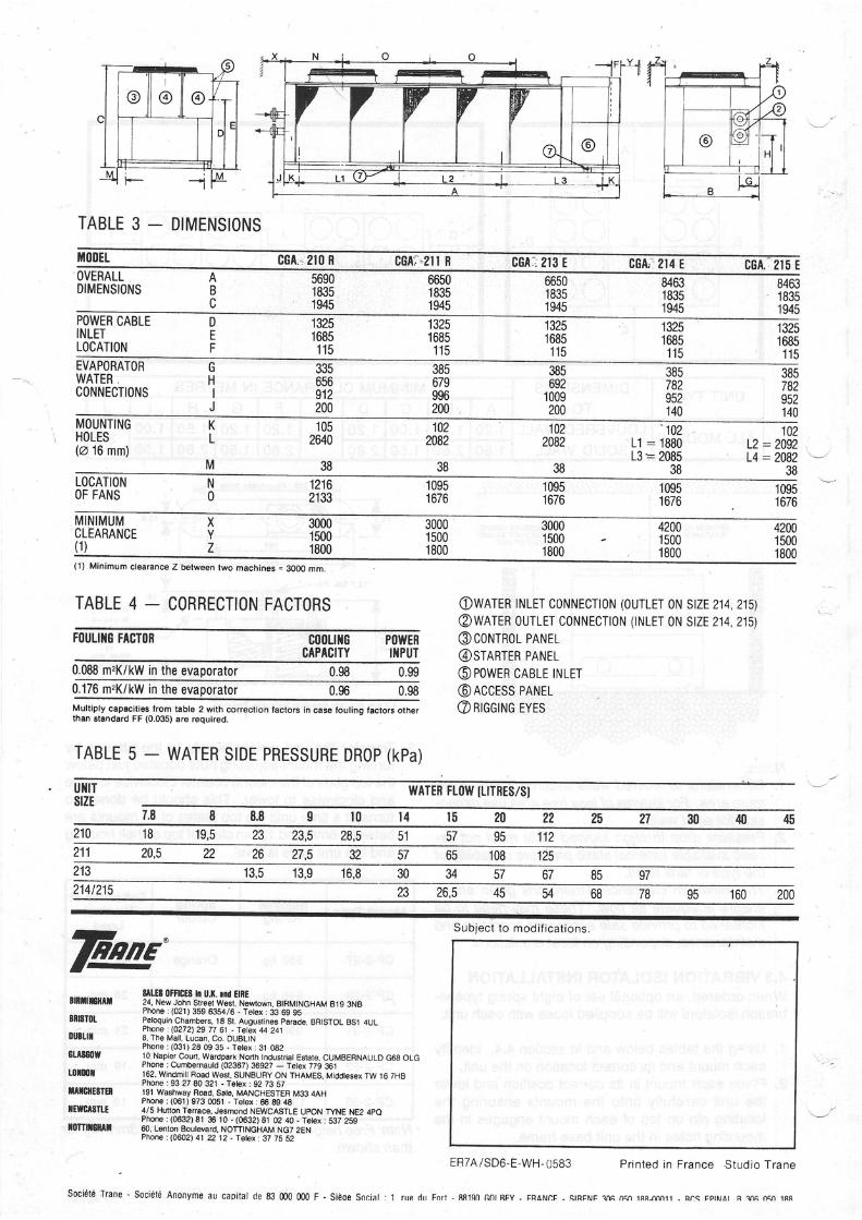
TABLE 3 - DIMENSIONS
Míll]EL cGA* 2t 0 R cGAi.zll R CGA:;213 E 8GÀr 214 E CGA, 2I5 E84631835'1945
846318351945
665018351945
665018351945
569018351945
AB
OVERALLDIMENSIONS
POWER CABLEINLETLOCATION
132516851 1 5
DEF
13251685't15
132516851 t 5
13251685'115
132516851 1 5385782
140
385782952140
385692
1009200
385679996200
33s656912200
HIJ
EVAPORATORWATER,CONNECTIONS
MOUNÏINGHOLES(@ 16 mm)
KL
M
1022082
38
1022082
38
1052M0
38
'102
L l :1880L3 = 2085
38
102L2:2092L4:2082
JO
LOCATIONOF FANS
Nn
12162133
1 0951676
10951 676
1095t o / o
10951676
4200't5001800
300015001800
30001 5001800
300015001800
420015001 800
XYZ
MINIMUMCLEARANCE(1 )
FÍ)ULI]IG FACTÍIR
(1) Minimum clearance Z between two machines = 3OOO mm.
TABLE 4 _ CORRECTION FACTORS OWATEB INLET CIINNEcTION (OUTLET ON SIZE 214,215)@wATER oUTLET coNNECTIoN (INLET 0N stzEzi4,zls)@corurnol pnrurt.@srenrun pnul@powrn cABLE TNLET@ACCESS PANEL@ ntee rue rvrs
c00LrÍrGCAPACITY
PÍ)WEF[{PUT
0.088 m.K/kW in the evaporator0.176 m,K/kW in the evaporatorMultiply capacities Írom table 2 with corr€ction tactoÍs in case Íouling factors otherthan standa.d FF (0.035) aÍe requiÍed.
TABLE 5 - WATER SIDE PRESSURE DROP (KPa)
0.98 0.990.980.96
ut{rTsrzE I,ATER FL(]IV ÍLITRES/SI
45403027252220l 5l 4l 08.87,8
11295575128,5IJ19,5í 8210 23,512510865573226éz20,5211 27,5
07R(6757u?n16,8Í3,913,5213
200160957868u45' A E214 t215
Subjec t to mod i Í i ca t ions .
fut'8rBilt8[tt
rilsT0t
ouilu
8U860W
uxmtilTrufiE8TER
ffTMSTLE
r0TTil6mil
8llES 0tFlGES In U.|(. ||d E|RE24, New John StÍeei West, Newtown, BtHMtNcHAM Bt9 3NBPhore : (021) 359 6354/6 - Tetex: 33 69 95Peloquin Chambers, 18 St. Augustines paíade, BRISTOL BSt 4ULPhone . (0272\ 29 n d - fetex 44 248, The Mall, Lucan. Co. DUBLTNPhone: (031) 28 09 35 - ïetex:31 08210 Napier Court, WaÍdpark Norih Industriat Eslate. CUMBERNAULD G68 OLGPhone : Cumb€rnautd (02367) 36927 - Telex 779 361162. Windmill Road Wesl. SUNBURY ON THAMES, Middtesex TW 16 7HBPhone :93 27 80 321 - ïetex : 92 73 57191 Washway RGd, Sale, MANCHESTER M33 4AHPhone : (061) 973 m51 - Ietex:66 89 4g4/5 Hunon Terrace, Jesmond NEWCASTLE UPON TYNE NE2 4pOPhone : {0632) 81 S 10 - (0632) 8t 02 40 - Tetex : S37 2S960. Lenton Boulevafd, NOTTINGHAM NG7 2ENPhone : (0602) 41 22 12 - Tetex : 37 75 52
ERTAi SD6-E.WH-0583 Printed in France .Studio Trane
Société Trane - Société Anonyme au caoital de m m0 000 F - Sièoe Sociat : 1 nre di l For l - 88190 Gnl RFY - FÊÀNI]F - STRFNF 1n6 n5n 18RJrvt11 - Rnq FptNAt R lnA n6n 1RR