Embed Size (px)
Citation preview

ButtweldingEnds

CONTENTS
Foreword . . . . . . . . . . . . . . . . . . . . . . . . . . . . . . . . . . . . . . . . . . . . . . . . . . . . . . . . . . . . . . . . . . . . . . . . . . . . . . ivCommittee Roster . . . . . . . . . . . . . . . . . . . . . . . . . . . . . . . . . . . . . . . . . . . . . . . . . . . . . . . . . . . . . . . . . . . . . vCorrespondence With the B16 Committee . . . . . . . . . . . . . . . . . . . . . . . . . . . . . . . . . . . . . . . . . . . . . . viSummary of Changes . . . . . . . . . . . . . . . . . . . . . . . . . . . . . . . . . . . . . . . . . . . . . . . . . . . . . . . . . . . . . . . . . . vii
1 Scope . . . . . . . . . . . . . . . . . . . . . . . . . . . . . . . . . . . . . . . . . . . . . . . . . . . . . . . . . . . . . . . . . . . . . . . . . . . . . . 1
2 Transition Contours . . . . . . . . . . . . . . . . . . . . . . . . . . . . . . . . . . . . . . . . . . . . . . . . . . . . . . . . . . . . . . . . . 1
3 Welding Bevel Design . . . . . . . . . . . . . . . . . . . . . . . . . . . . . . . . . . . . . . . . . . . . . . . . . . . . . . . . . . . . . . . 2
4 Preparation of Inside Diameter of Welding End. . . . . . . . . . . . . . . . . . . . . . . . . . . . . . . . . . . . . . . . 2
5 Tolerances . . . . . . . . . . . . . . . . . . . . . . . . . . . . . . . . . . . . . . . . . . . . . . . . . . . . . . . . . . . . . . . . . . . . . . . . . . 3
Figures1 Maximum Envelope for Welding End Transitions . . . . . . . . . . . . . . . . . . . . . . . . . . . . . . . . . . . 42 Bevels for Wall Thickness Over 3 mm (0.12 in.) to 22 mm (0.88 in.), Inclusive . . . . . . . . 53 Weld Bevel Details for Wall Thickness Over 22 mm (0.88 in.) . . . . . . . . . . . . . . . . . . . . . . . . 64 Weld Bevel Details for GTAW Root Pass [Wall Thickness Over
3 mm (0.12 in.) to 10 mm (0.38 in.), Inclusive] . . . . . . . . . . . . . . . . . . . . . . . . . . . . . . . . . . . . 75 Weld Bevel Details for GTAW Root Pass [Wall Thickness Over
10 mm (0.38 in.) to 25 mm (1.0 in.), Inclusive] . . . . . . . . . . . . . . . . . . . . . . . . . . . . . . . . . . . . 76 Weld Bevel Details for GTAW Root Pass [Wall Thickness Over
25 mm (1.0 in.)] . . . . . . . . . . . . . . . . . . . . . . . . . . . . . . . . . . . . . . . . . . . . . . . . . . . . . . . . . . . . . . . . 8
Table1 Dimensions of Welding Ends . . . . . . . . . . . . . . . . . . . . . . . . . . . . . . . . . . . . . . . . . . . . . . . . . . . . . . . 9
Mandatory AppendicesI Inch Table . . . . . . . . . . . . . . . . . . . . . . . . . . . . . . . . . . . . . . . . . . . . . . . . . . . . . . . . . . . . . . . . . . . . . . . . . 13II References . . . . . . . . . . . . . . . . . . . . . . . . . . . . . . . . . . . . . . . . . . . . . . . . . . . . . . . . . . . . . . . . . . . . . . . . . 18
Nonmandatory AppendixA Quality System Program . . . . . . . . . . . . . . . . . . . . . . . . . . . . . . . . . . . . . . . . . . . . . . . . . . . . . . . . . . . 19
--`,,```,,,,````-`-`,,`,,`,`,,`---
BUTTWELDING ENDS
1 SCOPE
1.1 General
This Standard covers the preparation of buttweldingends of piping components to be joined into a pipingsystem bywelding. It includes requirements for weldingbevels, for external and internal shaping of heavy-wallcomponents, and for preparation of internal ends(including dimensions and tolerances). Coverageincludes preparation for joints with the following:
(a) no backing rings(b) split or noncontinuous backing rings(c) solid or continuous backing rings(d) consumable insert rings(e) gas tungsten arc welding (GTAW) of the root passDetails of preparation for any backing ring must be
specified when ordering the component.
1.2 Application
This Standard applies to any metallic materials forwhich a welding procedure can be satisfactorilyqualified but does not prescribe specific welding pro-cesses or procedures. Unless otherwise specified by thepurchaser, it does not apply to welding ends conformingto ASME B16.5, B16.9, or B16.47.
1.3 Relevant Units
This Standard states values in both SI (Metric) andU.S. Customary units. These systems of units are to beregarded separately as standard. Within the text, theU.S. Customary units are shown in parentheses or in aseparate table that appears in Mandatory Appendix I.The values stated in each system are not exact equiva-lents; therefore, it is required that each system of unitsbe used independently of the other. Combining valuesfrom the two systems constitutes nonconformance withthe Standard.
1.4 Size
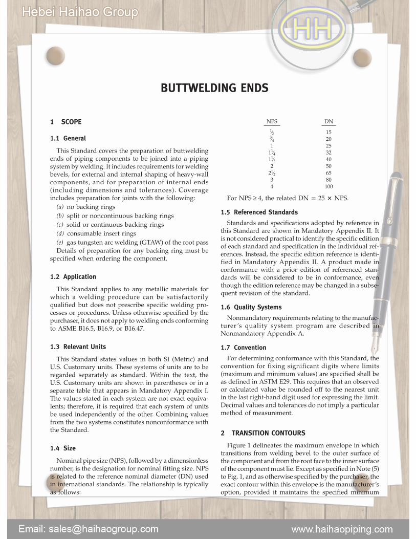
Nominal pipe size (NPS), followed by a dimensionlessnumber, is the designation for nominal fitting size. NPSis related to the reference nominal diameter (DN) usedin international standards. The relationship is typicallyas follows:
NPS DN
1⁄2 153⁄4 201 2511⁄4 3211⁄2 402 5021⁄2 653 804 100
For NPS ≥ 4, the related DN p 25 � NPS.
1.5 Referenced Standards
Standards and specifications adopted by reference inthis Standard are shown in Mandatory Appendix II. Itis not considered practical to identify the specific editionof each standard and specification in the individual ref-erences. Instead, the specific edition reference is identi-fied in Mandatory Appendix II. A product made inconformance with a prior edition of referenced stan-dards will be considered to be in conformance, eventhough the edition reference may be changed in a subse-quent revision of the standard.
1.6 Quality Systems
Nonmandatory requirements relating to the manufac-turer ’s quality system program are described inNonmandatory Appendix A.
1.7 Convention
For determining conformance with this Standard, theconvention for fixing significant digits where limits(maximum and minimum values) are specified shall beas defined in ASTM E29. This requires that an observedor calculated value be rounded off to the nearest unitin the last right-hand digit used for expressing the limit.Decimal values and tolerances do not imply a particularmethod of measurement.
2 TRANSITION CONTOURS
Figure 1 delineates the maximum envelope in whichtransitions from welding bevel to the outer surface ofthe component and from the root face to the inner surfaceof the componentmust lie. Except as specified inNote (5)to Fig. 1, and as otherwise specified by the purchaser, theexact contour within this envelope is the manufacturer’soption, provided it maintains the specified minimum

wall thickness, has no slopes steeper than those indi-cated for the respective regions, and includes the propersurface for backing rings if specified.
3 WELDING BEVEL DESIGN
3.1 Bevels for Other Than GTAW Root Pass
(a) Components having nominal wall thicknesses of3 mm (0.12 in.) and less shall have ends cut square orslightly chamfered.
(b) Components having nominal wall thicknessesover 3 mm (0.12 in.) to 22 mm (0.88 in.) inclusive shallhave single angle bevels as illustrated in Fig. 2.
(c) Components having nominal wall thicknessesgreater than 22mm (0.88 in.) shall have compound anglebevels as illustrated in Fig. 3.
3.2 Bevels for GTAW Root Pass
(a) Components having nominal wall thicknesses of3 mm (0.12 in.) and less shall have ends cut square orslightly chamfered.
(b) Components having nominal wall thicknessesover 3 mm (0.12 in.) to 10 mm (0.38 in.) inclusive shallhave 371⁄2-deg ± 21⁄2-deg bevels or slightly concave bevels(see Fig. 4).
(c) Components having nominal wall thicknessesover 10 mm (0.38 in.) to 25 mm (1.0 in.) inclusive shallhave bevels as shown in Fig. 5.
(d) Components having nominal wall thicknessesgreater than 25 mm (1.0 in.) shall have bevels as shownin Fig. 6.
3.3 Outside Diameter at Welding Ends
Dimension A shall be either that specified in theapplicable component standard or that specified in thepurchaser’s component specification. In the absenceof a requirement for dimension A in a component stan-dard or a purchaser’s specification, the values for dimen-sion A in Table 1 or Table I-1 may be used.
4 PREPARATION OF INSIDE DIAMETER OFWELDING END
4.1 General
Preparation of the inside diameter at the end of acomponent shall be in accordancewith one of the follow-ing, as specified by the purchaser:
(a) Components to be welded without backing ringsshall meet the requirements of the standard or specifica-tion for the component.
(b) Components to be welded using split or noncon-tinuous backing rings shall be contouredwith a cylindri-cal surface at the end as shown in Fig. 2, illustration (b)and Fig. 3, illustration (b). If the backing ring contouris other than rectangular, details must be furnished bythe purchaser.
2
(c) Components to be welded using solid or continu-ous backing rings shall be contoured with a cylindricalor tapered surface at the end as specified by the pur-chaser. End preparation is illustrated in Fig. 2, illustra-tion (c) and Fig. 3, illustration (c) for rectangular endsand in Fig. 2, illustration (d) and Fig. 3, illustration (d)for tapered ends.
(d) Components to be welded using consumableinsert rings or GTAW root pass shall be contoured witha cylindrical surface at the end as shown in Figs. 4through 6.
4.2 Dimension C
Values for dimension C shown in Fig. 2, illustrations(c) and (d); Fig. 3, illustrations (c) and (d); and Figs. 5and 6 can be determined by the following equations:
(SI Units)
C p A − O.D. tolerance − 2 � tmin − 0.25 (1)
(U.S. Customary Units)
C p A − O.D. tolerance − 2 � tmin − 0.010 (2)
whereA p specified outside pipe diameter at
welding end (see para. 3.3)O.D. tolerance p undertolerance on the pipe O.D.
from the applicable pipingspecification
tmin p t − manufacturing tolerance forpipe wall thickness per applicablepipe specification, mm (in.)
t p nominal wall thickness of pipe,mm (in.)
0.25 (0.010) p plus machining tolerance onBore C, mm (in.)
Based on tolerances specific to ASTM A106 and A335pipe, including an undertolerance on wall thickness of12.5%, eqs. (1) and (2) can be defined as follows:
(SI Units)
C p A − 0.79 − 2 � 0.875t − 0.25
(U.S. Customary Units)
C p A − 0.031 − 2 � 0.875t − 0.010
Tables 1 and I-1 list the C values for pipe with anundertolerance of 12.5% on wall thickness, includingASTM A106 and A335 pipe, in sizes NPS 2½ throughNPS 48. For pipe with a pipe wall thickness undertoler-ance other than 12.5%, do not use the C data fromTables 1 and I-1 [see para. 4.3(a)].
4.3 Exceptions
(a) For pipe or tubing varying from the ASTM A106and A335 types, having different wall thickness and/or -
-`,,```,,,,````-`-`,,`,,`,`,,`---
outside diameter tolerances (such as forged and boredpipe), the foregoing equations may be inapplicable.Equations (1) and (2) may be used to determine C forthese applications. The purchaser shall specify theC dimension when Tables 1 and I-1 data do not apply.
(b) For components in smaller sizes and lower sched-ule numbers, it may be necessary to deposit weld metalon the inside diameter (I.D.) or use thickerwall materialsin order to machine the backing ring while maintainingrequired wall thickness. This condition may also arisewhen using material whose nominal dimensions indi-cate sufficient metal but whose actual I.D., consideringtolerances, is large enough to require additional metal.
5 TOLERANCES (See Figs. 2, 3, 5, and 6)
5.1 Dimension B
Values for the I.D. at the welding end [seedimension B, Fig. 2, illustrations (a) and (b) and Fig. 3,illustrations (a) and (b)] shall be as specified in the appli-cable standard or specification for the component.
5.2 Welding Bevels, Root Face, and Dimension C
Values of welding bevels, root face, and dimension Cshall be as indicated in Figs. 2 through 6.
3
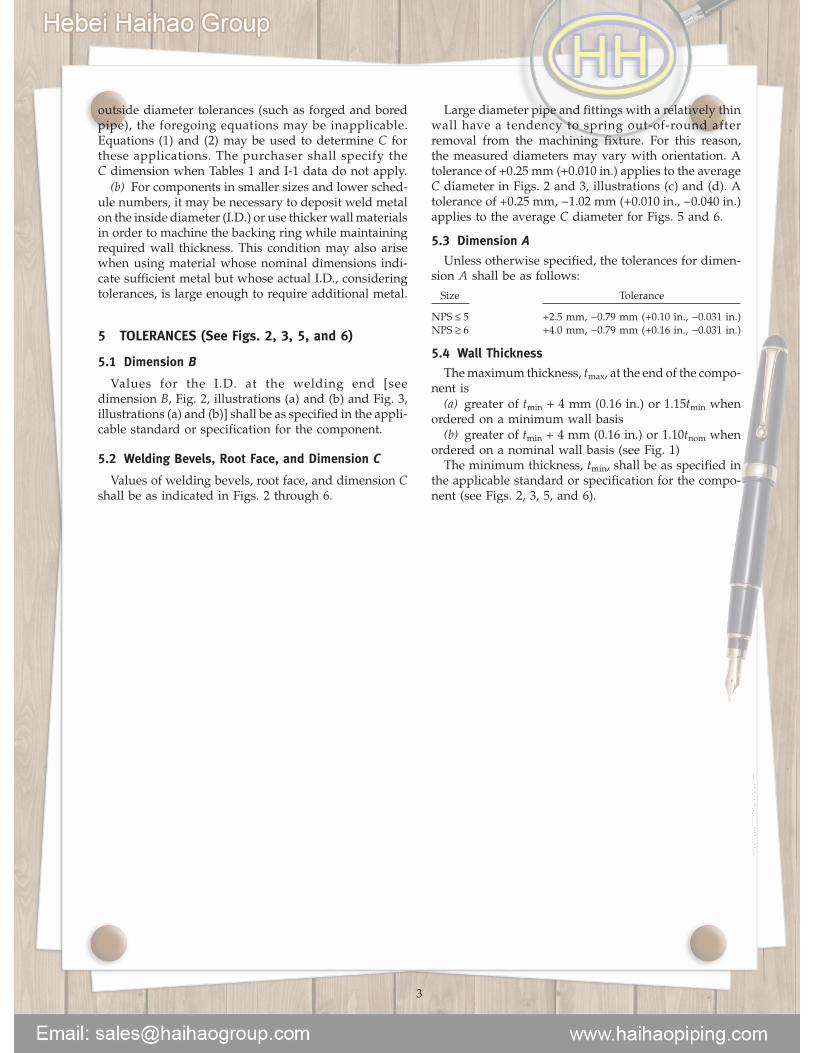
Large diameter pipe and fittings with a relatively thinwall have a tendency to spring out-of-round afterremoval from the machining fixture. For this reason,the measured diameters may vary with orientation. Atolerance of +0.25 mm (+0.010 in.) applies to the averageC diameter in Figs. 2 and 3, illustrations (c) and (d). Atolerance of +0.25 mm, −1.02 mm (+0.010 in., −0.040 in.)applies to the average C diameter for Figs. 5 and 6.
5.3 Dimension A
Unless otherwise specified, the tolerances for dimen-sion A shall be as follows:
Size Tolerance
NPS ≤ 5 +2.5 mm, −0.79 mm (+0.10 in., −0.031 in.)NPS ≥ 6 +4.0 mm, −0.79 mm (+0.16 in., −0.031 in.)
5.4 Wall Thickness
Themaximum thickness, tmax, at the end of the compo-nent is
(a) greater of tmin + 4 mm (0.16 in.) or 1.15tmin whenordered on a minimum wall basis
(b) greater of tmin + 4 mm (0.16 in.) or 1.10tnom whenordered on a nominal wall basis (see Fig. 1)The minimum thickness, tmin, shall be as specified in
the applicable standard or specification for the compo-nent (see Figs. 2, 3, 5, and 6).
--`,,```,,,,````-`-`,,`,,`,`,,`---
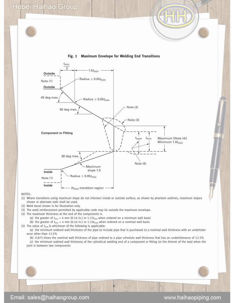
Fig. 1 Maximum Envelope for Welding End Transitions
2tmin transition region
Radius
Maximum slope 1:3
Maximum [Note (4)]Minimum 1.0tmin
1.5tmin
Note (3)
Note (1)
Note (2)
Note (5)
30 deg max.
30 deg max.
45 deg max.
0.05tmin
Radius 0.05tmin
tnom tmin
Inside
Inside
Outside
Outside
Component or Fitting
Note (1)
tmin
2
Radius 0.05tmin
NOTES:(1) Where transitions using maximum slope do not intersect inside or outside surface, as shown by phantom outlines, maximum slopes
shown or alternate radii shall be used.(2) Weld bevel shown is for illustration only.(3) The weld reinforcement permitted by applicable code may lie outside the maximum envelope.(4) The maximum thickness at the end of the components is
(a) the greater of tmin + 4 mm (0.16 in.) or 1.15tmin when ordered on a minimum wall basis(b) the greater of tmin + 4 mm (0.16 in.) or 1.10tnom when ordered on a nominal wall basis
(5) The value of tmin is whichever of the following is applicable:(a) the minimum ordered wall thickness of the pipe to include pipe that is purchased to a nominal wall thickness with an undertoler-
ance other than 12.5%(b) 0.875 times the nominal wall thickness of pipe ordered to a pipe schedule wall thickness that has an undertolerance of 12.5%(c) the minimum ordered wall thickness of the cylindrical welding end of a component or fitting (or the thinner of the two) when the
joint is between two components
4

Fig. 2 Bevels for Wall Thickness Over 3 mm (0.12 in.) to 22 mm (0.88 in.), Inclusive
13 (0.5) min.
Note (2)
30 deg max.
Note (1) 1.6 ± 0.8 (0.06 ± 0.03)
1.6 ± 0.8 (0.06 ± 0.03)
37.5 deg ± 2.5 deg
BA
(a) Welding End Detail for Joint Without Backing Ring (b) Welding End Detail for Joint Using Split
Rectangular Backing Ring
(d) Welding End Detail for Joint Using Continuous
Tapered Backing Ring
(c) Welding End Detail for Joint Using Continuous
Rectangular Backing Ring
BA
37.5 deg ± 2.5 deg
30 deg max.
30 deg max.10 deg
1.6 ± 0.8 (0.06 ± 0.03)
13 (0.5) min.
1.6 ± 0.8 (0.06 ± 0.03)
6 (0.22) min.
+0.25, �0 (+0.010, �0)
37.5 deg ± 2.5 deg
A
A
37.5 deg ± 2.5 deg
Note (2)Note (2)
C+0.25, �0 (+0.010, �0)
C
GENERAL NOTES:(a) Broken lines denote maximum envelope for transitions from welding bevel and root face into body of component. See Fig. 1 for
details.(b) See section 5 for tolerances other than those given in these illustrations.(c) Purchase order must specify contour of any backing ring to be used.(d) Linear dimensions are in millimeters with inch values in parentheses.
NOTES:(1) Internal surface may be as-formed or machined for dimension B at root face. Contour within the envelope shall be in accordance with
section 2.(2) Intersections should be slightly rounded.
5
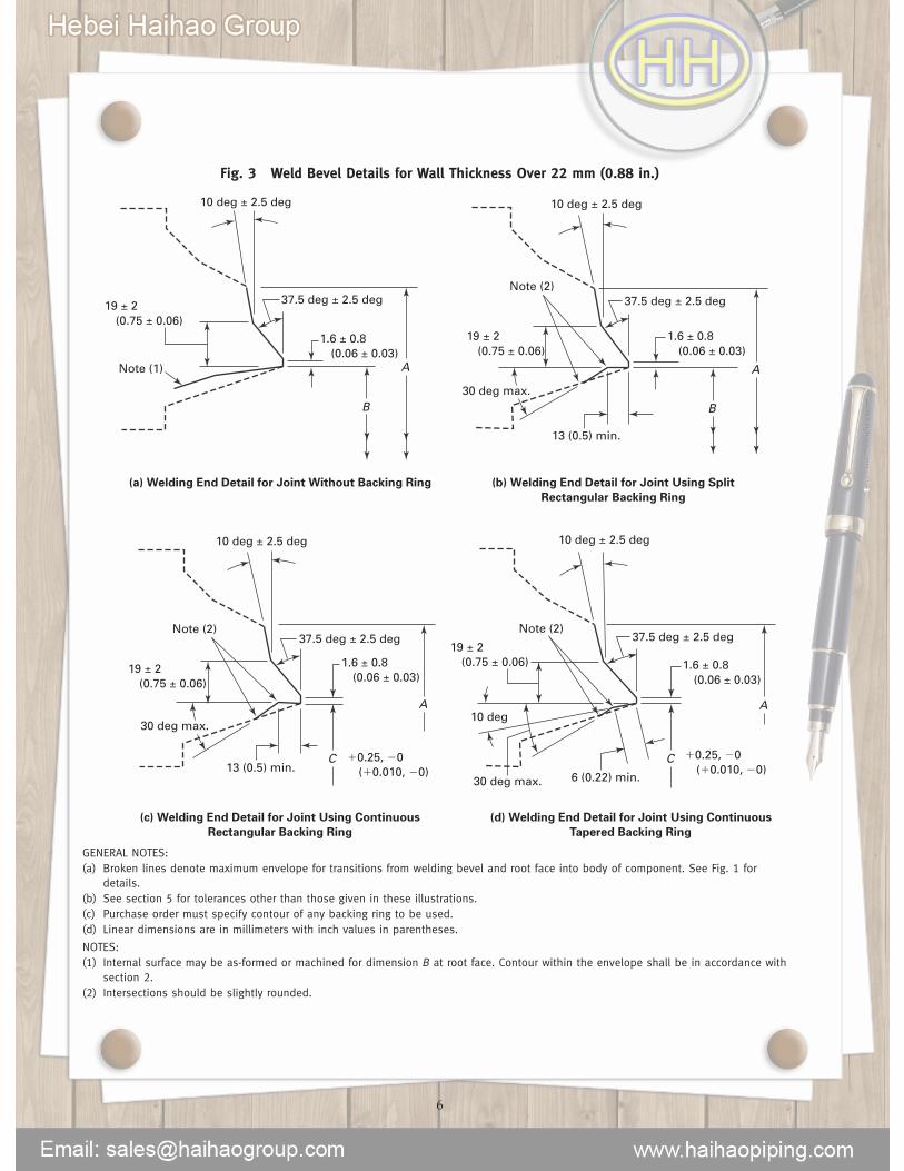
Fig. 3 Weld Bevel Details for Wall Thickness Over 22 mm (0.88 in.)
13 (0.5) min.
Note (2)
30 deg max.
Note (1)
1.6 ± 0.8 (0.06 ± 0.03)
19 ± 2 (0.75 ± 0.06)
1.6 ± 0.8 (0.06 ± 0.03)
10 deg ± 2.5 deg 10 deg ± 2.5 deg
37.5 deg ± 2.5 deg19 ± 2 (0.75 ± 0.06)
B
A
(a) Welding End Detail for Joint Without Backing Ring (b) Welding End Detail for Joint Using Split
Rectangular Backing Ring
B
A
30 deg max.
37.5 deg ± 2.5 deg
6 (0.22) min.
Note (2)
30 deg max.
10 deg
Note (2)
1.6 ± 0.8 (0.06 ± 0.03)
�0.25, �0 (�0.010, �0)
�0.25, �0 (�0.010, �0)
19 ± 2 (0.75 ± 0.06) 1.6 ± 0.8
(0.06 ± 0.03)
10 deg ± 2.5 deg 10 deg ± 2.5 deg
37.5 deg ± 2.5 deg
13 (0.5) min.
19 ± 2 (0.75 ± 0.06)
C
A
(c) Welding End Detail for Joint Using Continuous
Rectangular Backing Ring
(d) Welding End Detail for Joint Using Continuous
Tapered Backing Ring
C
A
37.5 deg ± 2.5 deg
GENERAL NOTES:(a) Broken lines denote maximum envelope for transitions from welding bevel and root face into body of component. See Fig. 1 for
details.(b) See section 5 for tolerances other than those given in these illustrations.(c) Purchase order must specify contour of any backing ring to be used.(d) Linear dimensions are in millimeters with inch values in parentheses.
NOTES:(1) Internal surface may be as-formed or machined for dimension B at root face. Contour within the envelope shall be in accordance with
section 2.(2) Intersections should be slightly rounded.
6
--`,,```,,,,````-`-`,,`,,`,`,,`---

Fig. 4 Weld Bevel Details for GTAW Root Pass[Wall Thickness Over 3 mm (0.12 in.) to 10 mm
(0.38 in.), Inclusive]
Alternate
37.5 deg ± 2.5 deg
1.6 ± 0.8 (0.06 ± 0.03)
GENERAL NOTES:(a) This detail applies for gas tungsten arc welding (GTAW) of the
root pass where nominal wall thickness is over 3 mm(0.12 in.) to 10 mm (0.38 in.), inclusive.
(b) Linear dimensions are in millimeters with inch values inparentheses.
Fig. 5 Weld Bevel Details for GTAW Root Pass[Wall Thickness Over 10 mm (0.38 in.) to 25 mm (1.0 in.), Inclusive]
30 deg max.
5 (0.19) min.
5 (0.19) R
Note (1)
30 deg max.
Note (1)
3 (0.12)
2 ± 0.4 (0.078 ± 0.016)
2 ± 0.4 (0.078 ± 0.016)
�0.25, �1.02 (�0.010, �0.040)
�0.25, �1.02 (�0.010, �0.040)
20 deg ± 2.5 deg
5 (0.19) min.C
A
Type A Type B
C
A
20 deg ± 2.5 deg
0 to 2 (0.06)
GENERAL NOTES:(a) This detail applies for gas tungsten arc welding (GTAW) of the root pass where nominal wall thickness is over 10 mm (0.38 in.) to
25 mm (1.0 in.), inclusive.(b) Broken lines denote maximum envelope for transitions from welding groove and land into body of component. See Fig. 1 for
details.(c) See section 5 for tolerances other than those given in these illustrations.(d) Linear dimensions are in millimeters with inch values in parentheses.
NOTE:(1) Inside corners should be slightly rounded.
7
--`,,```,,,,````-`-`,,`,,`,`,,`---
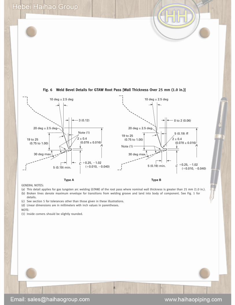
Fig. 6 Weld Bevel Details for GTAW Root Pass [Wall Thickness Over 25 mm (1.0 in.)]
30 deg max.
Note (1)
Note (1)
3 (0.12)
2 ± 0.4 (0.078 ± 0.016)
�0.25, �1.02 (�0.010, �0.040)
10 deg ± 2.5 deg
20 deg ± 2.5 deg
19 to 25 (0.75 to 1.00)
5 (0.19) min.C
A
Type A Type B
30 deg max.
5 (0.19) R
0 to 2 (0.06)
2 ± 0.4 (0.078 ± 0.016)
�0.25, �1.02 (�0.010, �0.040)
10 deg ± 2.5 deg
20 deg ± 2.5 deg
19 to 25 (0.75 to 1.00)
5 (0.19) min. C
A
GENERAL NOTES:(a) This detail applies for gas tungsten arc welding (GTAW) of the root pass where nominal wall thickness is greater than 25 mm (1.0 in.).(b) Broken lines denote maximum envelope for transitions from welding groove and land into body of component. See Fig. 1 for
details.(c) See section 5 for tolerances other than those given in these illustrations.(d) Linear dimensions are in millimeters with inch values in parentheses.
NOTE:(1) Inside corners should be slightly rounded.
8--`,,```,,,,````-`-`,,`,,`,`,,`---
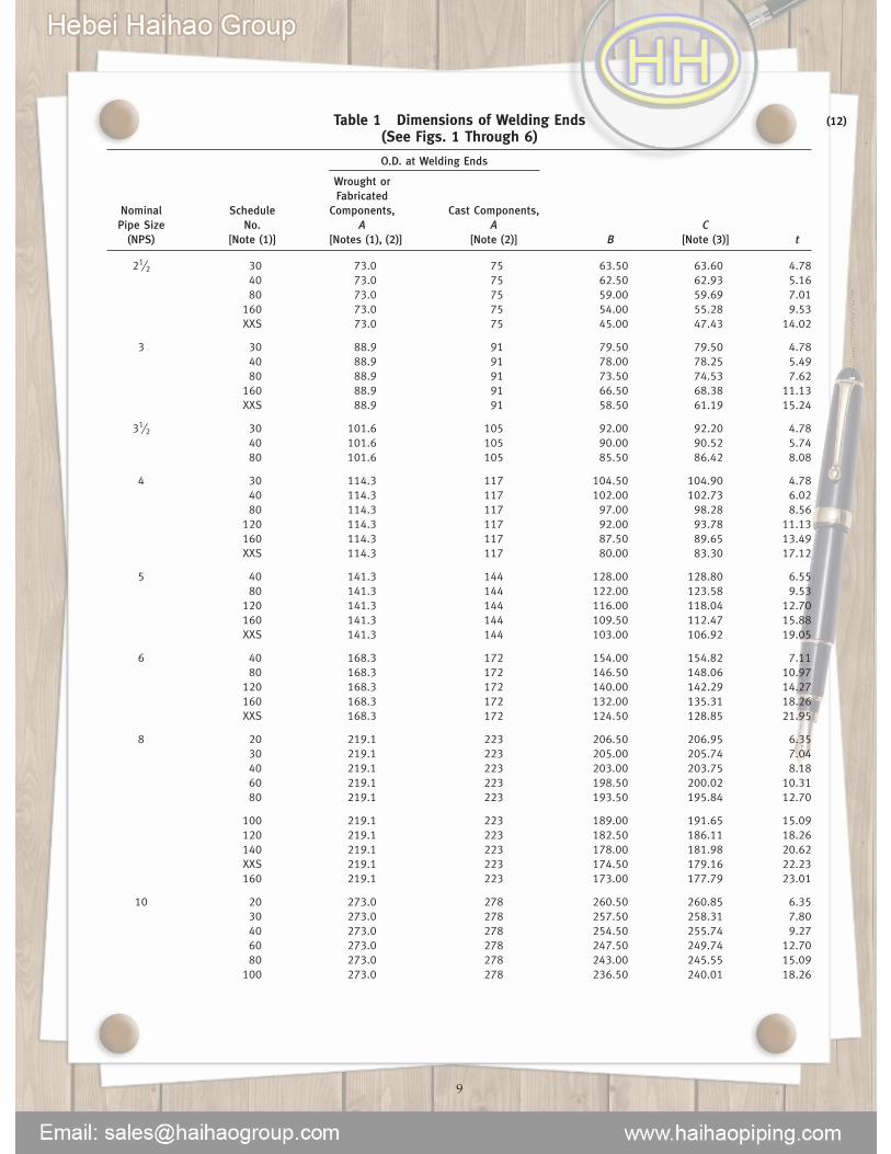
Table 1 Dimensions of Welding Ends(See Figs. 1 Through 6)
O.D. at Welding Ends
Wrought orFabricated
Nominal Schedule Components, Cast Components,Pipe Size No. A A C
(NPS) [Note (1)] [Notes (1), (2)] [Note (2)] B [Note (3)] t
21⁄2 30 73.0 75 63.50 63.60 4.7840 73.0 75 62.50 62.93 5.1680 73.0 75 59.00 59.69 7.01160 73.0 75 54.00 55.28 9.53XXS 73.0 75 45.00 47.43 14.02
3 30 88.9 91 79.50 79.50 4.7840 88.9 91 78.00 78.25 5.4980 88.9 91 73.50 74.53 7.62160 88.9 91 66.50 68.38 11.13XXS 88.9 91 58.50 61.19 15.24
31⁄2 30 101.6 105 92.00 92.20 4.7840 101.6 105 90.00 90.52 5.7480 101.6 105 85.50 86.42 8.08
4 30 114.3 117 104.50 104.90 4.7840 114.3 117 102.00 102.73 6.0280 114.3 117 97.00 98.28 8.56120 114.3 117 92.00 93.78 11.13160 114.3 117 87.50 89.65 13.49XXS 114.3 117 80.00 83.30 17.12
5 40 141.3 144 128.00 128.80 6.5580 141.3 144 122.00 123.58 9.53120 141.3 144 116.00 118.04 12.70160 141.3 144 109.50 112.47 15.88XXS 141.3 144 103.00 106.92 19.05
6 40 168.3 172 154.00 154.82 7.1180 168.3 172 146.50 148.06 10.97120 168.3 172 140.00 142.29 14.27160 168.3 172 132.00 135.31 18.26XXS 168.3 172 124.50 128.85 21.95
8 20 219.1 223 206.50 206.95 6.3530 219.1 223 205.00 205.74 7.0440 219.1 223 203.00 203.75 8.1860 219.1 223 198.50 200.02 10.3180 219.1 223 193.50 195.84 12.70
100 219.1 223 189.00 191.65 15.09120 219.1 223 182.50 186.11 18.26140 219.1 223 178.00 181.98 20.62XXS 219.1 223 174.50 179.16 22.23160 219.1 223 173.00 177.79 23.01
10 20 273.0 278 260.50 260.85 6.3530 273.0 278 257.50 258.31 7.8040 273.0 278 254.50 255.74 9.2760 273.0 278 247.50 249.74 12.7080 273.0 278 243.00 245.55 15.09100 273.0 278 236.50 240.01 18.26
9
(12)
--`,,```,,,,````-`-`,,`,,`,`,,`---

Table 1 Dimensions of Welding Ends (Cont’d)(See Figs. 1 Through 6)
O.D. at Welding Ends
Wrought orFabricated
Nominal Schedule Components, Cast Components,Pipe Size No. A A C
(NPS) [Note (1)] [Notes (1), (2)] [Note (2)] B [Note (3)] t
10 (Cont’d) 120 273.0 278 230.00 234.44 21.44140 273.0 278 222.00 227.51 25.40160 273.0 278 216.00 221.95 28.58
12 20 323.8 329 311.00 311.65 6.3530 323.8 329 307.00 308.10 8.38STD 323.8 329 305.00 306.08 9.5340 323.8 329 303.00 304.72 10.31XS 323.8 329 298.50 300.54 12.70
60 323.8 329 295.00 297.79 14.2780 323.8 329 289.00 292.17 17.48100 323.8 329 281.00 285.24 21.44120 323.8 329 273.00 278.31 25.40140 323.8 329 266.50 272.75 28.58160 323.8 329 257.00 264.45 33.32
14 20 355.6 362 340.00 340.70 7.92STD 355.6 362 336.50 337.88 9.5340 355.6 362 333.50 335.08 11.13XS 355.6 362 330.00 332.34 12.7060 355.6 362 325.50 328.15 15.09
80 355.6 362 317.50 321.22 19.05100 355.6 362 308.00 312.86 23.83120 355.6 362 300.00 305.93 27.79140 355.6 362 292.00 299.00 31.75160 355.6 362 284.00 292.07 35.71
16 20 406.4 413 390.50 391.50 7.92STD 406.4 413 387.50 388.68 9.5340 406.4 413 381.00 383.14 12.7060 406.4 413 373.00 376.21 16.66
80 406.4 413 363.50 367.84 21.44100 406.4 413 354.00 359.53 26.19120 406.4 413 344.50 351.18 30.96140 406.4 413 333.50 341.43 36.53160 406.4 413 325.50 334.50 40.49
18 20 457.2 464 441.50 442.30 7.9230 457.2 464 435.00 436.68 11.13STD 457.2 464 438.00 439.48 9.53XS 457.2 464 432.00 433.94 12.7040 457.2 464 428.50 431.19 14.27
60 457.2 464 419.00 422.82 19.0580 457.2 464 409.50 414.46 23.83100 457.2 464 398.50 404.78 29.36120 457.2 464 387.50 395.03 34.93140 457.2 464 378.00 386.77 39.67160 457.2 464 366.50 376.99 45.24
20 STD 508.0 516 489.00 490.28 9.53XS 508.0 516 482.50 484.74 12.7040 508.0 516 478.00 480.55 15.09
10
--`,,```,,,,````-`-`,,`,,`,`,,`---

Table 1 Dimensions of Welding Ends (Cont’d)(See Figs. 1 Through 6)
O.D. at Welding Ends
Wrought orFabricated
Nominal Schedule Components, Cast Components,Pipe Size No. A A C
(NPS) [Note (1)] [Notes (1), (2)] [Note (2)] B [Note (3)] t
20 (Cont’d) 60 508.0 516 467.00 470.88 20.6280 508.0 516 455.50 461.13 26.19100 508.0 516 443.00 450.02 32.54120 508.0 516 432.00 440.29 38.10140 508.0 516 419.00 429.17 44.45160 508.0 516 408.00 419.44 50.01
22 STD 558.8 567 539.00 541.08 9.53XS 558.8 567 533.00 535.54 12.7060 558.8 567 514.00 518.86 22.2380 558.8 567 501.00 507.75 28.58
100 558.8 567 488.50 496.63 34.93120 558.8 567 476.00 485.52 41.28140 558.8 567 463.00 474.41 47.63160 558.8 567 450.50 463.30 53.98
24 STD 609.6 619 590.50 591.88 9.53XS 609.6 619 584.00 586.34 12.7030 609.6 619 581.00 583.59 14.2740 609.6 619 574.50 577.97 17.4860 609.6 619 560.50 565.49 24.61
80 609.6 619 547.50 554.38 30.96100 609.6 619 532.00 540.49 38.89120 609.6 619 517.50 528.03 46.02140 609.6 619 505.00 516.91 52.37160 609.6 619 490.50 504.37 59.54
26 10 660.4 670 645.50 645.50 7.92STD 660.4 670 641.34 642.68 9.5320 660.4 670 635.00 637.14 12.70
28 10 711.2 721 695.50 696.30 7.92STD 711.2 721 692.14 693.48 9.5320 711.2 721 686.00 687.94 12.7030 711.2 721 679.50 682.37 15.88
30 10 762.0 772 746.00 747.10 7.92STD 762.0 772 742.94 744.28 9.5320 762.0 772 736.50 738.74 12.7030 762.0 772 730.00 733.17 15.88
32 10 812.8 825 797.00 797.90 7.92STD 812.8 825 793.74 795.08 9.5320 812.8 825 787.50 789.54 12.7030 812.8 825 781.00 783.97 15.8840 812.8 825 778.00 781.17 17.48
34 10 863.6 876 848.00 848.70 7.92STD 863.6 876 844.54 845.88 9.5320 863.6 876 838.00 840.34 12.7030 863.6 876 832.00 834.77 15.8840 863.6 876 828.50 831.97 17.48
11
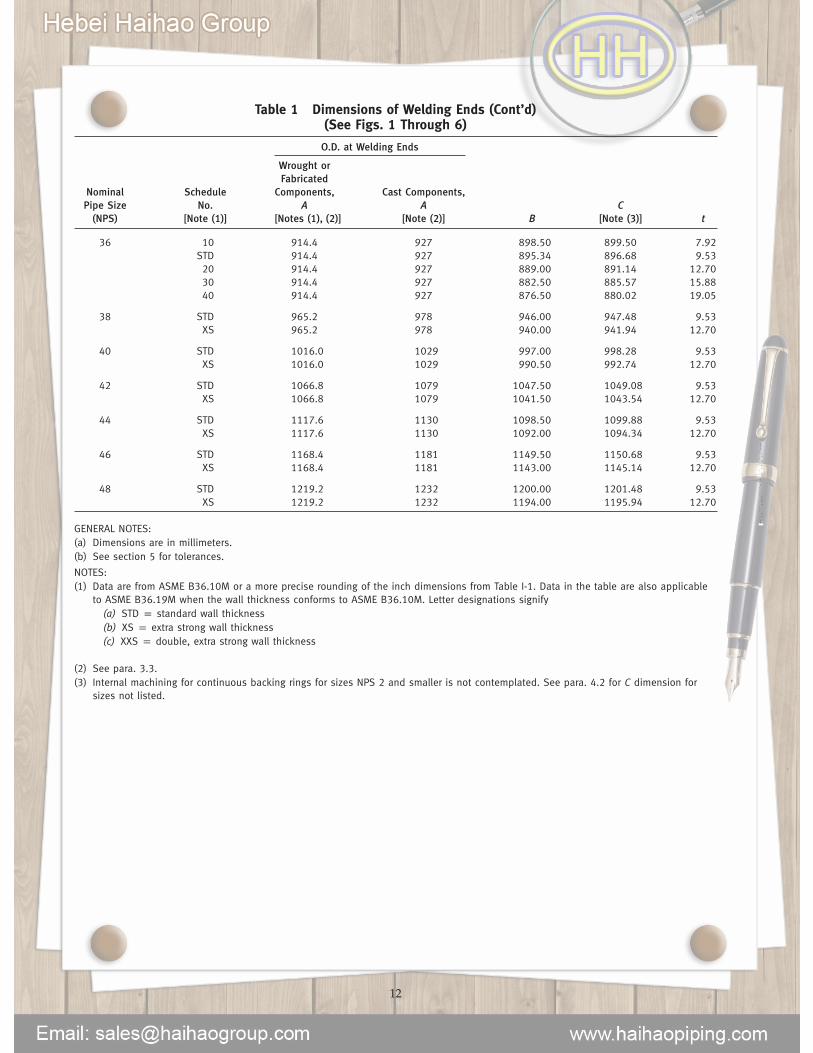
Table 1 Dimensions of Welding Ends (Cont’d)(See Figs. 1 Through 6)
O.D. at Welding Ends
Wrought orFabricated
Nominal Schedule Components, Cast Components,Pipe Size No. A A C
(NPS) [Note (1)] [Notes (1), (2)] [Note (2)] B [Note (3)] t
36 10 914.4 927 898.50 899.50 7.92STD 914.4 927 895.34 896.68 9.5320 914.4 927 889.00 891.14 12.7030 914.4 927 882.50 885.57 15.8840 914.4 927 876.50 880.02 19.05
38 STD 965.2 978 946.00 947.48 9.53XS 965.2 978 940.00 941.94 12.70
40 STD 1016.0 1029 997.00 998.28 9.53XS 1016.0 1029 990.50 992.74 12.70
42 STD 1066.8 1079 1047.50 1049.08 9.53XS 1066.8 1079 1041.50 1043.54 12.70
44 STD 1117.6 1130 1098.50 1099.88 9.53XS 1117.6 1130 1092.00 1094.34 12.70
46 STD 1168.4 1181 1149.50 1150.68 9.53XS 1168.4 1181 1143.00 1145.14 12.70
48 STD 1219.2 1232 1200.00 1201.48 9.53XS 1219.2 1232 1194.00 1195.94 12.70
GENERAL NOTES:(a) Dimensions are in millimeters.(b) See section 5 for tolerances.
NOTES:(1) Data are from ASME B36.10M or a more precise rounding of the inch dimensions from Table I-1. Data in the table are also applicable
to ASME B36.19M when the wall thickness conforms to ASME B36.10M. Letter designations signify(a) STD p standard wall thickness(b) XS p extra strong wall thickness(c) XXS p double, extra strong wall thickness
(2) See para. 3.3.(3) Internal machining for continuous backing rings for sizes NPS 2 and smaller is not contemplated. See para. 4.2 for C dimension for
sizes not listed.
12
--`,,```,,,,````-`-`,,`,,`,`,,`---

MANDATORY APPENDIX IINCH TABLE
This Mandatory Appendix provides a table (Table I-1)of the standard inch dimensions for fittings.
13
--`,,```,,,,````-`-`,,`,,`,`,,`---

(12) Table I-1 Dimensions of Welding Ends(See Figs. 1 Through 6)
O.D. at Welding Ends
Wrought orFabricated
Nominal Schedule Components, Cast Components,Pipe Size No. A A C
(NPS) [Note (1)] [Notes (1), (2)] [Note (2)] B [Note (3)] t
21⁄2 30 2.875 2.96 2.499 2.505 0.18840 2.875 2.96 2.469 2.479 0.20380 2.875 2.96 2.323 2.351 0.276160 2.875 2.96 2.125 2.178 0.375XXS 2.875 2.96 1.771 1.868 0.552
3 30 3.500 3.59 3.124 3.130 0.18840 3.500 3.59 3.068 3.081 0.21680 3.500 3.59 2.900 2.934 0.300160 3.500 3.59 2.624 2.692 0.438XXS 3.500 3.59 2.300 2.409 0.600
31⁄2 30 4.000 4.12 3.624 3.630 0.18840 4.000 4.12 3.548 3.564 0.22680 4.000 4.12 3.364 3.402 0.318
4 30 4.500 4.62 4.124 4.130 0.18840 4.500 4.62 4.026 4.044 0.23780 4.500 4.62 3.826 3.869 0.337120 4.500 4.62 3.624 3.692 0.438160 4.500 4.62 3.438 3.530 0.531XXS 4.500 4.62 3.152 3.279 0.674
5 40 5.563 5.69 5.047 5.070 0.25880 5.563 5.69 4.813 4.866 0.375120 5.563 5.69 4.563 4.647 0.500160 5.563 5.69 4.313 4.428 0.625XXS 5.563 5.69 4.063 4.209 0.750
6 40 6.625 6.78 6.065 6.094 0.28080 6.625 6.78 5.761 5.828 0.432120 6.625 6.78 5.501 5.600 0.562160 6.625 6.78 5.187 5.326 0.719XXS 6.625 6.78 4.897 5.072 0.864
8 20 8.625 8.78 8.125 8.146 0.25030 8.625 8.78 8.071 8.099 0.27740 8.625 8.78 7.981 8.020 0.32260 8.625 8.78 7.813 7.873 0.40680 8.625 8.78 7.625 7.709 0.500
100 8.625 8.78 7.437 7.544 0.594120 8.625 8.78 7.187 7.326 0.719140 8.625 8.78 7.001 7.163 0.812XXS 8.625 8.78 6.875 7.053 0.875160 8.625 8.78 6.813 6.998 0.906
10 20 10.750 10.94 10.250 10.272 0.25030 10.750 10.94 10.136 10.172 0.30740 10.750 10.94 10.020 10.070 0.36560 10.750 10.94 9.750 9.834 0.50080 10.750 10.94 9.562 9.670 0.594100 10.750 10.94 9.312 9.451 0.719
14
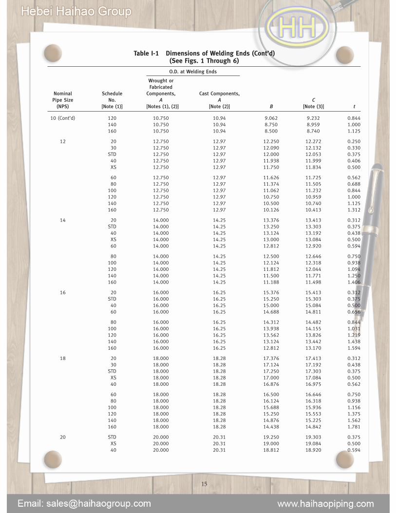
Table I-1 Dimensions of Welding Ends (Cont’d)(See Figs. 1 Through 6)
O.D. at Welding Ends
Wrought orFabricated
Nominal Schedule Components, Cast Components,Pipe Size No. A A C
(NPS) [Note (1)] [Notes (1), (2)] [Note (2)] B [Note (3)] t
10 (Cont’d) 120 10.750 10.94 9.062 9.232 0.844140 10.750 10.94 8.750 8.959 1.000160 10.750 10.94 8.500 8.740 1.125
12 20 12.750 12.97 12.250 12.272 0.25030 12.750 12.97 12.090 12.132 0.330STD 12.750 12.97 12.000 12.053 0.37540 12.750 12.97 11.938 11.999 0.406XS 12.750 12.97 11.750 11.834 0.500
60 12.750 12.97 11.626 11.725 0.56280 12.750 12.97 11.374 11.505 0.688100 12.750 12.97 11.062 11.232 0.844120 12.750 12.97 10.750 10.959 1.000140 12.750 12.97 10.500 10.740 1.125160 12.750 12.97 10.126 10.413 1.312
14 20 14.000 14.25 13.376 13.413 0.312STD 14.000 14.25 13.250 13.303 0.37540 14.000 14.25 13.124 13.192 0.438XS 14.000 14.25 13.000 13.084 0.50060 14.000 14.25 12.812 12.920 0.594
80 14.000 14.25 12.500 12.646 0.750100 14.000 14.25 12.124 12.318 0.938120 14.000 14.25 11.812 12.044 1.094140 14.000 14.25 11.500 11.771 1.250160 14.000 14.25 11.188 11.498 1.406
16 20 16.000 16.25 15.376 15.413 0.312STD 16.000 16.25 15.250 15.303 0.37540 16.000 16.25 15.000 15.084 0.50060 16.000 16.25 14.688 14.811 0.656
80 16.000 16.25 14.312 14.482 0.844100 16.000 16.25 13.938 14.155 1.031120 16.000 16.25 13.562 13.826 1.219140 16.000 16.25 13.124 13.442 1.438160 16.000 16.25 12.812 13.170 1.594
18 20 18.000 18.28 17.376 17.413 0.31230 18.000 18.28 17.124 17.192 0.438STD 18.000 18.28 17.250 17.303 0.375XS 18.000 18.28 17.000 17.084 0.50040 18.000 18.28 16.876 16.975 0.562
60 18.000 18.28 16.500 16.646 0.75080 18.000 18.28 16.124 16.318 0.938100 18.000 18.28 15.688 15.936 1.156120 18.000 18.28 15.250 15.553 1.375140 18.000 18.28 14.876 15.225 1.562160 18.000 18.28 14.438 14.842 1.781
20 STD 20.000 20.31 19.250 19.303 0.375XS 20.000 20.31 19.000 19.084 0.50040 20.000 20.31 18.812 18.920 0.594
15
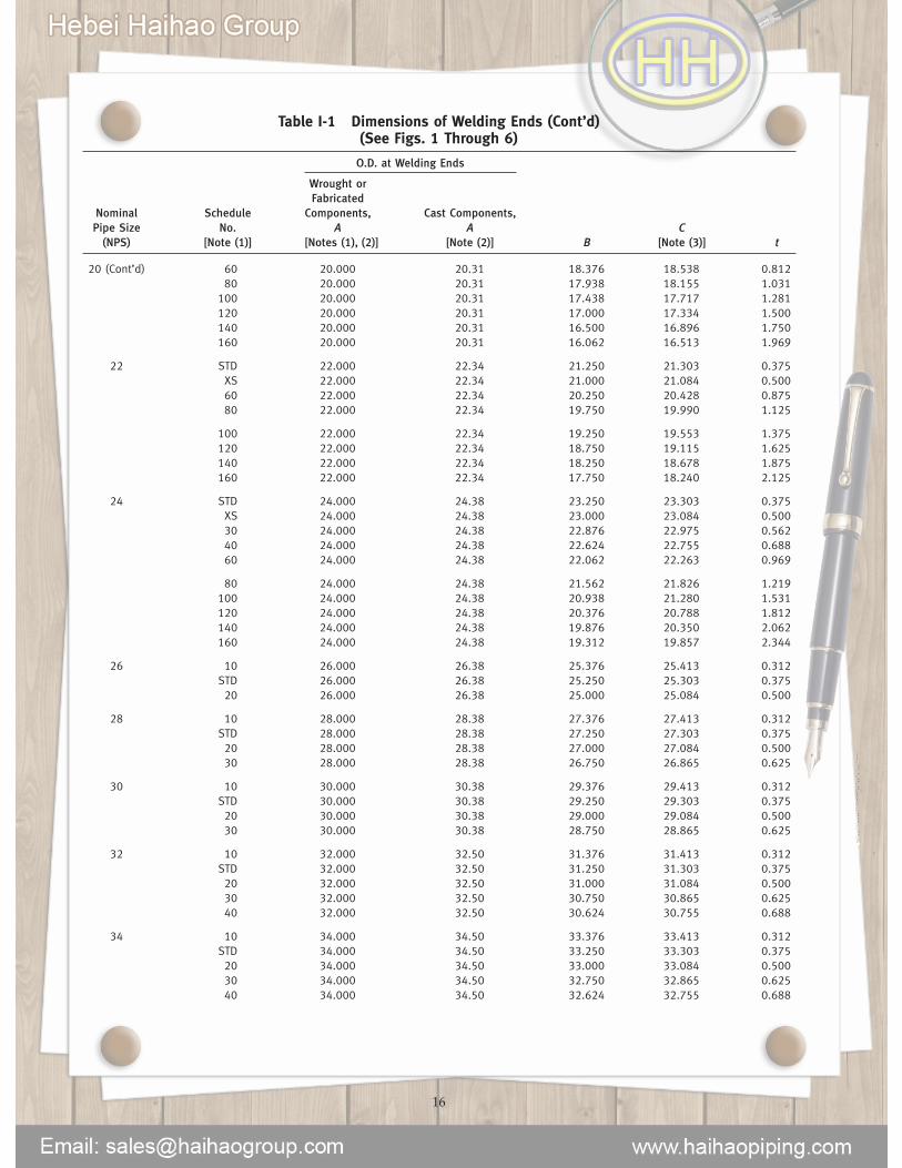
Table I-1 Dimensions of Welding Ends (Cont’d)(See Figs. 1 Through 6)
O.D. at Welding Ends
Wrought orFabricated
Nominal Schedule Components, Cast Components,Pipe Size No. A A C
(NPS) [Note (1)] [Notes (1), (2)] [Note (2)] B [Note (3)] t
20 (Cont’d) 60 20.000 20.31 18.376 18.538 0.81280 20.000 20.31 17.938 18.155 1.031100 20.000 20.31 17.438 17.717 1.281120 20.000 20.31 17.000 17.334 1.500140 20.000 20.31 16.500 16.896 1.750160 20.000 20.31 16.062 16.513 1.969
22 STD 22.000 22.34 21.250 21.303 0.375XS 22.000 22.34 21.000 21.084 0.50060 22.000 22.34 20.250 20.428 0.87580 22.000 22.34 19.750 19.990 1.125
100 22.000 22.34 19.250 19.553 1.375120 22.000 22.34 18.750 19.115 1.625140 22.000 22.34 18.250 18.678 1.875160 22.000 22.34 17.750 18.240 2.125
24 STD 24.000 24.38 23.250 23.303 0.375XS 24.000 24.38 23.000 23.084 0.50030 24.000 24.38 22.876 22.975 0.56240 24.000 24.38 22.624 22.755 0.68860 24.000 24.38 22.062 22.263 0.969
80 24.000 24.38 21.562 21.826 1.219100 24.000 24.38 20.938 21.280 1.531120 24.000 24.38 20.376 20.788 1.812140 24.000 24.38 19.876 20.350 2.062160 24.000 24.38 19.312 19.857 2.344
26 10 26.000 26.38 25.376 25.413 0.312STD 26.000 26.38 25.250 25.303 0.37520 26.000 26.38 25.000 25.084 0.500
28 10 28.000 28.38 27.376 27.413 0.312STD 28.000 28.38 27.250 27.303 0.37520 28.000 28.38 27.000 27.084 0.50030 28.000 28.38 26.750 26.865 0.625
30 10 30.000 30.38 29.376 29.413 0.312STD 30.000 30.38 29.250 29.303 0.37520 30.000 30.38 29.000 29.084 0.50030 30.000 30.38 28.750 28.865 0.625
32 10 32.000 32.50 31.376 31.413 0.312STD 32.000 32.50 31.250 31.303 0.37520 32.000 32.50 31.000 31.084 0.50030 32.000 32.50 30.750 30.865 0.62540 32.000 32.50 30.624 30.755 0.688
34 10 34.000 34.50 33.376 33.413 0.312STD 34.000 34.50 33.250 33.303 0.37520 34.000 34.50 33.000 33.084 0.50030 34.000 34.50 32.750 32.865 0.62540 34.000 34.50 32.624 32.755 0.688
16
--`,,```,,,,````-`-`,,`,,`,`,,`---

Table I-1 Dimensions of Welding Ends (Cont’d)(See Figs. 1 Through 6)
O.D. at Welding Ends
Wrought orFabricated
Nominal Schedule Components, Cast Components,Pipe Size No. A A C
(NPS) [Note (1)] [Notes (1), (2)] [Note (2)] B [Note (3)] t
36 10 36.000 36.50 35.376 35.413 0.312STD 36.000 36.50 35.250 35.303 0.37520 36.000 36.50 35.000 35.084 0.50030 36.000 36.50 34.750 34.865 0.62540 36.000 36.50 34.500 34.646 0.750
38 STD 38.000 38.50 37.250 37.303 0.375XS 38.000 38.50 36.000 37.084 0.500
40 STD 40.000 40.50 39.250 39.303 0.375XS 40.000 40.50 39.000 39.084 0.500
42 STD 42.000 42.50 41.250 41.303 0.375XS 42.000 42.50 41.000 41.084 0.500
44 STD 44.000 44.50 43.250 43.303 0.375XS 44.000 44.50 43.000 43.084 0.500
46 STD 46.000 46.50 45.250 45.303 0.375XS 46.000 46.50 45.000 45.084 0.500
48 STD 48.000 48.50 47.250 47.303 0.375XS 48.000 48.50 47.000 47.084 0.500
GENERAL NOTES:(a) Dimensions are in inches.(b) See section 5 for tolerances.
NOTES:(1) Data are from ASME B36.10M and are also applicable to ASME B36.19M data when the wall thickness conforms to ASME B36.10M.
Letter designations signify(a) STD p standard wall thickness(b) XS p extra strong wall thickness(c) XXS p double, extra strong wall thickness
(2) See para. 3.3.(3) Internal machining for continuous backing rings for sizes NPS 2 and smaller is not contemplated. See para. 4.2 for C dimension for
sizes not listed.
17
--`,,```,,,,````-`-`,,`,,`,`,,`---

(12) MANDATORY APPENDIX IIREFERENCES
The following is a list of publications referenced inthis Standard. Unless otherwise specified, the latest edi-tion of ASME publications shall apply.
ASME B16.5, Pipe Flanges and Flanged FittingsASME B16.9, Factory-Made Wrought ButtweldingFittings
ASME B16.47, Large Diameter Steel FlangesASME B36.10M, Welded and Seamless Wrought SteelPipe
ASME B36.19M, Stainless Steel Pipe
Publisher: The American Society of MechanicalEngineers (ASME), Three ParkAvenue, NewYork, NY10016-5990;OrderDepartment: 22 LawDrive, P.O. Box2900, Fairfield, NJ 07007-2900 (www.asme.org)
ASTM A106/A106M-11, Specification for SeamlessCarbon Steel Pipe for High-Temperature Service
ASTM A335/A335M-11, Specification for SeamlessFerritic Alloy Steel Pipe for High-Temperature Service
18
ASTM E29-08, Standard Practice for Using SignificantDigits in Test Data to Determine Conformance WithSpecifications
Publisher: American Society for Testing and Materials(ASTM International), 100 Barr HarborDrive, P.O. BoxC700, West Conshohocken, PA 19428-2959(www.astm.org)
ISO 9000-2005, Quality management systems —Fundamentals and vocabulary1
ISO 9001-2008, Quality management systems —Requirements1
ISO 9004-2009, Quality management systems —Guidelines for performance improvement1
Publisher: International Organization forStandardization (ISO), Central Secretariat, 1 ch. de laVoie-Creuse, Case postale 56, CH-1211, Geneve 20,Switzerland/Suisse (www.iso.org)
1 May also be obtained from American National StandardsInstitute (ANSI), 25 West 43rd Street, New York, NY 10036.
--`,,```,,,,````-`-`,,`,,`,`,,`---

NONMANDATORY APPENDIX AQUALITY SYSTEM PROGRAM
The products manufactured in accordance with thisStandard shall be produced under a quality system pro-gram following the principles of an appropriate stan-dard from the ISO 9000 series.1 A determination of theneed for registration and/or certification of the product
1 The series is also available from the American NationalStandards Institute (ANSI) and the American Society for Quality(ASQ) as American National Standards that are identified by theprefix “Q,” replacing the prefix “ISO.” Each standard of the seriesis listed under References in Mandatory Appendix II.
19
manufacturer’s quality system program by an indepen-dent organization shall be the responsibility of the man-ufacturer. The detailed documentation demonstratingprogram compliance shall be available to the purchaserat the manufacturer ’s facility. A written summarydescription of the program utilized by the product man-ufacturer shall be available to the purchaser uponrequest. The product manufacturer is defined as theentity whose name or trademark appears on the productin accordancewith themarking or identification require-ments of this Standard.
--`,,```,,,,````-`-`,,`,,`,`,,`---

B16 AMERICAN NATIONAL STANDARDS FOR PIPING,PIPE FLANGES, FITTINGS, AND VALVES
Gray Iron Pipe Flanges and Flanged Fittings (Classes 25, 125, and 250) . . . . . . . . . . . . . . . . . . . . . . . . . . . . . . . . . . . . . . . . . . . . . . . B16.1-2010Malleable Iron Threaded Fittings: Classes 150 and 300. . . . . . . . . . . . . . . . . . . . . . . . . . . . . . . . . . . . . . . . . . . . . . . . . . . . . . . . . . . . . B16.3-2011Gray Iron Threaded Fittings: Classes 125 and 250 . . . . . . . . . . . . . . . . . . . . . . . . . . . . . . . . . . . . . . . . . . . . . . . . . . . . . . . . . . . . . . . . . B16.4-2011Pipe Flanges and Flanged Fittings NPS 1⁄2 Through NPS 24 Metric/Inch Standard . . . . . . . . . . . . . . . . . . . . . . . . . . . . . . . . . . . . . . . . B16.5-2009Factory-Made Wrought Buttwelding Fittings. . . . . . . . . . . . . . . . . . . . . . . . . . . . . . . . . . . . . . . . . . . . . . . . . . . . . . . . . . . . . . . . . . . . . . . B16.9-2007Face-to-Face and End-to-End Dimensions of Valves . . . . . . . . . . . . . . . . . . . . . . . . . . . . . . . . . . . . . . . . . . . . . . . . . . . . . . . . . . . . . . . B16.10-2009Forged Fittings, Socket-Welding and Threaded . . . . . . . . . . . . . . . . . . . . . . . . . . . . . . . . . . . . . . . . . . . . . . . . . . . . . . . . . . . . . . . . . . .B16.11-2011Cast Iron Threaded Drainage Fittings . . . . . . . . . . . . . . . . . . . . . . . . . . . . . . . . . . . . . . . . . . . . . . . . . . . . . . . . . . . . . . . . . . . . . . . . . . . B16.12-2009Ferrous Pipe Plugs, Bushings, and Locknuts with Pipe Threads . . . . . . . . . . . . . . . . . . . . . . . . . . . . . . . . . . . . . . . . . . . . . . . . . . . . .B16.14-2010Cast Copper Alloy Threaded Fittings. . . . . . . . . . . . . . . . . . . . . . . . . . . . . . . . . . . . . . . . . . . . . . . . . . . . . . . . . . . . . . . . . . . . . . . . . . . .B16.15-2011Cast Copper Alloy Solder Joint Pressure Fittings . . . . . . . . . . . . . . . . . . . . . . . . . . . . . . . . . . . . . . . . . . . . . . . . . . . . . . . . . . . . . . . . . .B16.18-2012Metallic Gaskets for Pipe Flanges: Ring-Joint, Spiral-Wound, and Jacketed . . . . . . . . . . . . . . . . . . . . . . . . . . . . . . . . . . . . . . . . . . . . .B16.20-2007Nonmetallic Flat Gaskets for Pipe Flanges . . . . . . . . . . . . . . . . . . . . . . . . . . . . . . . . . . . . . . . . . . . . . . . . . . . . . . . . . . . . . . . . . . . . . . .B16.21-2005Wrought Copper and Copper Alloy Solder-Joint Pressure Fittings. . . . . . . . . . . . . . . . . . . . . . . . . . . . . . . . . . . . . . . . . . . . . . . . . . . . .B16.22-2012Cast Copper Alloy Solder Joint Drainage Fittings: DWV . . . . . . . . . . . . . . . . . . . . . . . . . . . . . . . . . . . . . . . . . . . . . . . . . . . . . . . . . . . . . B16.23-2011Cast Copper Alloy Pipe Flanges and Flanged Fittings: Classes 150, 300, 600, 900, 1500, and 2500 . . . . . . . . . . . . . . . . . . . . . . .B16.24-2011Buttwelding Ends. . . . . . . . . . . . . . . . . . . . . . . . . . . . . . . . . . . . . . . . . . . . . . . . . . . . . . . . . . . . . . . . . . . . . . . . . . . . . . . . . . . . . . . . . . .B16.25-2012Cast Copper Alloy Fittings for Flared Copper Tubes. . . . . . . . . . . . . . . . . . . . . . . . . . . . . . . . . . . . . . . . . . . . . . . . . . . . . . . . . . . . . . . . B16.26-2011Wrought Copper and Wrought Copper Alloy Solder-Joint Drainage Fittings — DWV. . . . . . . . . . . . . . . . . . . . . . . . . . . . . . . . . . . . . . .B16.29-2012Manually Operated Metallic Gas Valves for Use in Gas Piping Systems Up to 125 psi(Sizes NPS 1⁄2 Through NPS 2) . . . . . . . . . . . . . . . . . . . . . . . . . . . . . . . . . . . . . . . . . . . . . . . . . . . . . . . . . . . . . . . . . . . . . . .B16.33-2002 (R2007)
Valves — Flanged, Threaded, and Welding End. . . . . . . . . . . . . . . . . . . . . . . . . . . . . . . . . . . . . . . . . . . . . . . . . . . . . . . . . . . . . . . . . . .B16.34-2004Orifice Flanges . . . . . . . . . . . . . . . . . . . . . . . . . . . . . . . . . . . . . . . . . . . . . . . . . . . . . . . . . . . . . . . . . . . . . . . . . . . . . . . . . . . . . . . . . . . . .B16.36-2009Large Metallic Valves for Gas Distribution: Manually Operated, NPS 21⁄2 (DN 65)to NPS 12 (DN 300), 125 psig (8.6 bar) Maximum. . . . . . . . . . . . . . . . . . . . . . . . . . . . . . . . . . . . . . . . . . . . . . . . . . . . . . . . . . . . . . B16.38-2012
Malleable Iron Threaded Pipe Unions: Classes 150, 250, and 300. . . . . . . . . . . . . . . . . . . . . . . . . . . . . . . . . . . . . . . . . . . . . . . . . . .B16.39-2009Manually Operated Thermoplastic Gas Shutoffs and Valves in Gas Distribution Systems . . . . . . . . . . . . . . . . . . . . . . . . . . . . . . . . .B16.40-2008Ductile Iron Pipe Flanges and Flanged Fittings: Classes 150 and 300 . . . . . . . . . . . . . . . . . . . . . . . . . . . . . . . . . . . . . . . . . . . . . . . .B16.42-2011Manually Operated Metallic Gas Valves for Use in Aboveground Piping Systems Up to 5 psi . . . . . . . . . . . . . . . . . . . . . . . . . . . . .B16.44-2012Cast Iron Fittings for Sovent® Drainage Systems. . . . . . . . . . . . . . . . . . . . . . . . . . . . . . . . . . . . . . . . . . . . . . . . . . . . . . . . . . .B16.45-1998 (R2006)Large Diameter Steel Flanges NPS 26 Through NPS 60 Metric/Inch Standard . . . . . . . . . . . . . . . . . . . . . . . . . . . . . . . . . . . . . . . . . .B16.47-2011Line Blanks . . . . . . . . . . . . . . . . . . . . . . . . . . . . . . . . . . . . . . . . . . . . . . . . . . . . . . . . . . . . . . . . . . . . . . . . . . . . . . . . . . . . . . . . . . . . . . . B16.48-2010Factory-Made Wrought Steel Buttwelding Induction Bends for Transportation and Distribution Systems . . . . . . . . . . . . . . . . . . . . .B16.49-2007Wrought Copper and Copper Alloy Braze-Joint Pressure Fittings . . . . . . . . . . . . . . . . . . . . . . . . . . . . . . . . . . . . . . . . . . . . . .B16.50-2001 (R2008)Copper and Copper Alloy Press-Connect Pressure Fittings . . . . . . . . . . . . . . . . . . . . . . . . . . . . . . . . . . . . . . . . . . . . . . . . . . . . . . . . . . B16.51-2011
The ASME Publications Catalog shows a complete list of all the Standards published by the Society. For a complimentary catalog, or the latestinformation about our publications, call 1-800-THE-ASME (1-800-843-2763).
--`,,```,,,,````-`-`,,`,,`,`,,`---