Embed Size (px)
Citation preview
Butter!y Avionics
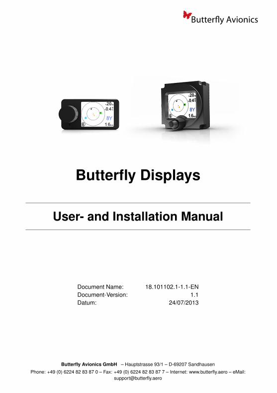
Butterfly Displays
User- and Installation Manual
Document Name: 18.101102.1-1.1-ENDocument-Version: 1.1Datum: 24/07/2013
Butterfly Avionics GmbH – Hauptstrasse 93/1 – D-69207 Sandhausen
Phone: +49 (0) 6224 82 83 87 0 – Fax: +49 (0) 6224 82 83 87 7 – Internet: www.butterfly.aero – eMail:[email protected]
Butter!y Avionics
Notes
i Butterfly Displays User- and Installation Manual • 18.101102.1-1.1-EN
Butter!y Avionics
General Information
IMPORTANT!
Please read this manual carefully before installing or operating the device!
Pay attention to the restrictions on use!
This manual is an essential part of the device and must be kept in a safe place!
Document identification / revision statusThis manual supports the following product types:
• P/N B101 / B102 ”Butterfly Display”
Actual version: Butterfly Displays User- and Installation Manual • 18.101102.1-1.1-EN, Version1.1
Version history
Revision Date Status Author Changes Approved3.2 10/07/2013 Release M. Foerderer Translation fr. german -
Butterfly Displays User- and Installation Manual • 18.101102.1-1.1-EN ii
CONTENTS Butter!y Avionics
Contents1 General 1
1.1 System Description . . . . . . . . . . . . . . . . . . . . . . . . . . . . . . . 1
2 Safety, Liability and Support 22.1 Safety instructions and restrictions on use . . . . . . . . . . . . . . . . . . . . 22.2 Intellectual Property and Liability . . . . . . . . . . . . . . . . . . . . . . . . 22.3 Support . . . . . . . . . . . . . . . . . . . . . . . . . . . . . . . . . . . . . . 2
2.3.1 World . . . . . . . . . . . . . . . . . . . . . . . . . . . . . . . . . . . . . 22.3.2 Europe . . . . . . . . . . . . . . . . . . . . . . . . . . . . . . . . . . . . 2
3 Hardware 33.1 Delivered parts and Accessories . . . . . . . . . . . . . . . . . . . . . . . . . 3
3.1.1 Delivered Parts . . . . . . . . . . . . . . . . . . . . . . . . . . . . . . . . 33.1.2 Accessories . . . . . . . . . . . . . . . . . . . . . . . . . . . . . . . . . . 3
3.2 Hardware-Types . . . . . . . . . . . . . . . . . . . . . . . . . . . . . . . . . 33.2.1 Hardware-Types . . . . . . . . . . . . . . . . . . . . . . . . . . . . . . . 33.2.2 Discontinued hardware-types . . . . . . . . . . . . . . . . . . . . . . . . . 4
3.3 Dimensions . . . . . . . . . . . . . . . . . . . . . . . . . . . . . . . . . . . . 43.3.1 Dimensions 57mm panelmount . . . . . . . . . . . . . . . . . . . . . . . . 43.3.2 Dimensions external unit . . . . . . . . . . . . . . . . . . . . . . . . . . . 5
3.4 Connector and cabling . . . . . . . . . . . . . . . . . . . . . . . . . . . . . . 53.4.1 Power and Data Connector . . . . . . . . . . . . . . . . . . . . . . . . . . 53.4.2 RJ12 cable . . . . . . . . . . . . . . . . . . . . . . . . . . . . . . . . . . 6
3.5 Technical data . . . . . . . . . . . . . . . . . . . . . . . . . . . . . . . . . . 63.5.1 Power supply and consumption . . . . . . . . . . . . . . . . . . . . . . . . 63.5.2 Environmental Conditions . . . . . . . . . . . . . . . . . . . . . . . . . . 6
4 Installation 74.1 Cabling . . . . . . . . . . . . . . . . . . . . . . . . . . . . . . . . . . . . . . 74.2 Mechanical Installation . . . . . . . . . . . . . . . . . . . . . . . . . . . . . . 7
4.2.1 Installation of the 57mm panelmount version . . . . . . . . . . . . . . . . . 74.2.2 Installation of the external version . . . . . . . . . . . . . . . . . . . . . . 84.2.3 Viewing angle and readability . . . . . . . . . . . . . . . . . . . . . . . . . 8
5 Communication and connection to traffic systems 95.1 RS232 interface and compatibility . . . . . . . . . . . . . . . . . . . . . . . . 9
5.1.1 data-rate of RS232 Interface . . . . . . . . . . . . . . . . . . . . . . . . . 95.1.2 Compatible Systems . . . . . . . . . . . . . . . . . . . . . . . . . . . . . 9
5.2 Examples of connections to traffic systems . . . . . . . . . . . . . . . . . . . 95.2.1 Classic FLARM® devices . . . . . . . . . . . . . . . . . . . . . . . . . . . 95.2.2 PowerFLARM® devices . . . . . . . . . . . . . . . . . . . . . . . . . . . . 105.2.3 TRX-devices . . . . . . . . . . . . . . . . . . . . . . . . . . . . . . . . . 10
6 Operation and Controls 11
iii Butterfly Displays User- and Installation Manual • 18.101102.1-1.1-EN
CONTENTS Butter!y Avionics
6.1 Controls . . . . . . . . . . . . . . . . . . . . . . . . . . . . . . . . . . . . . 116.1.1 Controls of different hardware-types and -versions . . . . . . . . . . . . . . 11
6.2 Operation . . . . . . . . . . . . . . . . . . . . . . . . . . . . . . . . . . . . . 116.2.1 Possible user actions for hardware with one single rotary knob . . . . . . . 116.2.2 Possible user actions for hardware with two concentric rotary knobs . . . . 11
6.3 Boot-process and first use . . . . . . . . . . . . . . . . . . . . . . . . . . . . 126.3.1 Switching the unit on / boot process . . . . . . . . . . . . . . . . . . . . . 126.3.2 Settings before first flight . . . . . . . . . . . . . . . . . . . . . . . . . . . 13
7 Traffic Display 147.1 No traffic received . . . . . . . . . . . . . . . . . . . . . . . . . . . . . . . . 147.2 Traffic is received . . . . . . . . . . . . . . . . . . . . . . . . . . . . . . . . . 14
7.2.1 NEAREST and SELECT-mode . . . . . . . . . . . . . . . . . . . . . . . . 157.2.2 Radar-View . . . . . . . . . . . . . . . . . . . . . . . . . . . . . . . . . . 157.2.3 List-view . . . . . . . . . . . . . . . . . . . . . . . . . . . . . . . . . . . 177.2.4 Flarmnet-Funktion . . . . . . . . . . . . . . . . . . . . . . . . . . . . . . 177.2.5 Team-Funktion . . . . . . . . . . . . . . . . . . . . . . . . . . . . . . . . 187.2.6 Stealth-Function . . . . . . . . . . . . . . . . . . . . . . . . . . . . . . . 18
8 Dangerous traffic and warnings 198.0.7 Warning-screen vertical viewing angles . . . . . . . . . . . . . . . . . . . 208.0.8 Warning-screen distance Indicator . . . . . . . . . . . . . . . . . . . . . . 20
8.1 Special warning-screens . . . . . . . . . . . . . . . . . . . . . . . . . . . . . 21
9 Settings 229.0.1 Menu-Diagramme . . . . . . . . . . . . . . . . . . . . . . . . . . . . . . . 22
9.1 Updates . . . . . . . . . . . . . . . . . . . . . . . . . . . . . . . . . . . . . 239.2 Update with PC and Cable . . . . . . . . . . . . . . . . . . . . . . . . . . . . 239.3 Update via PowerFLARM Devices . . . . . . . . . . . . . . . . . . . . . . . . 23
9.3.1 PowerFLARM CORE: . . . . . . . . . . . . . . . . . . . . . . . . . . . . . 239.3.2 PowerFLARM Portable: . . . . . . . . . . . . . . . . . . . . . . . . . . . . 23
1 Butterfly Displays User- and Installation Manual • 18.101102.1-1.1-EN
1 GENERAL Butter!y Avionics
1 General
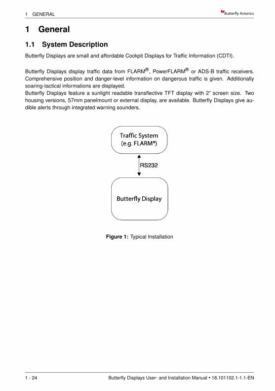
1.1 System DescriptionButterfly Displays are small and affordable Cockpit Displays for Traffic Information (CDTI).
Butterfly Displays display traffic data from FLARM®, PowerFLARM® or ADS-B traffic receivers.Comprehensive position and danger-level information on dangerous traffic is given. Additionallysoaring-tactical informations are displayed.Butterfly Displays feature a sunlight readable transflective TFT display with 2” screen size. Twohousing versions, 57mm panelmount or external display, are available. Butterfly Displays give au-dible alerts through integrated warning sounders.
Figure 1: Typical Installation
1 - 24 Butterfly Displays User- and Installation Manual • 18.101102.1-1.1-EN
Butter!y Avionics 2 SAFETY, LIABILITY AND SUPPORT
2 Safety, Liability and Support
2.1 Safety instructions and restrictions on useInstallation and operation must be on the basis of non-interference with and no hazard to the exist-ing suite of other equipment necessary for safe flying operation, or installed to comply with officialrequirements. Installation and operation must comply with official regulations and requirements.
The pilot is ultimately responsible for all flight decisions and for operating the aircraftsafely at all times. For situational awareness only! Restrictions of connected CollisionWarning Units (CWU) apply.
Never make safety critical decisions based on displayed information.
Butterfly Displays do not have an ETSO or FAA-TSO airworthiness certification. Makesure that it is legal to install it in your aircraft.
Do not use Butterfly Displays if pilot-workload is increased by failure of Butterfly Dis-plays or attached subsystems.
2.2 Intellectual Property and LiabilityButterfly Avionics GmbH, will not be liable for errors/changes/omissions in this document - specifi-cations are subject to change without notice. Butterfly Avionics its associates, development team,suppliers, manufacturers and data suppliers accept no responsibility for any damage or claims thatmay arise from use of Butterfly Vario.
Trademarks referred to in this document are the property of their respective holders. Any decom-piling, disassembly, reverse engineering, or modification of the instrument or firmware are strictlyprohibited without specific written permission from Butterfly Avionics GmbH.
2.3 Support
2.3.1 WorldTo get support, please contact your local authorized Butterfly dealer.
2.3.2 EuropePlease contact us via eMail or Phone. Find more information on www.butterfly.aero or +49 (0) 622482 83 87 0
Butterfly Displays User- and Installation Manual • 18.101102.1-1.1-EN 2 - 24
3 HARDWARE Butter!y Avionics
3 Hardware
3.1 Delivered parts and Accessories
3.1.1 Delivered PartsThe following parts are contained in every Butterfly Display delivery.
Item Part Num-ber
Description
Butterfly Display B101 orB102
Butterfly Display main unit
RJ12 cable - cable RJ12, FLARM-standardInstallation material - 4 screws for mounting the deviceShort Documenta-tion
- Printed short manual
3.1.2 AccessoriesFollowing accessories can be obtained from Butterfly or authorized dealers.
Item Part Num-ber
Description
RAM-Mount for But-terfly Display exter-nal version
6.1.2.0002 Robust RAM-Mount system
Reduction80mm/57mm
27.1.0.0001 Reduction from 80mm to 57mmpanel cutout
Updatecable 1.1.0.0008 Cable for software updates
Visit www.air-store.eu to order accessories.
3.2 Hardware-Types
3.2.1 Hardware-TypesTwo types of Butterfly Displays with identical functionality are available. A 57mm panelmount typeand an external type. The following table shows all currently available hardware types.
Hardware Type Partnumber/Version
Sold from rotary-knobs Housing
57mm Panelmount B102 / 2 Marz 2010 2, concentric Aluminium, powder-coated
57mm Panelmount B102 / 2.1 August 2012 1 Aluminium, powder-coated
externals unit B101 / 3 April 2011 1 Aluminium, powder-coated
3 - 24 Butterfly Displays User- and Installation Manual • 18.101102.1-1.1-EN

Butter!y Avionics 3 HARDWARE
Figure 2: Hardware Versionen: B102 Version 2 / B102 Version 2.1 / B101 Version 3
3.2.2 Discontinued hardware-typesThe following table shows old, no longer sold hardware types/versions.
Hardware Typ Teilenummer/Version
Verkauft ab rotary-knobs Gehause
57mm Panelmount B102 / 1 November 2007 2, concentric plastic57mm Panelmount B102 / 1.1 June 2008 2, concentric plasticexternals unit B101 / 1 November 2007 2, concentric plasticexternals unit B101 / 2 June 2008 2, concentric plastic
3.3 Dimensions
3.3.1 Dimensions 57mm panelmount
Figure 3: Mechanical Dimensions 57mm panelmount
Butterfly Displays User- and Installation Manual • 18.101102.1-1.1-EN 4 - 24
3 HARDWARE Butter!y Avionics
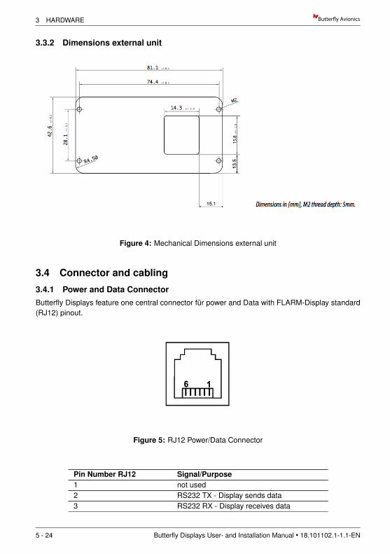
3.3.2 Dimensions external unit
Figure 4: Mechanical Dimensions external unit
3.4 Connector and cabling
3.4.1 Power and Data ConnectorButterfly Displays feature one central connector fur power and Data with FLARM-Display standard(RJ12) pinout.
Figure 5: RJ12 Power/Data Connector
Pin Number RJ12 Signal/Purpose1 not used2 RS232 TX - Display sends data3 RS232 RX - Display receives data
5 - 24 Butterfly Displays User- and Installation Manual • 18.101102.1-1.1-EN
Butter!y Avionics 3 HARDWARE
4 GND - Groand (minus)5 3.0V to 3.3V (Power supply)6 not used
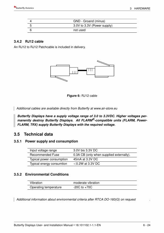
3.4.2 RJ12 cableAn RJ12 to RJ12 Patchcable is included in delivery.
Figure 6: RJ12 cable
Additional cables are available directly from Butterfly at www.air-store.eu
Butterfly Displays have a supply voltage range of 3.0 to 3.3VDC. Higher voltages per-manently destroy Butterfly Displays. All FLARM®-compatible units (FLARM, Power-FLARM, TRX) supply Butterfly Displays with the required voltage.
3.5 Technical data
3.5.1 Power supply and consumption
Input voltage range 3.0V bis 3.3V DCRecommended Fuse 0.3A CB (only when supplied externally).Typical power consumption 45mA at 3.3V DCTypical energy consumtion <0.2W at 3.3V DC
3.5.2 Environmental Conditions
Vibration moderate vibrationOperating temperature -20C to +70C
Additional information about environmental criteria after RTCA DO-160(G) on request .
Butterfly Displays User- and Installation Manual • 18.101102.1-1.1-EN 6 - 24
4 INSTALLATION Butter!y Avionics
4 Installation
The electrical installation has to be undertaken according to the guidelines and regulations applica-ble to the specific aircraft type. When uncertain as to how to perform any aspect of the installation,you should consult with an aeronautical engineer or an aircraft maintenance facility.In all cases the installation is to be performed only with expert advice in accordance with this guid-ance.
4.1 Cabling
When installing Butterfly Display cables, make sure to comply with basic rules of ca-bling in aircraft regarding to EMI minimization. Wrong routing may disturb critical sys-tems like e.g. the aircrafts radio system.
Butterfly Displays are directly supplied using the RJ12 connector. Make sure that all requirementsregarding power supply are being met. Using aviation grade certified wires is recommended.
Never flex or crack cables.
Wrong polarity will permanently destroy the device.
It is very important that the cable is fixated closely to the display so that no force orvibration can be applied to the display connector. The cable may only be shortened byexperts.
4.2 Mechanical Installation
Make sure that the mechanical Installation does not interfere with control movement oremergency procedures . Especially canopy jettison/release must not be constrained.
Butterfly Displays can be installed in the area of the instrument panel of the aircraft. Plan sufficientspace for connecting/disconnecting the main power/data cable. Butterfly Displays have to be in-stalled at least in a distance of 30cm to magnetical compasses.
The enclosure is not watertight. The ingress of solid particles or liquids is to be strictly avoided. Ifthe unit gets moist, dry it before further use. If the unit gets wet, please consult an expert / repairfacility to adequately clean the unit before further use.
Butterfly Displays do not contain a security glass front. Mechanical force applied to thedisplay will destroy the display.
4.2.1 Installation of the 57mm panelmount version
The device is installed in standard-57mm-panel cutout (2.25”) and fixated with four M3 DIN7985screws (included in delivery).
7 - 24 Butterfly Displays User- and Installation Manual • 18.101102.1-1.1-EN
Butter!y Avionics 4 INSTALLATION
After installation of the main unit, the supplied rotary knobs have to be checked/installed and thepower/data cable is connected.
4.2.2 Installation of the external versionThe external display may either be fixated with the supplied M2 screws, with DualLock® tape (notincluded in delivery) or with mounts (see accessories list). Screen direction and thus installationdirection can be modified in 90deg steps.
After installation of the main unit, the power/data cable is connected.
4.2.3 Viewing angle and readabilityWhen installing your display make sure that the viewing angle is as straight as possible. Readabilitylargely depends on the viewing angle.
Polaroid sunglasses may reduce display luminance depending on polarization and screendirection.
Butterfly Display external: The display screen direction can be rotated 90deg-wise for optimalinstallation. Not only ”landscape” but also ”portait-mode” is possible.
Butterfly Displays User- and Installation Manual • 18.101102.1-1.1-EN 8 - 24
5 COMMUNICATION AND CONNECTION TO TRAFFIC SYSTEMS Butter!y Avionics
5 Communication and connection to traffic systems
5.1 RS232 interface and compatibilityButterfly Displays are compatible to systems, that transmit data via TIA-232-F (”RS232”) standardsusing the FLARM-NMEA-Protocol. Butterfly Displays may communicate bidirectionally.
5.1.1 data-rate of RS232 InterfaceThe data-rate of the RS232-interface is variable. Butterfly Displays automatically adjust to the useddata-rate. The minimum data-rate is 19200Bd, the maximum data-rate 57600Bd.
5.1.2 Compatible SystemsAll FLARM®-compatible devices are compatible. A not complete list of the most common devicesis shown in the following table.
Manufacturer DeviceFLARM Technology FLARM®, PowerFLARM®
Garrecht Avionik All TRX-Systems, TRX-1500, TRX-1500A,TRX-2000, TRX1090
LxNav, LX Naviga-tion
All LX-FLARM Systems, LX glide computerwith integrated FLARM®-Module
Ediatec ECW-100
5.2 Examples of connections to traffic systems
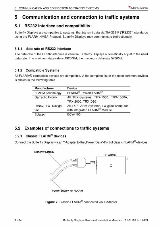
5.2.1 Classic FLARM® devices
Connect the Butterfly Display via an Y-Adapter to the ”Power/Data“-Port of classic FLARM®-devices.
Figure 7: Classic FLARM® connected via Y-Adapter
9 - 24 Butterfly Displays User- and Installation Manual • 18.101102.1-1.1-EN
Butter!y Avionics 5 COMMUNICATION AND CONNECTION TO TRAFFIC SYSTEMS
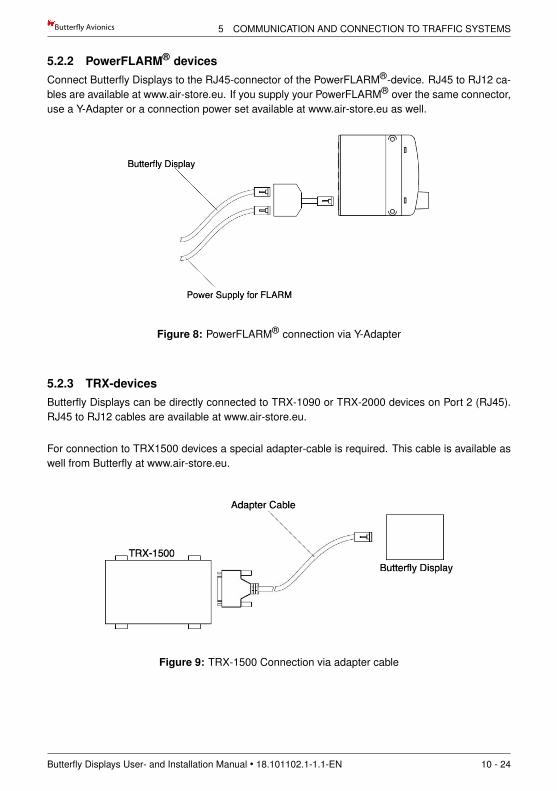
5.2.2 PowerFLARM® devicesConnect Butterfly Displays to the RJ45-connector of the PowerFLARM®-device. RJ45 to RJ12 ca-bles are available at www.air-store.eu. If you supply your PowerFLARM® over the same connector,use a Y-Adapter or a connection power set available at www.air-store.eu as well.
Figure 8: PowerFLARM® connection via Y-Adapter
5.2.3 TRX-devicesButterfly Displays can be directly connected to TRX-1090 or TRX-2000 devices on Port 2 (RJ45).RJ45 to RJ12 cables are available at www.air-store.eu.
For connection to TRX1500 devices a special adapter-cable is required. This cable is available aswell from Butterfly at www.air-store.eu.
Figure 9: TRX-1500 Connection via adapter cable
Butterfly Displays User- and Installation Manual • 18.101102.1-1.1-EN 10 - 24
6 OPERATION AND CONTROLS Butter!y Avionics
6 Operation and Controls
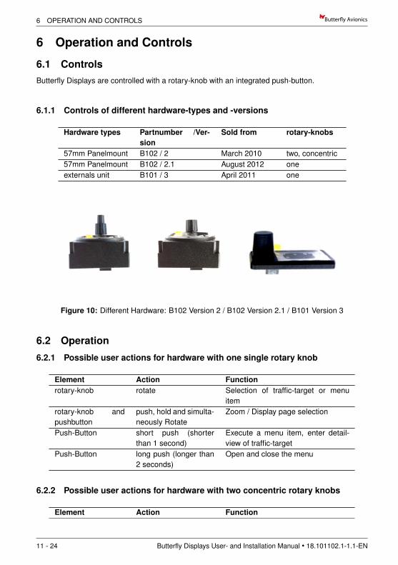
6.1 ControlsButterfly Displays are controlled with a rotary-knob with an integrated push-button.
6.1.1 Controls of different hardware-types and -versions
Hardware types Partnumber /Ver-sion
Sold from rotary-knobs
57mm Panelmount B102 / 2 March 2010 two, concentric57mm Panelmount B102 / 2.1 August 2012 oneexternals unit B101 / 3 April 2011 one
Figure 10: Different Hardware: B102 Version 2 / B102 Version 2.1 / B101 Version 3
6.2 Operation
6.2.1 Possible user actions for hardware with one single rotary knob
Element Action Functionrotary-knob rotate Selection of traffic-target or menu
itemrotary-knob andpushbutton
push, hold and simulta-neously Rotate
Zoom / Display page selection
Push-Button short push (shorterthan 1 second)
Execute a menu item, enter detail-view of traffic-target
Push-Button long push (longer than2 seconds)
Open and close the menu
6.2.2 Possible user actions for hardware with two concentric rotary knobs
Element Action Function
11 - 24 Butterfly Displays User- and Installation Manual • 18.101102.1-1.1-EN
Butter!y Avionics 6 OPERATION AND CONTROLS
small rotary-knob rotate Selection of traffic-target or menuitem
big rotary-knob rotate Zoom / Display page selectionPush-Button short push (shorter
than 1 second)Execute a menu item, enter detail-view of traffic-target
Push-Button long push (longer than2 seconds)
Open and close the menu
6.3 Boot-process and first use
6.3.1 Switching the unit on / boot process
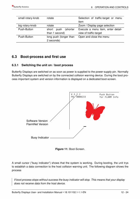
Butterfly Displays are switched on as soon as power is supplied to the power-supply pin. NormallyButterfly Displays are switched on by the connected collision warning device. During the boot pro-cess important system and version information is displayed on a dedicated boot-screen.
+1232m
2.3km6km8Y
+21
+1.2 +433m0.6km
+1.2ms
ms
8Y+1232m2.3km
+1.2ms
342
BD3
+2532m5.5km
+1.2ms
+1232m
2.3km6km8Y
+21
+21
+1.2ms
+1232m
2.3km ….6km8Y
+21
+1.2ms
+1232m
2.3km0.5km8Y
+1.2ms
+433m0.6km
+1.2ms
8Y+1232m2.3km
+1.2ms
342
BD3
+2532m5.5km
+1.2ms
+1232m
2.3km6km8Y
+21
+1.2ms
System
VolumeSystem
FLARM
Volume
Software VersionFlarmNet Version
UTC Time
Busy Indicator
Status Indicators
Distance of selected target
ID of selected target
TargetSelected Target
Circling Target
Transponder Ring (next XPDR equipped aircraft)
Climbrate of selected target
Relative altitude of selected target
V.3.2.2FN: 0000233
Push Button for FLARM Info
12:32:02UTC
GPS TX
Figure 11: Boot-Screen.
A small cursor (”busy indicator”) shows that the system is working. During booting, the unit trysto establish a data connection to the host collision warning unit. The following diagram shows theprocess
If boot process stops without success the busy indicator will stop. This means that your displaydoes not receive data from the host device.
Butterfly Displays User- and Installation Manual • 18.101102.1-1.1-EN 12 - 24
6 OPERATION AND CONTROLS Butter!y Avionics
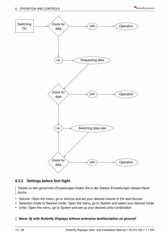
SwitchingOn
check fordata
yes Operation
no Requesting data
check fordata
yes Operation
no Switching data-rate
check fordata
yes Operation
6.3.2 Settings before first flight
Details zu den genannten Einstellungen finden Sie in der Sektion Einstellungen dieses Hand-buchs.
• Volume: Open the menu, go to Volume and set your desired volume of the alert-buzzer.• Selection mode or Nearest mode: Open the menu, go to System and select your desired mode• Units: Open the menu, go to System and set up your desired units-combination
Never fly with Butterfly Displays without extensive familiarization on ground!
13 - 24 Butterfly Displays User- and Installation Manual • 18.101102.1-1.1-EN
Butter!y Avionics 7 TRAFFIC DISPLAY
7 Traffic Display
7.1 No traffic received
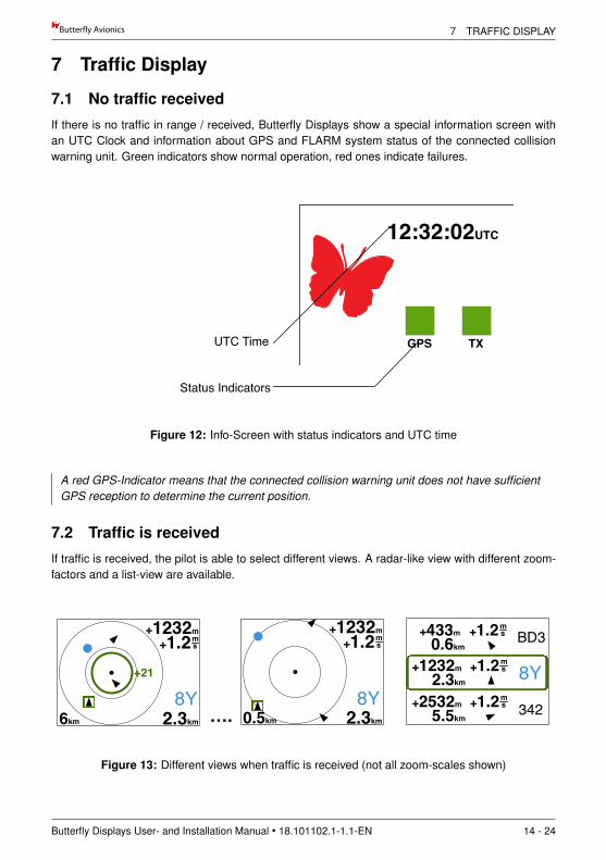
If there is no traffic in range / received, Butterfly Displays show a special information screen withan UTC Clock and information about GPS and FLARM system status of the connected collisionwarning unit. Green indicators show normal operation, red ones indicate failures.
+1232m
2.3km6km8Y
+21
+1.2 +433m0.6km
+1.2ms
ms
8Y+1232m2.3km
+1.2ms
342
BD3
+2532m5.5km
+1.2ms
+1232m
2.3km6km8Y
+21
+21
+1.2ms
+1232m
2.3km ….6km8Y
+21
+1.2ms
+1232m
2.3km0.5km8Y
+1.2ms
+433m0.6km
+1.2ms
8Y+1232m2.3km
+1.2ms
342
BD3
+2532m5.5km
+1.2ms
+1232m
2.3km6km8Y
+21
+1.2ms
System
VolumeSystem
FLARM
Volume
50% Radius (3km)
UTC Time
Busy Indicator
Status Indicators
Distance of selected target
ID of selected target
TargetSelected Target
Circling Target
Transponder Ring (next XPDR equipped aircraft)
Climbrate of selected target
Relative altitude of selected target
V.3.2.2FN: 0000233
Push Button for FLARM Info
12:32:02UTC
GPS TX
Figure 12: Info-Screen with status indicators and UTC time
A red GPS-Indicator means that the connected collision warning unit does not have sufficientGPS reception to determine the current position.
7.2 Traffic is received
If traffic is received, the pilot is able to select different views. A radar-like view with different zoom-factors and a list-view are available.
+1232m
2.3km6km8Y
+21
+1.2 +433m0.6km
+1.2ms
ms
8Y+1232m2.3km
+1.2ms
342
BD3
+2532m5.5km
+1.2ms
+1232m
2.3km6km8Y
+21
+21
+1.2ms
+1232m
2.3km ….6km8Y
+21
+1.2ms
+1232m
2.3km0.5km8Y
+1.2ms
+433m0.6km
+1.2ms
8Y+1232m2.3km
+1.2ms
342
BD3
+2532m5.5km
+1.2ms
+1232m
2.3km6km8Y
+21
+1.2ms
System
FLARM
VolumeSystem
FLARM
Volume
Figure 13: Different views when traffic is received (not all zoom-scales shown)
Butterfly Displays User- and Installation Manual • 18.101102.1-1.1-EN 14 - 24
7 TRAFFIC DISPLAY Butter!y Avionics
7.2.1 NEAREST and SELECT-mode
There are two different modes NEAREST and SELECT-Mode, the current mode can be set up inthe menu, System.
• In SELECT-Mode (Standard) targets can be selected with the rotary knob• on NEAREST-Mode targets can be selected with the rotary knob, the selection automaticallyswitches back to the nearest (closest) target after 10 seconds.
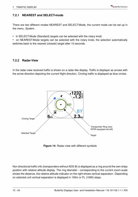
7.2.2 Radar-View
In the radar-view received traffic is shown on a radar-like display. Traffic is displayer as arrows withthe arrow direction depicting the current flight direction. Circling traffic is displayed as blue circles.
+1232m
2.3km6km8Y
+21
+1.2 +433m0.6km
+1.2ms
ms
8Y+1232m2.3km
+1.2ms
342
BD3
+2532m5.5km
+1.2ms
+1232m
2.3km6km8Y
+21
+21
+1.2ms
+1232m
2.3km ….6km8Y
+21
+1.2ms
+1232m
2.3km0.5km8Y
+1.2ms
+433m0.6km
+1.2ms
8Y+1232m2.3km
+1.2ms
342
BD3
+2532m5.5km
+1.2ms
+1232m
2.3km6km8Y
+21
+1.2ms
System
VolumeSystem
FLARM
Volume
50% Radius (3km)
Outer ring radius (6km)Distance of selected target
ID of selected target
TargetSelected Target
Circling Target
Transponder Ring (next XPDR equipped aircraft)
Climbrate of selected target
Relative altitude of selected target
Figure 14: Radar-view with different symbols
Non directional traffic info (transponders without ADS-B) is displayed as a ring around the own shipsposition with relative altitude display. The ring diameter - corresponding to the current zoom-scaleshows the distance, the relative altitude indicator on the right shows vertical separation. Dependingon selected unit vertical separation is displayed in 100m or FL (100ft) steps.
15 - 24 Butterfly Displays User- and Installation Manual • 18.101102.1-1.1-EN
Butter!y Avionics 7 TRAFFIC DISPLAY
+1232m
2.3km6km8Y
+21
+1.2 +433m0.6km
+1.2ms
ms
8Y+1232m2.3km
+1.2ms
342
BD3
+2532m5.5km
+1.2ms
+1232m
2.3km6km8Y
+21
+21
+1.2ms
+1232m
2.3km ….6km8Y
+21
+1.2ms
+1232m
2.3km0.5km8Y
+1.2ms
+433m0.6km
+1.2ms
8Y+1232m2.3km
+1.2ms
342
BD3
+2532m5.5km
+1.2ms
+1232m
2.3km6km8Y
+21
+1.2ms
System
FLARM
VolumeSystem
FLARM
Volume
Figure 15: Transponder-Ring with vertical separation indication in 100ft steps, here 2100mabove
On the right side of the display, additional numerical information to the selected target is shown. If atarget is selected, values like relative altitude, distance, climb/sinkrate and identification regardingthe selected target are shown. When a target is circling, the circling direction is shown as well.Units of displayed values are user-configurable.
+1232m
2.3km6km8Y
+21
+1.2 +433m0.6km
+1.2ms
ms
8Y+1232m2.3km
+1.2ms
342
BD3
+2532m5.5km
+1.2ms
+1232m
2.3km6km8Y
+21
+21
+1.2ms
+1232m
2.3km ….6km8Y
+21
+1.2ms
+1232m
2.3km0.5km8Y
+1.2ms
+433m0.6km
+1.2ms
8Y+1232m2.3km
+1.2ms
342
BD3
+2532m5.5km
+1.2ms
+1232m
2.3km6km8Y
+21
+1.2ms
System
VolumeSystem
FLARM
Volume
50% Radius (3km)
Outer ring radius (6km)Distance of selected target
ID of selected target
TargetSelected Target
Circling Target
Transponder Ring (next XPDR equipped aircraft)
Climbrate of selected target
Relative altitude of selected target
Figure 16: Radar view: values of selected target
+1232m
2.3km6km8Y
+21
+1.2 +433m0.6km
+1.2ms
ms
8Y+1232m2.3km
+1.2ms
342
BD3
+2532m5.5km
+1.2ms
+1232m
2.3km6km8Y
+21
+21
+1.2ms
+1232m
2.3km ….6km8Y
+21
+1.2ms
+1232m
2.3km0.5km8Y
+1.2ms
+433m0.6km
+1.2ms
8Y+1232m2.3km
+1.2ms
342
BD3
+2532m5.5km
+1.2ms
+1232m
2.3km6km8Y
+21
+1.2ms
System
FLARM
VolumeSystem
FLARM
Volume
Figure 17: Circling direction right and left
The current zoom-level of the radar screen (magnification) is shown in the lower left-hand corner.The displayed value corresponds to the outer range-circle of the radar screen. The inner range
Butterfly Displays User- and Installation Manual • 18.101102.1-1.1-EN 16 - 24
7 TRAFFIC DISPLAY Butter!y Avionics
circle is a half of the outer one. If traffic is outside of the currently set up range, it still is shown onthe edge of the radar for better situational awareness at high zoom-scales.
+1232m
2.3km6km8Y
+21
+1.2 +433m0.6km
+1.2ms
ms
8Y+1232m2.3km
+1.2ms
342
BD3
+2532m5.5km
+1.2ms
+1232m
2.3km6km8Y
+21
+21
+1.2ms
+1232m
2.3km ….6km8Y
+21
+1.2ms
+1232m
2.3km0.5km8Y
+1.2ms
+433m0.6km
+1.2ms
8Y+1232m2.3km
+1.2ms
342
BD3
+2532m5.5km
+1.2ms
+433m0.6km
+1.2ms
8Y+1232m2.3km
+1.2ms
342
BD3
+2532m5.5km
+1.2ms
+1232m
2.3km6km8Y
+21
+1.2ms
System
VolumeSystem
FLARM
Volume
Software VersionFlarmNet Version
UTC Time
Selected Target
Busy Indicator
Status Indicators
Distance of selected target
ID of selected target
TargetSelected Target
Circling Target
Transponder Ring (next XPDR equipped aircraft)
Climbrate of selected target
Relative altitude of selected target
V.3.2.2FN: 0000233
Push Button for FLARM Info
12:32:02UTC
GPS TX
Figure 18: High zoom scale, targets with larger distance than zoom-scale still are displayedon the edge of the radar screen.
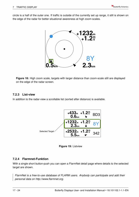
7.2.3 List-viewIn addition to the radar-view a scrollable list (sorted after distance) is available.
+1232m
2.3km6km8Y
+21
+1.2 +433m0.6km
+1.2ms
ms
8Y+1232m2.3km
+1.2ms
342
BD3
+2532m5.5km
+1.2ms
+1232m
2.3km6km8Y
+21
+21
+1.2ms
+1232m
2.3km ….6km8Y
+21
+1.2ms
+1232m
2.3km0.5km8Y
+1.2ms
+433m0.6km
+1.2ms
8Y+1232m2.3km
+1.2ms
342
BD3
+2532m5.5km
+1.2ms
+433m0.6km
+1.2ms
8Y+1232m2.3km
+1.2ms
342
BD3
+2532m5.5km
+1.2ms
+1232m
2.3km6km8Y
+21
+1.2ms
System
VolumeSystem
FLARM
Volume
Software VersionFlarmNet Version
UTC Time
Selected Target
Busy Indicator
Status Indicators
Distance of selected target
ID of selected target
TargetSelected Target
Circling Target
Transponder Ring (next XPDR equipped aircraft)
Climbrate of selected target
Relative altitude of selected target
V.3.2.2FN: 0000233
Push Button for FLARM Info
12:32:02UTC
GPS TX
Figure 19: Listview
7.2.4 Flarmnet-FunktionWith a single short button-push you can open a FlarmNet detail page where details to the selectedtarget are shown.
FlarmNet is a free-to-use database of FLARM users. Anybody can participate and add theirpersonal data on http://www.flarmnet.org.
17 - 24 Butterfly Displays User- and Installation Manual • 18.101102.1-1.1-EN
Butter!y Avionics 7 TRAFFIC DISPLAY
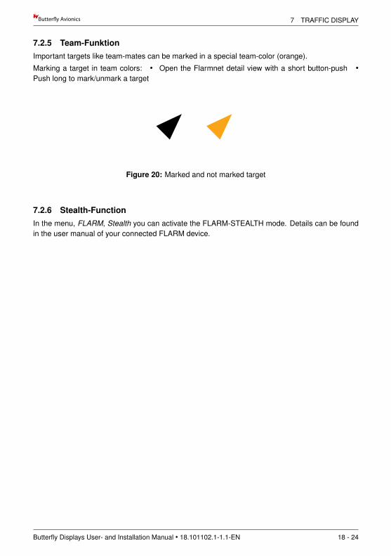
7.2.5 Team-FunktionImportant targets like team-mates can be marked in a special team-color (orange).
Marking a target in team colors: • Open the Flarmnet detail view with a short button-push •Push long to mark/unmark a target
+1232m
2.3km6km8Y
+21
+1.2 +433m0.6km
+1.2ms
ms
8Y+1232m2.3km
+1.2ms
342
BD3
+2532m5.5km
+1.2ms
+1232m
2.3km6km8Y
+21
+21
+1.2ms
+1232m
2.3km ….6km8Y
+21
+1.2ms
+1232m
2.3km0.5km8Y
+1.2ms
+433m0.6km
+1.2ms
8Y+1232m2.3km
+1.2ms
342
BD3
+2532m5.5km
+1.2ms
+1232m
2.3km6km8Y
+21
+1.2ms
System
FLARM
VolumeSystem
FLARM
Volume
Figure 20: Marked and not marked target
7.2.6 Stealth-FunctionIn the menu, FLARM, Stealth you can activate the FLARM-STEALTH mode. Details can be foundin the user manual of your connected FLARM device.
Butterfly Displays User- and Installation Manual • 18.101102.1-1.1-EN 18 - 24
8 DANGEROUS TRAFFIC AND WARNINGS Butter!y Avionics
8 Dangerous traffic and warnings
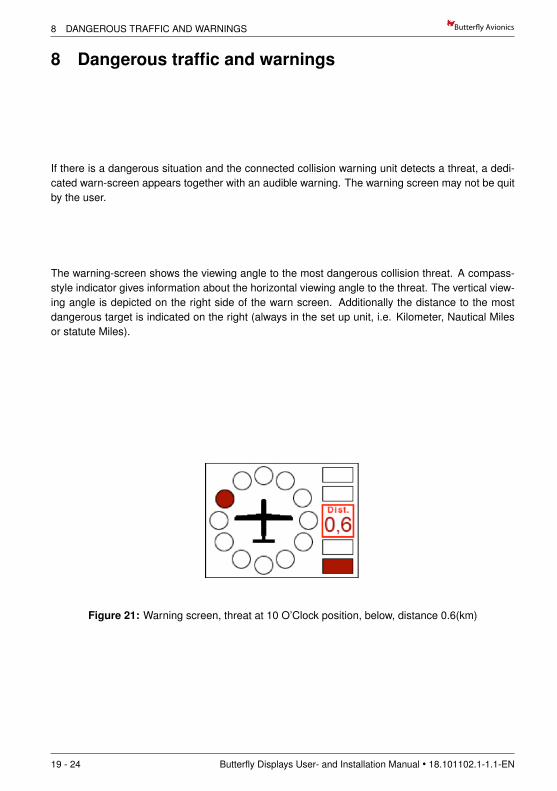
If there is a dangerous situation and the connected collision warning unit detects a threat, a dedi-cated warn-screen appears together with an audible warning. The warning screen may not be quitby the user.
The warning-screen shows the viewing angle to the most dangerous collision threat. A compass-style indicator gives information about the horizontal viewing angle to the threat. The vertical view-ing angle is depicted on the right side of the warn screen. Additionally the distance to the mostdangerous target is indicated on the right (always in the set up unit, i.e. Kilometer, Nautical Milesor statute Miles).
Figure 21: Warning screen, threat at 10 O’Clock position, below, distance 0.6(km)
19 - 24 Butterfly Displays User- and Installation Manual • 18.101102.1-1.1-EN
Butter!y Avionics 8 DANGEROUS TRAFFIC AND WARNINGS
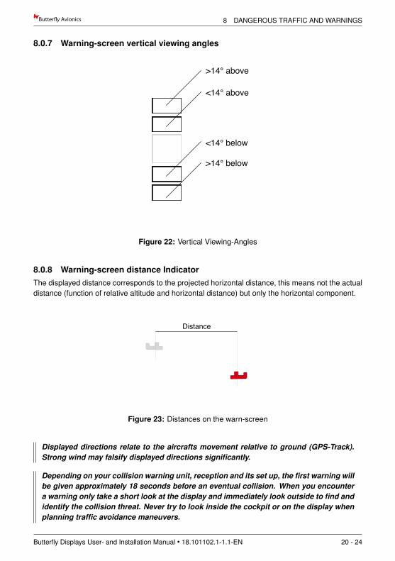
8.0.7 Warning-screen vertical viewing angles
<14° above
>14° above
<14° below
>14° below
Figure 22: Vertical Viewing-Angles
8.0.8 Warning-screen distance IndicatorThe displayed distance corresponds to the projected horizontal distance, this means not the actualdistance (function of relative altitude and horizontal distance) but only the horizontal component.
+1232m
2.3km6km8Y
+21
+1.2 +433m0.6km
+1.2ms
ms
8Y+1232m2.3km
+1.2ms
342
BD3
+2532m5.5km
+1.2ms
+1232m
2.3km6km8Y
+21
+21
+1.2ms
+1232m
2.3km ….6km8Y
+21
+1.2ms
+1232m
2.3km0.5km8Y
+1.2ms
+433m0.6km
+1.2ms
8Y+1232m2.3km
+1.2ms
342
BD3
+2532m5.5km
+1.2ms
+433m0.6km
+1.2ms
8Y+1232m2.3km
+1.2ms
342
BD3
+2532m5.5km
+1.2ms
+1232m
2.3km6km8Y
+21
+1.2ms
System
VolumeSystem
FLARM
Volume
Software VersionFlarmNet Version
UTC Time
Selected Target
Busy Indicator
Status Indicators
Distance of selected target
ID of selected target
TargetSelected Target
Circling Target
Transponder Ring (next XPDR equipped aircraft)
Climbrate of selected target
Relative altitude of selected target
V.3.2.2FN: 0000233
Push Button for FLARM Info
12:32:02UTC
GPS TX
7° above
>14° above
7° below
>14° below
Distance
Figure 23: Distances on the warn-screen
Displayed directions relate to the aircrafts movement relative to ground (GPS-Track).Strong wind may falsify displayed directions significantly.
Depending on your collision warning unit, reception and its set up, the first warning willbe given approximately 18 seconds before an eventual collision. When you encountera warning only take a short look at the display and immediately look outside to find andidentify the collision threat. Never try to look inside the cockpit or on the display whenplanning traffic avoidance maneuvers.
Butterfly Displays User- and Installation Manual • 18.101102.1-1.1-EN 20 - 24
8 DANGEROUS TRAFFIC AND WARNINGS Butter!y Avionics
Carefully read the restrictions of your connected collision warning unit!
Train on ground on how to react in case of a collision warning before flying!
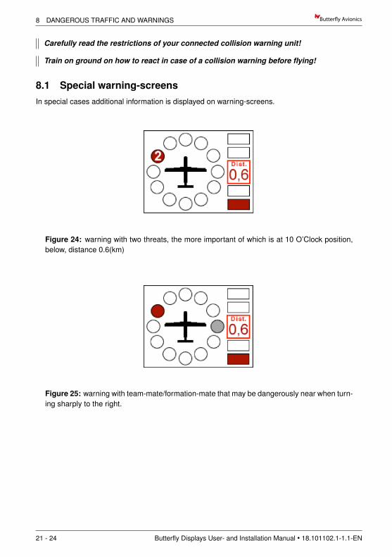
8.1 Special warning-screensIn special cases additional information is displayed on warning-screens.
Figure 24: warning with two threats, the more important of which is at 10 O’Clock position,below, distance 0.6(km)
Figure 25: warning with team-mate/formation-mate that may be dangerously near when turn-ing sharply to the right.
21 - 24 Butterfly Displays User- and Installation Manual • 18.101102.1-1.1-EN
Butter!y Avionics 9 SETTINGS
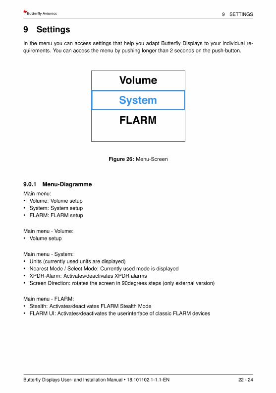
9 SettingsIn the menu you can access settings that help you adapt Butterfly Displays to your individual re-quirements. You can access the menu by pushing longer than 2 seconds on the push-button.
+1232m
2.3km6km8Y
+21
+1.2 +433m0.6km
+1.2ms
ms
8Y+1232m2.3km
+1.2ms
342
BD3
+2532m5.5km
+1.2ms
+1232m
2.3km6km8Y
+21
+21
+1.2ms
+1232m
2.3km ….6km8Y
+21
+1.2ms
+1232m
2.3km0.5km8Y
+1.2ms
+433m0.6km
+1.2ms
8Y+1232m2.3km
+1.2ms
342
BD3
+2532m5.5km
+1.2ms
+1232m
2.3km6km8Y
+21
+1.2ms
System
FLARM
VolumeSystem
FLARM
Volume
Figure 26: Menu-Screen
9.0.1 Menu-DiagrammeMain menu:• Volume: Volume setup• System: System setup• FLARM: FLARM setup
Main menu - Volume:• Volume setup
Main menu - System:• Units (currently used units are displayed)• Nearest Mode / Select Mode: Currently used mode is displayed• XPDR-Alarm: Activates/deactivates XPDR alarms• Screen Direction: rotates the screen in 90degrees steps (only external version)
Main menu - FLARM:• Stealth: Activates/deactivates FLARM Stealth Mode• FLARM UI: Activates/deactivates the userinterface of classic FLARM devices
Butterfly Displays User- and Installation Manual • 18.101102.1-1.1-EN 22 - 24
9 SETTINGS Butter!y Avionics
9.1 Updates
9.2 Update with PC and Cable• Download the update-software and run it on your PC.• Connect the update cable to your pc and supply the cable with power.
Do not connect the Butterfly Display yet.
• Select the appropriate COM-port and process all dialogues with ”OK“.• Push the pushbutton on your display and hold.• Now connect your display and release the pushbutton after connecting.• Wait until the update is finished.
To update your display you need a Butterfly Display update adapter or a similar cable.
9.3 Update via PowerFLARM Devices
9.3.1 PowerFLARM CORE:• Copy Butterfly firmware (.bfw) and/or flarmnet (.bfn) to a USB stick.• Connect stick to Core.• Switch on system with BF display knob pressed.• Verify BF display goes into UPDATE MODE with ’WAITING’, then ’LOADING’.• Wait until BF display restarts (can take up to two minutes).
9.3.2 PowerFLARM Portable:• Copy Butterfly firmware (.bfw) and/or flarmnet (.bfn) to micro SD card.• Insert micro SD card into slot.• Activate menu entry Info -¿ Disp. update.• Switch on system with BF display knob pressed.• Verify BF display goes into UPDATE MODE with ’WAITING’, then ’LOADING’.• Wait until BF display restarts (can take up to two minutes).
23 - 24 Butterfly Displays User- and Installation Manual • 18.101102.1-1.1-EN
Butter!y Avionics 9 SETTINGS
Notes
Butterfly Displays User- and Installation Manual • 18.101102.1-1.1-EN 24 - 24