Embed Size (px)
Citation preview
Progress In Electromagnetics Research Letters, Vol. 69, 45–50, 2017
Butter Fly Shape Compact Microstrip Antenna for Wideband
Applications
Rakesh N. Tiwari1, *, Prabhakar Singh2, and Binod K. Kanaujia3
Abstract—In this article, a novel design of butterfly-shaped compact and small size microstrip antennais proposed. The radiating structure consists of four circular discs in coalesced form and fed with coaxialprobe. The initial antenna resonates at 9.64 GHz with impedance bandwidth of 11.41%. The resonancefrequency is further reduced to 8.12 GHz with bandwidth 10.10%, when a rectangular slot is incorporatedin the initial patch. Finally, two parallel slots are embedded in the initial patch which improves theantenna bandwidth up to 21.50% (6.02–7.47 GHz). The gain and efficiency of this antenna are above8.80 dBi and 90% respectively across the entire operating band. Radiation pattern is calculated atlower end (6.02 GHz), upper end (7.47 GHz) and centre frequency (6.75 GHz) of operating band. Theproposed antenna is fabricated, and measured results are validated with the simulated ones.
1. INTRODUCTION
Modern communication systems are getting smaller and robust day by day. Therefore, the need ofminiaturized, wideband and compact patch antennas are in high demands [1, 2]. Microstrip patchantennas are widely used in this regard as they offer compactness, low profile, light weight and capabilityto easily integrate with circuits. However, the microstrip patch antenna is limited by its narrow operatingbandwidth. Bandwidth improvement and size reduction are major challenges for researchers becausethe bandwidth and size of an antenna are generally mutually conflicting properties. There are variousimpedance matching and feeding techniques used to achieve wide bandwidth [3–5]. Using some narrowslots or removing some portion from the resonators such as patch loaded with U-slot [6, 7], W-slot [8],V-slot [9], T-slot [10] and fractal shaped patch [11, 12] provides a compact antenna with enhancedbandwidth. An asymmetric E-shaped patch and proximity coupled patch antenna [13, 14] also provideimproved bandwidth, but the overall size is compromised. Other methods for broadening the impedancebandwidth include stacked patch antenna and E-shaped patch [15, 16], L-shaped probe and shortingpins [17, 18]. However, these antennas have certain drawbacks in terms of high volumetric size anddesign complexity.
In this paper, a novel and simple butterfly-shaped wideband patch antenna is presented. Such adesign, as per the authors’ knowledge, has not been reported in the literature so far. The proposedantenna structure is coaxially fed and realized using four circular discs of different radii and etchingthe slots in the patch. This structure increases the periphery of the patch which increases the effectivelength of the patch. This increment in the length causes the shift of resonance frequency towardsthe lower side. The antenna parameters such as radiation pattern, bandwidth, gain and efficiencyare calculated by CST microwave studio, and the results are compared with the measured data. Theantenna structure and its fabrications are described in Sections 2 and 3. The measured results anddiscussions are presented in Section 4 followed by conclusion in Section 5.
Received 27 April 2017, Accepted 12 June 2017, Scheduled 5 July 2017* Corresponding author: Rakesh Nath Tiwari ([email protected]).1 Department of Electronics and Communication Engineering, Raffles University, Neemrana, Rajasthan, India. 2 Department ofPhysics, Galgotias University, Greater Noida, Uttar Pradesh, India. 3 School of Computational and Integrative Sciences, JawaharlalNehru University, New Delhi, India.
46 Tiwari, Singh, and Kanaujia
2. ANTENNA STRUCTURE
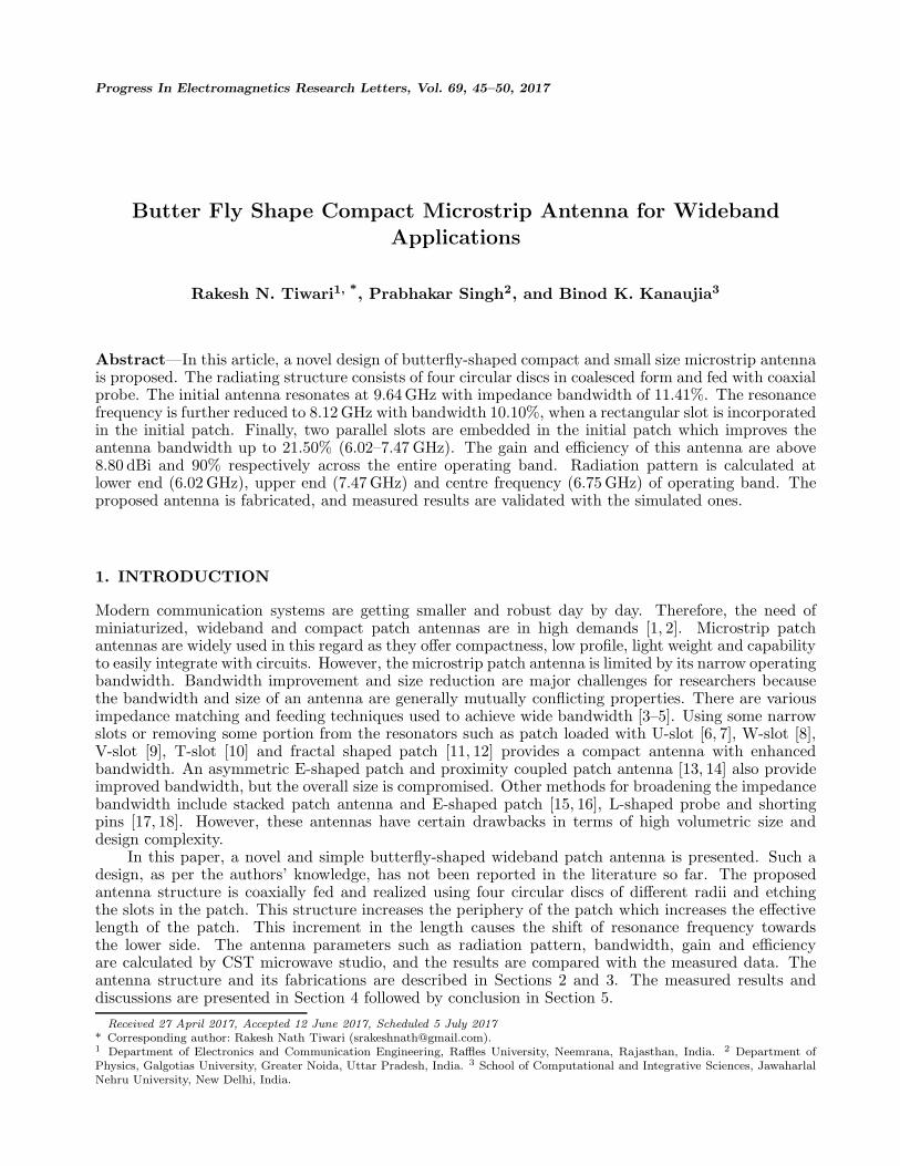
The basic geometry of the proposed antenna is shown in Fig. 1. The proposed antenna is realizedin two steps. (i) Four circular discs of radii r1, r2 and r3 are partially coalesced. The radii of discsalong horizontal direction are taken equal (i.e., r1) while the radii of discs along vertical direction arer2 and r3. (ii) Two parallel slots (dimension L1 × W1) are symmetrically embedded in the patch withrespect to feed point. This perturbation in the patch increases the electrical length of the antenna andhence reduces the resonance frequency. The dimension of vertical and horizontal length (L×W ) of theantenna is 21.0 × 31.8 mm2, and the thickness of the radiating copper patch is 0.1 mm.
(a) (b)
Figure 1. Geometry of the proposed antenna (a) top view and (b) side view.
3. ANTENNA FABRICATION
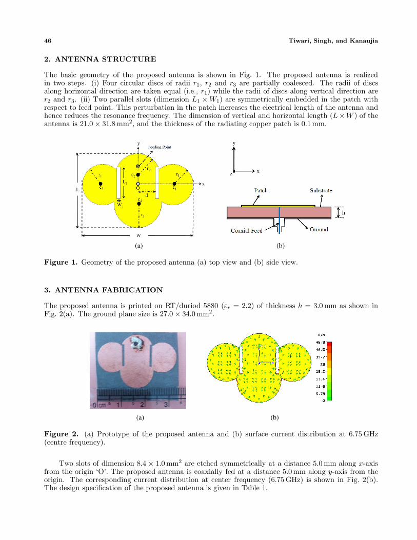
The proposed antenna is printed on RT/duriod 5880 (εr = 2.2) of thickness h = 3.0 mm as shown inFig. 2(a). The ground plane size is 27.0 × 34.0 mm2.
(a) (b)
Figure 2. (a) Prototype of the proposed antenna and (b) surface current distribution at 6.75 GHz(centre frequency).
Two slots of dimension 8.4 × 1.0 mm2 are etched symmetrically at a distance 5.0 mm along x-axisfrom the origin ‘O’. The proposed antenna is coaxially fed at a distance 5.0 mm along y-axis from theorigin. The corresponding current distribution at center frequency (6.75 GHz) is shown in Fig. 2(b).The design specification of the proposed antenna is given in Table 1.
Progress In Electromagnetics Research Letters, Vol. 69, 2017 47
Table 1. Design parameters of the proposed antenna.
Parameters SizeL × W 21 × 31.8 mm2
L1 × W1 8.4 × 1.0 mm2
Substrate RT/duriod 5880 (εr = 2.2)r1 5.8 mmr2 6.5 mmr3 6.8 mmh 3.0 mmd 5.0 mm
4. RESULTS AND DISCUSSION
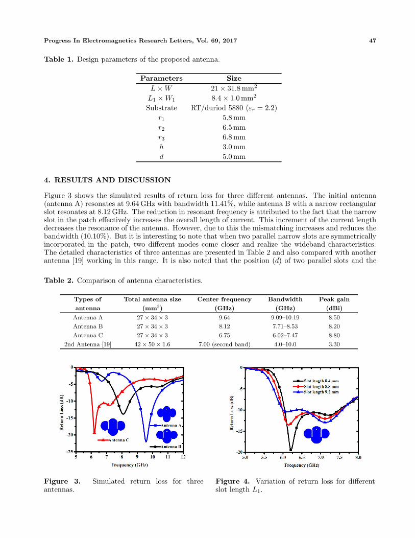
Figure 3 shows the simulated results of return loss for three different antennas. The initial antenna(antenna A) resonates at 9.64 GHz with bandwidth 11.41%, while antenna B with a narrow rectangularslot resonates at 8.12 GHz. The reduction in resonant frequency is attributed to the fact that the narrowslot in the patch effectively increases the overall length of current. This increment of the current lengthdecreases the resonance of the antenna. However, due to this the mismatching increases and reduces thebandwidth (10.10%). But it is interesting to note that when two parallel narrow slots are symmetricallyincorporated in the patch, two different modes come closer and realize the wideband characteristics.The detailed characteristics of three antennas are presented in Table 2 and also compared with anotherantenna [19] working in this range. It is also noted that the position (d) of two parallel slots and the
Table 2. Comparison of antenna characteristics.
Types of
antenna
Total antenna size
(mm3)
Center frequency
(GHz)
Bandwidth
(GHz)
Peak gain
(dBi)
Antenna A 27 × 34 × 3 9.64 9.09–10.19 8.50
Antenna B 27 × 34 × 3 8.12 7.71–8.53 8.20
Antenna C 27 × 34 × 3 6.75 6.02–7.47 8.80
2nd Antenna [19] 42 × 50 × 1.6 7.00 (second band) 4.0–10.0 3.30
Figure 3. Simulated return loss for threeantennas.
Figure 4. Variation of return loss for differentslot length L1.
48 Tiwari, Singh, and Kanaujia
Figure 5. Measured return loss. Figure 6. Variation of radiation efficiency andgain of the proposed antenna.
(a) (c)(b)ϕ = 90
οϕ = 90
οϕ = 90
ο
ϕ = 0ο
ϕ = 0ο
ϕ = 0ο
Figure 7. Radiation pattern of the proposed antenna at (a) f = 6.02 GHz, (b) f = 6.75 GHz, and (c)f = 7.47 GHz.
width of the slot (W1) for antenna C are optimized for the best result. Variation in d or W1 givesunacceptable results, and hence it is not reported in the paper.
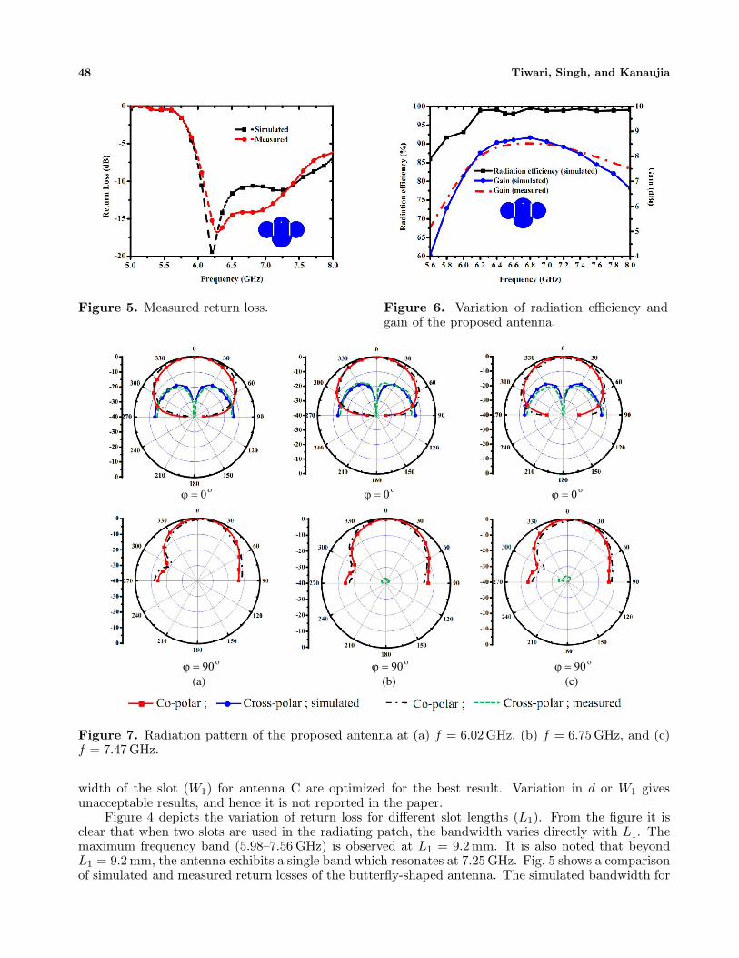
Figure 4 depicts the variation of return loss for different slot lengths (L1). From the figure it isclear that when two slots are used in the radiating patch, the bandwidth varies directly with L1. Themaximum frequency band (5.98–7.56 GHz) is observed at L1 = 9.2 mm. It is also noted that beyondL1 = 9.2 mm, the antenna exhibits a single band which resonates at 7.25 GHz. Fig. 5 shows a comparisonof simulated and measured return losses of the butterfly-shaped antenna. The simulated bandwidth for
Progress In Electromagnetics Research Letters, Vol. 69, 2017 49
given L1 × W1 (8.4 × 1.0 mm2) is compared with measured bandwidth. The calculated bandwidth(20.97%, 6.06–7.48 GHz) is in good agreement with the measured result (19.82%, 6.09–7.43 GHz).
Figure 6 shows the calculated radiation efficiency of the proposed antenna which is found above93% for the entire operating band. Also, the simulated and measured gains are compared in the figure,and they are above 7.22 dBi throughout the band of operation. The maximum realised gain for antennaC is 8.80 dBi. The radiation patterns of the proposed antenna are plotted at the two extreme edges(6.02 GHz and 7.47 GHz) and at center frequency (6.75 GHz) of the usable band (Fig. 7). The calculatedradiation patterns at ϕ = 0◦ and ϕ = 90◦ are plotted and compared with the measured results. Thecross polarisation components are very low at the broad side angle for ϕ = 0◦ and ϕ = 90◦.
The simulated cross polarisation is below −40 dB at the broadside angle. Therefore, it is notobserved at 6.02 GHz, 6.75 GHz and 7.47 GHz for ϕ = 90◦. However, some measured cross polarisationcomponents (except for 6.02 GHz) are observed at ϕ = 90◦ for 6.75 GHz and 7.47 GHz (Figs. 7(b)and (c)). The proposed antenna exhibits a linearly polarized, broadside and almost identical radiationcharacteristic for the entire band of operation.
5. CONCLUSION
In this paper, a novel, compact and small size patch antenna is investigated. The present study infersthat the resonant frequencies and bandwidth are controlled by using thin rectangular slots in thereference antenna. The effective size of the antenna is significantly reduced with maximum bandwidthof 21.50%. The cross polarization of the antenna is very low. The radiation pattern is stable for theentire frequency band, and relative power is maximum at broadside angle. The antenna performancecan be further improved by optimizing the radii of four coalesced disks. The antenna operates in C-bandand can be suitably used for various microwave devices operating in this range, primarily for satellitecommunications.
REFERENCES
1. Shackelford, A. K., K.-F. Lee, and K. M. Luk, “Design of small-size wide-bandwidth microstrip-patch antennas,” IEEE Antennas and Propag. Magazine, Vol. 45, No. 1, 75–83, 2003.
2. Xiong, J., Z. Ying, and S. He, “A broadband low profile patch antenna of compact size with threeresonators,” IEEE Trans. Antennas Propag. Magazine, Vol. 57, No. 6, 1838–1843, 2009.
3. Pandey, G. P., B. K. Kanaujia, A. K. Gautam, and S. K. Gupta, “Ultra-wideband L-strip proximitycoupled slot loaded circular microstrip antenna for modern communication systems,” WirelessPersonal Communication, Vol. 70, No. 1, 139–151, 2013.
4. Deshmukh, A. A. and K. P. Ray, “Broadband proximity-fed square-ring microstrip antennas,”IEEE Antennas Propag. Magazine, Vol. 56, No. 2, 89–107, 2014.
5. Chen, H.-D., “Broadband designs of coplanar capacitively-fed shorted patch antennas,” IETMicrowave Antennas Propagation, Vol. 2, No. 6, 574–579, 2008.
6. Wi, S.-H., Y.-S. Lee, and J.-G. Yook, “Wideband microstrip patch antenna with U-shaped parasiticelements,” IEEE Trans. Antennas Propag., Vol. 55, No. 4, 1196–1199, 2007.
7. Khodaei, G. F., J. Nourinia, and C. Ghobadi, “A practical miniaturized U-slot patch antenna withenhanced bandwidth,” Progress In Electromagnetics Research B, Vol. 3, 47–62, 2008.
8. Neyestanak, A. A. L., F. H. Kashni, and K. Barkeshli, “W-shaped enhanced-bandwidth patchantenna for wireless communications,” Wireless Personal Communication, Vol. 43, No. 4, 1257–1265, 2007.
9. Ansari, J. A., P. Singh, S. K. Dubey, R. U. Khan, and B. R. Vishvakarma, “Analysis of stacked V-slot loaded patch antenna for wideband application,” Microwave Optical Technology Letter, Vol. 51,No. 2, 324–330, 2009.
10. Xie, J.-J., Y.-Z. Yin, S.-L. Pan, and L. Sun, “A novel circular slot antenna with two pairs oft-shaped slots for WLAN/WIMAX applications,” Progress In Electromagnetics Research Letters,Vol. 32, 49–57, 2012.
50 Tiwari, Singh, and Kanaujia
11. Krishna, D. D., M. Gopikrihna, C. K. Aanandan, P. Mohanan, and K. Vasudevan, “Compactwideband koch fractal printed slot antenna,” IET Microwave Antennas Propag., Vol. 3, No. 5,782–789, 2009.
12. Sung, Y. J., “Bandwidth enhancement of a wide slot using fractal-shaped sierpinski,” IEEE Trans.Antennas Propag., Vol. 59, No. 8, 3076–3079, 2011.
13. Malekpoor, H. and S. Jam, “Miniaturised asymmetric E-shaped microstrip patch antenna withfolded-patch feed,” IET Microwave Antennas Propag., Vol. 7, No. 2, 85–91, 2013.
14. Sun, D. and L. You, “A broadband impedance matching method for proximity-coupled microstripantenna,” IEEE Trans. Antennas Propag., Vol. 58, No. 4, 1392–1397, 2010.
15. Matin, M. A., B. S. Sharif, and C. C. Tsimenidis, “Probe fed stacked patch antenna for widebandapplications,” IEEE Trans. Antennas Propag., Vol. 55, No. 8, 2385–2388, 2007.
16. Ang, B. K. and B. K. Chung, “A wideband E-shaped microstrip patch antenna for 5–6 GHz wirelesscommunications,” Progress In Electromagnetics Research, Vol. 75, 397–407, 2007.
17. Islam, M. T., “Design analysis of high gain wideband L-probe fed microstrip patch antenna,”Progress In Electromagnetics Research, Vol. 95, 397–407, 2009.
18. Ansari, J. A., P. Singh, and N. P. Yadav, “Analysis of shorting pin loaded half disk patch antennafor wideband operation,” Progress In Electromagnetic Research C, Vol. 6, 179–192, 2009.
19. Zarrabi, F. B., R. Ahmadian, M. Rahimi, and Z. Mansouri, “Dual band antenna designing withcomposite right/left handed,” Microwave Optical Technology Letter, Vol. 57, No. 4, 774–779, 2015.

![A Compact High-Gain Vivaldi Antenna with Improved ...jpier.org/PIERL/pierl68/19.17031506.pdf · Vivaldi antenna [5] is the conventional way to obtain high gain, but it is complicated](https://img.pdfslide.us/doc/110x75/5e798cac4f394332da21d2e1/a-compact-high-gain-vivaldi-antenna-with-improved-jpierorgpierlpierl6819.jpg)