Embed Size (px)
Citation preview
MULTILINGET-6455
Bus Differential ProtectionApplication of PVD Relays Using
Different Ratio Current Transformers
GE Power Management
CONTENTS
The Problem . . . . . . . . . . . . . . . . . . . . . . . . . . . . . . . . . . . . . . . . . . . . . . . . . . . . . . . . . . . . . . . . . . . .3
General Considerations . . . . . . . . . . . . . . . . . . . . . . . . . . . . . . . . . . . . . . . . . . . . . . . . . . . . . . . . . . .4
Solution No. 1 . . . . . . . . . . . . . . . . . . . . . . . . . . . . . . . . . . . . . . . . . . . . . . . . . . . . . . . . . . . . . . . . . . .5
Solution No. 2 . . . . . . . . . . . . . . . . . . . . . . . . . . . . . . . . . . . . . . . . . . . . . . . . . . . . . . . . . . . . . . . . . . .5
Solution No. 3 . . . . . . . . . . . . . . . . . . . . . . . . . . . . . . . . . . . . . . . . . . . . . . . . . . . . . . . . . . . . . . . . . . .6
Solution No. 4 . . . . . . . . . . . . . . . . . . . . . . . . . . . . . . . . . . . . . . . . . . . . . . . . . . . . . . . . . . . . . . . . . . .6
Solution No. 5 . . . . . . . . . . . . . . . . . . . . . . . . . . . . . . . . . . . . . . . . . . . . . . . . . . . . . . . . . . . . . . . . . . .7
Solution No. 6 . . . . . . . . . . . . . . . . . . . . . . . . . . . . . . . . . . . . . . . . . . . . . . . . . . . . . . . . . . . . . . . . . . .8
Solution No. 7 . . . . . . . . . . . . . . . . . . . . . . . . . . . . . . . . . . . . . . . . . . . . . . . . . . . . . . . . . . . . . . . . . . .9
Solution No. 8 . . . . . . . . . . . . . . . . . . . . . . . . . . . . . . . . . . . . . . . . . . . . . . . . . . . . . . . . . . . . . . . . . .11
Figures 1 through 19 . . . . . . . . . . . . . . . . . . . . . . . . . . . . . . . . . . . . . . . . . . . . . . . . . . . . . . . . . . .12-21

3
In some instances it becomes desirable to usePVD relays with current transformers (CT’s) ofdifferent ratios. For example, an existing bushaving four 600-ampere breakers may beprotected with PVD relays. In such applicationsthe (600/5) CT’s associated with these breakerswould all be used on the 600/5 tap. If a newfeeder were to be added to this existing bus,and if this new feeder would have a 1200ampere rating, the associated breaker wouldnormally have 1200/5 CT’s. This would create anapplication problem for the PVD relays whichnormally require the same CT ratio on allcircuits.
In general, it is best to keep the CT ratios all thesame. In the example given previously, this canbe done by simply ordering the 1200-amperebreaker with 1200/10 CT’s for use in the bus-differential protection scheme. If this is notpossible or desirable for any reason, and if therating of the new breaker is twice that of the oldbreakers, two sets of CT’s on the new breakercan be paralleled to obtain the desired ratio.Sometimes, however, the overall problem isoverlooked for one reason or another and theRelay Application Engineer finds himself havingto cope with two different CT ratios. In suchcases, there are several possible solutions to theproblem. In some instances, one or more ofthese may be applicable, but in others none ofthem may suffice. Thus, each possible solutionshould be investigated before deciding toeliminate it. The following pages discuss severalsolutions. It is suggested that solution No. 8 betried first, because, if it works, it is quite simpleto install and it requires no modification to theexisting installation.
THE PROBLEM
Before getting on to the different possiblesolutions, it might be well to first discuss thebasic problem.
The basis of setting the pick-up on the PVD relayis to ensure that neither the 87H or 87L units willpick up to trip the bus for a nearby externalfault. The settings are based on the (mostsevere) assumption that the CT’s nearest thefault saturate completely, while the rest of theCT’s on all the other breakers saturate not at all.The resulting voltage at the relay is thencalculated and used as a basis for setting the87L and 87H units. These calculations assumethat the CT’s have no secondary leakagereactance. This assumption is only valid if theCT secondaries are wound on a toroidal core andif the windings (on the tap used) are completelydistributed around the cores. Figure 1 illustratesthe difference between a completely distributedand a nondistributed secondary winding.
When CT’s with two different ratios areinvolved, it appears that the simple solutionwould be to use the full winding of the lowerratio CT’s and a matching tap on the higher ratioCT’s. For example, with 600/5 and 1200/5 CT’s,the 600/5 CT’s could be used on their fullwinding, and the 1200/5 CT’s could be used ontheir 600/5 taps. If the 600/5 tap (on the 1200/5CT) is completely distributed, this would workfine except for one point. On internal faults, thehigh burden of the PVD relays would result inhigh CT secondary voltages across the fullwinding of the 1200/5 CT’s. The thyrite units inthe PVD will limit the voltage across the 600/5portions of the windings, but this voltage isamplified by a factor of 2 in the 1200/5 CT. Thishigher voltage may exceed the capability of the
Application of PVD Relays Using Different Ratio CT’s
4
insulation in the circuit. The basic problem is tolimit this voltage to safe values without doingthermal damage to the thyrite units.
Over the years there have been severalapproaches suggested. These are noted on thefollowing pages, along with appropriatecomments. One or more of these schemes maysuffice for a given application, or maybe none ofthem will. In any case, before deciding on aparticular approach, the application should befully checked against the actual existingconditions.
GENERAL CONSIDERATIONS
The PVD11C, PVD21A, and PVD21B relayscontain a thyrite stack that consists of four disksin series. The purpose of this thyrite stack is tolimit, to safe values, the peak voltage that can bedeveloped across the PVD relays and theassociated wiring and CT’s during an internalfault. The magnitude of the peak voltage thatcan be developed depends on the magnitude ofthe internal fault current, and on the excitationcharacteristic of the associated CT’s. Thisinformation is given by the curves of Figures 3and 4. In the process of limiting this voltage, thethyrite stack dissipates energy. Informationconcerning this is given by the curves of Figure 2.
The curves of Figure 2 give the watt-secondsdissipated in each of the four thyrite disks –each half cycle as a function of total (theoreticalRMS) symmetrical secondary fault current andthe ES (voltage at the knee of the excitationcurve on log-log paper) of the CT’s. It should benoted that each thyrite disk is capable ofdissipating 1800 watt-seconds of energy.Assuming a PVD operating time of 3 cycles, anda lock out relay time of 1 cycle, the thyrite willbe subjected to the total secondary fault currentfor 4 cycles – or 8 half-cycles. Thus, themaximum dissipation should not exceed 1800/8or 225 watt-seconds per half cycle.
The abscissa of Figure 2 is given as ES perthyrite disk. It should be noted that ES is thevoltage taken at the knee of the excitation curvefor the CT’s used at the tap used. If CT’s withdifferent excitation characteristics are used, ESis taken for the poorest CT. That is, the lowestES is used. For example, if the standard PVD11C,PVD21A, or PVD21B is used (it has 4 thyritedisks in series) and if the poorest CT has an ESof 260 volts on the tap used, ES/thyrite diskwould be 65 volts. If the maximum symmetricalsecondary internal fault current (assuming no CTsaturation) is 200 amperes, each disk willdissipate about 75 watt-seconds per half cycleor a total of 600 watt-seconds in the 4 cyclesrequired to short down the CT’s by the lock outrelay. This is well within the capability of thethyrite. A completely offset fault current will notresult in any greater dissipation and so this neednot be considered.
The curves of Figures 3 and 4 give the peakvoltage that will be developed across eachthyrite disk as a function of ES and themaximum internal fault current for symmetricaland completely offset currents. To use thesecurves, the ES of the poorest CT is divided bythe number of disks in series (4 in this case). Themaximum symmetrical internal secondary faultcurrent (assuming no CT saturation) is used forboth sets of curves to determine the peakvoltage developed across each thyrite disk. Fourtimes this value gives the total peak voltagethat will appear across studs 5 and 6 of thePVD11C, PVD21A, and PVD21B relays.
For example, consider the same conditions of ES = 260 and maximum symmetrical faultcurrent of 200 amperes, we get 540 volts per diskfrom Figure 3 and 490 volts per disk from Figure4. This indicates that in this case a symmetricalfault current will produce a higher peak than anoffset current. The higher of the two valuesshould be used. This yields a maximum peakvoltage of 4 x 540, or 2,160 volts.
5
It is important to recognize that the PVD relaysare all hi-potted in the factory at 3750 volts RMSbetween the coils and the frame, and betweenthe coils and the contacts. A 2500 volts RMS hi-pot is performed between the contacts and theframe. The peak values of these hipots is 5300and 3500 volts, respectively. We have, however,based our application limits on an assumed hi-pot of 1500 volts RMS (2120 peak) which is thestandard for 250 volt equipment. (Twice ratingplus 1000 volts.)
When applying PVD relays, in addition to whatis outlined in the instruction book, dueconsideration must be given to the insulationcapabilities of the other devices that may beconnected to studs 5 and/or 6 of the PVD relay.This includes terminal blocks, leads and cables,current transformers, and any other devices thatmay be in the CT circuits.
The following list of possible solutions to theproblem of mixed CT ratios is in no particularorder.
SOLUTION NO. 1
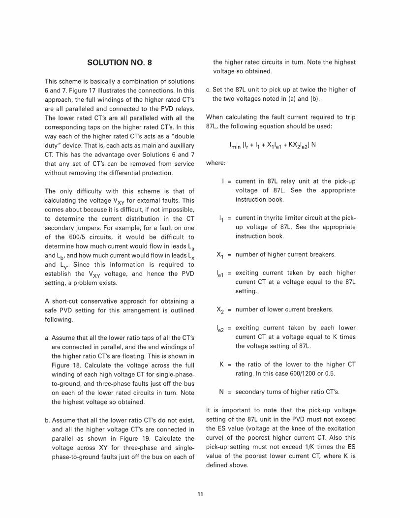
Possibly the simplest solution is to do nothingbut check the higher ratio CT to see if thewinding at the desired tap is completelydistributed. If yes, then check the curves ofFigures 3 and 4 to see if the voltage developedacross the PVD and the open ends of the higherratio CT exceeds safe values. Figure 5 illustratesa typical example.
Use the maximum internal fault current, ES ofthe poorest CT (on the tap used), and the curvesof Figures 3 and 4 to obtain the peak voltageacross studs 5 and 6 of the PVD. Note, for thePVD11C, PVD21A, and PVD21B relays this will be4 times the value read from the ordinate axis.Add to this the peak value of the drops in thelead and CT winding resistance of the higherratio CT. This should be done for each of the
higher CT ratios in turn. This total voltage isthen multiplied by the ratio of total turns toused turns (2 in this case) to obtain the peakvoltage developed.
It is up to the user to determine whether the CTand its associated leads and terminal blocks arecapable of withstanding this magnitude of peakvoltage on an induced voltage test.
The winding to ground voltage that will bedeveloped depends on what part of the CTcircuit is grounded. In Figure 5, the leadassociated with X4 was selected for groundingbecause this will result in a lower voltage toground than if the X2 lead was groundedinstead. It is up to the user to determinewhether or not the CT and its appurtenances arecapable of withstanding the peak voltages toground.
The curves of Figure 2 should also be checked tomake sure that the thyrite will not beoverloaded. This should be checked as outlinedunder “General Considerations” to ensure adissipation of less than 225 watt-seconds perhalf cycle per disk.
In addition to the above considerations, thenormal procedure for setting and checking thesensitivity of the PVD should be pursued asoutlined in the instruction book.
SOLUTION NO. 2
Use the PVD11D, PVD21C, or PVD21D relays; oruse the PVD11C, PVD21A, or PVD21B relays witha second stack of 4 thyrite disks connectedexternally across studs 3 and 6. In either case,this results in two stacks of 4 thyrite disks inparallel. Make external connections as perFigure 5.
Proceed as in Solution No. 1 except enter thecurve of Figures 2, 3, and 4 at a value equal to

6
half the maximum internal fault current. This isso because each thyrite stack will receive onlyhalf the total fault current.
When determining the 87H setting as outlinedin the instruction book the following procedureshould be used:
a) Use the appropriate curve from Figure 7 in thePVD11 book or from Figure 11 in the PVD21book.
b) Use the appropriate curve from Figure 9 in thePVD11 book or from Figure 8 in the PVD21book.
c) When using Figure 10 for the PVD11 relaysread into the curves at a total fault currentthat is one-half of the actual value. Use thecurve that indicates twice the actualresistance and then multiply by 2 the settingfor 87H as read from the abscissa.
SOLUTION NO. 3
Reconnect the thyrite stack in the PVD11C,PVD21A, or PVD21B to remove two disks fromservice. This would leave only two disksconnected between studs 3 and 6 in the relay.Make the external connections as per Figure 5.Check the application as in Solution No. 1. Thefollowing differences in reading the curvesshould be noted.
a) When reading Figure 2, the value for ES perthyrite disk should be based on 2 disks ratherthan 4.
b) When reading Figures 3 and 4, the value forES per thyrite disk should be based on 2 disksrather than 4. The value read for peak voltsshould be multiplied by 2 rather than by 4.
c) When using the curve of Figure 7 in the PVD11instruction book or Figure 11 in the PVD21
book, the curve should be entered at twicethe actual voltage to obtain the current.
d) When using the curve of Figure 9 in thePVD11 instruction book or Figure 8 in thePVD21 book, the curve should be entered attwice the actual voltage to obtain the current.
e) When using the curves of Figure 10 in thePVD11 instruction book, use the curvemarked with twice the actual resistance toobtain the 87H setting.
SOLUTION NO. 4
Reconnect the thyrite stack in the PVD11C,PVD21A, or PVD21B to be a series-parallelarrangement. Two disks in series, in parallelwith the two other disks in series. Make theexternal connections as per Figure 5. Check theapplication as in Solution No. 1. The followingdifferences in reading the curves should beobserved.
a) When reading Figure 2, the value for ES perthyrite disk should be based on two disksrather than four. The curve indicating half theactual amperes should be used.
b) When reading Figures 3 and 4, the value forES per thyrite disk should be based on twodisks rather than four. The curve indicatinghalf the actual amperes should be used. Thevalue read for peak volts should be multipliedby two rather than by four.
c) When using the curve of Figure 7 in the PVD11instruction book or Figure 11 in the PVD21book, enter the curve at twice the actualvoltage and multiply by two the current readfrom the curve.
d) When using the curve of Figure 9 in thePVD11 instruction book or Figure 8 in thePVD21 book, enter the curve at twice the
7
actual voltage and multiply by two thecurrent read from the curve.
e) When using the curves of Figure 10 in thePVD11 book, read into the curves at a totalfault current that is half the actual value. Usethe curve of resistance that is four times theactual resistance and then multiply by 2 thesetting for 87H as read from the abscissa.
SOLUTION NO. 5
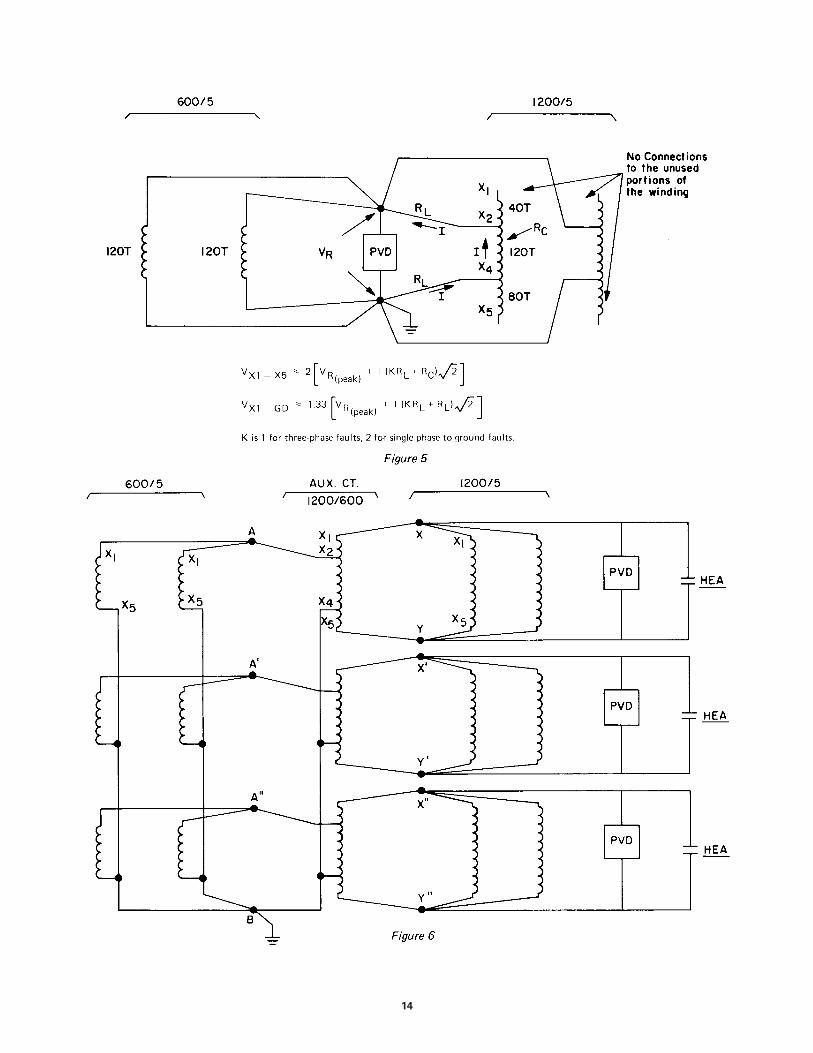
This solution does not require any modificationsto the PVD relays. The approach is to useauxiliary CT’S to match the ratios of thedifferent main CT’s. These auxiliary CT’s musthave completely distributed windings on atoroidal core. For this purpose, three bushingCT’s similar to those in the breakers using thehigher ratio CT’s are recommended.
Figure 6 illustrates the connections that wouldbe employed in a typical application where anumber of 1200/5 CT’s are to be added to anexisting scheme that employs 600/5 CT’s. In thiscase, the auxiliary CT’s would be a set similar tothose in the 1200 ampere breakers. In thissketch it was assumed that originally a junctionexisted (A, A’, A”, and B) for the 600/5 CTterminations in the yard. The 600/5 taps on theauxiliary CT’s are then connected to thisjunction. Another junction is assumed for the1200/5 CT’s (XY, X’Y’, and X”Y”) to which the fullwinding of the auxiliary CT’s are connected aswell as the full winding of all the 1200/5 CT’s andthe PVD relays.
When this scheme is used, it is necessary toestablish the maximum voltage that can appearacross the PVD relays as a result of externalfaults. The PVD relays must then be set for twicethis value. Figure 7 illustrates how thismaximum PVD voltage can be calculated for afault on one of the 600 ampere circuits. It isassumed (in the standard manner) that the CT,
or CT’s, associated with the faulted circuit willsaturate completely. The voltage drops are thensummed back to the auxiliary CT where they arestepped up by a ratio of the total turns to thetap turns (240/120 in this case) and added to thelead drops to the 1200/5 junction (XY). Referringto the equation on Figure 7, the term in therectangular brackets is the internal voltage inthe 120 turns of the auxiliary CT. This ismultiplied by 2 to get the internal voltage acrossthe entire winding. From this internal voltagethe drop in the center portion of the winding issubtracted and the rise in the end sections andthe leads is added to get the net voltage (VXY)on the PVD. This voltage should be calculatedfor faults on each of the 600/5 feeders in turn. Itshould be done for both single-phase-to-groundand three-phase faults. The highest valueobtained for VXY should be recorded.
Figure 8 illustrates how VXY for faults on the1200-ampere feeders can be evaluated. Thisshould be done for both three-phase and single-phase-to-ground faults on each 1200-amperefeeder in turn. The highest value of VXY shouldbe noted.
The higher of the two high values obtained forVXY from Figures 7 and 8 should then bedoubled. This voltage is the minimumpermissible setting for the 87L unit.
It appears likely that, in most cases, the 1200-ampere circuits will be the strongest so thatfaults on the 600-ampere circuits will result inthe highest VXY. This, however, is notnecessarily the case.
When calculating the minimum fault currentrequired to trip 87L the following equationshould be used:
Imin = [Ir + I1 + (X1 + 1)Ie1 + KX2Ie2] N

where:
Ir = current in 87L relay unit at pick-upvoltage of 87L. See the appropriateinstruction book.
I1 = current in thyrite limiter circuit at pick-up voltage of 87L. See the appropriateinstruction book.
X1 = number of higher current breakers.
Ie1 = exciting current taken by each highercurrent CT at a voltage equal to the87L setting.
X2 = number of lower current breakers.
Ie2 = exciting current taken by each lowercurrent CT at a voltage equal to Ktimes the voltage setting of 87L.
K = the ratio of the lower to the higher CTrating. In this case 600/1200 or 0.5.
N = secondary turns of higher ratio CT’s.
It is important to note that the pick-up voltagesetting of the 87L unit in the PVD must notexceed the ES value (voltage at the knee of theexcitation curve) of the poorest higher currentCT. Also this pick-up setting must not exceed1/K times the ES value of the poorest lowercurrent CT, where K is defined above.
THE FOLLOWING THREE SOLUTIONS ARE ALLVARIATIONS OF THE SAME BASIC APPROACH,WHICH IS TO USE THE CT’S IN THE HIGHERRATED BREAKERS AS AUXILIARY CT’S ASWELL AS MAIN CT’S. THESE SCHEMES DO NOTREQUIRE ANY MODIFICATION TO THE PVDNOR DO THEY REQUIRE ANY AUXILIARY CT’S.
SOLUTION NO. 6
Figure 9 illustrates the connections that wouldbe employed in a typical application where1200/5 CT’s are to be added to an existingscheme that employs 600/5 CT’s. In this sketch itwas assumed that a junction originally existed(A, A’, A”, and B) for the 600/5 CT terminationsin the yard. The 600/5 taps on one set of the1200/5 CT’s is connected to this same junction.Another junction is assumed for the 1200/5 CT’s(XY, X’Y’, and X”Y”) to which full windings ofthese CT’s are connected as well as the PVDrelays. In this way, the CT’s on one of the 1200ampere breakers do double duty. Aside from anyother consideration, this scheme has thedisadvantage that, if the CT’s which are used forthe matching function are taken out of servicefor any reason, the bus differential scheme mustbe taken out of service.
When this scheme is used, it is necessary toestablish the maximum voltage that can appearacross the PVD relays as a result of externalfaults. The PVD relays must be set for twice thisvalue. Figure 10 illustrates how this maximumPVD voltage for a fault on one of the 600 amperecircuits can be calculated. It is assumed (in thestandard manner) that the CT or CT’s associatedwith the faulted circuit saturates completely.The voltage drops are then summed back to the“dual purpose” CT’s where they are stepped upby the ratio of the total turns to the tap turns(240/120 in this case) and added to the leaddrops to the 1200/5 junction (XY). Referring tothe equation on Figure 10, the term in therectangular brackets is the internal voltage inthe tapped portion of the “double duty” CT. Thisis multiplied by P (P = 2 in this case) to get theinternal voltage across the entire winding. Tothis internal voltage the rises in the end sectionsand leads are added, while the drop in the centersection is subtracted, to get the net voltage(VXY) on the PVD. This voltage should becalculated for faults on each of the 600/5 feeders
8
9
in turn. It should be done for both three-phaseand single-phase-to-ground faults. The highestvalue obtained should be recorded.
Figure 11 illustrates how VXY can be evaluatedfor faults the feeder associated with the “doubleduty” CT’s. This should be done for both single-phase-to-ground and three-phase faults. Thehigher value for VXY thus obtained should berecorded.
Figure 12 illustrates how VXY can be evaluatedfor faults on any of the other higher-ratedcircuits. Here again this should be done forthree-phase and single-phase-to-ground faultson all the higher-rated circuits. The highestvalue obtained for VXY should be recorded.
The highest of the three values of VXY recordedshould then be doubled. This resulting voltageis the minimum permissible setting for the 87Lunit.
When calculating the fault current required totrip 87L, the following equation should be used:
Imin = [Ir + I1 + X1Ie1 + KX2Ie2] N
where:
Ir = current in 87L relay unit at the pick-upvoltage of 87L. See the appropriateinstruction book.
I1 = current in thyrite limiter circuit at thepick-up voltage of 87L. See theappropriate instruction book.
X1 = number of higher current breakers.
Ie1 = exciting current taken by each highercurrent CT at a voltage equal to the87L setting.
X2 = number of lower current breakers.
Ie2 = exciting current taken by each lowercurrent CT at a voltage equal to Ktimes the voltage setting of 87L.
K = the ratio of the lower to the higher CTrating. In this case 600/1200 or 0.5.
N = secondary turns of higher ratio CT’s.
It is important to note that the pick-up voltagesetting of the 87L unit in the PVD must notexceed the ES value (voltage at the knee of theexcitation curve) of the poorest higher currentCT. Also this pick-up setting must not exceed1/K times the ES value of the poorest lowercurrent CT, where K is defined above.
SOLUTION NO. 7
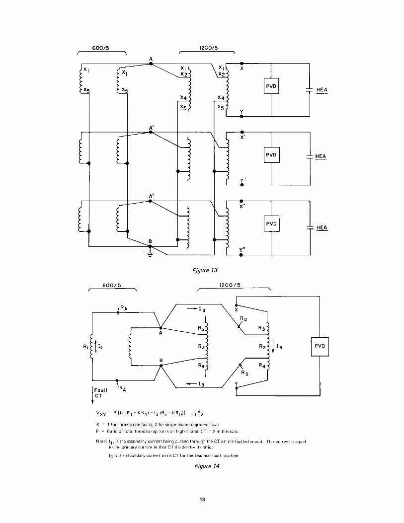
Figure 13 illustrates another arrangement thatcould be employed in a typical applicationwhere 1200/5 CT’s are to be added to an existinginstallation that uses 600/5 CT’s. This schemediffers from that of Solution 6 in that thisscheme parallels the taps on the higher ratedCT’s while in Solution 6 the full windings areparalleled. In Figure 13 it was assumed that ajunction originally existed (A, A’, A”, and B) forthe 600/5 CT terminations in the yard. The 600/5taps on all the 1200/5 CT’s are connected to thissame junction. The PVD relays are thenconnected to the complete winding of only oneset of the 1200/5 CT’s at XY, X’Y’, and X”Y”.Aside from any other consideration, this schemehas the disadvantage that, if the CT’s used forthe matching function are taken out of servicefor any reason, the bus differential scheme mustbe taken out of service.
When this scheme is used, it is necessary toestablish the maximum voltage that can appearacross the PVD relays as a result of externalfaults. The PVD relays must be set for twice thisvalue. Figure 14 illustrates how this maximumPVD voltage for a fault on one of the 600 ampere
circuits can be calculated. It is assumed (in thestandard manner) that the CT or CT’s associatedwith the faulted circuit saturates completely.The voltage drops are then summed back to the“dual purpose” CT’s where they are stepped upby the ratio of the total turns to the tap turns(240/120 in this case). Referring to the equationon Figure 14, the term in the rectangularbrackets is the internal voltage in the tappedportion of the “double duty” CT. This ismultiplied by P (P = 2 in this case) to get theinternal voltage across the entire winding. Fromthis, the internal voltage drop in the centersection is subtracted to get the net voltage(VXY) on the PVD. This voltage should becalculated for faults on each of the 600/5 feedersin turn. It should be done for both three-phaseand single-phase-to-ground faults. The highestvalue obtained should be recorded.
Figure 15 illustrates how VXY can be evaluatedfor faults on the feeder associated with the“double duty” CT’s. This should be done forboth single-phase-to-ground and three-phasefaults. The higher value for VXY thus obtainedshould be recorded.
Figure 12 illustrates how VXY can be evaluatedfor faults on any of the other higher ratedcircuits. Here again this should be done forthree-phase and single-phase-to-ground faultson all the higher-rated circuits. The highestvalue obtained for VXY should be recorded.
The highest of the three values of VXY recordedshould then be doubled. This resulting voltageis the minimum permissible setting for the 87Lunit.
When calculating the fault current required totrip 87L, the following equation should be used:
Imin = [Ir+ I1 + K(X1 - 1)Ie1 + KX2Ie2 + Ie3] N
where:
Ir = current in 87L relay unit at the pick-upvoltage of 87L. See the appropriateinstruction book.
I1 = current in thyrite limiter circuit at thepick-up voltage of 87L. See theappropriate instruction book.
X1 = number of higher current breakers.
Ie1 = exciting current taken by each highercurrent CT at the tap used and at avoltage equal to K times the voltagesetting of 87L.
X2 = number of lower current breakers.
Ie2 = exciting current taken by each lowercurrent CT at a voltage equal to Ktimes the voltage setting of 87L.
Ie3 = exciting current taken by “doubleduty” CT based on the full windingand a voltage equal to the setting of87L.
K = the ratio of the lower to the higher CTrating. In this case 600/1200 or 0.5.
N = secondary turns of higher ratio CT’s.
It is important to note that the pick-up voltagesetting of the 87L unit in the PVD must notexceed the ES value (voltage at the knee of theexcitation curve) of the “double duty” CT. Alsothis pick-up setting must not exceed 1/K timesthe ES value of the poorest lower current CT, normust it exceed 1/K times the ES value of thepoorest higher current CT on the tap used,where K is defined above.
10
11
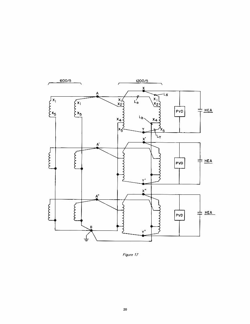
SOLUTION NO. 8
This scheme is basically a combination of solutions6 and 7. Figure 17 illustrates the connections. In thisapproach, the full windings of the higher rated CT’sare all paralleled and connected to the PVD relays.The lower rated CT’s are all paralleled with all thecorresponding taps on the higher rated CT’s. In thisway each of the higher rated CT’s acts as a “doubleduty” device. That is, each acts as main and auxiliaryCT. This has the advantage over Solutions 6 and 7that any set of CT’s can be removed from servicewithout removing the differential protection.
The only difficulty with this scheme is that ofcalculating the voltage VXY for external faults. Thiscomes about because it is difficult, if not impossible,to determine the current distribution in the CTsecondary jumpers. For example, for a fault on oneof the 600/5 circuits, it would be difficult todetermine how much current would flow in leads Laand Lb, and how much current would flow in leads Lxand Ly. Since this information is required toestablish the VXY voltage, and hence the PVDsetting, a problem exists.
A short-cut conservative approach for obtaining asafe PVD setting for this arrangement is outlinedfollowing.
a. Assume that all the lower ratio taps of all the CT’sare connected in parallel, and the end windings ofthe higher ratio CT’s are floating. This is shown inFigure 18. Calculate the voltage across the fullwinding of each high voltage CT for single-phase-to-ground, and three-phase faults just off the buson each of the lower rated circuits in turn. Notethe highest voltage so obtained.
b. Assume that all the lower ratio CT’s do not exist,and all the higher voltage CT’s are connected inparallel as shown in Figure 19. Calculate thevoltage across XY for three-phase and single-phase-to-ground faults just off the bus on each of
the higher rated circuits in turn. Note the highestvoltage so obtained.
c. Set the 87L unit to pick up at twice the higher ofthe two voltages noted in (a) and (b).
When calculating the fault current required to trip87L, the following equation should be used:
Imin [Ir + I1 + X1Ie1 + KX2Ie2] N
where:
I = current in 87L relay unit at the pick-upvoltage of 87L. See the appropriateinstruction book.
I1 = current in thyrite limiter circuit at the pick-up voltage of 87L. See the appropriateinstruction book.
X1 = number of higher current breakers.
Ie1 = exciting current taken by each highercurrent CT at a voltage equal to the 87Lsetting.
X2 = number of lower current breakers.
Ie2 = exciting current taken by each lowercurrent CT at a voltage equal to K timesthe voltage setting of 87L.
K = the ratio of the lower to the higher CTrating. In this case 600/1200 or 0.5.
N = secondary turns of higher ratio CT’s.
It is important to note that the pick-up voltagesetting of the 87L unit in the PVD must not exceedthe ES value (voltage at the knee of the excitationcurve) of the poorest higher current CT. Also thispick-up setting must not exceed 1/K times the ESvalue of the poorest lower current CT, where K isdefined above.

12

13
14

15

16

17
18

19
20

21

�����������������������������������������������������������������������������������������*(�3RZHU�0DQDJHPHQW
215 Anderson AvenueMarkham, OntarioCanada L6E 1B3Tel: (905) 294-6222Fax: (905) 201-2098www.GEindustrial.com/pm