Embed Size (px)
Citation preview

BURETIN Of THE INT[RNUIONAI DAIRY FIOIRUION N0185/1085 ISSN 0250-5118
rriurrr ; wwwq
INTERNATIONAL DAIRY FEDERATION
BULLETIN No 185/1985
ISSN 0250- 5118
() FIL/IDF
Price *: 600 BEF (Belgian Francs) * Including postage - Surface Mail - For orders below 1000 BEF, there is a charge of 300 BEF to cover banking and other charges.
CONTROL SYSTEMS FOR AUTOMATED DAIRY PROCESSES AGUIDE FOR DAIRY PLANT MANAGERS
INDEX
Page
I. INTRODUCTION ........................... 2
II. WHY AND WHAT TO AUTOMATE ? ............. 3
III. CONDITIONS FOR THE EXECUTION OF AN AUTOMATION PROJECT ..................... 7
IV. HOW TO AUTOMATE
A. Definitions of automation level .............. 10
B. Systems available for automation ............. 18
C. Alternative models for operator communication and system architecture ................... 19
D. Item numbering system ................... 21
E. Functional description .................... 23
V. ORGANIZATION AND EXECUTION
Alternative aspects for organizing an automated dairy ............................... 25
Organizing an automation project ............ 28
VI. GLOSSARY OF TERMS ...................... 35
Subscription Price for 1985 Bulletin: 5000 BEF
for all issues and I DF Standards published.
Address Orders to:
International Dairy Federation 41, Square Vergote B - 1040 Brussels (Belgium)
TEL: (02) 733 98 88
TELEX: 63818 IDFFIL

IDF BuHetin 185
I. INTRODUCTION
Automation based on the application of electronic logic for controlling dairy processes began with the introduction of relay-control/ed C/P systems in the 1950's.
Since that time, a/though there have been significant improvements in sensing and operating devices, most of the development has been in the app//cation of improved logic systems to dairying requirements.
A wide choice of systems is now available ranging from simple process plant control pane/s with relays and hard wiring to fully automated systems with on-plant micro-processors using the latest si/icon chip technology instead of relay logic, /inked to a central computer contro//ing, for examp/e, inventory and warehousing as well as plant operations.
The dairyman needs guidance when faced with a choice varying so wide/y in capability and cost. In genera/ he needs to know what benefits can be expected and to be able to judge which opera-tions will be more efficiently performed by applying any given automation system.
When a dairy installs a sophisticated control system, it is important that the dairy is able to hand/e and maintain the system, independent of expensive specialists. This of course requires qua/ified personnel, who in addition to knowledge about dairy technology must also have some training in automatic process control.
Up to now, the universities and dairy schools have had insufficient education in process control, and the dairies have been forced to educate the personnel themselves by special training courses.
A question of current interest is what background knowledge the dairyman ought to have in mathematics and electronics, to study process control and automation, as these subjects are rather theoretical. The main subjects in dairy education are chemistry, microbiology, dairy technology, etc., and the dairyman normally has a rather weak background in pure technical subjects.
However, the aim of this report is not to educate specialists in automation and computer science. The aim is to teach the dairyman sufficient about process control that he is able to discuss with control specialists and have sufficient knowledge to make his decisions.
This document is intended to update and augment the information presented in the following IDF publications:
IDF Document 72 (1973): Automation in the Dairy Industry
IDF Document 100 (1977): Safety and reliability of automated dairy plant.
IDE Bulletin 185
II. WHY AND WHAT TO AUTOMATE? It is probably true to say that virtually any process or system encountered within the dairy industry can be auto-mated to a greater or lesser degree, given the necessary finance. Whether such automation is likely to be of benefit in all cases is another matter and the suitability of any system for automation should always and only be con-sidered along with the benefits expected as a result. Modern dairy planning must take into account the optimum use of energy (in all forms), raw materials (ingre-dients), water, chemicals and manpower together with the minimum loss of product at all stages of production and a judicious use of automation can assist in achieving these objectives. The benefits to be expected from the use of, and the key reasons for applying, automation can be summarised under the following headings:
Minimum wastage of raw materials and product Milk is an increastngly valuable material as are its products and the minimisation of losses at all stages of pro-cessing is clearly desirable. This aspect takes on increasing significance as the size of the dairy increases bearing in mind that the recovery of even a small fraction of 1% of product in a plant handling perhaps several mil-lions of litres of milk in a year can amount to a large sum of money.
The reduction of product losses is more significant in large volume production lines than in small.
Better environmental control This applies both to the environment for the workers within a dairy and to the surrounding environment outside. The benefits to workers can be considerable - for example the elimination of manual cleaning inside vessels and the dismantling of sometimes heavy equipment for cleaning by hand. Totally enclosed systems can eliminate steam, water, product and chemicals from the general environment making it a touch safer, pleasant and healthier place to work in without special protective clothing. The design, cost and anticipated life-span of buildings can be significantly affected when the product, effluent and CIP materials can be more or less totally enclosed with the process plant. Automation and automatic control should also result in a lesser impact on the surrounding environment as a result of minimised effluent production and the proper control, for example, dfdischarges such as exhaust from dryers and their associated dust.
Improved and more consistent product quality An automated plant relies less on the diligence of operators to maintain optimum conditions. There is thus less room for operator error and inconsistency. This is particularly important in CIP and the more complex a pro-cess plant becomes the more benefit can be expected in this respect. Because an automated plant can be expected to operate always in the same consistent manner product quality can be expected to be consistent assuming raw materials are properly controlled and consistent. Systematic tuning' of the control system can provide perhaps small but worthwhile improvements to product quality which can be maintained.
CIP is an important aspect. With automation the manager knows that procedures are always meticulously followed. There should be no opportunity for operator short-cuts' and the microbiological quality of products should be consistently good.
Increased operator safety With automation there should be either no or at least a minimum requirement for operators to come into close contact with operating plant and equipment. Whatever the equipment the reduced accident potential is obvious and particularly so in areas of complex mechanical equipment, high temperatures and hazardous chemical zones, e.g. CIP system.
Maximum site and plant utilisation The conception of a process plant installation using automation can take maximum advantage of optimum layout and utilisation of space. The less regular access required by operators means that access to plant is required principally for maintenance and more compact arrangements are often possible.
Plant utilisation can be significantly improved as a result of the ability to accurately schedule production, cleaning and maintenance cycles, without relying on the skills of plant operators.
Management Systems - Provision of management control information Of all the reasons for installing automation systems in process plants the ability to provide information for management purposes is highly significant and cost effective. Modern computer and micro-processor systems lend themselves quite naturally, and relatively simply, to the accumulation and display, on demand, of a wide variety of information which can aid in the efficient management of a process plant.

4 IDE BuHetin 185
It is important to pay attention to the structuring between process control and Process Management System.
Information on the performance of a process plant in terms of throughput, losses by sector, troublesome equipment and accurate inventories of raw materials and products can be provided on a constantly updated basis. The extent of detail depends only on the wishes of management and the expenditure it is prepared to make. The most useful day-to-day information which can be readily made available includes:
inventory of raw materials log of total milk intake
- running total of product quantity produced (e.g. by volume or no of packages filled) - down time of machines - listing of equipment failures to aid the maintenance engineers - monitoring of services such as refrigeration and steam raising equipment for fuel usage and efficiency - electrical load monitoring - could include automatic load shedding if maximum demand tariff system
applies record of running hours for critical mechanical equipment.
It will be readily appreciated that the availability of such information properly organised can be used for more effective management, production, planning and cost control and hence profitability.
7. Maximum productivity
Maximum productivity may be defined at the maximum output of product utilising the minimum input of raw materials, manpower, energy and capital and to a great extent this benefit may be regarded as the summation of the previous points.
It should be remembered that in certain instances manual control is virtually impossible and it is only the advent of automation which has made the widespread, commercial application of some processes at all viable (e.g. IJHT).
In considering the application of automation the dairy manager will give some or all of the above factors more or less emphasis depending upon the particular situation.
Any dairy plant can be broken down into areas which are convenient to use as units when considering the application of automation. These areas are:
Milk reception and storage
This may include metering and sampling, deaeration, cooling and clarification areas.
Process plants
This may include:
Pasteurization U.H.T. Evaporation Drying etc.
buttermaking cheesemaking casein plant yogurt manufacture ice cream plant
Product storage and/or packaging
This may include:
Product storage tanks and silos Cartoning Bottling Bagging Boxing Conveyor systems, etc.
Product and CIP pipework systems
The pipework and valve systems which interconnect (a), (b) and (c) in various combinations for routeing product and CIP fluids.
CIP system
Central or strategically placed units to provide CIP fluids of appropriate concentrations, temperatures, rates and pressures to the pipework system (d).
Services supply
This may include:

IDF Bulletin 185
Boiler house plant Refrigeration Compressed air supply Electricity supply Water treatment Ventilation I air conditioning
(g) Effluent system This may include both effluent treatment and water recovery. A product recovery system may also be incorporated.
All of these sections are amenable to automation to a greater or lesser degree and when considered in this way automation can be conveniently applied either independently to individual sections or to the com-plete installation. Thus in a new plant a complete automation system might be contemplated while if dealing with an existing plant practical or economic considerations may dictate a gradual approach to to-tal automation section by section. With currently available systems based on the micro-processor either of these approaches is possible.
Scope of Automatic Systems
The categories of control which may be applied to a process plant can be summarised as follows:
Sequential control of individual plant items to provide automatic start up and shut down of a process, or to set up both product and cleaning routes through a plant. Central control makes it possible to schedule individual operations so as to even out energy demands.
Control of plant variables such as flow control of ingredients in blending operations, temperature of a process vessel or speed of a machine. Control of these variables can also be linked with some degree of sequential control and may require alteration to enable different products to be produced on the same plant.
Provision of management information such as throughput of the plant, quality of the final product, operating conditions of the particular plant package to improve efficiency in the overall organisation of manufacturing operations. Product losses may be monitored at various stages of processing.
Preparation of routine maintenance instructions which are based on the actual running times of each plant component, and which may be related to the past history of each plant component. It is this activity which should be of interest to the users of electromechanical machinery since any moving mechanism has a limited life due to the wear and tear to which it is subjected.
LJHT processing and CIP systems are examples of dairy processes which are hardly viable without automation. They have only become commercially attractive because of the availability of appropriate automation sys-tems. In the case of UI-IT, the need for absolute protection against contamination is paramount and the only way to guarantee this is to eliminate the human element. Similarly, the more complex pipework arrangements in a multi-product dairy are often only possible because of automation and the ability it provides to accurate-ly and repeatedly purge and clean a system to an acceptable standard using chemicals and energy econoniically.
Energy is usually encountered in the form of steam and electricity and whatever the primary energy source some form of automation within a boiler house is normally considered essential to achieve the best utilisation of fuel. Apart from the more obvious systems of continuous boiler control, automatic facilities can be pro-vided for automatic start-up and shut-down of steani generators and inclLide remote monitoring from say, a central process plant control room.
In addition to optimising fuel consumption by the use of combustion monitoring devices such systems mini-mise the manpower requirement and can be programmed, for example, to start up a boiler plant at a very early hour in the morning without the need to have a man present.
Electric power monitoring is of increasing importance with the more widespread application of maximum demand tariffs. An automatic load monitoring system is mandatory if heavy cost penalties are not to be risked.
In considering the application of automation to a dairy it is convenient to distinguish between completely new plant being designed from scratch and the considerations necessary when applying automation to an existing installation.
In the case of a new plant the ability to use automation at the outset can mean that the conception of plant layout and the utilisation of space are rather different to conventional thinking. Access to plant is required principally only for maintenance and more compact plant arrangements are often possible. Valves and valve systems may be positioned in relatively inaccessible positions, from an operator point of view, but which are acceptable for maintenance purposes.

IDF 8ulletin 185
More complex systems can be devised whereby several process routes can be in use simultaneously using a common pipework grid and in the extreme these can become so complex that to contemplate operation by any other means than with full automation would be impossible. All these factors have a bearing on the plant capital costs, building costs, operating costs and manpower requirements.
The more complex a system becomes with many alternative pipe routes the more difficult becomes the clean-ing problem to ensure that all parts of the system are properly cleaned and optimum use is made of CIP chemicals. The purging of product from lines prior to cleaning is also important economically and optimum recovery of product, especially in complex systems, can only really be achieved by an automatic system which properly controls the rate and duration of purges according to predetermined sequences.
The provision of CIP fluids from unit(s) situated centrally or strategically in a scheme is now accepted prac-tice and except for the very simplest of systems automatic sequencing and some form of solution control is essential if economic use of energy, chemicals and water is to be achieved.

DF Bulletin 185
III. CONDITIONS FOR THE EXECUTION OF AN AUTOMATION PROJECT
It is very important that the control system is maintained and adjusted properly to be able to achieve the benefits of the system. When carrying out an automation project, many matters must be considered in advance, if problems during the realization stage are to be minimised. In the following the more significant of these areas are discussed.
First Considerations When deciding upon automation, its influence on costs and returns should be clarified. Important factors are the influence on product loss, product quality, plant capacity, etc. Moreover factors affecting the labour force (qualitative, quantitative, social, etc.) should be considered. Only when the combined effects of all relevant factors have been evaluated can the profitability of an automation scheme be decided. It is however often quite difficult to prove the profitability of automation directly in calculations because many factors are diffi-cult to directly transfer into money terms. When the costs of automation are investigated one should consider that these are not only limited to the costs of control equipment and procurement of the programs. Often the automation has much wider conse-quences. The process system may have to be changed (e.g. pneumatic valves, redesign of piping, etc.). Possibly there will be changes concerning energy supply and civil works as well. Staff must be retrained. Perhaps some completely new specialists must be acquired. The start-up needs additional work. Possible product losses may occur too before the system is fully operational. Degree of automation The definition of the automation level might cause problems. An effort to formulate such a definition is made in this paper, part IV. A. The difficulty is to find both the right level and the scope of application (e.g. machine, line, department, or the whole plant). When making decisions one needs to consider the general development level of the particular country and the resources available within and outside the enterprise. Moreover, the training possibilities and options for future extensions and upgradings should be kept in mind. When choosing a particular automation system, it is important to know if it is already fully developed. If a system stifi under development is chosen one should prepare for possible delays in delivery and commissioning. It is most important to be sure that the selected system is capable of coping with the demands which will be made upon it. Different automation systems It should be possible to connect (interface) the automation system to be procured to other systems. Nowa-days there may be many different automation systems in a dairy plant like cleaning system control, automatic standardization, control of separate machines, report systems, etc, which at least in some way are connected with each other. When automation is carried out in phases, it is important to ensure that they may be inter-linked as required. This compatibility might sometimes prove quite problematic. Equipment variety is a considerable problem within the dairy industry. The market contains a tremendous number of different control systems and it is often difficult to obtain reliable and unbiased information about their suitability and properties. It is desirable to standardize as far as possible on one type of control system within the same plant. This makes maintenance easier and decreases the need to familiarize with several different program and equipment systems. However it may be impossible to avoid some variations in equip-ment. A reason for this is that a dairy plant is frequently developing and changing with time and it may not be possible always to obtain equipment identical to that already in use due to obsolescence. Moreover it should be remembered that different applications may require different equipment. E.g. it may not be possi-ble to control a single machine with a system more appropriate for the whole plant. To improve communica-tion and interconnection between different systems will require the introduction of more international standards.
4. Choosing a supplier When choosing an automation supplier at least the following things should be remembered. Firstly, is the supplier of domestic or foreign origin ? A foreign supplier might, in some cases, be the only alternative. Then, special attention should be paid to the potential communication problems between the supplier's and buyer's staff. Long distances might cause problems. Transactions with a domestic supplier are normally the most straightforward.

8 IDE Bulletin 185
The solvency and future competitive capability of the suppliers should be considered. If a supplier is forced to cease trading, the dairy plant might be left alone with its automation. In such a case the maintenance and future development of a system might prove overwhelming. These comments about suppliers also concern subsuppliers. Sometimes troublesome situations occur when some special component (e.g. a relay) supplied by a subcontractor is no longer available.
The experience of the supplier is one of the most important criteria. Special attention should be paid to how many different applications the supplier has previously executed and how extensive they are (automation for a whole plant, automatic cleaning systems, etc.). Further were the applications for the dairy sector developed in that sector or from a complete different industrial branch ? Finally there is great reason to investigate how previous deliveries have been handled. Have there been problems with co-operation or start-up ? How flexible has the supplier been concerning system alterations, etc. ?
When asking for a proposal the supplier should bear in mind the limitations of the purchasers staff resources. Moreover the system required should be thoroughly defined in all respects by full consultation between both parties.
User - Supplier cooperation
Close cooperation between the user and supplier is desirable to ensure that the application corresponds to the expectations of the user. Notwithstanding this, it should be possible to carry out minor changes to a system even after start up without too much trouble. In this respect there are often significant differences between systems from different suppliers.
The system should be reliable in operation. A poorly built system which is unreliable is likely to create more ham than benefit. The operational reliability is influenced by many factors. However the best guarantee for success is close cooperation between an experienced supplier and the user.
Computer programs
When preparing software programs the objectives should be realistic. The programs should not become any more complicated than is necessary to accomplish the objectives which are set out. It is often tempting to add to the basic software requirements simply because it can be apparently easily achieved but this should be resisted as it often results in unnecessary over complication and consequent commissioning difficulties. It should be considered whether the programs should be produced only by the supplier or in co-operation with the user. This naturally depends on the users resources as well as on the extent to which it is desired to stay independent for the future development of the system.
During the software preparation the transfer of accurate information from the process engineer and the user to the program met is vital. An important factor here is the previous experience of the program met in similar mat-ters. It should be possible to test the application programs long before the actual start-up by simulation testing. The programming language is important too. It should be easy to learn both for the user and the process engineer. In addition it is important that in order to suit possible changes in process conditions, the program should be easily modified by the user, thus retaining in-house control and not depending on outside sources for program changes. Security aspects
When an automation system is planned, attention must be paid to coping with different kinds of disturbance situations. A disturbance or fault will occur eventually in any system. One should consider how much should be sacrificed for security. Parallel control systems may be provided, or a system with manual override. One can prepare for electrical disturbances by building a stand.by supply system. All foreseeable fault situations should ideally be included in the programs. "By-pass" possibilities for different fault situations should be created to minimise production disturbances for second rate reasons (e.g. feedback faults). The maintenance and operating staff need to be trained to act softly and effectively in such situation. When needed a smooth transfer to any stand.by system should be possible. For more information on this subject the reader is referred to IDF Document 100 (1977): "Safety and reliability of automated dairy plant". Training
One of the most important elements in an automation project is staff training. With adequate training any project is much more likely to be kept within its timetable, and the operation and maintenance of the system is assured. Training must be given to all categories of staff starting from the management down to the factory floor and be as broad as possible. One of the most important elements is attitude training. Negative attitudes may destroy even a good automation system. Information should be provided at an early date about the full scope and advantages and also the limitations of the system. The social and economic aspects should be mentioned. The staff should be trained to understand the operating techniques and the structure of the

IDF Bulletin 185
system. The operators and the maintenance staff should know the program and their structure. Somebody should have training in programming too. The training should include visits to other plants where similar systems are operated. Use may be made of college-based courses covering the fundamentals of process auto-mation using computer techniques though it is known that such facilities are not yet well established in any country.
9. Personnel Apart from training it is most important to get the right people in the right places. The nature and the demand of the work will greatly change with automation. There will be obvious changes in numbers and internal staff structure too. There will certainly be problems if re-education and relocation of staff is not performed in good time. This concerns the recruiting of new key staff as well as the question of established staff. The staff questions are an essential part of plant automation. If people are not properly motivated or are put in the wrong jobs, then the success of a project can be placed in jeopard.
The installation of an automation system into a situation where automation has previously been unknown will significantly affect the people concerned. It is important that they are properly and positively motivated to adequate training or retraining. It is also important to ensure that the system is as sympathetic to the human situation as is possible otherwise a negative reaction can quite easily result.

Product CTP R
ci PRODUCTION
In IDF Builetin 185
IV. HOW TO AUTOMATE
A. DEFINITIONS OF AUTOMATION LEVEL Definition:
The automation level determines what task the control system shall perform and how the responsibility to observe, memorize, decide and act is split between the control system and the process operator.
The problem has always been to find a way of clearly describing the automation level of the project to all persons involved, omitting all risks of misunderstanding from the first discussions around a project until the completion of the plant.
It must be clearly understood, that the automation level is depending on different factors like:
- Mechanization system level - Control system level
all affecting the control system.
I MECHANIZA TION SYSTEM LEVEL (ML) ML is a measure to which degree a plant is prepared for automation, by introducing remote controlled objects instead of using manual operations.
Automation is possible only when the plant has a certain degree of mechanization, i.e. there must be certain components controlling the flow of the product.
There may be three different levels of mechanization:
Mechanization level 1 (ML1)
All product routes and all connections of the CIP-system are done manually.
Necessary components are swing bends, key-pieces, pipe connection panels (swing bend panel) and hand-operated valves.
Mechanization level 2 (ML2)
All product and CIP routes are equipped with remote-controllable valves.
CIP-routes are connected to product routes manually (key-pieces, swing-bends, etc.).
Mechanization level 3 (ML3)
This level, the highest mechanization level, implies that all product- and CIP-routes are equipped with remote-controlled valves.
Product op R
T CLEANING
OP PR La rocess
FIG. 1 - Mechanization level 1, principle
Filling line
OP PR_-4. -#- OP R
[ f-7 TANKS
PRODUCTION [J I
_ L...J
OP PR - }-4-OP R
Emptying line
FIG. 2 - Tank filling and emptying, mechanization level 1

IDF Bulletin 185
Filling line
CP PR OP R
TANKS
CLEANING I
CiPPR)-f ' )- CIPR
Emptying line
FIG. 3 - Tank cleaning, mechanization level 1
PRODUCTION
L-
OPR± £J
- -J
I I I I
cip R
CLEANING
0
FIG. 4 - Principle of mechanization level 2, filling and emptying
Filláng line
OP PR -)- --- OP R
r- I TANKS
PRODUCTION
LJ E_
C:P PR H-+- op
FIG. 6 - Tank filling and emptying, mechanization level 2
FIG. 5 - Principle of mechanization level 2, cleaning
Filling line
CIPPR I C1 P R
I
r I)
TANKS CLEANING
CIPPR) CiPR
Emptying line
FIG. 7 - Tank cleaning, mechanization level 2
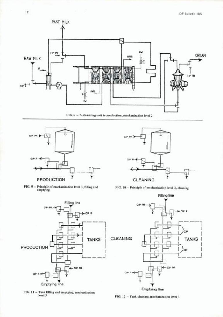
12 IDE Bulletin 185
P A
cip
21
Cu'
ci
1--
PAST. MILK
f
FIG. 8 - Pasteurizing unit in production, mechanization level 2
..., L f-k IN I (N PRODUCTION
r 1---L-
FIG. 9 - Principle of mechanization level 3, filling and emptying
Filling line CIP PR
--"
CIP R
TANKS
PRODUCTION I
L ~~A
cip R
CIP PR
Emptying line
FIG. 11 - Tank filling and emptying, mechanization level 3
FIG. 10 - Principle of mechanization level 3, cleaning
Filling line
cippR
— i—
—i
CLEANING F F 1 çii TANKS
I,cw
ciP R
Emptying line
FIG. 12 - Tank cleaning, mechanization level 3
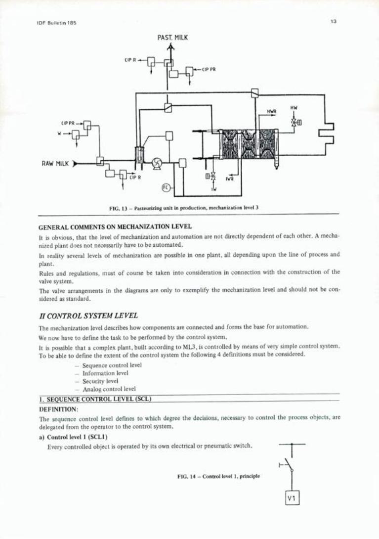
tDF Bulletin 185 13
PAST. MILK
RAW Mu
FIG. 13 - Pasteurizing unit in production, mechanization level 3
GENERAL COMMENTS ON MECHANIZATION LEVEL It is obvious, that the level of mechanization and automation are not directly dependent of each other. A mecha- nized plant does not necessarily have to be automated. In reality several levels of mechanization are possible in one plant, all depending upon the line of process and plant. Rules and regulations, must of course be taken into consideration in connection with the construction of the valve system. The valve arrangements in the diagrams are only to exemplify the mechanization level and should not be con-sidered as standard.
H CONTROL SYSTEM LEVEL The mechanization level describes how components are connected and forms the base for automation.
We now have to define the task to be performed by the control system. It is possible that a complex plant, built according to ML3, is controlled by means of very simple control system. To be able to define the extent of the control system the following 4 definitions must be considered.
Sequence control level - Information level - Security level - Analog control level
1. SEQUENCE CONTROL LEVEL (SCL)
DEFINITION: The sequence control level defines to which degree the decisions, necessary to control the process objects, are delegated from the operator to the control system.
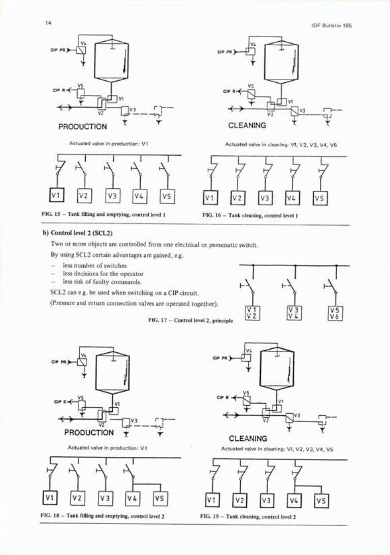
a) Control level 1 (SCLI) Every controlled object is operated by its own electrical or pneumatic switch.
F-
FIG. 14 - Control level 1, principle
vi I
OF
C
CIP
Cl
I--- 13 rm--
t PRODUCTION
CIP PR
CIP
PRODUCTION V3
t
CIP I
CLEANING Actuated valve in cleaning: Vi, V2, V3, V4, V5
14 IDF Bulle1n 185
Actuated valve in production: Vi Actuated valve in cleaning: Vi, V2, V3, V4, V5
cl I I V5 a F FIG. 15 - Tank filling and emptying, control level 1 FIG. 16 - Tank cleaning, control level 1
b) Control level 2 (SCL2)
Two or more objects are controlled from one electrical or pneumatic switch.
By using SCL2 certain advantages are gained, e.g.
- less number of switches - less decisions for the operator - less risk of faulty commands.
SCL2 can e.g. be used when switching on a CIP-circuit.
(Pressure and return connection valves are operated together). Vi V3 V5 V2 V4 V6 FIG. 17 - Control level 2, principle
Actuated valve in production: Vi
1 i V51 a V 3
FIG. 18 - Tank filling and emptying, control level 2 FIG. 19 - Tank cleaning, control level 2

IDF Bulletin 185
Control level 3 (SCL3)
Control of groups of objects, linked together by their function in the plant.
I
15
FIG. 20 - Control level 3, principle
CLEANING Actuated valve in cleaning: VI, V2, V3, V4, V5 operated by one function switch
V2
t PRODUCTION
Actuated valve in production: Vi operated by one function switch
In SCL3 type control systems advantages are the same as in SCL2 but furthermore we have the possibility to
start up a complete function - control certain objects from more than one function.
V4
C1PPR)_—L 1
-
c*P
vs C1PR.E-1fl vi
Control level 4 (SCL4)
Sequential control of objects. This means that the command to start a function is given by the operator, but the control of the actual objects is performed by
- time dependent step-by-step controllers - sequence operations depending on timer and/or process signals.
Typical functions, controlled by a SCL4 system could be a filling of a tank or control of a CIP-unit.
FIG. 23 - Fifing of tank, control level 4
FIG. 21 - Tank filling and emptying, control level 3 FIG. 22 - Tank cleaning, control level 3
r -- -

16 IDF Bulletin 185
The operator starts the function and valve Vi will open. When the valve is opened (controlled by feed-back signal from the valve) pump P1 will start.
The agitator is started when medium level (LSM) is reached. The filling function is stopped when high level (LSH) is reached or the operator stops the function.
PAST. MILK
w
RAW Mu
FIG. 24 - Starting up of pasteurizer, control level 4
The operator starts the function and the pasteurizer is filled up with water and then put into circulation. The heating is started and when the right temperature is reached the cooling is started. When the temperatures are stabilized milk is taken in and the water is drained out. When the pasteurizer is completely filled with milk it is ready for production.
e) Control level 5 (SCLS)
Sequential control of functions.
This means, that the commands by the operator, comprising several functions, are stored and then executed in a predetermined way.
Examples of SCL5 options:
Synchronization of functions around a pasteurizer:
Transport of milk from supplying tanks to the pasteurizer at the right moment. Transport of milk and/or cream from the pasteurizer into receiving tanks.
- Filling of several tanks in a preselected order.
- Cleaning of several tanks in a preselected order.
- Preselection of emptying and CIP of a tank.
2. INFORMATION LEVEL (IL)
DEFINITION
The information level tells us how much information that is available to the operator, enabling him to read out the status of the plant.
Three main blocks must be considered:
The information about objects and functions (A).
The information about process (B).
- Arrangement of indication lights (C).
IDE Bulletin 185 1]
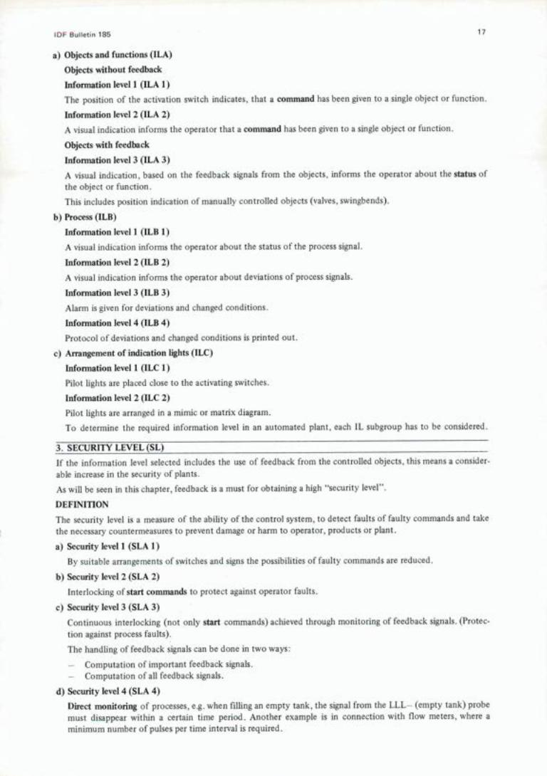
Objects and functions (ILA)
Objects without feedback
Information level 1 (ILA 1)
The position of the activation switch indicates, that a command has been given to a single object or function.
Information level 2 (ILA 2)
A visual indication informs the operator that a command has been given to a single object or function.
Objects with feedback
Information level 3 (ILA 3)
A visual indication, based on the feedback signals from the objects, informs the operator about the status of the object or function.
This includes position indication of manually controlled objects (valves, swingbends).
Process (ILB)
Information level 1 (ILB 1)
A visual indication informs the operator about the status of the process signal.
Information level 2 (ILB 2)
A visual indication informs the operator about deviations of process signals.
Information level 3 (ILB 3)
Alarm is given for deviations and changed conditions.
Information level 4 (ILB 4)
Protocol of deviations and changed conditions is printed out.
Arrangement of indication lights (ILC)
Information level 1 (ILC 1)
Pilot lights are placed close to the activating switches.
Information level 2 (ILC 2)
Pilot lights are arranged in a mimic or matrix diagram.
To determine the required information level in an automated plant, each IL subgroup has to be considered
3. SECURITY LEVEL (SL) -
If the information level selected includes the use of feedback from the controlled objects, this means a consider-able increase in the security of plants.
As will be seen in this chapter, feedback is a must for obtaining a high "security level".
DEFINITION
The security level is a measure of the ability of the control system, to detect faults of faulty commands and take the necessary countermeasures to prevent damage or harm to operator, products or plant.
Security level 1 (SLA 1)
By suitable arrangements of switches and signs the possibilities of faulty commands are reduced.
Security level 2 (SLA 2)
Interlocking of start commands to protect against operator faults.
Security level 3 (SLA 3)
Continuous interlocking (not only start commands) achieved through monitoring of feedback signals. (Protec-tion against process faults).
The handling of feedback signals can be done in two ways:
Computation of important feedback signals. - Computation of all feedback signals.
Security level 4 (SLA 4)
Direct monitoring of processes, e.g. when filling an empty tank, the signal from the LLL— (empty tank) probe must disappear within a certain time period. Another example is in connection with flow meters, where a minimum number of pulses per time interval is required.

18 IDE Bulletin 185
ACTIONS TAKEN BY THE CONTROL SYSTEM
Security level 1 (SLB 1)
Complete reset of all output signals.
Security level 2 (SLB 2)
Complete reset of all output signals in the actual function.
Security level 3 (SLB 3)
Selective reset of output signals to avoid unnecessary product losses, production stop, etc. Security level 4 (SLB 4)
Changing over to special emergency routines in order to recover product and minimize production interface.
4. ANALOG CONTROL LEVEL (ACL)
DEFINITION
The analog control level defines the degree of complexity of the analog control system. This level is determined by the type of process and the control requirements.
Control level 1 - Manual stations (ACL 1)
The control variables are controlled from manual stations without feedback.
Example: Control of cooling water for a pasteurizer using a hand valve.
Control level 2 .- Simple feedback loops (ACL 2)
Every control variable is measured and controlled by its own controller. This level may include controllers in cascade.
Example: Control of pasteurization temperature by a pneumatic or electric PlD-controller. Control level 3 - Remote setpoint and parameter control (ACL 3)
The same as level 2 but the control parameters and/or the setpoints are determined by a central controller. The values of the parameters and setpoints may be altered several times during operation.
Example: The setpoint of the steam pressure controller for a multipurpose pasteurizer. Control level 4 - Computer control (ACL 4)
All controllers are programmed into the computer. At this level it is possible to use non standard controllers like e.g. self-tuning controllers and multivariable controllers.
Example: Some process characteristics may slowly change in time. Improved control action may then be achieved with a self-tuning controller, which automatically adjusts its own parameters.
If one computer is used for a number of control ioops, one has to consider the back-up possibility if the computer is out of function.
B. SYSTEMS AVAILABLE FOR AUTOMATION
Historical definition
Traditionally control systems were divided into two categories Hardwired and Programmable.
Hardwired means that the system is built up by simple components like relays or electronic modules which are linked together with wires. These wires determine the function of the system.
Programmable means that the system contains an electronic memory that includes the specific program (func-tion) for a plant. The hardware of the system is standard and independent of how the system is used. Tradi-tionally one divided the systems into programmable controllers, micro computers and mini computers.
Definition valid 1984
Depending on the technical development one may today suggest the following rough grouping of systems.
Relay systems that are still used for certain applications with relatively low automation level.
Dedicated control systems e.g. an analogue controller. These systems may be built up by using mechanical solu-tions and electronics. The trend is to use microelectronics more and more.
Programmable control systems have gone through a rapid development and independent of application they are all built up by micro electronics. All systems contain one or more micro computers.
DF Bulletin 185 19
Control problems and relevant technical solutions.
In the dairy industry one can find basically three types of control tasks, sequence control, analogue control and management control.
Sequence control can be implemented with a hardwired relay control system but much more often with so-called programmable logic controllers (PLC). A range of systems are available on the market from very small and simple systems up to very sophisticated systems.
Analogue control can be implemented with conventional analogue controllers but also with programmable systems dedicated for complex control tasks. In addition to microcomputers the more advances PLC's can also handle analogue control.
Management control requires some kind of programmable system. The advanced analogue control systems very often offer management functions like trend information, data logging, etc. The more advanced PLC's have similar options like production reporting, recipe handling, etc.
TRENDS The dividing line between systems will gradually disappear, especially for the larger, programmable systems. Small dedicated systems based on microelectronics, but not easily reprogrammable, will always be available (e.g. the micro computerized stove). The applications include, for example, milk standardization, cheese vat control and freezer control.
Another trend is that the original PLC has grown substantially in capacity and performance. The name PLC now incorporates control systems earlier implemented by both the small, original PLC, and also the micro- and the minicomputers. A PLC today can therefore indicate a control system of any size. Its performance and price must be evaluated from its technical particulars and not from its name "PLC".
For the future we suggest that a better word be used for these kinds of flexible, easily reprogrammable systems. The word PLC actually indicates a limitation as the letter "L" stands for "logic" only.
And even though PLC's today are microcomputer systems (or microprocessor systems if we prefer that word), the denomination microcomputer or microprocessor does not always mean an easily programmable system (e.g. the computerized stove).
We therefore suggest that the word "PC systems" programmable control systems, be used.
PC system = programmable control system based on microprocessor technology and easily repro-gramnrnable. Performance and capacity according to the technical particulars of each specific system.
Microprocessor = the central unit of a computer built into one single component ("chip").
Microcomputer = A computer system based on one or several rriicroprocessors.
C. ALTERNATIVE MODELS FOR OPERATOR COMMUNICATION AND SYSTEM ARCHITECTURE Operator Consoles
Man-machine communication requires an operator console with an indicator unit. According to the decisions made by the operator process functions are initiated via the operator console, e.g. starting or stopping routes, or starting or stopping cleaning programs.
The requests and conceptions of the respective user must be taken into consideration when deciding whether the operational control should be centralized or decentralized, as this decision is closely connected with his areas of responsibility.
Centralized operation can be carried out either from a free-standing desk or from switches and pushbuttons in the door of the panel.
Decentralized operation is often carried out via subpanels. These must be waterproof when located in wet areas. The casings can be made of stainless steel or plastics.
Units which have a display screen with text programs or graphic symbols are only operated in combination with programmable controllers (PC's).
With the support of a printer it is possible to make process reports as well as fault reports.
An information unit, such as a lamp array, a mimic or a lamp matrix, can be installed at the operator's desk or, provided it is only a small unit, in the door of the control panels. In large control systems the unit is free-standing and combined with an instrument panel.

20 IDE Bulletin 185
The instrument panel includes distributed controllers needed in the control system (e.g. temperature controller), as well as recorders and the indicators (e.g. for tank contents, temperatures and pH).
Location
Controls are not always installed at the most favourable location. Not only tanks but also control systems require space.
Small control systems are frequently installed in the process rooms, and in such situations the control cabinets must be made of stainless steel and be waterproof. In spite of the latter it must be observed that the control cabinet must not be installed in an area constantly exposed to spray water or steam, especially as the door might at time be open.
Large control systems are normally set up in an air-conditioned control room, which is separated from the process rooms, and where the operator works in a normal office environment.
Control panels I instrument panels
Remote control was first implemented via control panels with pushbuttons and indication lamps. This type of configuration still has its place in small applications with a few control signals to run the process area involved and possibly to communicate with a superior system.
The instrument section, installed in the control panel or built as a separate instrument panel normally incor-porates indicators, recorders and distributed analog controllers for temperature, pressure, pH, etc.
The panels are normally made as painted or stainless steel cabinets. The equipment must be able to withstand the process environment if necessary.
Printer terminal with keyboard
The printer terminal is commonly used in conjunction with programmable controllers (PC's). When dealing with larger control tasks, the printer terminal is normally better suited than an ordinary pushbutton panel due to:
smaller space requirements
cost
flexibility of expansion due to
- single cable connection to PC (serial link) keyboard and printer can be used for any type of commands/messages.
Today, the printer keyboard is commonly used for hard-copy reports, for program modification and for entering new control commands to the system.
The latter function is often a stand.by one, other operator terminals being used for the actual routine process control (e.g. VDU).
Visual display unit (VDU)
The visual display unit (TV-screen) is today often used as the operator's tool for process control.
It offers a keyboard just like the printer terminal but also a TV-screen where different images can be built, e.g. the process mimic and statistical diagrams for management reports.
The VDU offers all the features of the printer terminal to an even greater extent. But the cost is higher and very much dependent on the internal programs for running the terminal (image building, modification of images, etc.). Standardization is very important to bring down costs.
VDU's can be either black and white or colour. The B & W version is cheaper but the colour system is more effective in presenting information to the operator.
Purpose-built operator stations
Keyboards
The ordinary keyboard, like the one in a typewriter, is commonly used to enter new commands into a program-mable control system.
However, one drawback is that the different commands must be entered by punching in each letter, one by one, before the PC system accepts the command.
This drawback may be eliminated by designing purpose-built keys, each corresponding to a certain process item, function or command. For example instead of punching in S—T—A---R—T, the key named START is depressed.
The keyboard can also be divided into several groups of keys to get a more ergonomic design. A further step is to incorporate a display unit that immediately confirms each depression.
IDF Bulletin 185 21
The keyboard may be designed in both desk-top and panel versions, in the latter case with hose-proof or water-proof housings.
Process display units
The process display unit informs the operator quickly and clearly about the operational conditions of the plant as well as about possible malfunctions. In small systems this unit may merely consist of indicator lamps and push-buttons, in larger systems of an illuminated mimic diagram, a lamp matrix system or a visual display unit (VDU) with a connected printer.
The mimic is often arranged in either a mosaic or back-painted single sheet configuration. It is easy to keep track of as the total process is indicated by symbols. In the lamp matrix system lamps are arranged in coordinates and indicate the process functions in operation instead of individual process objects. It is clearly easy to extend although it does not give a pictorial representation of the process plant provided either by a mimic or a VDU system.
PC = programmable controller
D. ITEM NUMBERING SYSTEM The system described is one type of logical numbering system.
Definition
In an automated plant there are different types of electrical and mechanical components and equipment involved with different tasks.
For maintenance purpose, which means understanding, trouble-shooting and spare parts purchase, all com-ponents and equipment must be readily identified.
This is done by assigning each item an individual item number, which serves as identification in diagrams, equipment, lists and on the equipment itself.
Basic philosophy
The way to build up a logical item numbering system will be shown by an example.
A very common case today is that on a tank we find a valve V988, an agitator motor Ml 23 and a high level switch HL14. The tank is called 14.
This will be improved if we change the numbers:
V988 = 14.V8 M123 = 14.Ml HL14 = 14.1_1
Now the item-number 14.V8 gives us more information about the function of the valve. We can easily see that tank 14 is involved. With possibly thousands of valves this is a big improvement from a maintenance point of view.
Initially there may be only (say) 8 valves associated with tank 14. If the system is subsequently expended and extra valves added we would use item numbers 14.V9, 14.VlO ......etc.
Of course the valve with the same function in tank 15 is called tank 15.V8 which is also an aid during main-tenance.
Thus by splitting item up into functional group we make things easier.
Correlation block
The same philosophy can be used for numbering the tanks.
Suppose tanks 10 to 14 are raw milk tanks and tanks 15 to 18 are skimmilk tanks.
This will then change:
14 = R4 15 = Si
We see that the numbers also tell us the function.
Extensions can easily take place. For example the next raw milk tank will be R5.
The new number V988 will thus be R4.V8.
If the plant is big even more elements may be used.
Example: Y.R4 will be the raw milk tank in the yogurt part.

22 IDF BuIIetn 185
The first element to the number will show "part of the plant"
Example: B = butter I = ice cream M = milk treatment Q = quarg U = utilities Y = yogurt
The second element will show "area of the part"
Example: C = cleaning F = filling P = pasteurization R = raw milk tanks
The third element will show "process object in the area"
Example: V = valve equipment L = level equipment M = motor equipment T = temperature equipment
The number explained so far is used to show the correlation of different components.
The correlation block is also called "higher level designation" and has its qualifying symbol
The number will be = Y.R4.V8
Item identification block
All components included to the function of this valve will now be related.
Example: = Y.R4.V8 - Yl - solenoid valve = Y.R4.V8 - Si -* manual switch = Y.R4.V8 - Bi -* micro switch
The item number block with its qualifying symbol is called the "item identification".
Also here we sometimes find the number divided into several groups.
Example: - Qi .K2
Q2 - power circuit breaker equipment K2 - contactor in this equipment
Location block
We must not forget that especially for electronic equipment the location of an item is very important not only during production and installation.
The number = Y.RT4.V8—Yl is very nice to find on the solenoid valve when you have found the valve. It is sometimes also necessary to have a reference to the location.
The number of this solenoid valve may then look like
+ SB5.Y4
where + is the qualifying symbol for the location and SBS means solenoid valve box No 5 and Y4 means position 4 inside the cabinet.
An example of the use of the item numbering system
The use of qualifying symbol in front of the different numbers is necessary to explain what kind of number it is.
Example: = Y.Pl Ml means the yogurt part pasteurizer 1 homogenizer equipment 1
This equipment is built up by different items.
- Qi .K2 means power circuit breaker equipment contractor 2
In documentation and on the equipment itselves we can use these numbers.
Example: = Y.P1.M1—Q1 is marked on the breaker equipment.
For electrical equipment especially they are often placed together in cabinets and it is not always easy to
IDF Bulletin 185 23
locate a special relay or card.
The number = Y.P1.Ml—Ql.K2 is functionally oriented and gives no information where it is located.
When needed, the location block therefore can be added to the item number.
Example: + MCC5.1 .2.3 means motor control cabinet No 5 section No 1 row No 2 place No 3
Of course just + MCC5 may be enough.
The different blocks give all information necessary and shall be used properly in documentation and in the plant.
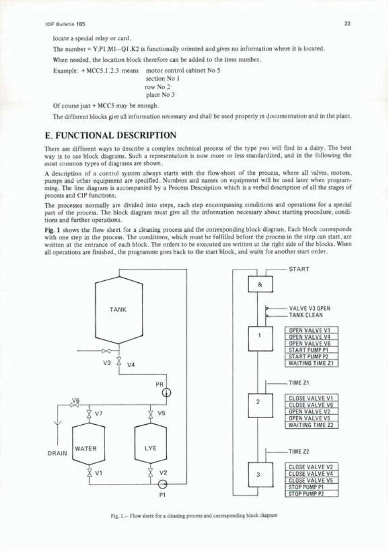
E. FUNCTIONAL DESCRIPTION There are different ways to describe a complex technical process of the type you will find in a dairy. The best way is to use block diagrams. Such a representation is now more or less standardized, and in the following the most common types of diagrams are shown. A description of a control system always starts with the flow-sheet of the process, where all valves, motors, pumps and other equipment are specified. Numbers and names on equipment will be used later when program-ming. The line diagram is accompanied by a Process Description which is a verbal description of all the stages of process and CIP functions. The processes normally are divided into steps, each step encompassing conditions and operations for a special part of the process. The block diagram must give all the information necessary about starting procedure, condi-tions and further operations. Fig. 1 shows the flow sheet for a cleaning process and the corresponding block diagram. Each block corresponds with one step in the process. The conditions, which must be fulfilled before the process in the step can start, are written at the entrance of each block. The orders to be executed are written at the right side of the blocks. When all operations are finished, the programme goes back to the start block, and waits for another start order.
START
VALVE V3 OPEN TANK CLEAN
OPEN VALVE Vi OPEN VALVE V4 OPEN VALVE V6 START PUMP P1 START PUMP P2 WAITING TIME Zi
TIME Zi
CLOSE VALVE Vi CLOSE VALVE VB OPEN VALVE V2 OPEN VALVE V5 WAITING TIME Z2
TIME Z2
CLOSE VALVE V2 I CLOSE VALVE V4 I_CLOSE VALVE V5
OP PUMP P1 I STOP PUMP P2
P1
Fig. 1.— Flow sheet for a cleaning process and corresponding block diagram

24 IDF Bulletin 185
Fig. 2 shows another type of diagram, which is useful when the control system has to choose one of two possibi-lities, depending on signals from the process. The flow sheet shows a tank which can be filled by opening valve Vl and starting a pump P1. The filling can be stopped by means of a pressbutton. A level controller at the top of the tank stops the filling when the tank is full and a message is written at the control desk. The sharp-ended blocks sympolize questions, where the answers are "yes" or "no". A block can only answer one question, and for each additional question at the same point, another block has to be added. The square blocks symbolize orders, and one block can contain more orders. Diagrams of this type must be prepared by people with a full knowledge of the Process Description.
From the diagrams the control engineer can now design the hardware, and make the computer programmes
LEVEL N DI CATO R
P1 Vi
Fig. 2.— Block diagram describing automatic filling of a tank
IDF Bulletin 185 25
V. ORGANIZATION AND EXECUTION A. ALTERNATIVE ASPECTS FOR ORGANIZING AN AUTOMATED DAIRY
GENERAL Up to now it has been common practice to combine all operations and controls of a plant in a single process control, even when individual departnients were operating with decentralized subpanels.
in the following, an alternative philosophy has been developed to establish dairies split-up in to responsibility areas each with their own control systems.
Process Lines with Dedicated Control Systems
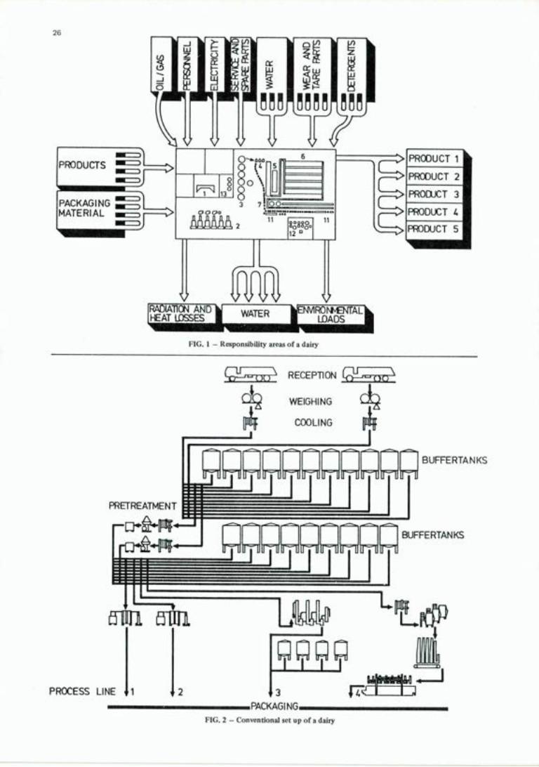
Traditionally the dairy process is operated and controlled by responsibility areas as shown in Fig. 1 . In these areas production is considered as one unit and the total requirements for fuel oil, personnel, electricity, services and spare parts, water, detergents, shipping and packaging material as well as environmental loads etc. are meas-ured for the entire production.
If an individual product or a single process line is to be properly controlled and analysed facilities must be created to assign raw materials, energy supply, personnel, losses and environmental loads to these individual production lines, i.e. the conventional areas of responsibility, which are shown in Fig. l,will have to be abandoned.
The attempt should be made to design process lines to function as simply and clearly as possible, i.e. production plants for individual products and products families should be constructed.
Following along these lines and in agreement with the above-mentioned concept of assigning input and output to the individual process lines, the conventional set up of a dairy plant as shown in Fig. 2 must be abandoned, and instead individual process lines as proposed in Fig. 3 must be arranged.
This rationalization of production lines will result in a reduction of tank capacities and also in a reduction in valves operated by remote control, both of which are essential to reduce production losses. This makes possible a complete drainage of the process line before cleaning operations, not only draining off the products but also the water in order to avoid or keep at a minimum the water mixing with either the product or the detergent.
On the other hand the reduction of tank capacities requires more careful production planning.
The control of such a specialized process is relatively simple as no communication with any other product lines need be considered. Operation of a process line with a predetermined technology and a fixed time schedule can be documented via production and consumption figures. These data can be used for future adjustment and opti-mization of the plant. This documentation can also be used for production planning in connection with energy supply and storage arrangements.
Preventive maintenance for such a process and its machinery can be planned with the aid of the recorded data, through which the stocks of spare parts can be reduced. Finally the production costs can be ascertained as a criterion for the economic conduct of the process.
Experience has shown that it pays to set up an individual line for a certain product or a product family, pro-vided this product reaches 25 to 3017r, of the total production volume of a plant.
A split-up in individual production processes has the additional advantage that the raw material "milk" can be fed into the individual process lines according to its composition.
When applying this system each process line may have its own specially assigned cleaning station (fig. 5), instead of the more conventional centralized CIP system (fig. 4).
Process Control According to the idea, as outlined above, of optimizing a dairy plant by a split-up into individual process lines, it is logical to equip the individual process lines with their own process controls with only the minimum necessary communication between the individual control systems. The process controls of the individual process lines may be quite differently set up as far as hardware and software are concerned. All control systems are able to commu-nicate with a central computer, which receives the data and gives commands that were until then initiated by the operator.
26
Ur 4.1 N iI (III.LllJ.klldJ1L11 I Io 6
PRODUCTS _
IJ
2
PACKAGING — 11308I
MATERIAL OOGO
2 11 11
I ---)
I12F'
PRODUCT 1
PRODUCT 2
PRODUCT 3
PRODUCT 4
PRODUCT 5
IRADIATION AND WATER OvrAtjk IHEAT LOSSES J LOADS I
FIG. 1 - Responsibility areas of a dairy
(Th \ I-' REEP11ON
WEIGHING
o4 COOLING
B UFFERTA N KS
PRETREATMENT
BUFFERTANKS
11
LW I
PROCESS LINE 1 2 3 I ZIIrJ PACKAGING
FIG. 2 - Conventional set up of a dairy

.-
elu. 'i - convenuonas centrauzed CIP
IDE Bulletin 185
FI RECEPTION
WEIGHING
COOLING
ri ILOTANKS
r1 ri PRETREATMENT £ . IIIII. ;r
BUFFER-
Lurm
27
F1OCESS LINE II
610101
3
PACKAGING
FIG. 3 - New concept for the set up of a dairy

28 IDE Bulletin 185
RAW MILK
RLLING We CNQ
\FIwNG " e o e e
' FILLING \
ç \ FIWNG \
\
FIG. 5 - New decentralized CIP system
111-le NO
F1WNG \\
\
B. ORGANIZING AN AUTOMATION PROJECT
GENERAL
In the operation of an extensively automated production plant automation today plays such a significant role that as much attention must be paid to its planning as to the planning of process and other systems. Co-operation with process planning, construction planning, electrical planning and other types of planning has to be continuous and more intensive than is traditionally the case. Even the selection of suppliers of automation systems should be carried out at an early stage, in the preparatory phase of the project, so that their work input can be utilized as fully as possible.
Planning automation is a particularly engrossing part of a project, in which both users and process planners ought to show interest. However, even if automation planning has become a separate activity, it should not exclude planners from other areas. On the contrary, the rapid expansion of automation has made its planning a complex task, in which close co-operation is required. For example, certain key decisions such as drift method solutions, control room lay-out and the determination of the manning requirements of the plant call for joint decisions by several other planners and future users.
Well-organized project co-operation builds a sound foundation for these matters.
WHAT IS A PROJECT?
The characteristics of a project are that it is defined in time, in financial terms, in content and in extent, and is carried out by a precisely defined staff organization. Project work requires an organized operation, in which teclmical planning and realization take place under strict guidance and control.
As was mentioned above a project includes two separate groups of tasks which are:
- the actual technical planning and realization of the project; - management and co-ordination of tasks, information exchange and project personnel.
This systematic way of giving tasks for carrying out the project ensures the participation of specialists from all different fields in the project. In this way it is also possible to make sure that the outcome will be an auto-mated process that lies within the bounds of previously set time and cost limits and that it works to the satis-faction of the buyer.
IDF Bulletin 185 29
THE MAIN AREAS IN AUTOMATION PLANNING AND REALIZATION
The planning and realization of an automation project can be divided into the following main areas:
- equipment hardware and software planning instrumentation
- control room equipment installation
In an integrated automation system, none of the areas are independent so that they cannot be planned separa-tely. The more advanced the automation system being planned the more integrated must be the planning work for different areas. In order to achieve the overall aims set for system planning, it has to be carried out as an entity.
The division of work into planning areas just described is not intended to be universally applicable. The proper distribution of duties is determined by the particular characteristics of each planning objective such as:
-- structure of the automation system - technologies and equipment used - available staff
the organization carrying out the project.
Nevertheless, it seems valid to maintain that the task of automation planning described above forms a single entity. The more advanced the automated plant being planned and the more integrated the system solution used, the more important becomes the co-ordination of the planning work as an organizational whole.
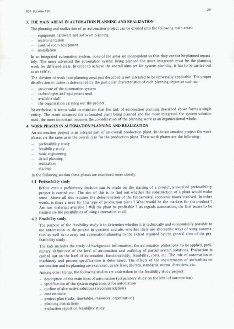
WORK PHASES IN AUTOMATION PLANNING AND REALIZATION An automation project is an integral part of an overall production plant. In the automation project the work phases are the same as in the overall plan for the production plant. These work phases are the following:
prefeasibility study - feasibility study - basic engineering - detail planning - realization - start.up
In the following section these phases are examined more closely.
4.1 Prefeasibility study Before even a preliminary decision can be made on the starting of a project, a so-called prefeasibility project is carried out. The aim of this is to find out whether the construction of a plant would make sense. Above all this requires the determination of the fundamental economic issues involved. In other words, is there a need for this type of production plant ? What would be the markets for the product ? Are raw materials available ? Will the plant be profitable ? As regards automation, the first issues to be studied are the possibilities of using automation at all.
4.2 Feasibility study The purpose of the feasibility study is to determine whether it is technically and economically possible to use automation in the project in question and also whether there are alternative ways of using automa-tion as well as to carry out automation planning to the extent required by the general aims of the pre-feasibility study. The task includes the study of background information, the automation philosophy to be applied, preli-minary definitions of the level of automation and outlining of partial system solutions. Evaluation is carried out on the level of automation, functionability, feasibility, costs, etc. The role of automation in machinery and process specifications is determined. The effects of the requirements of authorities on automation and its planning are examined, as are laws, decrees, standards, norms, directives, etc.
Among other things, the following studies are undertaken in the feasibility study project:
- description of the main lines of automation (preparatory study on the level of automation) - specification of the system requirements for automation - outline of alternative solutions (recommendation) - cost estimate - project plan (tasks, timetables, resources, organization) - planning instructions - evaluation report on feasibility study

30 IDF BuIIetn 185
4.3 Basic engineering
The studies carried out during the feasibility study phase form the basis for the basic engineering of the project. The application of this basic rule is particularly important because the profitability of the plant to be constructed depends on decisions and technical solutions made in the feasibility phase.
Regrettably all too often production plant projects are implemented in which the basic solutions made in the feasibility study phase are not applied or in which the feasibility study has been carried out carelessly. Initial information for basic engineering is obtained from the following sources:
- information from the feasibility study project - commission for the planning and realization of automation - procurement contracts on process equipment and machinery - flow charts - process description
information on other corresponding plants information on systems available
Basic engineering produces, among other things, the following information:
- directives for the realization of the automation project - final definition of the level of automation - process studies - P1—diagrams - description of controls - control room concept - process computer task description, system description - equipment specifications - tender bids and comparison - selection of automation equipment - main procurement contracts
4.4 Realization
This is the phase in which the detailed planning, manufacturing, assembling and installation of the equip-ment selected in the basic engineering phase takes place. Depending on the implementation method cho-sen (turn-key, own planning), part or all of the task in this phase may belong to the automation supplier. How extensively and deeply these issues are studied by the buyer of automation himself depends largely on the buyer's own resources.
In the following a number of matters connected with realization are discussed: - control room planning - process control equipment hardware and software and program planning - installation planning - installation and installation supervision
4.4.1 Control room planning
The aim of control room planning is the elaboration, specification, further development and realiza-tion of the control room plans made in the feasibility study and basic engineering phase. Along with the development of plans, the definitions arrived at in preplanning and basic engineering are ela-borated. The planning of the lay-out of the control room is made more precise. The technical equip-ment for the control room is studied. Process charts and the lay-out of boards, panels, desks, tables and instruments on tables are planned. The equipment coming to the control room from other systems than process is examined (electricity, telecommunications, building automation, etc.). It is also necessary to consider the construction planning of the control room (fire protection, vibration, water danger, lighting, ventilation, passageways, surface materials, colours, furniture, audio-visual equipment). The information required for installation planning is acquired.
4.4.2 Process control equipment hardware and software planning
The aim of process computer planning is the elaboration, specification, further development and realization of the plans made in feasibility study and basic engineering. Along with the development of plans the definitions obtained from feasibility study and basic engineering are elaborated. The task definitions of the computer system are made more precise. The connections with other areas are studied.

IDE Bulletin 185 31
The task also includes the planning, procurement and realization of the complete computer system so that it constitutes a working system.
4.43 Instrumentation planning
The purpose of instrumentation planning (detail planning) is to come up with a fully defined auto-mation system with details of equipment and interconnections.
Basic engineering is elaborated and completed. The structural planning of partial systems and instruments, tunings, controls, shieldings etc. is carried out, including, i.a.:
- dimensioning of equipment, instruments and circuits equipment specifications by circuits
- coupling charts by circuits (current circuit charts) - planning of system assembly - coupling charts for auxiliary power supply system (current circuit charts) - acquisition of information required by installation planning
operation description reports of equipment, instruments installation, use and maintenance instruction for equipment, instruments and systems.
4.4.4 Installation planning
Installation planning relates to the assembly of instruments, equipment and systems on site (or in the factory) and also determines the necessary installation material.
Planning of the placement and location of equipment, i.a.:
the placement of measuring sensors and operating equipment in piping and machinery drawings - placement of field equipment in the lay-out drawings of the plant
placement of cabinets, cross coupling stands etc. in the lay-out drawings of the corresponding rooms planning and reservation of main cable routes.
Detailed planning of the process fittings for sensors and supportings for cables etc.
Installation planning of the signal network includes i.a.:
- installation planning of the electrical cable and pneumatic network and field terminal cabinets installation planning of the power supply system.
4.4.5 Installation and installation supervision
The task of installation includes all on-site assembly installation and connection work required. Installation supervision involves ensuring that work is carried out correctly throughout and that directives are adhered to: contact is kept with other parties and installation inspections are taken care of. The duties include, i.a.:
- installation or installation supervision of fittings - installation or installation supervision of field equipment - installation and installation supervision of cabinets, cross connection, desks, boards, panel, etc. - instrument installation and installation supervision of the control room - installation and installation supervision of communications network (pneumatic piping, wiring
and connections wires, cross connection - installation or installation supervision of the power supply system - inspection of installations
4.5 Start-up
The start-up of an automation system can roughly be divided into the following work phases:
inspection of equipment on reception
"cold" testing of systems and equipment
- control room - field
- "hot" testing of systems with the process
- functioning tests (water) - process performance tests (product)
During testing final tuning is carried out, and the functioning of the process and automation are tested as a whole. Inspection is carried out to ensure that the system fulfils the requirements set by the various specifications.

32 IDF Bulletin 185
In performance tests the performance values of the automation system and the process are verified in controlled conditions.
The results of the tests are documented and compared with target values. Deviations from target values are dealt with.
The test results make up the basic performance values for the plant, which form one basis for the long-term supervision of the use of the plant.
User and maintenance personnel are trained. Information is collected on the realization of the different work phases, and the experience acquired is put into a report.
5. PROCUREMENT
In general the implementation of every project calls for the acquisition of certain materials and/or services. Procurement consists of different partial tasks, which must be carried out in a planned fashion in order to achieve the best possible result.
5.1 There are four different approaches to procurement, depending on the size of the project, available personnel, financial resources and the project timetable. It is necessary already in the preplanning stage of the project to consider the way procurement is to take place in the realization of the project. Appendix 1 illustrates the most essential advantages and drawbacks for the customer contained in the different pro-curement approaches.
5.2 Carrying out procurement
In most cases it is necessary to start procurement planning already in the prefeasibility stage of the project. Before the decision is made on the realization of the project, it is necessary to examine the main princi-ples of automation connected with the project, the level of standards, preliminary control room and instrumentation spaces, manning, resource needs for planning and realization as well as the timetable of the project. On the basis of these studies, the decision-maker is given a proposal or a few alternatives with cost estimates on the procurement of automation. The actual realization decision usually lays down for the execution of the project a set timetable, cost estimate and an overall "framework" of the project. At this stage the method of automation procurement has at least preliminary to be decided upon. The actual procurement operation commences after the decision to carry out the project has been made.
5.2.1 Tender bids
The first partial task linked with procurement is to consider possible suppliers and ask for tenders. In most cases budget quotations have already been sought in the feasibility stage, possibly from several suppliers, so that moving over to the actual bid stage occurs without much difficulty.
Frictionless co-operation between different planning sectors is extremely important in the prepara-tion of tender bids,so that any linking and adjoining parts will be taken care of already at this stage.
In the actual tender bid it is necessary to specify as accurately as possible the automation system. In many cases it is nevertheless necessary to ask for tenders with relatively little information. In practice at least the following initial information should be available:
flow chart and process information - measurement, control and regulation
choice of equipment in principle.
In addition tender bids usually include the following documents:
- general purchase conditions - technical details of machinery and equipment deliveries - agreement on the organization of installation (when required)
instrument instruction - standards to be observed.
A tender bid which has been carried out as completely as possible speeds up the preparation of the offer, reduces the need for telephone conversations, telex messages and letters as well as facilitates the next phases of procurement.
5.2.2 Comparison of tenders
After the tenders are submitted, comparison is carried out. In principle this is divided into technical and commercial stages. In the comparison stage it is often necessary for the buyer and the prospec-tive suppliers to negotiate in order to make the tenders as comparable as possible as regards techno-logy, conditions of payment, possibilities for credit and delivery times. Generally at this stage the buyer starts to form a picture of the competitors in the "final lap".

IDE Bulletin 185 33
5.2.3 Final tenders
Already at the time the tenders are compared or right afterwards, the tenders are made ready for final agreement in negotiations with the prospective suppliers. At this stage the extent of the tender, price specifications, terms of payment, guarantees, delay penalties and other matters connected with the contract should be studied closely. Furthermore, the so-called commercial negotiations are carried out at this stage. After this the buyer is prepared to select a supplier.
5.2.4 Selection of supplier
In case the final tenders are equal as regards technology and price, the final decision may well be a rather arduous task. This stage often requires that attention be paid to the following points:
- earlier experiences with the suppliers in question reference plants or installations
- the capability of the suppliers of carry out training, start-up and the so-called after sales services the degree of domestic components included capability to take care of spare parts and servicing
- pricing behaviour during project.
Most of these considerations are based on experience, and before the final selection is made it is worthwhile to coflect all available information to aid decision-making.
5.2.5 Procurement contract
The actual procurement contract is prepared on the basis of the final tenders and related negotia-tions. The actual text of the agreement as well as the appendices to it depend very much on the company in question, so that what is presented below should be regarded only as typical.
Basis for procurement contract
Contents
§ 1 Object of contract § 2 Price and price linkages § 3 Terms of payment and collateral security § 4 Times of delivery § 5 Penalty for delays in delivery § 6 Force majeure reservations § 7 Laws, decrees and requirements of the authorities § 8 Guarantees and conditions for guarantees § 9 Technical co-operation § 10 Changes § 11 Installation § 12 Installation inspection § 13 Test run and delivery for production use § 14 Approval and reception of delivery § 15 Transfer of ownership § 16 Responsibility for damages § 17 Cancellation of contract § 18 Resolutions of differences of opinion § 19 Entering into force of contract
Appendices to the contract
- technical specifications and prices by pieces of equipment operation and performance guarantees
- delivery schedule for drawings and documents - agreement on the organization of installation - procurement program - technical details of machinery and equipment - insurance terms - contact persons
Generally the more precision and the more detail is put in the preparation of the procurement contract, the less will there be controversies during and after the delivery. Especially in cases where the delivery involves several contracts, there is every reason to be very precise in agreeing to deli-very times and to secure the handling of any linking parts.

34 IDF Bulletin 185
Appendix 1
Method of procurement Advantages Drawbacks When applicable
Automation delivered with Clear limits of supply and The customer cannot influence Complete delivery of production the process responsibility decisions and implementation plant
Customer needs no resources No control over delivery, Part process deliveries Planned with the process increased need for training, Instrumentation for machinery
Specifications have to be fully and equipment drawn up at the tame time as the plant's. Lack of informa- tion when ordering
Separate automation delivery Use of consultant's knowhow Customer has little influence When the customer has neither with the aid of consultant Need for own resources small No control over delivery, the knowhow nor the resources
increased need for training, needed. Limits of responsibility To help when ther isa peakload difficult to define of planning Need for more specification, agreements and more spare parts Contacts with other suppliers more complicated
Separate automation delivery Benefit from supplier's know- Customer has little influence As a subcontractor for process with the aid of a supplier how. Need for own resources Bound to supplier who can plan delivery contract
small. Little planning needed. Bound to one supplier's To benefit from a supplier's Clear division of labour, technology. knowhow in processes, planning
Danger of over-instrumentation etc. No control over delivery Much of specification needed.
Separate automation delivery according to customer's own plans
Overall control improved Customer's influence over final result decisive Good contact with equipment and process planners. Less need for planning. Knowhow remains in-house Reduced dependence on suppliers
Need for own resources grows Need to continually spread Out the work evenly Limits of responsibility and supply more complicated.
When own planning activities are desirable

IDF Bulletin 185 35
VI. GLOSSARY OF TERMS An exhaustive glossary of all the technical terms used in automation engineering is outside the scope of this study. Only those terms used and not explained in the text are therefore defined below.
Analogue Control The control of continuously variable parameters such as temperature, pressure, flow or level by a corresponding continuously variable signal to the control element.
Feedback The provision of information as to the state of a process as a controlled item to enable corrective action to be taken to achieve the desired state.
Hardware The equipment used in computer control systems or generally in an automation system.
Hardwired The means by which relay or electrical circuits are connected together to obtain the control logic. (The equivalent of software in a computer system).
Interface Generally regarded as the boundary between the computer and the outside world i.e. the process plant. The interface isolates the computer from the effects of plant electrical noise and is used to convert plant signals into levels suitable for the computer and vice versa.
Interlocking A sequence control system may have the feature that until one or more particular events or conditions have occurred or been established and triggered a ' go ' situation then another event cannot happen. This feature is known as interlocking.
P.I.D. - Control Proportional, Integral and Derivative Control - i.e. conventional 3 term control.
P. & I. Diagrams Process and Instrumentation Diagrams. A line diagram defining both the process and instrumentation equipment control loops for a process plant. Often called a Process Line Diagram although this strictly does not need to have the instrumentation loop details included.
Software The programs which instruct to computer or microcomputer hardware carry out its desired function.
The IDF Bulletin for 1984 includes the following publications:
168 - Somatic cell counting in milk
169 - Use of unmarketable milk on the farm
170 - World market for butter
171 - Addresses in Oslo on cheesemaking (MM Lenoir, Oterholm, Schipper) in English and French
172 - World market for ice-cream
173 - Consumption statistics for 1982
174 - Balance tanks for dairy effluents
175 - Interim cheese market report
176 - Computerized bulk milk collection (Toronto Workshop of September 1983)
177 - Quality assurance (means of promoting efficiency in dairying) in English and Spanish (proceedings of a Seminar in Valdivia, Chile, November 1983)
178 - General Code of Hygienic practice for the dairy industry
179 Fermented milks (Avignon Seminar, May 1984) in English and French
180 - Inventory of lDF/ISO/AOAC methods of analysis
181 - Methods for detecting mixtures of cow's, ewe's and goat's milk
182 - Thermization of milk; on farm use of membrane systems
183 - Progeny testing methods in dairy cattle (Prague Symposium, September 1984)
184 - Dairy effluents (Killarney Seminar, April 1983)
as well as 12 international standards of analysis (in English and French).
The above publications are still available from:
lDF General Secretariat, Square Vergote 41, 8-1040 Brussels, Belgium.
All publications are in English only, unless otherwise indicated.

MA

R1YAiWL! WEEEF MIA, I MI A III1ITI 1Ji1tRb! tail'
1991 ER A T1O N An international Force
for Progress in Dairying
M UffFWE Dynamisme et Progrès au Service de Ia Laiterie Mondiale
SCIENCE PRODUCTION OF MILK
ENGINEERING TECHNOLOGY ECONOMICS
ANALYSIS NUTRITION
SCIENCE PRODUCTION LAITIERE INGENIERIE TECHNOLOGIE ECONOMIE ANALYSE NUTRITION
TERMINOLOGY I TERM INOLOGIE
IDF, Square Vergote 41 1040 — Brussels, Belgium
FIL, Square Vergote 41 1040 — Bruxelles, Belgique
L rio: