Embed Size (px)
Citation preview
E 5.05001.01
Single Power Unit
BUM 60 S
Manual
Title Manual
Product Single Power Unit BUM 60 S
Version 5.05001.01
Status 2005-01-26
Copyright These operating instructions may be copied by the owner in any quantity but only for internal use. For other purposes these op-erating instructions and extracts thereof must not be copied or reproduced. Use and disclosure of information contained in these operating instructions are not permitted. Designations and company marks contained in these operating instructions may be brand names, the use of which by third par-ties for their own purposes may violate the rights of the holders.
Obligatory These operating instructions are part of the equipment/ma-chine. These operating instructions must be available to the op-erator at all times and must be in a legible condition. If the equipment/machine is sold or moved to a different location these operating instructions must be passed on by the owner to-gether with the equipment/machine. After any sale of the equipment/machine this original and all copies must be handed over to the buyer. After disposal or any other end of use this original and all copies must be destroyed.
When the present operating instructions are handed over, cor-responding sets of operating instructions of a previous version are automatically invalidated. Please notice that specifications/data/information are current values according to the printing date. These statements are not legally binding according to the measurement, computation and calculations. Baumüller Nürnberg GmbH reserves the right, in developing its products further, to change the technical specifications and the handling of the products concerned without prior notice.
No liability can be accepted concerning the correctness of the operating instructions unless otherwise specified in the General Conditions of Sale and Delivery.
Manufacturer Baumüller Nürnberg GmbH Ostendstr. 80 - 90 D-90482 Nürnberg Germany Tel. +49 9 11 54 32 - 0 Fax: +49 9 11 54 32 - 1 30 www.baumueller.de
Table of contents
1 Introduction . . . . . . . . . . . . . . . . . . . . . . . . . . . . . . . . . . . . . . . . . . . . . . . . . . . . . . . . . . . . . . 5
1.1 General information . . . . . . . . . . . . . . . . . . . . . . . . . . . . . . . . . . . . . . . . . . . . . . . . . . . 51.1.1 Functional description . . . . . . . . . . . . . . . . . . . . . . . . . . . . . . . . . . . . . . . . . . . . . . . . 61.1.2 Block diagram. . . . . . . . . . . . . . . . . . . . . . . . . . . . . . . . . . . . . . . . . . . . . . . . . . . . . . . 7
2 Safety instructions . . . . . . . . . . . . . . . . . . . . . . . . . . . . . . . . . . . . . . . . . . . . . . . . . . . . . . . . 9
2.1 Qualified personnel. . . . . . . . . . . . . . . . . . . . . . . . . . . . . . . . . . . . . . . . . . . . . . . . . . . 102.2 Specified application. . . . . . . . . . . . . . . . . . . . . . . . . . . . . . . . . . . . . . . . . . . . . . . . . . 112.3 Voltage check . . . . . . . . . . . . . . . . . . . . . . . . . . . . . . . . . . . . . . . . . . . . . . . . . . . . . . . 11
3 Packing and Transportation. . . . . . . . . . . . . . . . . . . . . . . . . . . . . . . . . . . . . . . . . . . . . . . . 13
4 Mounting . . . . . . . . . . . . . . . . . . . . . . . . . . . . . . . . . . . . . . . . . . . . . . . . . . . . . . . . . . . . . . . 15
4.1 Dimensions . . . . . . . . . . . . . . . . . . . . . . . . . . . . . . . . . . . . . . . . . . . . . . . . . . . . . . . . . 164.2 Mounting note . . . . . . . . . . . . . . . . . . . . . . . . . . . . . . . . . . . . . . . . . . . . . . . . . . . . . . . 17
5 Installation . . . . . . . . . . . . . . . . . . . . . . . . . . . . . . . . . . . . . . . . . . . . . . . . . . . . . . . . . . . . . . 19
5.1 Safety notes . . . . . . . . . . . . . . . . . . . . . . . . . . . . . . . . . . . . . . . . . . . . . . . . . . . . . . . . 195.2 EMC instructions. . . . . . . . . . . . . . . . . . . . . . . . . . . . . . . . . . . . . . . . . . . . . . . . . . . . . 215.3 Connection plan BUM 60 S . . . . . . . . . . . . . . . . . . . . . . . . . . . . . . . . . . . . . . . . . . . . 285.4 Connection instructions . . . . . . . . . . . . . . . . . . . . . . . . . . . . . . . . . . . . . . . . . . . . . . . 295.5 Connector- and terminal assignment . . . . . . . . . . . . . . . . . . . . . . . . . . . . . . . . . . . . . 315.5.1 Power connections. . . . . . . . . . . . . . . . . . . . . . . . . . . . . . . . . . . . . . . . . . . . . . . . . . 315.5.2 Connector assignment . . . . . . . . . . . . . . . . . . . . . . . . . . . . . . . . . . . . . . . . . . . . . . . 325.6 Accessories . . . . . . . . . . . . . . . . . . . . . . . . . . . . . . . . . . . . . . . . . . . . . . . . . . . . . . . . 32
6 Commissioning . . . . . . . . . . . . . . . . . . . . . . . . . . . . . . . . . . . . . . . . . . . . . . . . . . . . . . . . . . 33
6.1 Safety notes . . . . . . . . . . . . . . . . . . . . . . . . . . . . . . . . . . . . . . . . . . . . . . . . . . . . . . . . 336.2 Operation . . . . . . . . . . . . . . . . . . . . . . . . . . . . . . . . . . . . . . . . . . . . . . . . . . . . . . . . . . 356.3 Messages and warnings . . . . . . . . . . . . . . . . . . . . . . . . . . . . . . . . . . . . . . . . . . . . . . . 356.3.1 Monitoring of infeed converter . . . . . . . . . . . . . . . . . . . . . . . . . . . . . . . . . . . . . . . . . 356.3.2 Monitoring motor-sided inverter . . . . . . . . . . . . . . . . . . . . . . . . . . . . . . . . . . . . . . . . 366.3.3 Error messages . . . . . . . . . . . . . . . . . . . . . . . . . . . . . . . . . . . . . . . . . . . . . . . . . . . . 37
7 Maintenance . . . . . . . . . . . . . . . . . . . . . . . . . . . . . . . . . . . . . . . . . . . . . . . . . . . . . . . . . . . . 41
7.1 Maintenance notes . . . . . . . . . . . . . . . . . . . . . . . . . . . . . . . . . . . . . . . . . . . . . . . . . . . 417.2 Storage conditions . . . . . . . . . . . . . . . . . . . . . . . . . . . . . . . . . . . . . . . . . . . . . . . . . . . 427.3 Recommissioning . . . . . . . . . . . . . . . . . . . . . . . . . . . . . . . . . . . . . . . . . . . . . . . . . . . . 427.4 Disposal . . . . . . . . . . . . . . . . . . . . . . . . . . . . . . . . . . . . . . . . . . . . . . . . . . . . . . . . . . . 43
Appendix A - Abbreviations . . . . . . . . . . . . . . . . . . . . . . . . . . . . . . . . . . . . . . . . . . . . . . . . . . 45
Appendix B - Technical data . . . . . . . . . . . . . . . . . . . . . . . . . . . . . . . . . . . . . . . . . . . . . . . . . . 47
B.1 Required environmental conditions . . . . . . . . . . . . . . . . . . . . . . . . . . . . . . . . . . . . . . 47B.2 Mechanical data . . . . . . . . . . . . . . . . . . . . . . . . . . . . . . . . . . . . . . . . . . . . . . . . . . . . . 48B.3 Electrical data . . . . . . . . . . . . . . . . . . . . . . . . . . . . . . . . . . . . . . . . . . . . . . . . . . . . . . . 48B.4 Type key . . . . . . . . . . . . . . . . . . . . . . . . . . . . . . . . . . . . . . . . . . . . . . . . . . . . . . . . . . . 50
Manual BUM 60 SDocument No.: 5.05001.01
3of 60
4of 60
Table of contents
Appendix C - Declaration of Conformity / by Manufacturer / UL - Certification . . . . . . . . . . . . . . . . . . . . . . . . . . . . . . . . . . . . . . . . . . . . . . . . . . . . . . . . . . . . 51
C.1 What is an EU directive? . . . . . . . . . . . . . . . . . . . . . . . . . . . . . . . . . . . . . . . . . . . . . . . 51C.2 What the CE symbol indicates . . . . . . . . . . . . . . . . . . . . . . . . . . . . . . . . . . . . . . . . . . . 51C.3 Definition of the term Declaration of Conformity. . . . . . . . . . . . . . . . . . . . . . . . . . . . . . 52C.4 Definition of the term Declaration by Manufacturer . . . . . . . . . . . . . . . . . . . . . . . . . . . 52C.5 Declaration of conformity . . . . . . . . . . . . . . . . . . . . . . . . . . . . . . . . . . . . . . . . . . . . . . . 53C.6 Declaration by manufacturer . . . . . . . . . . . . . . . . . . . . . . . . . . . . . . . . . . . . . . . . . . . . 54C.7 UL-certification . . . . . . . . . . . . . . . . . . . . . . . . . . . . . . . . . . . . . . . . . . . . . . . . . . . . . . . 55
Index . . . . . . . . . . . . . . . . . . . . . . . . . . . . . . . . . . . . . . . . . . . . . . . . . . . . . . . . . . . . . . . . . . . . . . 57
Table of figures . . . . . . . . . . . . . . . . . . . . . . . . . . . . . . . . . . . . . . . . . . . . . . . . . . . . . . . . . . . . . . 59
Manual BUM 60 S
Document No.: 5.05001.01 Baumüller Nürnberg GmbH
1
1INTRODUCTION1.1 General information
The single power unit BUM 60 S is suited for the use in the medium range of performance.
The V-controller cards are provided for the control. All V-controllers can be used with one printed circuit board chart.
The single power unit BUM 60 S consists of the mains-sided supply converter and of the motor-sided inverter.
NOTE
Because all controller types are equipped with modules, a separate description with the ac-cording characteristics and technical data can be obtained.
5of 60
Manual BUM 60 SDocument No.: 5.05001.01
General information1.1
1.1.1 Functional description
The total unit BUM 60 S consists of the supply converter, the motor-sided inverter and of the controller module. The different controller modules are not described here, but in separate man-uals.
f Supply converter The supply converter at the BUM 60 S is an uncontrolled B6 rectifier with a inrush-current lim-iting and a chopper circuit.
f Inrush-current limiting Due to the DC link capacity a direct switch-on of the device to the mains without using a lim-iting switch would cause inadmissibly high current surges. In order to avoid these current surges the inrush-current is limited by a resistor.
f Chopper circuit In certain operating states the connected motor feeds back energy to the converter. This en-ergy is saved in the DC-link and leads to an increase of the DC-link voltage. In order to avoid an overvoltage shutdown threshold, the fed back energy is converted into heat from a certain DC-link voltage in the internal or external chopper resistor.
f Motor-sided inverter The motor-sided inverter consists of the IGBT-power unit and the associated sensors. On the one side the sensors provide measuring signals for the control and on the other hand allows the self-protection of power electronics. The control of the inverter is executed by the accordingly used controller.
Manual BUM 60 S
Document No.: 5.05001.01 Baumüller Nürnberg GmbH
6of 60
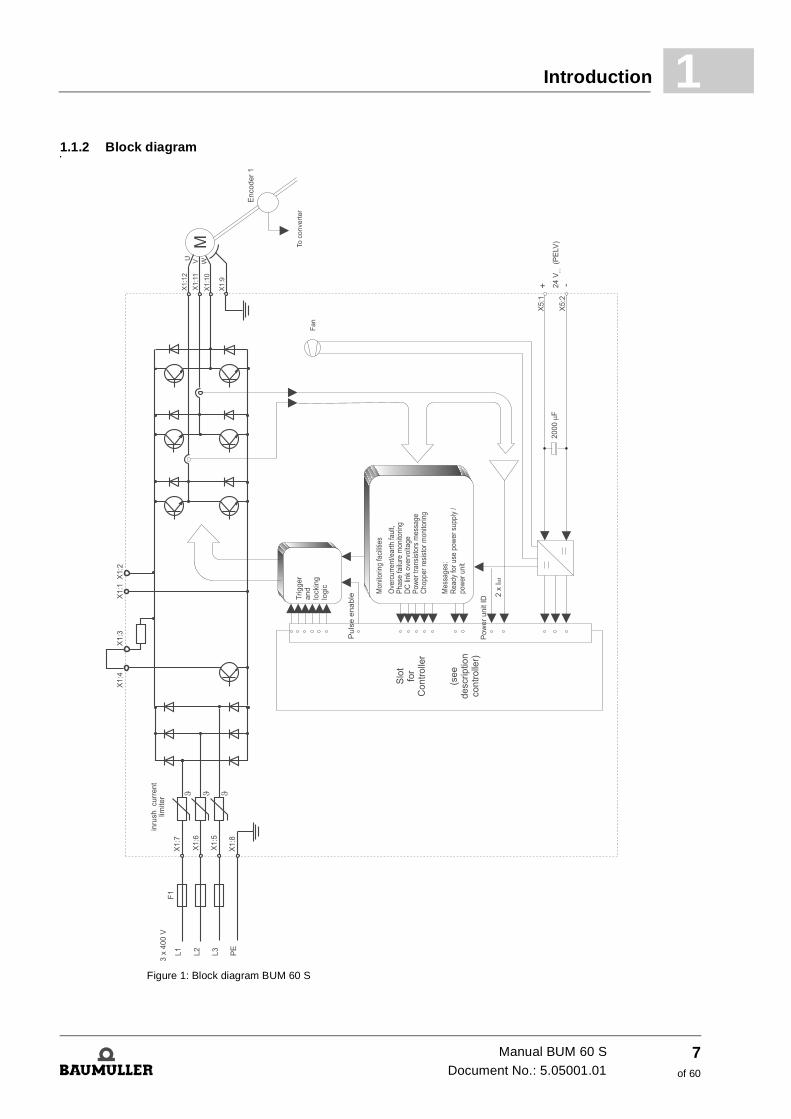
Introduction 1
1.1.2 Block diagramFigure 1: Block diagram BUM 60 S
Manual BUM 60 SDocument No.: 5.05001.01
7of 60
General information1.1
Manual BUM 60 S
Document No.: 5.05001.01 Baumüller Nürnberg GmbH
8of 60
2
2SAFETY INSTRUCTIONSPreliminary notes
During operation in the converter and in the motor discharging currents always occur against ground and can result in a premature response to a connected ELCB.
In case of a fault to frame or a ground fault a direct component in the ground leakage can occur, which complicates or avoids the enable of a higher-level ELCB.
The connection of power unit to the mains only with the use of the ELCB is forbidden (EN 50178/VDE 0160/4.98, paragraph 5.2.11 and 5.3.2.1)
The protection against touching of the units is achieved by the mounting of the converters into conventional control cabinets, which, regarding the protection type comply with the minimum requirements acc. to EN 50178/VDE 01604.98, paragraph 5.2.4.
Essential for personal protection are the safety precautions and safety instructions acc. to DIN/VDE.
In case there are missing protective ground connections at the unit or at the motor it must be reckoned on personal injury and/or considerable property damage.
General notes
This manual contains the required information for the specified use of the described products. This manual is intended for technically qualified personnel that has been specially trained and is completely familiar with all warnings and maintenance measures.
The devices are made according to the state-of-the-art technology and are fail-safe. It can be put into operation and function without problems if you ensure that the information in the manual is complied with.
WARNING
The following can occur, if you disregard this warning instruction:
f considerable damage to property f serious personal injury f death
When operating with this electrical unit, inevitably certain parts of this unit are under danger-ous voltage.
Make sure, that only qualified personnel, who is familiar with the safety- as well as with mount-ing-, operating- and maintenance instructions, works on this unit.
9of 60
Manual BUM 60 SDocument No.: 5.05001.01
Qualified personnel2.1
Safety notes
The definitions, which are used, have the following meaning in the terms of the manual and of the notes on the products:
2.1 Qualified personnel
In terms of notes corresponding to security in this manual or to the products itself, qualified per-sonnel are persons, who are familiar with the installation, mounting, commissioning and opera-tion of the product and who possess qualifications, which accord with their work :
f Education or instruction or to have the authorization to put into operation, ground and label circuits and devices according to the standards of safety engineering.
f Training or instruction due to the standards of the safety engineering in maintenance and use of appropriate safety equipment.
On the one hand the notes serve as your own security and on the other hand as a security against damage of the described products or of the connected devices.
DANGER
The following will occur, if you disregard this safety information:
f considerable damage to property f serious personal injury f death
WARNING
The following can occur, if you disregard this warning instruction:
f considerable damage to property f serious personal injury f death
NOTE
This note is a particularly important information.
Manual BUM 60 S
Document No.: 5.05001.01 Baumüller Nürnberg GmbH
10of 60
Safety instructions 2
2.2 Specified application2.3 Voltage check
At the routine test of these units a voltage check is executed acc. to EN 50178/VDE 0160/4.98, paragraph 9.4.5 by Baumüller Nürnberg GmbH.
Subsequent checks of unit with high voltages must be executed only by Baumüller Nürnberg GmbH.
WARNING
The following can occur, if you disregard this warning instruction:
f considerable damage to property f serious personal injury f death
The unit/system may only be used in the cases, which are described in the manual and may only be used with those devices and components of other manufacturers, which were recom-mended or permitted by Baumüller Nürnberg GmbH.
Arbitrary reconstructions and changes at the device are not permitted because of safety rea-sons.
The operator must immediately notify changes, which affect the security of the device/system.
WARNING
The following can occur, if you disregard this warning instruction:
f considerable damage to property f serious personal injury f death
If you want to check the complete control cabinet installation with high voltage, you must sep-arate all cable connections from the Baumüller units before checking.
Manual BUM 60 SDocument No.: 5.05001.01
11of 60
Voltage check2.3
Manual BUM 60 S
Document No.: 5.05001.01 Baumüller Nürnberg GmbH
12of 60
3
3PACKING AND TRANSPORTATIONThe devices are packed in the manufacturing company according to the order.
h Avoid strong transportation vibrations and severe hits, e.g. when setting down.
After unpacking and the check for completeness and the sound condition mounting can follow.
The packing is made of cardboard, corrugated cardboard and/or wood. They can be disposed according to the local disposal regulations.
h A transport damage is immediately to be notified.
DANGER
The following will occur, if you disregard this safety information:
f considerable damage to property f serious personal injury f death
If there is a transport damage at the unit, this may not be connected to the supply voltage with-out a correct voltage test.
13of 60
Manual BUM 60 SDocument No.: 5.05001.01

Manual BUM 60 S
Document No.: 5.05001.01 Baumüller Nürnberg GmbH
14of 60
4
4MOUNTINGWARNING
The following can occur, if you disregard this warning instruction:
f considerable damage to property f serious personal injury f death
The user carries the responsibility for the mounting of the described device according to the Safety instructions (e. g. EN, DIN, VDE) and other important national or local regulations, which concern conductor dimensioning and protection, grounding, disconnectors, overvolt-age protection a.s.o.
Cooling air intake and outtake must be unrestrictedly possible. There must be enough free space above and below the device, otherwise the device can overheat.
15of 60
Manual BUM 60 SDocument No.: 5.05001.01
Dimensions4.1
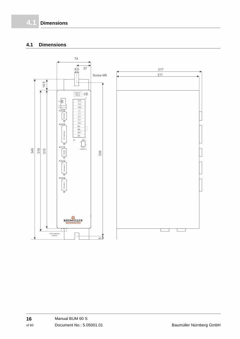
4.1 Dimensions
Manual BUM 60 S
Document No.: 5.05001.01 Baumüller Nürnberg GmbH
16of 60
Mounting 4
4.2 Mounting noteh The devices must be installed vertical into the control cabinet. If you have several devices these must be built in side by side.
h Ventilation must take place bottom-up.
h Unrestricted air supply must be provided.
h Free space above and below the devices must be at least 50 mm .Make sure, that there is enough cooling air and that there is air circulation!
h Cooling air temperature 50 mm below the device up to 40 °C. At higher temperatures (up to 55 °C) the power of the devices is reduced by 3% per °C.
h Do not group additional heat sources above and below the devices.
h Degree of pollution 3 and 4 according to EN 50178:4.98 paragraph 5.2.15.2 must be avoided. The devices can be mounted in isolated operating areas. (VDE 0558 part 1a, paragraph 5.4.3.2.1 and 5.4.3.2.2).
WARNING
The following can occur, if you disregard this warning instruction:
f considerable damage to property f serious personal injury f death
Incorrect lifting can lead to personal lifting or damage to property. Lift the unit only with suit-able equipment and/or with the help of qualified personnel.
WARNING
The following can occur, if you disregard this warning instruction:
f considerable damage to property f serious personal injury f death
The following cooling measures must be observed unconditionally. At non-observance the device can overheat.
DANGER
The following will occur, if you disregard this safety information:
f considerable damage to property f serious personal injury f death
Discharging time of components under voltage is > 1 min.
Manual BUM 60 SDocument No.: 5.05001.01
17of 60

Mounting note4.2
Manual BUM 60 S
Document No.: 5.05001.01 Baumüller Nürnberg GmbH
18of 60
5
5INSTALLATION5.1 Safety notes
WARNING
The following can occur, if you disregard this warning instruction:
f considerable damage to property f serious personal injury f death
This unit is under dangerous voltage and contains dangerous rotating machine parts (fan).
The user accounts for the mounting of the power units, the motor, the mains choke as well as the other devices according to the safety instructions (e. g. DIN, VDE) and all the other rele-vant national or local regulations concerning PCB dimensioning and protection, grounding, disconnectors, overvoltage protection a.s.o.
Essential for personal protection are the safety precautions and safety instructions acc. to DIN/VDE. If, at the device there are missing protective connections, at the commutating choke or at the motor it must be reckoned with personal damage, because there can be dangerous voltages on the surface.
During operation in the power unit and in the motor there are discharge currents to ground, which are discharged via the specified protective connection and can result in a release of a connected ELCB.
In case of a fault to frame or a ground fault a direct component in the ground leakage can oc-cur, which complicates or avoids the enable of a higher-level ELCB. The protective conductor connection must be executed to DIN EN 60204/VDE 0113 part 1/1997; paragraph 8.2.2 with consideration to EN 50178 / VDE 0160/ 4.98, paragraphs 5.3.2.1 and 8.3.4.4.
If there is an error then the drive is changed to zero-current, after that the motor coasts down non-braked. This must especially be considered at travel- and lift drives.
Before activating the drive the function of all higher-levelled safety devices must be checked thoroughly, in order to avoid personal danger.
19of 60
Manual BUM 60 SDocument No.: 5.05001.01
Safety notes5.1
WARNING
The following can occur, if you disregard this warning instruction:
f severe injury f death
The danger is: electricity. Parts, which are under tension are perilous.
Assure, that the parts, which must be mounted (e. g. mains cables) and the mounting range are off-circuit during the entire mounting of the device.
WARNING
The following can occur, if you disregard this warning instruction:
f considerable damage to property f serious personal injury f death
Incorrect behavior of the drive During the initial operation an incorrect or uncontrolled movement of the powered machine elements can occur. Therefore you must approach with reasonable caution.
Protection against accidental contact according to §4 para. 4 VBG 4 Protection against direct contact, cover all measures against danger, which consults from the contact to active parts of electric equipment.
Control cabinets must have emergency stops, where all voltages. which can cause hazards, can be switched off. This does not include equipment, where a new hazard occurs, when it is switched off. The tripping device for the emergency stops must be placed in such a manner, that it can be reached quickly, if there is an hazardous situation. In case there are obviously dangerous operations to be executed, then the presence of a further person is necessary.
The operator must assure that only authorized persons are working at the machine.
The operator is bound to immediately notify, if there are changes on the machine, which could have influence on the security.
Before the demounting of safety equipment during commissioning, repair and maintenance the machine is to be shutdown according to the regulations. Immediately after completion of commissioning-, repair- and maintenance working, the remounting of the safety equipment must be done and the safety equipment must be checked.
Manual BUM 60 S
Document No.: 5.05001.01 Baumüller Nürnberg GmbH
20of 60
Installation 5
5.2 EMC instructionsGeneral information about converter
In Baumüller Nürnberg GmbH converters IGBTs are used. Due to the quick switch of the IGBTs the power loss in the converter is minimized. Therewith the size of the power units was reduced. However the quick switching of the IGBTs can lead to electromagnetic interferences, which can influence other parts.
Interferences can be caused by:
f Capacitive leakage current. The cause is the high voltage gradients at the switching of bipolar transistors and IGBTs.
f High currents and current gradients in the motor cables. The bonded interference energy in the magnetic field reaches frequencies of a few hertz up to about 30 MHz. Due to the high voltage gradients additionally electromagnetic fields with frequencies up to 600 MHz occur.
f High clock-pulse rates and quick logic switchings (electromagnetic field of 16 MHz to 1 GHz).
f Reaction on system and harmonics. The cause are commutation procedures and not sinuso-idal mains loadings especially at line-commutated converters (100Hz... 20 kHz).
EMC regulation (EMVG)
This converter accords to § 6 para. 9 of the EMVG dated September 18, 1998:
„Devices, systems and parts in terms of paragraph 3, which exclusively are manufactured and are determined as subcontracting parts or spare parts for the subsequent processing by com-petent companies or persons in the field of electromagnetic compatibility, must not fulfill the pro-tection requirements as well as the requirements of § 4 para. No. 1 to 3 and 5 comply with.“
Thereby it is allowed for, that in order to comply with the EMC it is decisive, how the single parts and components are mounted in the control cabinet.
Measures for EMC-assurance
In order to minimize electromagnetic interferences, certain preconditions must be complied with at cabling, grounding, screening and at mounting of filters. The notes of the following page will help you, to configure the installation according to the latest EMC knowledge.
Cabling
f For suppression of the interfering radiation outside the converter you basically must screen all connected cables. If the control cabinet has a sufficiently high degree of screening atten-uation (see limit values of the radio interference emission according to EMVG for your instal-lation) and if the EMC compatibility in the interior space is guaranteed (you may assume that, if all configuration notes have been adhered to), the control cables also may be mounted un-screened.
Manual BUM 60 SDocument No.: 5.05001.01
21of 60
EMC instructions5.2
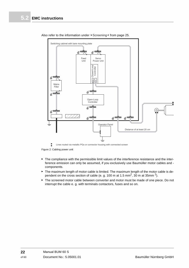
Also refer to the information under ZScreening– from page 25.
Figure 2: Cabling power unit
f The compliance with the permissible limit values of the interference resistance and the inter-ference emission can only be assumed, if you exclusively use Baumüller motor cables and -components.
f The maximum length of motor cable is limited. The maximum length of the motor cable is de-pendent on the cross section of cable (e. g. 100 m at 1.5 mm2, 30 m at 35mm 2).
f The screened motor cable between converter and motor must be made of one piece. Do not interrupt the cable e. g. with terminals contactors, fuses and so on.
Manual BUM 60 S
Document No.: 5.05001.01 Baumüller Nürnberg GmbH
22of 60
Installation 5
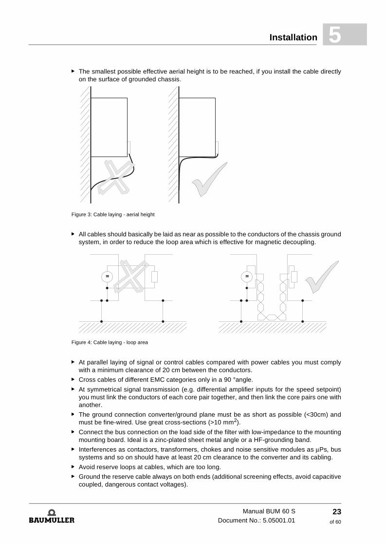
f The smallest possible effective aerial height is to be reached, if you install the cable directlyon the surface of grounded chassis.
Figure 3: Cable laying - aerial height
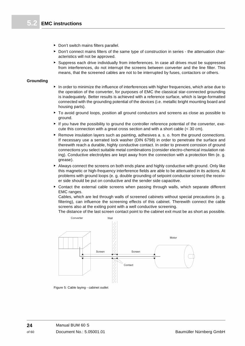
f All cables should basically be laid as near as possible to the conductors of the chassis ground system, in order to reduce the loop area which is effective for magnetic decoupling.
Figure 4: Cable laying - loop area
f At parallel laying of signal or control cables compared with power cables you must comply with a minimum clearance of 20 cm between the conductors.
f Cross cables of different EMC categories only in a 90 °angle.
f At symmetrical signal transmission (e.g. differential amplifier inputs for the speed setpoint) you must link the conductors of each core pair together, and then link the core pairs one with another.
f The ground connection converter/ground plane must be as short as possible (<30cm) and must be fine-wired. Use great cross-sections (>10 mm2).
f Connect the bus connection on the load side of the filter with low-impedance to the mounting mounting board. Ideal is a zinc-plated sheet metal angle or a HF-grounding band.
f Interferences as contactors, transformers, chokes and noise sensitive modules as μPs, bus systems and so on should have at least 20 cm clearance to the converter and its cabling.
f Avoid reserve loops at cables, which are too long.
f Ground the reserve cable always on both ends (additional screening effects, avoid capacitive coupled, dangerous contact voltages).
Manual BUM 60 SDocument No.: 5.05001.01
23of 60
EMC instructions5.2
f Don’t switch mains filters parallel.
f Don’t connect mains filters of the same type of construction in series - the attenuation char-acteristics will not be approved.
f Suppress each drive individually from interferences. In case all drives must be suppressed from interferences, do not interrupt the screens between converter and the line filter. This means, that the screened cables are not to be interrupted by fuses, contactors or others.
Grounding
f In order to minimize the influence of interferences with higher frequencies, which arise due to the operation of the converter, for purposes of EMC the classical star-connected grounding is inadequately. Better results is achieved with a reference surface, which is large-formatted connected with the grounding potential of the devices (i.e. metallic bright mounting board and housing parts).
f To avoid ground loops, position all ground conductors and screens as close as possible to ground.
f If you have the possibility to ground the controller reference potential of the converter, exe-cute this connection with a great cross section and with a short cable (< 30 cm).
f Remove insulation layers such as painting, adhesives a. s. o. from the ground connections. If necessary use a serrated lock washer (DIN 6798) in order to penetrate the surface and therewith reach a durable, highly conductive contact. In order to prevent corrosion of ground connections you select suitable metal combinations (consider electro-chemical insulation rat-ing). Conductive electrolytes are kept away from the connection with a protection film (e. g. grease).
f Always connect the screens on both ends plane and highly conductive with ground. Only like this magnetic or high-frequency interference fields are able to be attenuated in its actions. At problems with ground loops (e. g. double grounding of setpoint conductor screen) the receiv-er side should be put on conductive and the sender side capacitive.
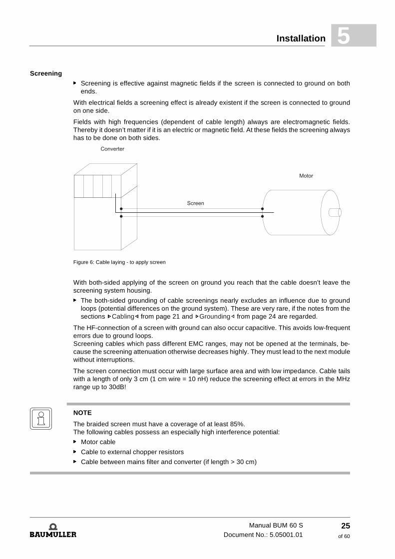
f Contact the external cable screens when passing through walls, which separate different EMC ranges. Cables, which are led through walls of screened cabinets without special precautions (e. g. filtering), can influence the screening effects of this cabinet. Therewith connect the cable screens also at the exiting point with a well conductive screening. The distance of the last screen contact point to the cabinet exit must be as short as possible.
Figure 5: Cable laying - cabinet outlet
Manual BUM 60 S
Document No.: 5.05001.01 Baumüller Nürnberg GmbH
24of 60
Installation 5
Screeningf Screening is effective against magnetic fields if the screen is connected to ground on both ends.
With electrical fields a screening effect is already existent if the screen is connected to ground on one side.
Fields with high frequencies (dependent of cable length) always are electromagnetic fields. Thereby it doesn’t matter if it is an electric or magnetic field. At these fields the screening always has to be done on both sides.
Figure 6: Cable laying - to apply screen
With both-sided applying of the screen on ground you reach that the cable doesn’t leave the screening system housing.
f The both-sided grounding of cable screenings nearly excludes an influence due to ground loops (potential differences on the ground system). These are very rare, if the notes from the sections ZCabling– from page 21 and ZGrounding– from page 24 are regarded.
The HF-connection of a screen with ground can also occur capacitive. This avoids low-frequent errors due to ground loops. Screening cables which pass different EMC ranges, may not be opened at the terminals, be-cause the screening attenuation otherwise decreases highly. They must lead to the next module without interruptions.
The screen connection must occur with large surface area and with low impedance. Cable tails with a length of only 3 cm (1 cm wire = 10 nH) reduce the screening effect at errors in the MHz range up to 30dB!
NOTE
The braided screen must have a coverage of at least 85%. The following cables possess an especially high interference potential:
f Motor cable
f Cable to external chopper resistors
f Cable between mains filter and converter (if length > 30 cm)
Manual BUM 60 SDocument No.: 5.05001.01
25of 60
EMC instructions5.2
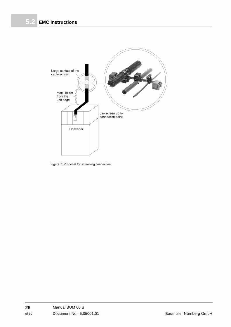
Figure 7: Proposal for screening connection
Manual BUM 60 S
Document No.: 5.05001.01 Baumüller Nürnberg GmbH
26of 60
Installation 5
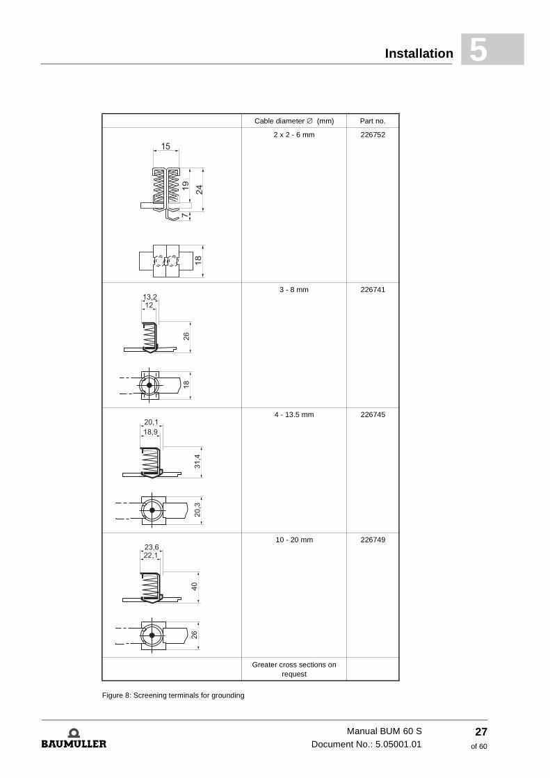
Figure 8: Screening terminals for grounding
Cable diameter ∅ (mm) Part no.
2 x 2 - 6 mm 226752
3 - 8 mm 226741
4 - 13.5 mm 226745
10 - 20 mm 226749
Greater cross sections on request
Manual BUM 60 SDocument No.: 5.05001.01
27of 60
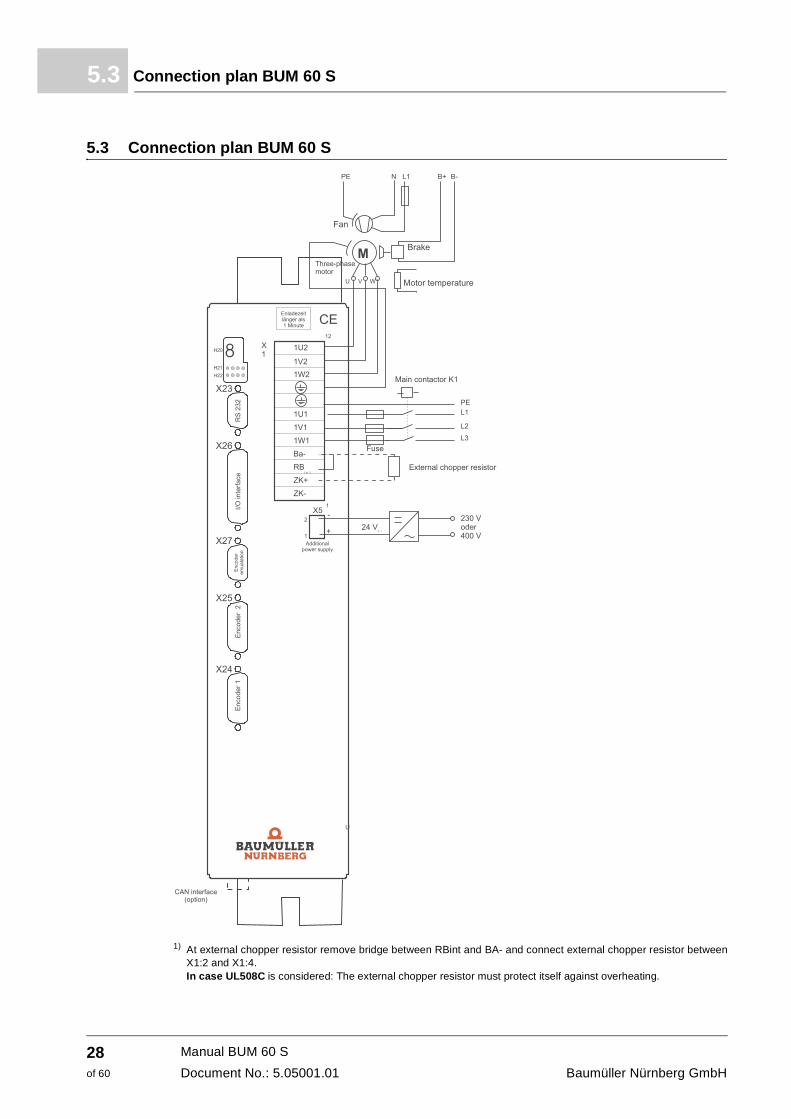
Connection plan BUM 60 S5.3
5.3 Connection plan BUM 60 S
1) At external chopper resistor remove bridge between RBint and BA- and connect external chopper resistor between X1:2 and X1:4. In case UL508C is considered: The external chopper resistor must protect itself against overheating.
Manual BUM 60 S
Document No.: 5.05001.01 Baumüller Nürnberg GmbH
28of 60
Installation 5
5.4 Connection instructionsController module
See separate controller description
K1 Main contactor, with auxiliary contact for controller release
DANGER
The following will occur, if you disregard this safety information:
f considerable damage to property f serious personal injury f death
Controller release at the controller must be made after the complete loading of DC-link capac-itors, this is, at the earliest, 1 s after switching on the main contactor
F Cable protection according to VDE 0100, fuse delayed, 2...2,3-time rated current or motor protector, matched to the power requirement of the drive and of the starting peak current.
1U2, 1V2, 1W2, S
Motor connections. Cross section according to VDE 0113/0298. Use screened cables. Laying of the cables see ZEMC instructions– from page 21. Cross sections: 1.5 mm2 to 14 A, 2.5 mm2 to 19 A, 4 mm2 to 25 A, 6 mm2 via 25 A motor rated current. Consider the connections in the terminal box.
1U1, 1V1, 1W1, S
Connection to mains. Cross section according to VDE 0113/0298. Laying of the cables see ZEMC instructions– from page 21.
NOTE
At one-phase supply one connection not required.
RBint Connection internal chopper resistor
Ba- Connection chopper transistor; Connection external chopper resistor between DC+ and BA-. In case UL508C is considered: The external chopper resistor must protect itself against over-heating.
Manual BUM 60 SDocument No.: 5.05001.01
29of 60
Connection instructions5.4
DANGER
The following will occur, if you disregard this safety information:
f considerable damage to property f serious personal injury f death
If you are using an external chopper resistor the bridge between RBint and BA- must be re-moved. Otherwise the chopper transistor will be overloaded and destroyed.
DC+, DC- Connection of DC-link voltageConnections of DC-link voltage. Discharge of the DC link capacitors lasts at least 1 minute. Quick discharge of the DC-link via resistor, if necessary. Connection of an external chopper resistor between DC+ and BA-. In case UL508C is considered: The external chopper resistor must protect itself against over-heating.
DANGER
The following will occur, if you disregard this safety information:
f considerable damage to property f serious personal injury f death
A parallel switching of several devices via the DC-link connection is not permitted. Due to this the inrush-current limiting is overloaded and destroyed.
Manual BUM 60 S
Document No.: 5.05001.01 Baumüller Nürnberg GmbH
30of 60
Installation 5
5.5 Connector- and terminal assignment5.5.1 Power connections
1U1, 1V1, 1W1, S (connections: maximum 4 mm2)
1U1, 1V1, 1W1
Input voltage of device
NOTE
At one-phase supply one connection not required.
S Control cabinet-ground
1U2, 1V2, 1W2, S (connections: maximum 4 mm2)
1U2, 1V2, 1W2
Motor connections
S Ground connection motor
DC+, DC- (connections: maximum 4 mm2)
Connection of DC-link voltageConnections of DC-link voltage. Discharge of the DC link capacitors lasts at least 1 minute. Quick discharge of the DC-link via resistor, if necessary. Connection of an external chopper resistor between DC+ and BA-.
RBint, Ba-
At internal chopper resistor bridgeAt external chopper resistor see ZBlock diagram– from page 7 and ZConnection plan BUM 60 S– on page 28.In case UL508C is considered: The external chopper resistor must protect itself against over-heating.
Manual BUM 60 SDocument No.: 5.05001.01
31of 60
Accessories5.6
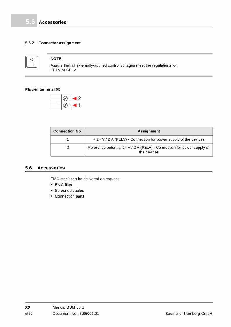
5.5.2 Connector assignment
Plug-in terminal X5
5.6 Accessories
EMC-stack can be delivered on request:
f EMC-filter
f Screened cables
f Connection parts
NOTE
Assure that all externally-applied control voltages meet the regulations for PELV or SELV.
Connection No. Assignment
1 + 24 V / 2 A (PELV) - Connection for power supply of the devices
2 Reference potential 24 V / 2 A (PELV) - Connection for power supply of the devices
Manual BUM 60 S
Document No.: 5.05001.01 Baumüller Nürnberg GmbH
32of 60
6
6COMMISSIONING6.1 Safety notes
WARNING
The following can occur, if you disregard this warning instruction:
f considerable damage to property f serious personal injury f death
This unit is under dangerous voltage and contains dangerous rotating machine parts (fan). Not meeting with safety- and warning notes can lead to death, severe personal injury or dam-ages to property.
The user is in charge of the mounting of the power units, the motor, the mains filter as well as of the other devices according to safety regulations (e. g. DIN, VDE) and the other relevant national and local regulations, which regard conductor dimensioning and grounding, discon-necting switches, overcurrent protection a.s.o.
Essential for personal protection are the safety precautions and safety instructions acc. to DIN/VDE. If the protective conductor is not connected to the existing protective conductor connections of device and motor, it must be anticipated that personal injury occurs, be-cause there can be dangerous voltages on the surface.
The power connections of power unit are non-isolated!
Even if the main contactor is falling the parts of the power unit are under dangerous voltages.
During operation in the power unit and in the motor there are discharge currents to ground, which are discharged via the specified protective connection and can result in a release of a connected ELCB.
In case of a fault to frame or a ground fault a direct component in the ground leakage can oc-cur, which complicates or avoids the enable of a higher-level ELCB. The protective ground connection must be executed according to DIN EN 60204 / VDE 0113 part 1 / 1997; paragraph 8.2.2 considering EN 50178 / VDE 0160/ 4.98, paragraphs 5.3.2.1 and 8.3.4.4.
Incorrect behavior of the drive During the initial operation an incorrect or uncontrolled movement of the powered machine elements can occur. Therefore you must approach with reasonable caution.
33of 60
Manual BUM 60 SDocument No.: 5.05001.01
Safety notes6.1
WARNING
The following can occur, if you disregard this warning instruction:
f considerable damage to property f serious personal injury f death
Before activating the drive the function of all higher-levelled safety devices must be checked thoroughly, in order to avoid personal danger.
Special caution is necessary at direct or indirect contact of drive shaft (of hand). This is only permitted at standstill of what and off-circuit power unit. If there are uncovered machine parts, these must be covered at operation (shafts, fans, or similar).
Contact protection according to §4 para. 4 VBG 4 Protection against direct contact contains all measures against dangers, which occur at the contact of voltage-controlled parts of electric equipment. The voltage-controlled parts must be protected against direct contact by insulation, type of construction, assignment or fixed-mounted equipment. This concerns the usual covers, guard and procedures, which guarantee, that persons cannot touch the parts, which are under volt-age.
Control cabinets must have emergency stops, where all voltages. which can cause hazards, can be switched off. This does not include equipment, where a new hazard occurs, when it is switched off. The release of the emergency stop must be attached, so that, if there is danger, it can be reached quickly. In case there are obviously dangerous operations to be executed, then the presence of a further person is necessary.
The operator must assure that only authorized persons are working at the machine.
Subsequent checks of unit with high voltages must be made only by Baumüller Nürnberg Gm-bH. If you want to check complete control cabinet installation with high voltage, you must sep-arate all cable connections from the Baumüller units before checking.
If there is an error then the drive is changed to zero-current, after that the motor coasts down non-braked. This must especially be considered at travel- and lift drives.
The operator is bound to immediately notify, if there are changes on the machine, which could have influence on the security.
Before demounting safety equipment for commissioning, repair or maintenance set the ma-chine in exact accordance with the instructions out of operation. Directly after completion of commissioning-, repair- and maintenance works, the re-mounting of the safety equipment must be made and this must be checked.
This is not a complete listing of all required measures for the safe operation of the power unit. Should you require further information or if there are specifically problems, contact Baumüller Nürnberg GmbH or a sales branch office. Please regard to the warning notes in chapter ZSafety instructions– from page 9.
Units with electrostatic endangered components or modules are tagged at a visible position with this label.
Manual BUM 60 S
Document No.: 5.05001.01 Baumüller Nürnberg GmbH
34of 60
Commissioning 6
6.2 Operation
The operation of the device is made via the controller (see according controller description).
The saving of messages in the infeed converter/motor-sided inverter can reset with a reset sig-nal from the controller.
6.3 Messages and warnings
6.3.1 Monitoring of infeed converter
For the monitoring functioning there must be a 24V-auxiliary supply.
Chopper resistor monitoring
The chopper resistor monitoring avoids an inadmissible overload of the internal chopper resistor (ED < 3 %).
Mains-/phase failure monitoring (option)
The phase failure monitoring recognizes a one- and a three-phase failure of the supply voltage and avoids an internal ready-to-operate.
NOTE
Before touching the modules the operator must discharge himself electrostatic, in order pro-tect electronic parts of high voltages, which can occur at electrostatic charge. This can hap-pen, by touching a conductive and grounded part directly before.
NOTE
If there is a 24V-auxiliary voltage at X5 the message can only be reset 2 s after a re-switch in of the supply voltage at X1 via RESET. For switch on under normal operating conditions a simultaneously switching of the supply voltages at X1 and X5 is recommended.
Manual BUM 60 SDocument No.: 5.05001.01
35of 60
Messages and warnings6.3
6.3.2 Monitoring motor-sided inverter
The following monitoring is present:
f Overcurrent in the motor cables
f Ground fault current
f DC-link overvoltage
f Power transistors
f Overtemperature
Overcurrent message
The motor current in the motor phases is monitored and an exceeding of a phase current by 30 % of the permissible peak current generates an overcurrent message. This message is saved and causes a pulse inhibit.
The overcurrent message can be reset by the reset of the controller. Display and reset of message see description of the controller.
Ground current monitoring
The ground current of the motor-sided inverter and therewith of the motor phases is monitored at two phases, in order to recognize a motor grounding. A ground current error message is gen-erated, if the error current exceeds 10 % of the permissible peak current of the power unit. By the monitoring of two phases the device is conditionally ground fault protected.
The ground current monitoring can be reset by a reset of the controller. Display and reset of message see description of the controller.
DC-link monitoring
The level of the DC-link voltage is monitored in the inverter. If the DC-link voltage reaches a val-ue, which is critical for the power unit, a message is generated.
The DC-link monitoring can be reset by a reset of the controller. Display and reset of message see description of the controller.
Monitoring of power transistors
The junction temperature is monitored. A message is generated, if a junction temperature of 110 °C is exceeded.
This message can be reset by a reset of the controller. Display and reset of message see description of the controller.
NOTE
The overcurrent message is regarded as a protection, the limit of the permissible peak current of the motor phase current is guaranteed by the control.
NOTE
The DC-link voltage can increase until switch-off takes place, if the drive brakes and if there is no or too little chopper circuit with a too little chopper power at the DC-link circuit.
Manual BUM 60 S
Document No.: 5.05001.01 Baumüller Nürnberg GmbH
36of 60
Commissioning 6
Monitoring of the heatsink temperatureThe power unit has no own temperature monitoring, because the temperature of the heatsink is no time-critical factor. On the heatsink there is a linear temperature sensor, whose measured value is transmitted to the controller. The controller therewith takes over the temperature monitoring (see description of the controller).
6.3.3 Error messages
� Function module supply (error identification 01xx)
NOTE
When using the BUM 60 S together with the V-controller then only the error messages below are valid.
The accordant error messages in the documentation for the V-controller are invalid!
Error identifi-cation
Error text Meaning Error reaction Troubleshooting
0110hex
Error Supply unit
The signal „Ready-to-operate“ of the supply unit is missingPossible cause:Error 0203hex
Error 0204hex
Error 0207hex
Immediate pulse inhibit
Check mains voltage at the supply unit.Reset error memory in the supply unit (see manual supply unit)Other trouble shooting: see error 0203hex, 0204hex as well as 0207hex
Manual BUM 60 SDocument No.: 5.05001.01
37of 60
Messages and warnings6.3
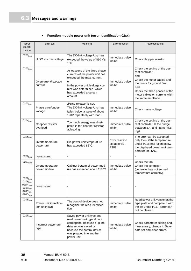
� Function module power unit (error identification 02xx)
Error identifi-cation
Error text Meaning Error reaction Troubleshooting
0201hex
U DC link overvoltageThe DC-link voltage UDC has exceeded the value of 810 V± 1 %
Immediate pulse inhibit
Check chopper resistor
0202hex
Overcurrent/leakage current
At least one of the three phase currents of the power unit has exceeded the max. current. orIn the power unit leakage cur-rent was determined, which has exceeded a certain amount.
Immediate pulse inhibit
Check the setting of the cur-rent controller. andCheck the motor cables and the motor for ground fault. andCheck the three phases of the motor cables on currents with the same amplitude.
0203hex
Phase error/under-voltage
„Pulse release“ is set.The DC-link voltage UDC has fallen below a value of about 190V repeatedly with load.
Immediate pulse inhibit
Check mains voltage.
0204hex
Chopper resistor overload
Too much energy was dissi-pated in the chopper resistor at braking.
Immediate pulse inhibit
Check the setting of the cur-rent controller. Is the bridge between BA- and RBint miss-ing?
0205hex
Overtemperature power unit
Die power unit temperature has exceeded 85°C.
Error reaction settable via P189
The error can be accepted only then, if the temperature under P118 has fallen below the displayed power unit tem-perature of 85°C.
0206hex nonexistent - - -
0207hex
Overtemperature power module
Cabinet bottom of power mod-ule has exceeded about 110°C
Immediate pulse inhibit
Check the fanCheck the controller (controller has not sensed temperature correctly)
0208hex0209hex020A hex020Bhex020Chex020Dhex
nonexistent - - -
020Ehex
Power unit identifica-tion unknown
The control device does not recognize the read identifica-tion
Immediate pulse inhibit
Read power unit version at the type plate and compare it with the list under P117. Error can-not be cleared.
020Fhex
Incorrect power unit type
Saved power unit type and read power unit type do not correspond, because e. g. no data set was saved or because the control device was plugged into another power unit.
Immediate pulse inhibit
Check parameter setting and, if necessary, change it. Save data set and clear errors.
Manual BUM 60 S
Document No.: 5.05001.01 Baumüller Nürnberg GmbH
38of 60
Commissioning 6
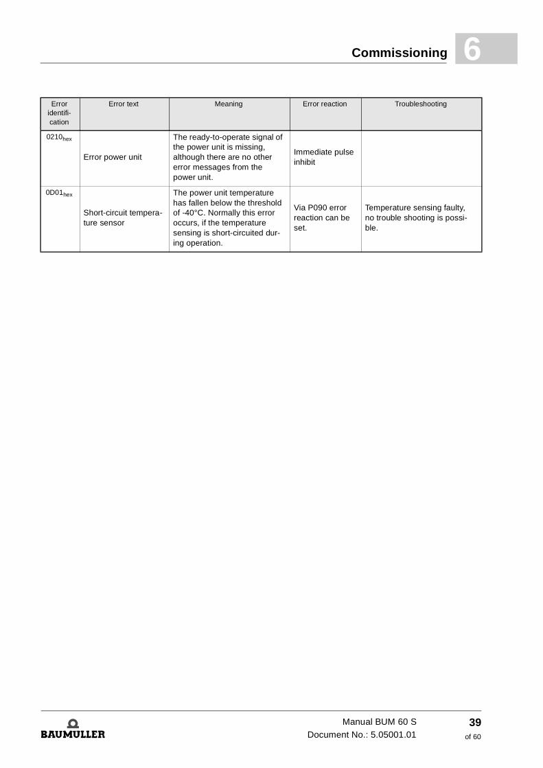
0210hex
Error power unit
The ready-to-operate signal of the power unit is missing, although there are no other error messages from the power unit.
Immediate pulse inhibit
0D01hex
Short-circuit tempera-ture sensor
The power unit temperature has fallen below the threshold of -40°C. Normally this error occurs, if the temperature sensing is short-circuited dur-ing operation.
Via P090 error reaction can be set.
Temperature sensing faulty, no trouble shooting is possi-ble.
Error identifi-cation
Error text Meaning Error reaction Troubleshooting
Manual BUM 60 SDocument No.: 5.05001.01
39of 60
Messages and warnings6.3
Manual BUM 60 S
Document No.: 5.05001.01 Baumüller Nürnberg GmbH
40of 60
7
7MAINTENANCE7.1 Maintenance notes
The devices, which are supplied are maintenance-free.
Prohibition of arbitrarily reconstructions
Arbitrarily reconstructions or changes of any kind at the drive are prohibited due to safety rea-sons.
WARNING
The following can occur, if you disregard this warning instruction:
f considerable damage to property f serious personal injury f death
This unit is under dangerous voltage and contains dangerous rotating machine parts (fan). The noncompliance with the safety- and warning notes can cause to death, severe bodily in-jury or to damages to property.
Maintenance- and repair works must be made only in an off-circuit status of the device.
Begin with works at the unit, if you have assured, that there is neither potential nor voltage (residual load) present.
In order to commission or repair, set the machine in exact accordance with the instructions out of operation before beginning with the demounting of safety devices. Directly after com-pletion of commissioning-, repair- and maintenance works the mounting of the safety devices must be made.
After each intervention in the drive (it does not matter if in the motor, actual value sensing or in the converter), the user of the machine must approve the machine and document this chro-nological in the machine protocol (maintenance notebook or similar). At non-compliance legal consequences will be initiated against the user.
41of 60
Manual BUM 60 SDocument No.: 5.05001.01
Storage conditions7.2
7.2 Storage conditions
If you keep to the environmental conditions during the entire period of storage, you can assume, that the device will not be damaged.
7.3 Recommissioning
Execute commissioning as with a new device
WARNING
The following can occur, if you disregard this warning instruction:
f considerable damage to property f serious personal injury f death
From a six month storage period on, the capacitors are destroyed during commissioning, if they are not reformed beforehand.
Reform the capacitors by supplying the device ready-to-operate for at least 48 hours with sup-ply voltage, but do not transmit a pulse enable.
WARNING
The following can occur, if you disregard this warning instruction:
f considerable damage to property f serious personal injury f death
From a six month storage period on, the capacitors are destroyed during commissioning, if they are not reformed beforehand.
Reform the capacitors by supplying the device ready-to-operate for at least 48 hours with supply voltage, but do not transmit a pulse enable.
Manual BUM 60 S
Document No.: 5.05001.01 Baumüller Nürnberg GmbH
42of 60
Maintenance 7
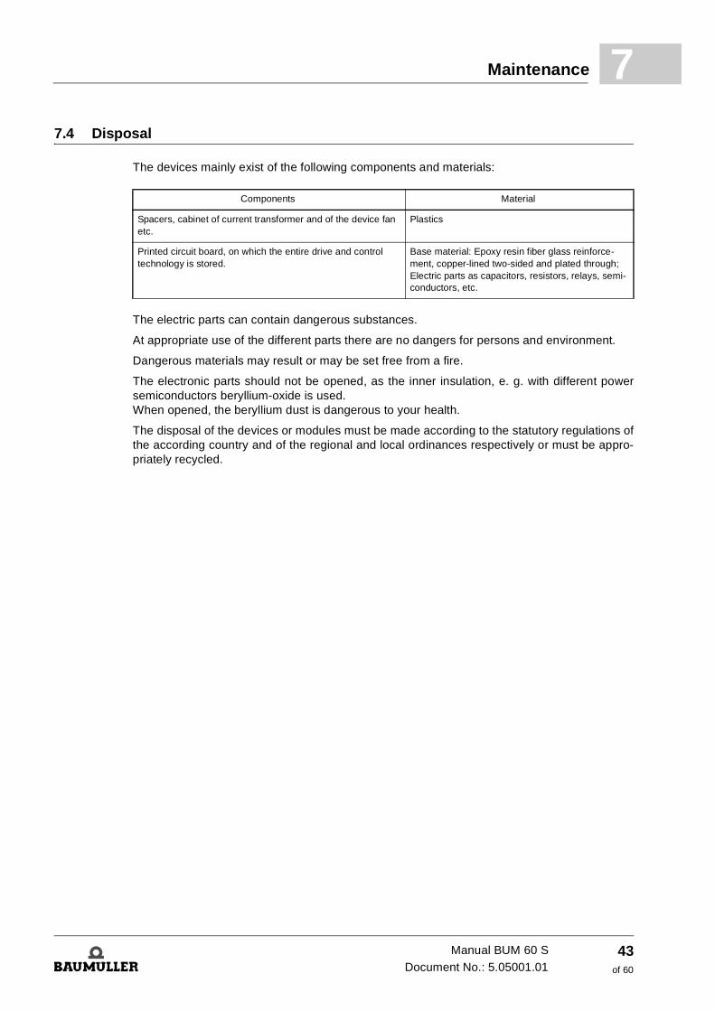
7.4 DisposalThe devices mainly exist of the following components and materials:
The electric parts can contain dangerous substances.
At appropriate use of the different parts there are no dangers for persons and environment.
Dangerous materials may result or may be set free from a fire.
The electronic parts should not be opened, as the inner insulation, e. g. with different power semiconductors beryllium-oxide is used. When opened, the beryllium dust is dangerous to your health.
The disposal of the devices or modules must be made according to the statutory regulations of the according country and of the regional and local ordinances respectively or must be appro-priately recycled.
Components Material
Spacers, cabinet of current transformer and of the device fan etc.
Plastics
Printed circuit board, on which the entire drive and control technology is stored.
Base material: Epoxy resin fiber glass reinforce-ment, copper-lined two-sided and plated through; Electric parts as capacitors, resistors, relays, semi-conductors, etc.
Manual BUM 60 SDocument No.: 5.05001.01
43of 60
Disposal7.4
Manual BUM 60 S
Document No.: 5.05001.01 Baumüller Nürnberg GmbH
44of 60
A
APPENDIX A - ABBREVIATIONSAC Alternating current
AM Asynchronous motor
a.m.s.l. above mean sea level
BB Ready for use
BUC Baumüller Converter Feed/Feed Back Unit
BUG Baumüller Converter Basic Feed Unit
BUM Baumüller Single Power Unit
BUS Baumüller Power Module
DC Direct current
DIN Deutsches Institut für Normung e.V. (German Standardization Authori-ty)
EMC Electromagnetic compatibility
EN European Standard
FBS BEDAS missing
FLG Fault in position encoder signal
FPH Missing phase
FTO Fault in tachometer generator sig-nal
HS Main contactor
MC Main contactor
IPM Intelligent power module
IZK Overcurrent in intermediate circuit
NMX Maximum RPM exceeded
PE Protective earth
PELV Protective extra-low voltage
RS Controller disable
SELV Safe extra-low voltage
SGR Current limit reached
SM Synchronous motor
TBA Overtemperature of ballast resis-tor
TKK Overtemperature of heat sink
TMO Overtemperature of motor
UVS Supply voltage too low
UZK DC link voltage
ZK DC link
45of 60
Manual BUM 60 SDocument No.: 5.05001.01

A
Manual BUM 60 S
Document No.: 5.05001.01 Baumüller Nürnberg GmbH
46of 60
B
APPENDIX B - TECHNICAL DATAB.1 Required environmental conditions
1) The environmental temperature is determined as follows:
2) Load values subject to the site altitude at site altitude > 1000 m
Operational ambient temperature range TB 1) 0 ... 40 °C
(with derating (3 % / °C) to 55 °C)
Cooling air temperature range TK 0 ... 40 °C(with derating (3 % / °C) to 55 °C)
Reducing of nominal current output (TK = 45...55°C) 3 % / °C
Max. mounting height at load rating 2) Absolute altitude
Relative humidity 15 % ... 85 % not moisture condensated
Storage temperature range -30 °C ... +70 °C
� Several measuring points, which cover the entire drawn in range, determine according to the adjoining drawing spaced at intervals of 10 cm.
� Measure temperature at these measuring points.
The greatest value is the ambient temperature
47of 60
Manual BUM 60 SDocument No.: 5.05001.01
Mechanical dataB.2
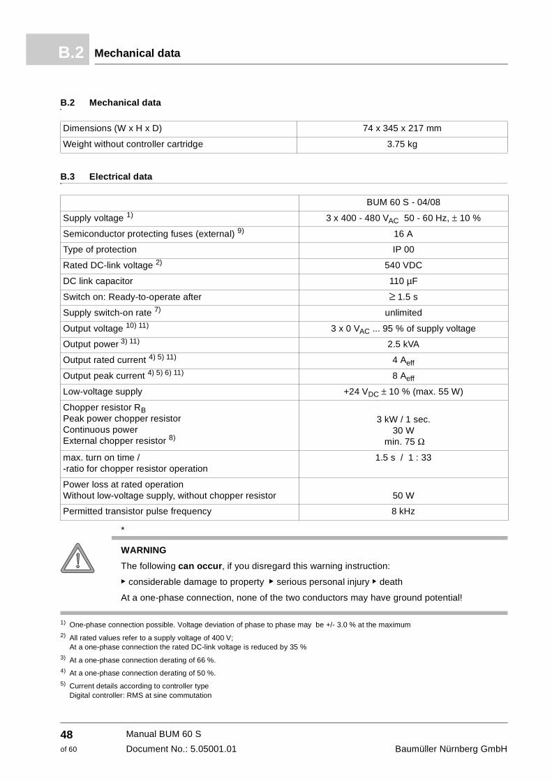
B.2 Mechanical data
B.3 Electrical data
*
1) One-phase connection possible. Voltage deviation of phase to phase may be +/- 3.0 % at the maximum 2) All rated values refer to a supply voltage of 400 V;
At a one-phase connection the rated DC-link voltage is reduced by 35 %3) At a one-phase connection derating of 66 %.4) At a one-phase connection derating of 50 %.5) Current details according to controller type
Digital controller: RMS at sine commutation
Dimensions (W x H x D) 74 x 345 x 217 mm
Weight without controller cartridge 3.75 kg
BUM 60 S - 04/08
Supply voltage 1) 3 x 400 - 480 VAC 50 - 60 Hz, ± 10 %
Semiconductor protecting fuses (external) 9) 16 A
Type of protection IP 00
Rated DC-link voltage 2) 540 VDC
DC link capacitor 110 µF
Switch on: Ready-to-operate after ≥ 1.5 s
Supply switch-on rate 7) unlimited
Output voltage 10) 11) 3 x 0 VAC ... 95 % of supply voltage
Output power 3) 11) 2.5 kVA
Output rated current 4) 5) 11) 4 Aeff
Output peak current 4) 5) 6) 11) 8 Aeff
Low-voltage supply +24 VDC ± 10 % (max. 55 W)
Chopper resistor RBPeak power chopper resistor Continuous power External chopper resistor 8)
3 kW / 1 sec.30 W
min. 75 Ω
max. turn on time / -ratio for chopper resistor operation
1.5 s / 1 : 33
Power loss at rated operation Without low-voltage supply, without chopper resistor 50 W
Permitted transistor pulse frequency 8 kHz
WARNING
The following can occur, if you disregard this warning instruction:
f considerable damage to property f serious personal injury f death
At a one-phase connection, none of the two conductors may have ground potential!
Manual BUM 60 S
Document No.: 5.05001.01 Baumüller Nürnberg GmbH
48of 60
Technical data B
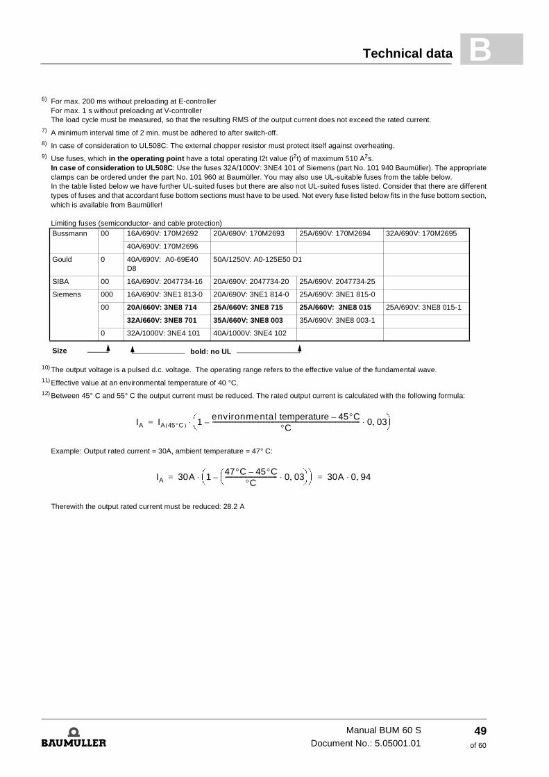
6) For max. 200 ms without preloading at E-controllerFor max. 1 s without preloading at V-controller The load cycle must be measured, so that the resulting RMS of the output current does not exceed the rated current.
7) A minimum interval time of 2 min. must be adhered to after switch-off.8) In case of consideration to UL508C: The external chopper resistor must protect itself against overheating.9) Use fuses, which in the operating point have a total operating I2t value (i2t) of maximum 510 A2s.
In case of consideration to UL508C: Use the fuses 32A/1000V: 3NE4 101 of Siemens (part No. 101 940 Baumüller). The appropriate clamps can be ordered under the part No. 101 960 at Baumüller. You may also use UL-suitable fuses from the table below. In the table listed below we have further UL-suited fuses but there are also not UL-suited fuses listed. Consider that there are different types of fuses and that accordant fuse bottom sections must have to be used. Not every fuse listed below fits in the fuse bottom section, which is available from Baumüller! Limiting fuses (semiconductor- and cable protection)
10) The output voltage is a pulsed d.c. voltage. The operating range refers to the effective value of the fundamental wave.11) Effective value at an environmental temperature of 40 °C.12) Between 45° C and 55° C the output current must be reduced. The rated output current is calculated with the following formula:
Example: Output rated current = 30A, ambient temperature = 47° C:
Therewith the output rated current must be reduced: 28.2 A
Bussmann 00 16A/690V: 170M2692 20A/690V: 170M2693 25A/690V: 170M2694 32A/690V: 170M2695
40A/690V: 170M2696
Gould 0 40A/690V: A0-69E40 D8
50A/1250V: A0-125E50 D1
SIBA 00 16A/690V: 2047734-16 20A/690V: 2047734-20 25A/690V: 2047734-25
Siemens 000 16A/690V: 3NE1 813-0 20A/690V: 3NE1 814-0 25A/690V: 3NE1 815-0
00 20A/660V: 3NE8 714 25A/660V: 3NE8 715 25A/660V: 3NE8 015 25A/690V: 3NE8 015-1
32A/660V: 3NE8 701 35A/660V: 3NE8 003 35A/690V: 3NE8 003-1
0 32A/1000V: 3NE4 101 40A/1000V: 3NE4 102
Size bold: no UL
IA IA 45°C( ) 1environmental temperature 45°C–
°C------------------------------------------------------------------------------------------------– 0 03,⋅
⎝ ⎠⎛ ⎞⋅=
IA 30A 147°C 45°C–
°C---------------------------------- 0 03,⋅
⎝ ⎠⎛ ⎞–
⎝ ⎠⎛ ⎞⋅ 30A 0 94,⋅= =
Manual BUM 60 SDocument No.: 5.05001.01
49of 60
B
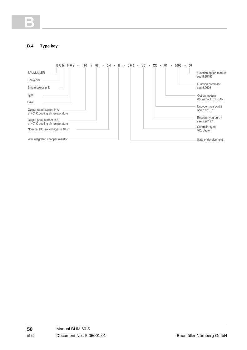
B.4 Type keyManual BUM 60 S
Document No.: 5.05001.01 Baumüller Nürnberg GmbH
50of 60
C
APPENDIX C - DECLARATION OFCONFORMITY / BY MANUFACTURER / UL - CERTIFICATION
In this section we provide general information about EU directives, the CE symbol and the Dec-laration of Conformity/by Manufacturer.
C.1 What is an EU directive?
EU directives specify requirements. The directives are written by the relevant bodies within the EU and are implemented by all the member countries of the EU in national law. In this way the EU directives guarantee free trade within the EU.
An EU directive only contains essential minimum requirements. You will find detailed require-ments in standards, to which references are made in the directive.
C.2 What the CE symbol indicates
a) The CE marking symbolizes conformity to all the obligations incumbent on manufacturers for the product by virtue of the Community directives providing for its affixing.…
b) The CE marking affixed to industrial products symbolizes the fact that the natural or legal per-son having affixed or been responsible for the affixing of the said marking has verified that the product conforms to all the Community total harmonization provisions which apply to it and has been the subject of the appropriate conformity evaluation procedures.…
Council Decision 93/465/EEC, Annex I B. a) + c)
We affix the CE mark to the equipment and to the documentation as soon as we have estab-lished that we have satisfied the requirements of the relevant directives.
All converters and control systems supplied by the Baumüller Nürnberg GmbH satisfy the re-quirements of 73/23/EEC (Low Voltage Directive). As all converters and control systems comply with the requirements of the harmonized stan-dards EN50178, EN 60204-1, EN 60529 and HD625.1 S1, the protection targets of 73/23/EWG are reached.
51of 60
Manual BUM 60 SDocument No.: 5.05001.01
Definition of the term Declaration of ConformityC.3
With specified application of this Baumüller equipment in your machinery, you can act on the assumption that the equipment satisfies the requirements of 98/37/EG (machinery directive). Therefore the equipment is developed and constructed in such a way, that the requirements of the harmonized standard EN 60204-1 can be met by the electrical installation.
Compliance with 89/336/EEC (EMC Directive) depends on how the equipment is installed. Since you are performing installation yourself, it is you who are responsible for complying with 89/336/EEC. A declaration of conformity on the EMC directive therefore cannot be issued.
We will provide you with support in the form of EMC information. You will find this information in the operating manual and in “filters for main applications”. When you have complied with all the requirements we impose in this documentation, you can assume that the drive satisfies the re-quirements of the EMC Directive. The limit values and requirements for variable-speed electrical drives are determined in the har-monized product standard EN61800-3. If you are erecting an installation, for which a declaration of conformity on the EMC directive must be generated, it may be necessary to specify several harmonized standards, which you have used for the compliance of the protection targets of the directive. The harmonized product standard EN 61800-3 has to be used with electrical drives.
To enable you to market your machine within the EU, you must be in possession of the following:
m Conformity mark (CE mark)
m Declaration(s) of Conformity regarding the directive(s) relevant to the machine
C.3 Definition of the term Declaration of Conformity
A Declaration of Conformity as defined by this documentation is a declaration that the electrical equipment brought into circulation conforms to all the relevant fundamental safety and health requirements.
By issuing the Declaration of Conformity in this section the Baumüller Nürnberg GmbH declares that the equipment conforms to the relevant fundamental safety and health requirements result-ing from the directives and standards which are listed in the Declaration of Conformity.
C.4 Definition of the term Declaration by Manufacturer
A Declaration by Manufacturer as defined by this documentation is a declaration that the ma-chine/safety component brought into circulation conforms to all the relevant fundamental safety and health requirements.
By issuing the Declaration of Conformity in this section the Baumüller Nürnberg GmbH declares that the equipment conforms to the relevant fundamental safety and health requirements result-ing from the directives and standards which are listed in the Declaration of Conformity .
The Baumüller equipment is integrated into a machine. For health and safety, of the users for example, it is important for the entire machine to conform to all the relevant fundamental safety and health requirements. For this reason the Baumüller Nürnberg GmbH draws attention in the Declaration by Manufacturer to the fact that it is prohibited to put the machine as a whole into operation before it has been declared that the machine conforms to the provisions of the Ma-chinery Directive.
Manual BUM 60 S
Document No.: 5.05001.01 Baumüller Nürnberg GmbH
52of 60
Declaration of Conformity / by Manufacturer / UL - Certification C
C.5 Declaration of conformityEG-KonformitätserklärungDeclaration of conformity
gemäß EG-Richtlinie 72/23/EG (Niederspannung) vom 19.02.1973 geändert durch: 93/68/EWG vom 22.07.1993
in accordance with EC directive 72/23/EG (low voltage) dated 19.02.1973 changed by: 93/68/EWG dated 22.07.1993
Einzel-Leistungs-Einheit (Mono Power Unit)BUM 60 S - XX/XX - 54 - X - XXX
Das obige Gerät wurde entwickelt und konstruiert sowie anschließend gefertigt in Übereinstim-mung mit o.g. EG-Richtlinie und u.g. Normen in alleiniger Verantwortung von: the unit specified above was developed and constructed as well as manufactured in accordance with the above mentioned directive and the standards mentioned below under liability of:
Baumüller Nürnberg GmbH, Ostendstr. 80 - 90, 90482 Nürnberg, Germany
Berücksichtigte Normen - standards complied with:
Nürnberg, 28.01.2005
Andreas Baumüller ppa. Dr. Peter Heidrich Geschäftsführer Entwicklungsleiter Head Division Head of development
Norm / standard
EN 50178 Ausrüstung von Starkstromanlagen mit elektrischen Betriebsmitteln Electronic equipment for use in power installations
EN 60204-1 Sicherheit von Maschinen - Elektrische Ausrüstung von Maschinen Safety of machinery - Electrical equipment of machines
EN 60529 Schutzarten durch Gehäuse (IP Code) Degrees of protection provided by enclosures (IP Code)
HD 625.1 51 Isolationskoordination für elektrische Betriebsmittel in Niederspannungsanlagen Insulation coordination for equipment within low-voltage systems
Manual BUM 60 SDocument No.: 5.05001.01
53of 60
Declaration by manufacturerC.6
C.6 Declaration by manufacturer
EG-HerstellererklärungDeclaration by manufacturer
gemäß EG-Richtlinie 98/37/EG (Maschinen) vom 22.06.1998 geändert durch: 98/79/EG vom 27.10.1998
in accordance with EC directive 98/37/EG (machinery) dated 22.06.1998 changed by: 98/79/EC dated 27.10.1998
Einzel-Leistungs-Einheit (Mono Power Unit)BUM 60 S - XX/XX - 54 - X - XXX
Das obige Bauteil wurde entwickelt und konstruiert sowie anschließend gefertigt in Übereinstim-mung mit o.g. EG-Richtlinie und u.g. Normen in alleiniger Verantwortung von: The part specified above was developed and constructed as well as manufactured in accord-ance with the above mentioned directive and the standards mentioned below under liability of:
Baumüller Nürnberg GmbH, Ostendstr. 80 - 90, D- 90482 Nürnberg
Berücksichtigte Normen - standards complied with:
Die Inbetriebnahme der Maschine, in die dieses Bauteil eingebaut wird, ist untersagt bis die Konformität der Maschine mit der obengenannte Richtlinie erklärt ist. The machinery into which this part is to be incorporated must not be put into service until the machinery has been declared in conformity with the provisions of the directive mentioned above.
Nürnberg, 28.01.2005
Andreas Baumüller ppa. Dr. Peter Heidrich Geschäftsführer Entwicklungsleiter Head Division Head of development
Norm / standard
EN 60204-1 Sicherheit von Maschinen - Elektrische Ausrüstung von Maschinen Safety of machinery - Electrical equipment of machines
Manual BUM 60 S
Document No.: 5.05001.01 Baumüller Nürnberg GmbH
54of 60
Declaration of Conformity / by Manufacturer / UL - Certification C
C.7 UL-certificationUL is a mark of conformity, which is assigned from Underwriters Laboratories Inc. (www.ul.com), an American company. The UL-certification is not statutory regulated, but takes place voluntarily. In order to be allowed to mark equipments and components with the UL-mark of confomity, tests must have to be done, which are attended and documentated by an UL-inspector. Only if all nec-essary tests have been passed and regular product monitoring at the production process of the equipment or the components has been passed without objections, the UL-mark of conformity may be attached to the equipment under test. Line filters of the company Baumüller Nürnberg GmbH are checked in accordance of the UL-standard UL 508C (UL-Standard for Safety for Power Conversion Equipment) and are recorded under the category control number NMMS. The product- and test description is recorded under file-no. E179860.
Only if all necessary tests have been completely carried out the c-mark may be attached to the equipments or components. If single tests have not already taken place at the manufacturer´s, but are carried out not until at the user´s, then only the u-mark may be attached. With products of the Baumüller Nürnberg GmbH all tests are already completed at the UL-cer-tification process, so that they may be marked with the c-mark.
In case with the UL-certification process also standards of the CSA (Canadian Standard Asso-ciation) are considered, then instead of the c- or u-mark the cc or U-mark may be at-tached to the product. With products of the company Baumüller Nürnberg GmbH the CSA-standard Norm C 22.2 was considered, that´s why they are marked with the cc-mark.
If products of Baumüller Nürnberg GmbH are mounted into an UL-certified installation, then cer-tain application-, mounting- and installation notices must be considered, which are upon the functioning of the device. We have marked these notes in the manual with „UL 508C ...“. Only if you follow these notes and apply to them you may go by it, that the installation has been mount-ed UL-conform.
Manual BUM 60 SDocument No.: 5.05001.01
55of 60

UL-certificationC.7
Manual BUM 60 S
Document No.: 5.05001.01 Baumüller Nürnberg GmbH
56of 60
Index
Numerics73/23/EWG 51
AAccessories 32
BBlock diagram 7
CCable screens 24Cabling 21Cases of operation
provided 11Checks with high voltages 11Chopper circuit 6Coolant temperature 17
DDeclaration by Manufacturer 51Declaration of Conformity 51Degree of pollution 17
EEMC instructions 21EMC regulation (EMVG) 21EMC-stack 32
FFunctional description 6Fuses 49
GGrounding 24
HHeat sources
additional 17
IInrush-current limiting 6
JJunction temperature 36
LLow Voltage Directive 51
MMaintenance notes 41Monitoring
chopper resistor 35DC-link 36ground current 36heatsink temperature 37infeed converter 35motor-sided inverter 36phase failure 35power failure 35power transistors 36precondition 35
Motor-sided inverter 6
OOperation 35Overcurrent message 36
PPacking 13Plug-in terminal 32
QQualified personnel 9
RRecommissioning 42Required environmental conditions 47
SScreening 25Supply converter 6
TTransport damage 13Transportation 13Type key 50
UUL-certification 55
Manual BUM 60 SDocument No.: 5.05001.01
57of 60

Manual BUM 60 S
Document No.: 5.05001.01 Baumüller Nürnberg GmbH
58of 60
Table of figures
Block diagram BUM 60 S ............................................................................................................. 7Cabling power unit ..................................................................................................................... 22Cable laying - aerial height......................................................................................................... 23Cable laying - loop area ............................................................................................................. 23Cable laying - cabinet outlet ....................................................................................................... 24Cable laying - to apply screen.................................................................................................... 25Proposal for screening connection............................................................................................. 26Screening terminals for grounding ............................................................................................. 27
Manual BUM 60 SDocument No.: 5.05001.01
59von 60
60of 60
Table of figures
Manual BUM 60 S
Document No.: 5.05001.01 Baumüller Nürnberg GmbH


Baumüller Nürnberg GmbH Ostendstraße 80-90 90482 Nürnberg T: +49(0)911-5432-0 F: +49(0)911-5432-130 www.baumueller.de
All information given in this manual is customer information, subject to change without notice. We reserve the right to futher develop and actualize our products continuously using our permanent revision service. Please notice, that specifications/data/information are current values according to the printing date.These statements are not legally binding according to the measurement, computation and calculations. Before you make any information given in this manual to the basis of your own calculations and/or applications, please make sure that you have the latest edition of the information in hand.No liability can be accepted concerning the correctness of the information.