Embed Size (px)
Citation preview

J STAGE Advance Publication date: 8 August, 2016Paper No.16-00334
© 2016 The Japan Society of Mechanical Engineers[DOI: 10.1299/mej.16-00334]
Vol.3, No.5, 2016Bulletin of the JSME
Mechanical Engineering Journal
0123456789
-
Material and heat flow analysis in thermal energy storage and
transport system utilizing unused heat from bagasse boiler
Shoma FUJII*, Yuichiro KANEMATSU**, Yasunori KIKUCHI** and Takao NAKAGAKI* *Department of Modern Mechanical Engineering, Waseda University
3-4-1 Okubo, Shinjuku-ku, Tokyo 169-8555, Japan
E-mail: [email protected]
**Presidential Endowed Chair for “Platinum Society”, The University of Tokyo
7-3-1 Hongo, Bunkyo-ku, Tokyo 113-0033, Japan
1. Introduction
Isolated areas such as islands rely on imported fossil fuels to a greater extent than in other areas; the sustainability
of industry in these areas decreases day by day. “Industrial Symbiosis”, which is a concept for utilizing the unused
materials and energy from one industry in neighboring industries, has become important in alleviating these issues
(Kikuchi et al., 2016). Tanegashima is an isolated island located south of Kyushu in Japan; the cultivation and milling of
sugarcane is the main industry. A sugar mill produces raw sugar which is shipped to a domestic sugar refinery in Osaka,
and a large amount of bagasse. Bagasse is fibrous residue obtained from milled sugarcane after the sugar juice has been
extracted, and the bagasse boiler of the sugar mill combusts the bagasse as a biomass energy. Bagasse is a useful biomass
energy source with an established collection system. However, it is difficult to store raw bagasse because its moisture
content causes it to be perishable. Accordingly, more bagasse is burned in the bagasse boiler than is required for mill
turbine and power generation. Hence, the temperature of the flue gas is high, and a large amount of unused heat at
approximately 200 °C is exhausted during mill operation, typically from December to April.
There are many other factories in Tanegashima, such as a liquor factory, which generally use oil-fired package boilers
to generate process steam at temperatures up to 120 °C and a total amount of heat demand at the liquor factory is 1556
GJ/year. Furthermore, the affiliate sugar-refinery in Osaka uses city gas boilers to constantly generate a large quantity of
steam at 150 °C for the crystallization and refining processes and a total amount of heat demand at the sugar refinery is
315315 GJ/year.
Abstract
Sugar production is the main industry in Tanegashima, Japan. Whilst the sugar mill recycles sugarcane bagasse
as a fuel, it concurrently generates large amounts of unused 200 °C heat during operation. Raw sugar is
shipped to a refinery in Osaka for the final stages of production, which uses a city gas boiler to continuously
generate a large quantity of 150 °C heat. However, factories in Tanegashima need a continuous supply of
process steam at temperatures of up to 120 °C. To resolve this spatial and seasonal mismatch of heat, we
propose a thermal energy storage and transport system using a zeolite adsorption/regeneration cycle. A process
flow diagram of the sugar mill has been developed, and the amount of available heat, the potential storage
capacity, and the transportable amount of heat have been calculated. Two scenarios were analyzed, in which
the stored heat is shipped to Osaka, or used on the island. This was achieved by calculating the rate-based
storage capacity of zeolite, based upon an adsorption and regeneration test. The transportable quantity of
zeolite determines the feasibility of using waste heat. In the first case, transport of heat to the sugar refinery in
Osaka has little possibility of being implemented. In the second case, transport of heat to a liquor factory in
Tanegashima can potentially reduce its usage of heavy oil by 83 %, equivalent to 33 kL/year.
Key words: Heat storage, Biomass energy, Zeolite adsorption and regeneration cycle, Sugarcane bagasse,
Sugar milling process, Unused heat utilization
Received 30 May 2016
1

2© 2016 The Japan Society of Mechanical Engineers
Fujii, Kanematsu, Kikuchi and Nakagaki, Mechanical Engineering Journal, Vol.3, No.5 (2016)
[DOI: 10.1299/mej.16-00334]
The sugar mill is operated from winter to spring according to the sugarcane harvest, however other factories including
the liquor factory and the sugar refinery are operated all year around with the constant heat demand. If unused heat from
the bagasse boiler in the sugar mill can compensate for the heat demand supplied by boilers, both the fossil fuel and the
accompanying CO2 emissions can be reduced. In order to resolve the spatial and seasonal mismatch, we propose a thermal
energy storage (TES) and transport system using zeolite steam adsorption and regeneration cycle as shown in Fig. 1.
Many TES systems have already been reported. L. F. Cabeza et al. summarized CO2 reduction for a variety of TES
case studies, including a solar power plant, and mobile heat storage (Cabeza et al., 2015). “Heat on wheels”, transporting
unused heat by truck using PCM (Phase Change Material) in Sweden was assessed from a technical and economic
perspective (IEA ECES annex 25, 2015). This system has the potential to overcome pipe-based systems for wide area
heat distribution. However, PCM is not suitable for Tanegashima because PCM cannot resolve a seasonal mismatch.
TES technology using materials with a reversible process is the only solution to allow for a seasonal mismatch, and
can be classified in terms of reversible chemical reactions, or physical adsorption and desorption cycling. Oguraa et al.
proposed an energy recycling system using calcium sulfate, which is a typical thermochemical energy storage material
using reversible hydration and dehydration reactions. It was shown that a system that used a chemical heat pump container
was more efficient than similar transportation systems, which used latent heat storage and sensible heat storage systems
(Oguraa, 2012). Heat storage materials that use chemical reactions still have a few problems, while they also have some
attractive features such as large heat storage capacity and high-temperature capability. One of the problems is degradation
because of cumulative chemical compounds produced by irreversible reactions with minor contaminants. Another
problem is the difficulty in controlling reaction rates because of positive feedback between the exothermic heat release
reactions and the Arrhenius law. Physical adsorption materials such as zeolite have advantages from this perspective, so
we selected zeolite as a storage media for the Tanegashima case. Krönauer et al. demonstrated a TES and transport system
using zeolite (Krönauer et al., 2015). Zeolite was regenerated by extraction of steam from a waste incineration plant, and
supplied adsorption heat for a gas-fired drying process located 7 km from the storage station. They reported that the
energy storage capacity achieved 2.3 MWh, and 616 kg per cycle CO2 emissions could be reduced in comparison with
the conventional plant operation. Also, the results showed that it was possible to overcome cost barriers against oil and
gas by using 50 tons of zeolite. IEA ECES annex 18 summarized the price per MWh heat comparing the adsorption
system with PCM and hot water storage. It was clearly shown that the adsorption system is capable of overcoming the
cost barrier against the oil and natural gas (IEA ECES annex 18, 2010).
This study analyzes material and heat flow in two TES and transport systems using a zeolite adsorption and
regeneration cycle applied to the unused heat from the sugar mill. The first case supplies heat between the sugar mill in
Tanegashima and the sugar refinery in Osaka; the second case supplies heat to a local liquor factory in Tanegashima.
Fig. 1 Concept of TES & Transport system
2
2© 2016 The Japan Society of Mechanical Engineers
Fujii, Kanematsu, Kikuchi and Nakagaki, Mechanical Engineering Journal, Vol.3, No.5 (2016)
[DOI: 10.1299/mej.16-00334]
2. Process flow diagram of the sugar mill
Figure 2 is a schematic of the sugar mill in Tanegashima around the bagasse boiler. Bagasse is fired in the bagasse
boiler as fuel, and the combustion heat generates steam to drive a mill turbine and a steam turbine which supplies
electricity for the sugar mill. The latent heat of the exhaust steam flows from the mill and steam turbines are used in the
evaporators and crystallizers for raw sugar making. Flue gas is exhausted from the stack after electrostatic precipitation.
To calculate the potential storage capacity of zeolite, the flow of unused heat has to be quantified by the analysis of mass
and heat balance for the sugar mill.
The heating value of dried bagasse Hh-dry and wet bagasse Hh-wet were estimated using Eq. (1) (Klass, 2004) and (2):
70.271.45 cH dryh (1)
)1( wHH dryhweth (2)
where c is the mass fraction of carbon in dried
bagasse and w is the moisture content of wet bagasse.
The mass fraction of carbon and moisture content of
bagasse were determined by an elemental analysis
and a drying test, respectively. Wet bagasse samples
were dried in an electric furnace, and the change in
sample weight was measured. Then, the dried bagasse
samples were pulverized into powder and analyzed by
elemental analysis. The moisture content of bagasse
and the lower heating value of wet bagasse Hl were
determined by Eq. (3) and (4):
wet
drywet
m
mmw
(3)
)9(44.2 whHH wethl (4)
where mwet and mdry are the mass of wet and dried bagasse, and h is the mass fraction of hydrogen in the dried bagasse,
obtained by elemental analysis. Table 1 shows the results of the elemental analysis, the bagasse drying test and the heating
values of bagasse.
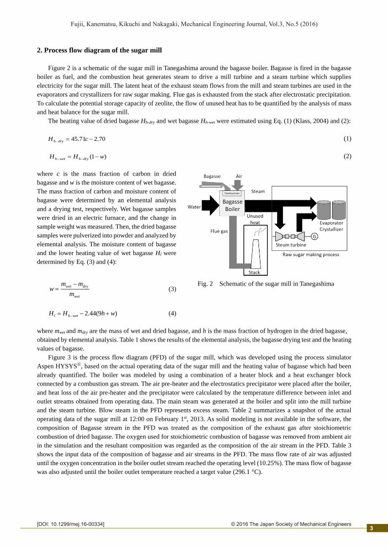
Figure 3 is the process flow diagram (PFD) of the sugar mill, which was developed using the process simulator
Aspen HYSYSⓇ, based on the actual operating data of the sugar mill and the heating value of bagasse which had been
already quantified. The boiler was modeled by using a combination of a heater block and a heat exchanger block
connected by a combustion gas stream. The air pre-heater and the electrostatics precipitator were placed after the boiler,
and heat loss of the air pre-heater and the precipitator were calculated by the temperature difference between inlet and
outlet streams obtained from operating data. The main steam was generated at the boiler and split into the mill turbine
and the steam turbine. Blow steam in the PFD represents excess steam. Table 2 summarizes a snapshot of the actual
operating data of the sugar mill at 12:00 on February 1st, 2013. As solid modeling is not available in the software, the
composition of Bagasse stream in the PFD was treated as the composition of the exhaust gas after stoichiometric
combustion of dried bagasse. The oxygen used for stoichiometric combustion of bagasse was removed from ambient air
in the simulation and the resultant composition was regarded as the composition of the air stream in the PFD. Table 3
shows the input data of the composition of bagasse and air streams in the PFD. The mass flow rate of air was adjusted
until the oxygen concentration in the boiler outlet stream reached the operating level (10.25%). The mass flow of bagasse
was also adjusted until the boiler outlet temperature reached a target value (296.1 °C).
Fig. 2 Schematic of the sugar mill in Tanegashima
3
2© 2016 The Japan Society of Mechanical Engineers
Fujii, Kanematsu, Kikuchi and Nakagaki, Mechanical Engineering Journal, Vol.3, No.5 (2016)
[DOI: 10.1299/mej.16-00334]
Table 2 Actual operating data of the sugar mill (At 12:00 on February 1, 2013)
Temperature
[°C]
Pressure
[kPa]
Mass flow
[ton/h]
Steam
Main steam 344.6 1853 27.26
Turbine inlet 343.7 1803 15.62
Turbine outlet 161.5 75
Mill turbine
342.8 -
8.38
Others 1.87
Blow steam 1.39
Exhaust
gas
Boiler outlet 296.1 101.7
Adjusted Air pre-heater 199.3 104.6
Precipitator 178.1 102.1
(ambient pressure)
Table 3 Composition of bagasse and air stream
Composition N2 O2 Ar H2O CO2 NO2
Bagasse - - - 0.2307 0.7668 0.0025
Air 0.8428 0.1330 0.0144 0.0092 0.0005 -
Fig. 3 Process flow diagram of the sugar mill
Table 1 Estimation of heating values of bagasse
Elemental analysis of dried bagasse [wt%] Moisture
[wt%]
Hhd
[MJ/kg]
Hhw
[MJ/kg]
Hl
[MJ/kg] C H N O
46.12 5.69 0.17 48.02 44.38 18.38 10.22 8.445
4
2© 2016 The Japan Society of Mechanical Engineers
Fujii, Kanematsu, Kikuchi and Nakagaki, Mechanical Engineering Journal, Vol.3, No.5 (2016)
[DOI: 10.1299/mej.16-00334]
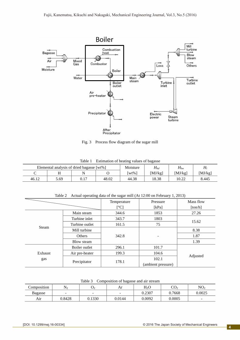
3. Potential storage capacity
3.1 Current process (wet bagasse process)
From the analysis of the mass and heat balance for the sugar mill, the flow of unused heat was calculated. Figure 4
shows a schematic of the regeneration-air heater to desorb the water molecules of zeolite using hot air. The regeneration-
air heater was placed after the electrostatic precipitator and heated by the flue gas. Ambient air was compressed to 110
kPa and heated to 138 °C by the flue gas via an air heater. The mass flow rate of the steam for the turbine was increased
according to the additional electricity used for the compressor. The minimum temperature approach between
regeneration-air and flue gas was assumed to be 40 °C. The flow of unused heat was calculated using the temperature
difference between the flue gas and ambient air. The heat duty of the regeneration-air heater, which can be translated into
“Potential storage capacity” was also calculated using the process simulator. As a result, the flow of unused heat and
potential storage capacity were 9.7 GJ/h and 1.8 GJ/h, respectively as shown in Fig. 4.
3.2 Dried bagasse process
In general, bagasse has a high moisture content as shown in Table 1, so it is important to improve the calorific value
of bagasse as a fuel by applying a drying process. Therefore, the PFD of the wet bagasse process was modified, and the
increase in the unused heat of flue gas was quantified. The mass flow rate of moisture-free bagasse drybm
can be
expressed by the following equation:
)1( wmm wetbdryb (5)
where wetbm is the mass flow rate of bagasse in the wet bagasse process. Then, the overall heat transfer coefficient of
the boiler was recalculated using the mass flow and inlet temperature of the combusted gas. The air ratio was kept as
1.741, which was similar to the wet bagasse process.
By applying the dried bagasse process, the flue gas temperature of the boiler outlet was increased to 465 °C. To cool
the flue gas down to a temperature lower than the maximum allowable temperature of the precipitator (350 °C), the
regeneration-air heater was moved upstream of the electrostatic precipitator, as shown in Fig. 5. The heat loss at the
precipitator was assumed to be equal to that of the wet bagasse process. To avoid the acid dew point, the temperature of
the flue gas exhausts from the stack was set to the same value as the wet bagasse process (150 °C). As a result, the flow
of unused heat and potential storage capacity were 22.2 GJ/h and 10.1 GJ/h, respectively as shown in Fig. 5.
Fig. 4 Schematic of the regeneration-air heater and Sankey diagram for the wet bagasse process
5

2© 2016 The Japan Society of Mechanical Engineers
Fujii, Kanematsu, Kikuchi and Nakagaki, Mechanical Engineering Journal, Vol.3, No.5 (2016)
[DOI: 10.1299/mej.16-00334]
Fig. 5 Schematic of the regeneration-air heater and Sankey diagram for the dried bagasse process
4. Rate-based storage capacity based on adsorption / regeneration tests
In the previous section, the flow of unused heat and the potential storage capacity were calculated. However, the total
amount of the potential storage capacity cannot be stored in zeolite because the rate-based storage capacity is limited by
the regeneration rate of zeolite. This was quantified experimentally by regeneration tests using a fixed bed packed with
zeolite 13X particles (F-9 zeolite, TOSOH CORPORATION). Also, the adsorption test was conducted to saturate the
zeolite with water before the regeneration tests and the data concerning adsorption amount and adsorption isotherms were
obtained simultaneously.
4.1 Experimental apparatus
The experimental apparatus was based on the design of Simo et al. (Simo, 2009). Figure 6 shows the apparatus used
for the adsorption and regeneration tests. Air was supplied from a compressed air cylinder, the flow rate of which was
controlled by a mass flow controller (Model: FLOW COMPO MODEL 3660, 10SCCM-20SLM, KOFLOC, Japan). The
air was humidified by a humidity conditioning unit which consisted of a mantle heater/ stirred flask (Model: MS-ES-3
300mL, AS ONE, Japan) and a 300 mL flask, as shown in Fig. 6. The humidity of the air was controlled by changing the
water temperature in the flask. The humidified air was heated using ribbon heaters and the temperature of the humidified
air at the inlet of the reactor was measured by thermocouple 1 (TC1) and controlled using a temperature controller. A 1/2
inch stainless steel tube packed with 15 grams of zeolite was placed into the electric furnace. The air temperature at the
outlet of the reactor was also measured by thermocouple 2 (TC2).
Adsorption isotherm data were obtained from the adsorption tests at 130 °C. These were operated at a range of
water temperatures in the flask from 20 °C (partial pressure ~ 2.3 kPa) to 50 °C (~12 kPa). After the humidity of the air
Fig. 6 Experimental apparatus Fig. 7 Adsorption isotherms
6
2© 2016 The Japan Society of Mechanical Engineers
Fujii, Kanematsu, Kikuchi and Nakagaki, Mechanical Engineering Journal, Vol.3, No.5 (2016)
[DOI: 10.1299/mej.16-00334]
reached a steady state, humidified air was poured into the reactor and the change of outlet humidity was measured and
logged by a humidity transmitter (Model: HF 53, ROTORONIC, Switzerland) every 5 seconds until the vapor pressure
returned to the initial condition.
Regeneration tests were conducted after the adsorption tests at 70 °C. Dry air supplied from the compressed air
cylinder was poured into the reactor and the outlet humidity change was measured.
4.2 Adsorption test
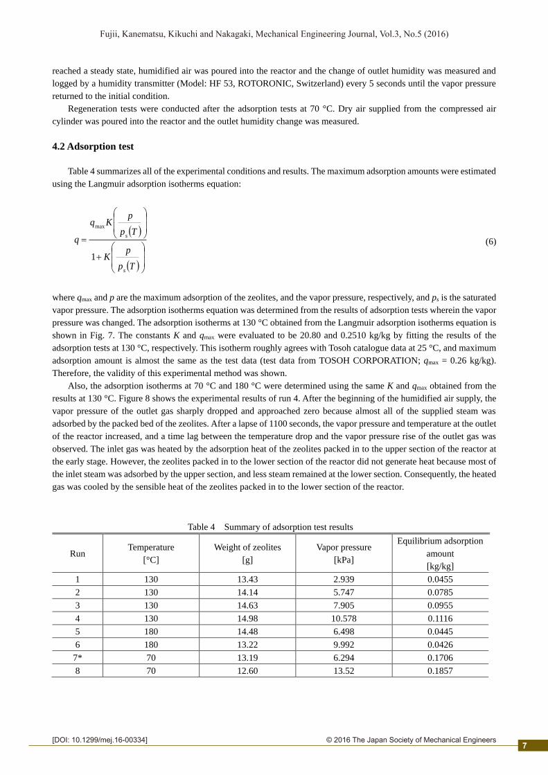
Table 4 summarizes all of the experimental conditions and results. The maximum adsorption amounts were estimated
using the Langmuir adsorption isotherms equation:
Tp
pK
Tp
pKq
q
s
s
1
max
(6)
where qmax and p are the maximum adsorption of the zeolites, and the vapor pressure, respectively, and ps is the saturated
vapor pressure. The adsorption isotherms equation was determined from the results of adsorption tests wherein the vapor
pressure was changed. The adsorption isotherms at 130 °C obtained from the Langmuir adsorption isotherms equation is
shown in Fig. 7. The constants K and qmax were evaluated to be 20.80 and 0.2510 kg/kg by fitting the results of the
adsorption tests at 130 °C, respectively. This isotherm roughly agrees with Tosoh catalogue data at 25 °C, and maximum
adsorption amount is almost the same as the test data (test data from TOSOH CORPORATION; qmax = 0.26 kg/kg).
Therefore, the validity of this experimental method was shown.
Also, the adsorption isotherms at 70 °C and 180 °C were determined using the same K and qmax obtained from the
results at 130 °C. Figure 8 shows the experimental results of run 4. After the beginning of the humidified air supply, the
vapor pressure of the outlet gas sharply dropped and approached zero because almost all of the supplied steam was
adsorbed by the packed bed of the zeolites. After a lapse of 1100 seconds, the vapor pressure and temperature at the outlet
of the reactor increased, and a time lag between the temperature drop and the vapor pressure rise of the outlet gas was
observed. The inlet gas was heated by the adsorption heat of the zeolites packed in to the upper section of the reactor at
the early stage. However, the zeolites packed in to the lower section of the reactor did not generate heat because most of
the inlet steam was adsorbed by the upper section, and less steam remained at the lower section. Consequently, the heated
gas was cooled by the sensible heat of the zeolites packed in to the lower section of the reactor.
Table 4 Summary of adsorption test results
Run Temperature
[°C]
Weight of zeolites
[g]
Vapor pressure
[kPa]
Equilibrium adsorption
amount
[kg/kg]
1 130 13.43 2.939 0.0455
2 130 14.14 5.747 0.0785
3 130 14.63 7.905 0.0955
4 130 14.98 10.578 0.1116
5 180 14.48 6.498 0.0445
6 180 13.22 9.992 0.0426
7* 70 13.19 6.294 0.1706
8 70 12.60 13.52 0.1857
7

2© 2016 The Japan Society of Mechanical Engineers
Fujii, Kanematsu, Kikuchi and Nakagaki, Mechanical Engineering Journal, Vol.3, No.5 (2016)
[DOI: 10.1299/mej.16-00334]
4.3 Regeneration test
Figure 9 shows the results of the regeneration test after the adsorption test at 70 °C (run 7). In the regeneration tests,
the air temperature at the outlet of the reactor was not recorded because the temperature change was minimal. A residue
adsorption amount of 0.1 kg/kg was assumed in this system, then, the vapor pressure corresponding to an adsorption
amount of 0.1 kg/kg was calculated (0.987 kPa) using the Langmuir equation that had been already obtained from
adsorption tests, and the time until the vapor pressure fell below 0.987 kPa was regarded as the regeneration time t (=
2915 sec). The air flow rates required for regenerating 1 gram of adsorbed vapor from zeolite at 70 °C was calculated
using Eq. (7):
)1.0*(*
qm
tFV
z
MFCreg (7)
where FMFC is the air flow rate controlled by the mass flow controller. And mz* and q* are the amount of zeolite and
adsorbed vapor at run 7 of adsorption test, respectively. The regeneration rate r was calculated using Eq. (8) and the
amount of zeolites which could be regenerated at the sugar mill mz in Tanegashima was calculated using Eq. (9):
310reg
PFD
V
Fr (8)
)1.0( max
q
rmz (9)
where FPFD is the equilibrium air flow rate of regeneration-air in PFD. The rate-based storage capacity QR of both wet
and dried bagasse processes were calculated using Eq. (10):
HΔrQR (10)
where ΔH is adsorption heat of zeolite 13X which is measured in other literature (Nakaso et al., 2011). The results of
regeneration rates and rate-based storage capacity are shown in Table 5.
Fig. 8 Change in vapor pressure and temperature of the
outlet gas with time in the adsorption test
Fig. 9 Change in vapor pressure with time in the
regeneration test at 70 °C
100
110
120
130
140
150
160
170
0
2
4
6
8
10
12
0 1000 2000 3000 4000 5000
Tem
per
atu
re °
C
Vap
or
pre
ssu
re k
Pa
Time s
Vapor pressure
Temperature
0
1
2
3
4
5
6
7
0 2000 4000 6000 8000
Vap
or
pre
ssu
re k
Pa
Time sRegeneration time
2915
0.987
8

2© 2016 The Japan Society of Mechanical Engineers
Fujii, Kanematsu, Kikuchi and Nakagaki, Mechanical Engineering Journal, Vol.3, No.5 (2016)
[DOI: 10.1299/mej.16-00334]
5. Results
5.1 CASE 1 (Transport to the sugar refinery in Osaka)
The sugar refinery in Osaka uses city gas boilers to generate steam at 150 °C for the crystallization and refining
process all year around. Operating time of the sugar mill and the sugar refinery are 3000 hours and 6840 hours (285 days
× 24 hours), respectively. The transportable quantity of the zeolite was calculated using the operating data of the weekly
cargo shipments between Tanegashima and Osaka. The maximum load capacity of the cargo ship is 1,200 tons; 700 tons
of which are raw sugars transported to Osaka. Assuming use of the surplus load capacity of the cargo ship, 500 tons/week
of heat transport container packed with zeolites can be transported. The weight ratio between container and zeolites was
assumed to 1:1. Transportable amount of heat, QT, was determined using Eq. (11):
ZTT QmQ (11)
where mT is the transportable mass of the zeolite which can be calculated as 250 tons from the previous assumption, and
Qz is the storage density of the zeolite, which can be expressed as the following equation:
664)1.0( max qHΔQZ [kJ/kg] (12)
where the residual adsorption of zeolite is assumed to be 0.1 kg/kg.
The results of the material and heat flow of the system in CASE 1 are shown in Tables 6, 7 and Fig. 10. Both the
potential and the rate-based storage capacity are too low against the heat demand at the sugar refinery, and the
transportable amount of heat is the minimum value and restricts the maximum available amount of heat. Fuel reduction
rate at the sugar refinery by applying the TES and transport system was calculated by Eq. (13):
100 εQ
Qf
D
T (13)
where QD is heat demand at the sugar refinery. The coefficient ε considering the sensible heat of zeolite was determined
using Eq. (14):
87.0)(
1AD
Z
pz
Q
TTcε (14)
where cpz is specific heat capacity of zeolite obtained from other literature (Nakaso et al., 2011), and TD is the required
temperature at the heat demand side. TA is the ambient temperature (25 °C). In this case, the sugar refinery is assumed as
a heat demand, and TD is 150 °C. The fuel reduction rate by applying the TES and transport system of CASE 1 results in
only 0.8% reduction in fuel usage, which is equivalent to 66,000 m3 city gas and has little impact on the fuel consumption
at Osaka.
Table 5 Summary of regeneration test results
Process Time
[sec]
FMFC
[m3/h]
Vreg
[m3/g]
FPFD
[m3/h]
r
[kg/h]
mz
[kg/h]
QR
[GJ/h]
Wet bagasse 2915
0.061
(1018 [ccm]) 0.0531
17963 338.3 2241 1.488
Dried bagasse 55380 1043 6907 4.588
9
2© 2016 The Japan Society of Mechanical Engineers
Fujii, Kanematsu, Kikuchi and Nakagaki, Mechanical Engineering Journal, Vol.3, No.5 (2016)
[DOI: 10.1299/mej.16-00334]
5.2 CASE 2 (Transport to the liquor factory in Tanegashima)
A liquor factory in Tanegashima, which operates a conventional package boiler, was used as an example model of
heat demand to estimate fuel savings by applying the TES and transport system. The rated flow rate and pressure of
saturated steam of the boiler are 1.0 ton/h and 0.6 MPa, respectively. Under normal operation, the liquor factory requires
0.8 ton/h process steam at temperatures around 120 °C. The amount of oil used by the liquor factory was assumed to be
40,000 L per year. The operating time of the boiler of the liquor factory was assumed to be 180 days per year. A
conventional 12-ton truck was selected for transportation and it was assumed that transportation truck was operated once
per operating day of the liquor factory. Tables 6, 7 and Fig. 10 summarize the results of the material and heat flow of the
system in CASE 2. The transportable amount of zeolite is the minimum value and restricts the maximum available amount
of heat through the system. The fuel reduction rate of the liquor factory achieved by applying TES and the transport
system results in about an 83% reduction in fuel usage, which is equivalent to 33 kL/year heavy oil. The coefficient ε
considering the sensible heat of zeolite increased to 0.90 by applying the required temperature at the liquor factory (TD =
120 °C) to Eq. (14).
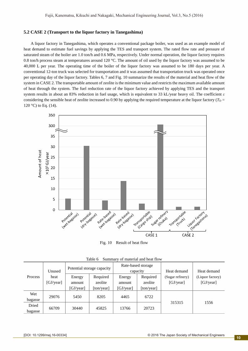
Fig. 10 Result of heat flow
Table 6 Summary of material and heat flow
Process
Unused
heat
[GJ/year]
Potential storage capacity Rate-based storage
capacity Heat demand
(Sugar refinery)
[GJ/year]
Heat demand
(Liquor factory)
[GJ/year]
Energy
amount
[GJ/year]
Required
zeolite
[ton/year]
Energy
amount
[GJ/year]
Required
zeolite
[ton/year]
Wet
bagasse 29076 5450 8205 4465 6722
315315 1556 Dried
bagasse 66709 30440 45825 13766 20723
10

2© 2016 The Japan Society of Mechanical Engineers
Fujii, Kanematsu, Kikuchi and Nakagaki, Mechanical Engineering Journal, Vol.3, No.5 (2016)
[DOI: 10.1299/mej.16-00334]
6. Conclusions
We proposed the introduction of a thermal energy storage and transport system for two different cases using a steam
adsorption and regeneration cycle of zeolite, and analyzed the material and heat flow by using commercial process
simulator “Aspen HYSYS®” and adsorption and regeneration tests. The main results of the analysis are summarized as
follows.
The flow of unused heat and potential storage capacity of the current process (wet bagasse process) of the sugar mill
were quantified. By applying the dried bagasse process, the temperature of flue gas was increased and the flow of unused
heat and potential storage capacity were increased. From zeolite adsorption and regeneration tests, adsorption isotherms,
maximum adsorption amount and approximate regeneration rate were quantified, then the rate-based storage capacity
was calculated.
In the first case the system was implemented between the sugar mill in Tanegashima and the sugar refinery in Osaka.
Heat storage capacity at the sugar mill is too low for the sugar refinery, and the transportable amount of zeolite by the
weekly cargo shipment restricts the maximum available amount of heat through the system in this case. It is difficult to
implement this system because of limited impact on the fuel consumption at the sugar refinery in Osaka.
In the second case we analyzed whether the system could provide heat for the local liquor factory, by using unused
heat from the sugar mill. The transportable amount of zeolite by truck also restricts the maximum available amount of
heat through the system in this case. However, the fuel consumption of the liquor factory reduced by 83%, which is
equivalent to 33 kL/year heavy oil, and this system has potential to give a considerable impact on the self-sufficiency of
local energy use.
Acknowledgments
The authors acknowledge the support of Shinko Sugar Mill Co., Ltd. and would like to express our gratitude.
References
Annex 18 – IEA/ECES, Transportation of energy by utilization of thermal energy storage technology, Final report,
(2010)
Annex 25 – ECES IA - IEA, Surplus heat management using advanced TES for CO2 mitigation, Final report, (2014)
Cabeza, L. F., Miró, L., Oró, E., Gracia, A., Martin, V., Krönauer, A., Rathgeber, C., M. Farid, M., O. Paksoy, H.,
Martínez, M. and Inés Fernández, A., CO2 mitigation accounting for thermal energy storage (TES) case studies.
Applied Energy, Vol.155 (2015), DOI:10.1016/j.apenergy.2015.05.121
Kikuchi, Y., Kanematsu, Y., Ugo, M., Hamada, Y. and Okubo, T., Industrial symbiosis centered on a regional cogeneration
power plant utilizing available local resources: A case study of Tanegashima, Journal of Industrial Ecology, Vol. 20,
Issue 2 (2016), DOI: 10.1111/jiec.12347
Klass, D. L., Biomass for Renewable Energy and Fuels, Encyclopedia of Energy, Vol 1 (2004), pp.193–212
Krönauer, A., E. Lävemann, S. Brückner, and A. Hauer., Mobile sorption heat storage in industrial waste heat recovery,
Energy Procedia, Vol.73, (2015), DOI:10.1016/j.egypro.2015.07.688
Table 7 Transportable amount of zeolite and energy
CASE 1 CASE 2
Load
capacity
[ton/week]
Raw sugar
[ton/week]
Surplus
[ton/week]
Transportable energy Load
capacity
[ton/cycle]
Transportable energy
[GJ/week] [GJ/year] [GJ/cycle] [GJ/year]
1200 700 500 166 2965 12 8.0 1434
11
2© 2016 The Japan Society of Mechanical Engineers
Fujii, Kanematsu, Kikuchi and Nakagaki, Mechanical Engineering Journal, Vol.3, No.5 (2016)
[DOI: 10.1299/mej.16-00334]
Nakaso, K., Okutariani, E., Noda, A., Itaya, Y., Nakagawa, T. and Fukai, J., Development of adsorption heat pump system
for regenerating high temperature steam – basic concept and estimation of effective utilization of energy-, Journal
of Japan Society of Energy and Resources (in Japanese), Vol. 32, No. 5 (2011), pp. 9–16.
Oguraa, H., Energy recycling system using chemical heat pump container., Energy Procedia Vol.14 (2012),
DOI:10.1016/j.egypro.2011.12.1206
Simo, M., Sivashanmugam, S., Brown, C. J., and Hlavacek, V., Adsorption/desorption of water and ethanol on 3A zeolite
in near-adiabatic fixed bed., Industrial and Engineering Chemistry Research, Vol. 48, No. 20 (2009), DOI:
10.1021/ie900446v
TOSOH CORPORATION, F-9 Zeolite H2O adsorption isotherms data (25 ˚C), (online), available from < http:
//www.tosoh.co.jp/zeolite/technology/pdfs/h2o_f9.pdf >, (accessed on 30 June, 2016)
Nomenclature
Symbol
subscript
c Mass fraction of carbon in dry bagasse [%] A Ambient
cp Specific heat capacity [kJ/kgK] b Bagasse
F Air flow rate [m3/h] D Demand
f Fuel Reduction rates [%] max Maximum
h Mass fraction of hydrogen in dry bagasse [%] dry Dried bagasse
Hh Higher Heating value of bagasse [MJ/kg] MFC Mass flow controller
Hl Lower heating value of wet bagasse [MJ/kg] PFD Process flow diagram
m Amount [kg/h] reg Regeneration
m Mass flow rate [kg/h] s Saturated
p pressure [kPa] T Transportable
Q Amount of heat [GJ/h] R Rate-based
q Adsorption amount [kg/kg] wet Wet bagasse
T Temperature [°C] z Zeolite
t Regeneration time [h]
V The volumetric air flow [m3/g]
w Moisture content of wet bagasse [%]
∆H Heat of adsorption (=4400 ) [kJ/kg]
12