Embed Size (px)
Citation preview
Catalogs > Industrial Controls Catalog > Relays, Timers, and Temperature Controllers > General Purpose Relays > Bulletin 700-HA Tube Base Relay
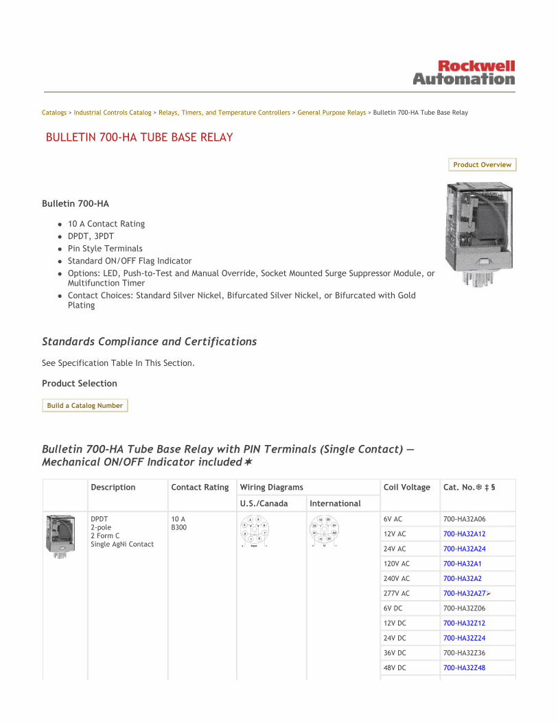
Bulletin 700-HA
10 A Contact Rating DPDT, 3PDT Pin Style Terminals Standard ON/OFF Flag Indicator Options: LED, Push-to-Test and Manual Override, Socket Mounted Surge Suppressor Module, or Multifunction Timer Contact Choices: Standard Silver Nickel, Bifurcated Silver Nickel, or Bifurcated with Gold Plating
Standards Compliance and Certifications See Specification Table In This Section. Product Selection
Bulletin 700-HA Tube Base Relay with PIN Terminals (Single Contact) — Mechanical ON/OFF Indicator included
BULLETIN 700-HA TUBE BASE RELAY
Product Overview
Build a Catalog Number
Description Contact Rating Wiring Diagrams Coil Voltage Cat. No. ‡ §
U.S./Canada International
DPDT 2-pole 2 Form C Single AgNi Contact
10 A B300
6V AC 700-HA32A06
12V AC 700-HA32A12
24V AC 700-HA32A24
120V AC 700-HA32A1
240V AC 700-HA32A2
277V AC 700-HA32A27
6V DC 700-HA32Z06
12V DC 700-HA32Z12
24V DC 700-HA32Z24
36V DC 700-HA32Z36
48V DC 700-HA32Z48

Bulletin 700-HAB Tube Base Relay with PIN Terminals (Bifurcated Contacts) — Mechanical ON/OFF Indicator included
60V DC 700-HA32Z60
80V DC 700-HA32Z80
110V DC 700-HA32Z1
125V DC 700-HA32Z01
Sockets 700-HN125 700-HN100 700-HN204
140V DC 700-HA32Z3
220V DC 700-HA32Z2
3PDT 3-pole 3 Form C Single AgNi Contact
10 A B300
6V AC 700-HA33A06
12V AC 700-HA33A12
24V AC 700-HA33A24
120V AC 700-HA33A1
240V AC 700-HA33A2
6V DC 700-HA33Z06
12V DC 700-HA33Z12
24V DC 700-HA33Z24
48V DC 700-HA33Z48
60V DC 700-HA33Z60
80V DC 700-HA33Z80
110V DC 700-HA33Z1
125V DC 700-HA33Z01
Sockets 700-HN126 700-HN101 700-HN205
140V DC 700-HA33Z3
220V DC 700-HA33Z2
For Time Module and Surge Suppressor Module, see Accessories. LED Option: Add suffix (-4) to the selected Bulletin 700-HA Relay Cat. No., except for the 240V AC Units, add (-4L).
‡ Push-to-test, Manual Override, and LED Option: Add suffix (-3-4) to the selected Bulletin 700-HA Relay Cat. No., except for the 240V AC units, add (-3-4L). § Push-to-test and Manual Override option: Add suffix (-3) to the selected Bulletin 700-HA relay. LED not available for 220V DC and 277V AC coils.
Description Contact Rating Wiring Diagrams Coil Voltage Cat. No. ‡ §
U.S./Canada International
DPDT 2-Pole 2 Form C Bifurcated AgNi Contacts
6 A
6V AC 700-HAB2A06
12V AC 700-HAB2A12
24V AC 700-HAB2A24
120V AC 700-HAB2A1
240V AC 700-HAB2A2
277V AC 700-HAB2A27
6V DC 700-HAB2Z06
12V DC 700-HAB2Z12
24V DC 700-HAB2Z24
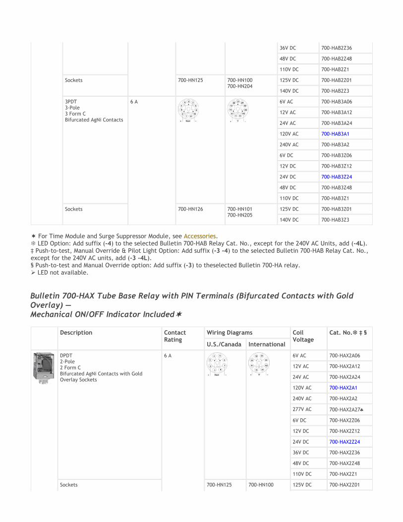
Bulletin 700-HAX Tube Base Relay with PIN Terminals (Bifurcated Contacts with Gold Overlay) — Mechanical ON/OFF Indicator Included
36V DC 700-HAB2Z36
48V DC 700-HAB2Z48
110V DC 700-HAB2Z1
Sockets 700-HN125 700-HN100 700-HN204
125V DC 700-HAB2Z01
140V DC 700-HAB2Z3
3PDT 3-Pole 3 Form C Bifurcated AgNi Contacts
6 A
6V AC 700-HAB3A06
12V AC 700-HAB3A12
24V AC 700-HAB3A24
120V AC 700-HAB3A1
240V AC 700-HAB3A2
6V DC 700-HAB3Z06
12V DC 700-HAB3Z12
24V DC 700-HAB3Z24
48V DC 700-HAB3Z48
110V DC 700-HAB3Z1
Sockets 700-HN126 700-HN101 700-HN205
125V DC 700-HAB3Z01
140V DC 700-HAB3Z3
For Time Module and Surge Suppressor Module, see Accessories. LED Option: Add suffix (-4) to the selected Bulletin 700-HAB Relay Cat. No., except for the 240V AC Units, add (-4L).
‡ Push-to-test, Manual Override & Pilot Light Option: Add suffix (-3 -4) to the selected Bulletin 700-HAB Relay Cat. No., except for the 240V AC units, add (-3 -4L). § Push-to-test and Manual Override option: Add suffix (-3) to theselected Bulletin 700-HA relay. LED not available.
Description Contact Rating
Wiring Diagrams Coil Voltage
Cat. No. ‡ §
U.S./Canada International
DPDT 2-Pole 2 Form C Bifurcated AgNi Contacts with Gold Overlay Sockets
6 A
6V AC 700-HAX2A06
12V AC 700-HAX2A12
24V AC 700-HAX2A24
120V AC 700-HAX2A1
240V AC 700-HAX2A2
277V AC 700-HAX2A27♣
6V DC 700-HAX2Z06
12V DC 700-HAX2Z12
24V DC 700-HAX2Z24
36V DC 700-HAX2Z36
48V DC 700-HAX2Z48
110V DC 700-HAX2Z1
Sockets 700-HN125 700-HN100 125V DC 700-HAX2Z01
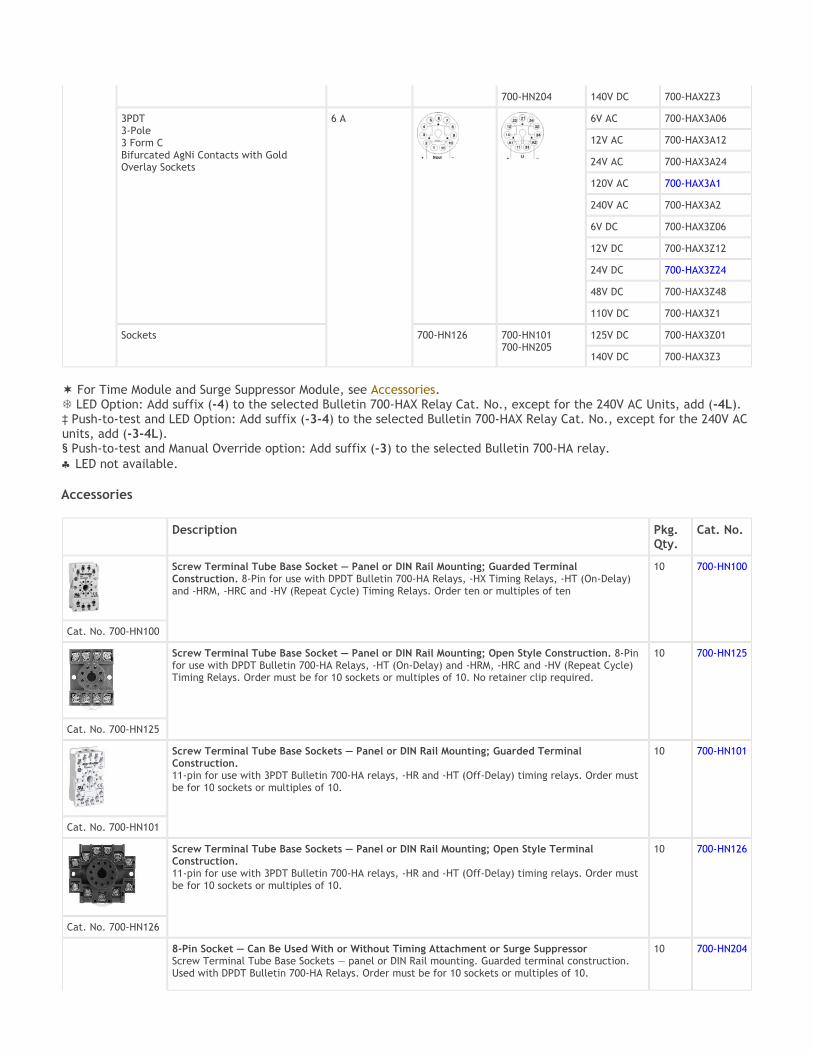
Accessories
700-HN204 140V DC 700-HAX2Z3
3PDT 3-Pole 3 Form C Bifurcated AgNi Contacts with Gold Overlay Sockets
6 A
6V AC 700-HAX3A06
12V AC 700-HAX3A12
24V AC 700-HAX3A24
120V AC 700-HAX3A1
240V AC 700-HAX3A2
6V DC 700-HAX3Z06
12V DC 700-HAX3Z12
24V DC 700-HAX3Z24
48V DC 700-HAX3Z48
110V DC 700-HAX3Z1
Sockets 700-HN126 700-HN101 700-HN205
125V DC 700-HAX3Z01
140V DC 700-HAX3Z3
For Time Module and Surge Suppressor Module, see Accessories. LED Option: Add suffix (-4) to the selected Bulletin 700-HAX Relay Cat. No., except for the 240V AC Units, add (-4L).
‡ Push-to-test and LED Option: Add suffix (-3-4) to the selected Bulletin 700-HAX Relay Cat. No., except for the 240V AC units, add (-3-4L). § Push-to-test and Manual Override option: Add suffix (-3) to the selected Bulletin 700-HA relay. ♣ LED not available.
Description Pkg. Qty.
Cat. No.
Screw Terminal Tube Base Socket — Panel or DIN Rail Mounting; Guarded Terminal Construction. 8-Pin for use with DPDT Bulletin 700-HA Relays, -HX Timing Relays, -HT (On-Delay) and -HRM, -HRC and -HV (Repeat Cycle) Timing Relays. Order ten or multiples of ten
10 700-HN100
Cat. No. 700-HN100
Screw Terminal Tube Base Socket — Panel or DIN Rail Mounting; Open Style Construction. 8-Pin for use with DPDT Bulletin 700-HA Relays, -HT (On-Delay) and -HRM, -HRC and -HV (Repeat Cycle) Timing Relays. Order must be for 10 sockets or multiples of 10. No retainer clip required.
10 700-HN125
Cat. No. 700-HN125
Screw Terminal Tube Base Sockets — Panel or DIN Rail Mounting; Guarded Terminal Construction. 11-pin for use with 3PDT Bulletin 700-HA relays, -HR and -HT (Off-Delay) timing relays. Order must be for 10 sockets or multiples of 10.
10 700-HN101
Cat. No. 700-HN101
Screw Terminal Tube Base Sockets — Panel or DIN Rail Mounting; Open Style Terminal Construction. 11-pin for use with 3PDT Bulletin 700-HA relays, -HR and -HT (Off-Delay) timing relays. Order must be for 10 sockets or multiples of 10.
10 700-HN126
Cat. No. 700-HN126
8-Pin Socket — Can Be Used With or Without Timing Attachment or Surge Suppressor Screw Terminal Tube Base Sockets — panel or DIN Rail mounting. Guarded terminal construction. Used with DPDT Bulletin 700-HA Relays. Order must be for 10 sockets or multiples of 10.
10 700-HN204
11-Pin Socket — Can Be Used With or Without Timing Attachment or Surge Suppressor. Screw Terminal Tube Base Sockets — panel or DIN Rail mounting. Guarded terminal construction. Used with 3PDT Bulletin 700-HA relays. Order must be for 10 sockets or multiples of 10.
10 700-HN205
Cat. No. 700-HN205
DIN (#3) Symmetrical Rail 35 mm x 7.5 mm x 1 m long Order must be for 10 rails or multiples of 10.
10 199-DR1
Cat. No. 199-DR1
Description Pkg. Qty.
Cat. No.
Diode Surge Suppressor Voltage Range: 6…220V DC used with 700-HN204 and 700-HN205 socket
10 700-ADR
Diode with LED Surge Suppressor Voltage Range: 6…24V DC used with 700-HN204 and 700-HN205 socket
10 700-ADL1R
Diode with LED Surge Suppressor Voltage Range: 28…60V DC used with 700-HN204 and 700-HN205 socket
10 700-ADL2R
Diode with LED Surge Suppressor Voltage Range: 110…220V DC used with 700-HN204 and 700-HN205 socket
10 700-ADL3R
Varistor with LED Surge Suppressor Voltage Range: 6…24V AC used with 700-HN204 and 700-HN205 socket
10 700-AV1R
Varistor with LED Surge Suppressor Voltage Range: 110…240V AC used with 700-HN204 and 700-HN205 socket
10 700-AV3R
RC Surge Suppressor Voltage Range: 6…24V AC/DC used with 700-HN204 and 700-HN205 socket
10 700-AR1
RC Surge Suppressor Voltage Range: 110…240V AC/DC used with 700-HN204 and 700-HN205 socket
10 700-AR2
On-Delay Time Module Voltage Range: 12…24V AC/DC used with 700-HN204 and 700-HN205 socket
1 700-AT1
Cat. No. 700-AT2
One Shot Timing Module Voltage Range: 12…24V AC/DC used with 700-HN204 and 700-HN205 socket
1 700-AT2
Multi-Function Multi-Range Time Module Voltage range 12…240V AC 50/60 Hz and 12…240V DC, with a voltage variation of 85…110%. Repeat accuracy of ±1%. Reset time <50 ms. Refer to Specifications for Specifications.
1 700-HT3
Eight (8) Timing Modes Eight (7) Timing Ranges:
1. 1 s 0.05 s…1 s
2. 10 s 0.5 s…10 s
3. 100 s 5 s…100 s

ATTENTION: Cat. No. 700-HT3 is wired with signal “S” connected to “A1”. See wiring diagram marked on the timer module.
4. 10 min 0.5 min…10 min
5. 100 min 5 min…100 min
6. 10 hours 0.5 h…10 h
7. 100 hours 5 h…100 h
Cat. No. 700-HT3
LED Indicator
Suppressors and Time Modules easily plug into sockets (Cat. Nos. 700-HN204 and 700-HN205). For use with Bulletin
700-HA relays.
Description Pkg. Qty.
Cat. No.
Retainer Clip for Cat. Nos. 700-HN100, -HN101, -HN200, -HN201, -HN204, and -HN205 Sockets with Bulletin 700-HA Relays Secures relay in socket. Order must be for 10 clips or multiples of 10.
10 700-HN157
Sample Retainer Clips
Relay Identification Snap-in Markers‡ Snap-in markers fit on top of product covers. Squares slip into molded slot on top of proeuct cover.
5 1492-MS5X12
1492-MS6X9
1492-MS6X12
1492-MS8X9
1492-MS8X12
1492-MP-Blank Snap-in markers
Pre-printed identification tags — contains 10 sheets of pre-printed and blank tags. Each sheet contains 13 sets of the markings CR…9CR, TR…9TR, M…9M, F, R, 1S, and 117 blank tags. Tags are peel-off with sticky backing for easy placement on relays.
10 700-N40
Blank identification tags — contains 10 sheets of blank identification tags for customer specialized printing. Each sheet contains 546 blank tags. Tags are peel-off with sticky backing for easy placement on relays.
10 700-N41
See Bulletin 700-HA Relay, Socket, and Retainer Clip Reference Chart below.
‡ For pre-printed marker cards, turn to the following 1492 sections: 1492-SM5X12_, 1492-SM6X9_,1492-SM8X9_,1492-SM8X12_,1492-MP_
Relay Type Socket Retainer Clip
700-HA32 700-HAB2 700-HAX2
700-HN100 700-HN125 700-HN204 700-HN200
700-HN157 Not Required§ 700-HN157 700-HN157
700-HA33 700-HAB3 700-HAX3
700-HN201 700-HN101 700-HN126
700-HN157 700-HN157 Not Required§
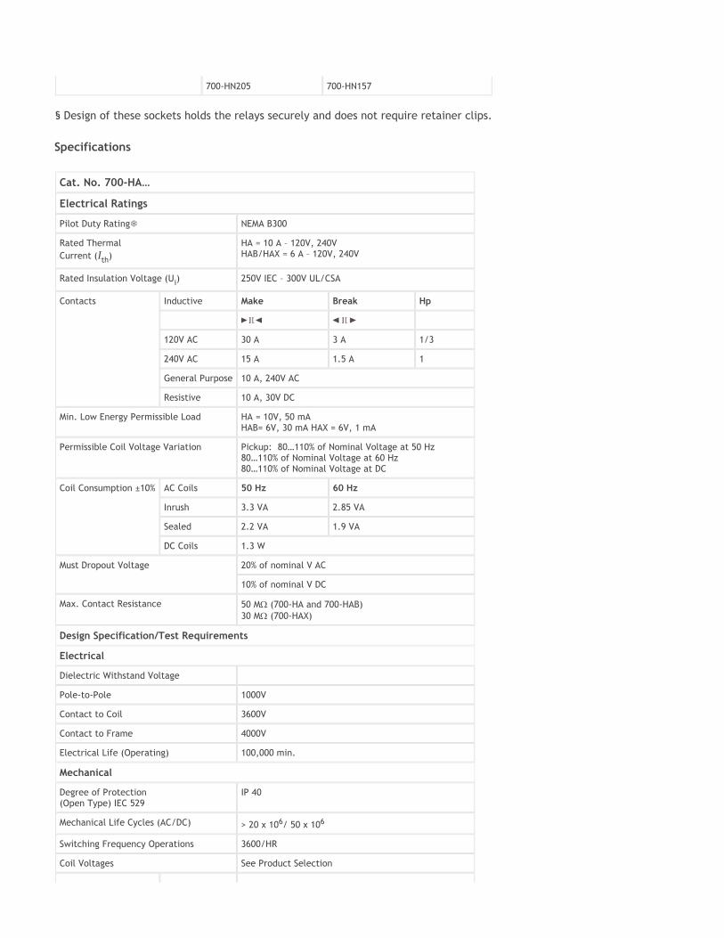
Specifications
700-HN205 700-HN157
§ Design of these sockets holds the relays securely and does not require retainer clips.
Cat. No. 700-HA…
Electrical Ratings
Pilot Duty Rating NEMA B300
Rated Thermal Current (Ith)
HA = 10 A – 120V, 240V HAB/HAX = 6 A – 120V, 240V
Rated Insulation Voltage (Ui) 250V IEC – 300V UL/CSA
Contacts Inductive Make Break Hp
120V AC 30 A 3 A 1/3
240V AC 15 A 1.5 A 1
General Purpose 10 A, 240V AC
Resistive 10 A, 30V DC
Min. Low Energy Permissible Load HA = 10V, 50 mA HAB= 6V, 30 mA HAX = 6V, 1 mA
Permissible Coil Voltage Variation Pickup: 80…110% of Nominal Voltage at 50 Hz 80…110% of Nominal Voltage at 60 Hz 80…110% of Nominal Voltage at DC
Coil Consumption ±10% AC Coils 50 Hz 60 Hz
Inrush 3.3 VA 2.85 VA
Sealed 2.2 VA 1.9 VA
DC Coils 1.3 W
Must Dropout Voltage 20% of nominal V AC
10% of nominal V DC
Max. Contact Resistance 50 MΩ (700-HA and 700-HAB) 30 MΩ (700-HAX)
Design Specification/Test Requirements
Electrical
Dielectric Withstand Voltage
Pole-to-Pole 1000V
Contact to Coil 3600V
Contact to Frame 4000V
Electrical Life (Operating) 100,000 min.
Mechanical
Degree of Protection (Open Type) IEC 529
IP 40
Mechanical Life Cycles (AC/DC) > 20 x 106/ 50 x 106
Switching Frequency Operations 3600/HR
Coil Voltages See Product Selection

700-HA Relay Performance Graphs
Operating Time Max. Pickup 10 ms
Max. Dropout 10 ms
Maximum Operating Rate 4 Ops/s
Vibration Endurance 5 G
Operational 2.5 G
Shock Endurance 50 G
Operational 9 G
Environmental
Temperature Operating AC/DC –40…+70 °C
Storage AC/DC –40…+100 °C
Altitude 2000 m (6560 ft)
Construction
Insulating Material Molded High Dielectric Material
Enclosure Transparent Dust Cover
Contact Material 700-HA: 10 A– AgNi
700-HAB: 6 A–Bifurcated AgNi
700-HAX: 6 A–Bifurcated/Gold Plating AgNi
Terminal Markings on Socket In accordance with EN50 0005
Sockets 8-Pin Socket — 700-HN100, -HN125, -HN204 11-Pin Socket — 700-HN101, -HN126, -HN205
Certifications CE, cULus listed, IMQ, RINA, ABS
Performance Data – See page Important 2, Industrial Controls Catalog. NEMA Rating Chart is on page 19 of publication 700-SG003B-EN-P.
Contact life vs. AC1 load at 1,800 cycles/h
Breaking capacity for DC1 load at 1,800 cycles/h.
Load reduction factor vs. cos φ
A = load applied to 1 contact B = load applied to 2 contacts in series C = load applied to 3 contacts in series
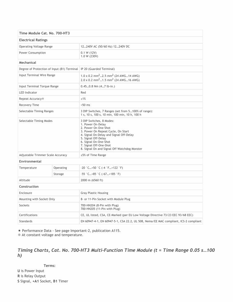
Timing Charts, Cat. No. 700-HT3 Multi-Function Time Module (t = Time Range 0.05 s…100 h) Terms: U is Power Input R is Relay Output S Signal, +A1 Socket, B1 Timer
Time Module Cat. No. 700-HT3
Electrical Ratings
Operating Voltage Range 12…240V AC (50/60 Hz) 12…240V DC
Power Consumption 0.1 W (12V) 1.0 W (230V)
Mechanical
Degree of Protection of Input (B1) Terminal IP 20 (Guarded Terminal)
Input Terminal Wire Range 1.0 x 0.2 mm2…2.5 mm2 (24 AWG…14 AWG)
2.0 x 0.2 mm2…1.5 mm2 (24 AWG…16 AWG)
Input Terminal Torque Range 0.45…0.8 Nm (4…7 lb-in.)
LED Indicator Red
Repeat Accuracy ±1%
Recovery Time <50 ms
Selectable Timing Ranges 3 DIP Switches, 7 Ranges (set from 5…100% of range): 1 s, 10 s, 100 s, 10 min, 100 min, 10 h, 100 h
Selectable Timing Modes 3 DIP Switches, 8 Modes: 1. Power On–Delay 2. Power On One-Shot 3. Power On Repeat Cycle, On Start 4. Signal On-Delay and Signal Off-Delay 5. Signal Off-Delay 6. Signal On-One-Shot 7. Signal Off-One-Shot 8. Signal On and Signal Off Watchdog Monster
Adjustable Trimmer Scale Accuracy ±5% of Time Range
Environmental
Temperature Operating –20 °C…+50 °C (–4 °F…+122 °F)
Storage –55 °C…+85 °C (–67…+185 °F)
Altitude 2000 m (6560 ft)
Construction
Enclosure Gray Plastic Housing
Mounting with Socket Only 8- or 11-Pin Socket with Module Plug
Sockets 700-HN204 (8-Pin with Plug) 700-HN205 (11-Pin with Plug)
Certifications CE, UL listed, CSA, CE-Marked (per EU Low Voltage Directive 73/23 EEC 93/68 EEC)
Standards EN 60947-4-1, EN 60947-5-1, CSA 22.2, UL 508, Nema/EE MAC compliant, ICS-2 compliant
Performance Data - See page Important-2, publication A115. At constant voltage and temperature.

t is the resulting Time Delay (Red LED) 1. Power On-Delay Apply power (U) to timer. Relay contacts (R) change state after time delay (t) is complete. Contacts return to their shelf state when power is removed. Terminal B1 is not used in this mode.
2. Power On One-Shot Apply power (U) to timer. Relay contacts (R) change state immediately and the time delay begins. When the time delay (t) is complete, contacts return to their shelf state. Contacts return to their shelf state when power is removed. Terminal B1 is not used in this mode.
3. Power On Repeat Cycle, On Start Apply power (U) to timer. Relay contacts (R) change state immediately and the time delay (t) begins. When the time delay is complete, the contacts return to their shelf state for time delay (t) (time on = time off). This cycle will repeat until the power is removed. Terminal B1 is not used in this mode.
4. Signal On-Delay and Signal Off-Delay
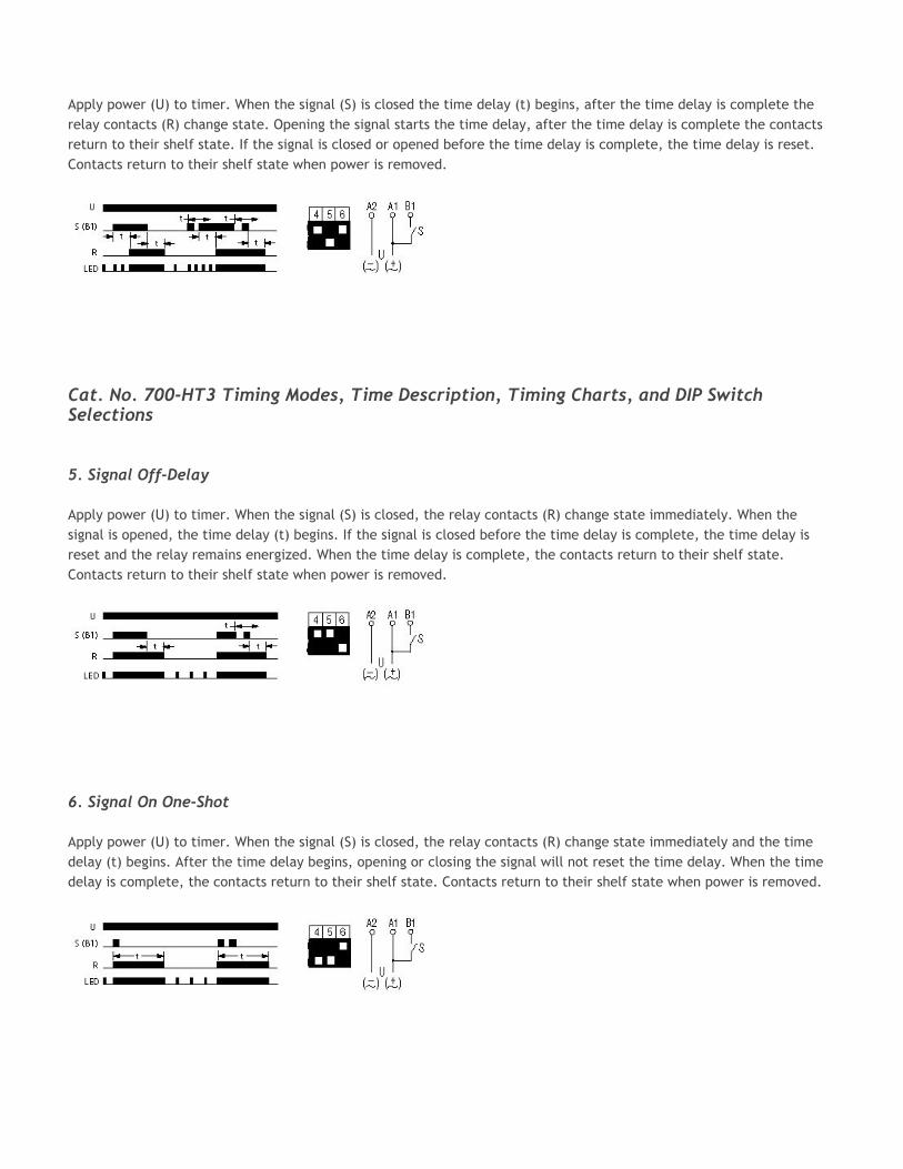
Apply power (U) to timer. When the signal (S) is closed the time delay (t) begins, after the time delay is complete the relay contacts (R) change state. Opening the signal starts the time delay, after the time delay is complete the contacts return to their shelf state. If the signal is closed or opened before the time delay is complete, the time delay is reset. Contacts return to their shelf state when power is removed.
Cat. No. 700-HT3 Timing Modes, Time Description, Timing Charts, and DIP Switch Selections 5. Signal Off-Delay Apply power (U) to timer. When the signal (S) is closed, the relay contacts (R) change state immediately. When the signal is opened, the time delay (t) begins. If the signal is closed before the time delay is complete, the time delay is reset and the relay remains energized. When the time delay is complete, the contacts return to their shelf state. Contacts return to their shelf state when power is removed.
6. Signal On One-Shot Apply power (U) to timer. When the signal (S) is closed, the relay contacts (R) change state immediately and the time delay (t) begins. After the time delay begins, opening or closing the signal will not reset the time delay. When the time delay is complete, the contacts return to their shelf state. Contacts return to their shelf state when power is removed.
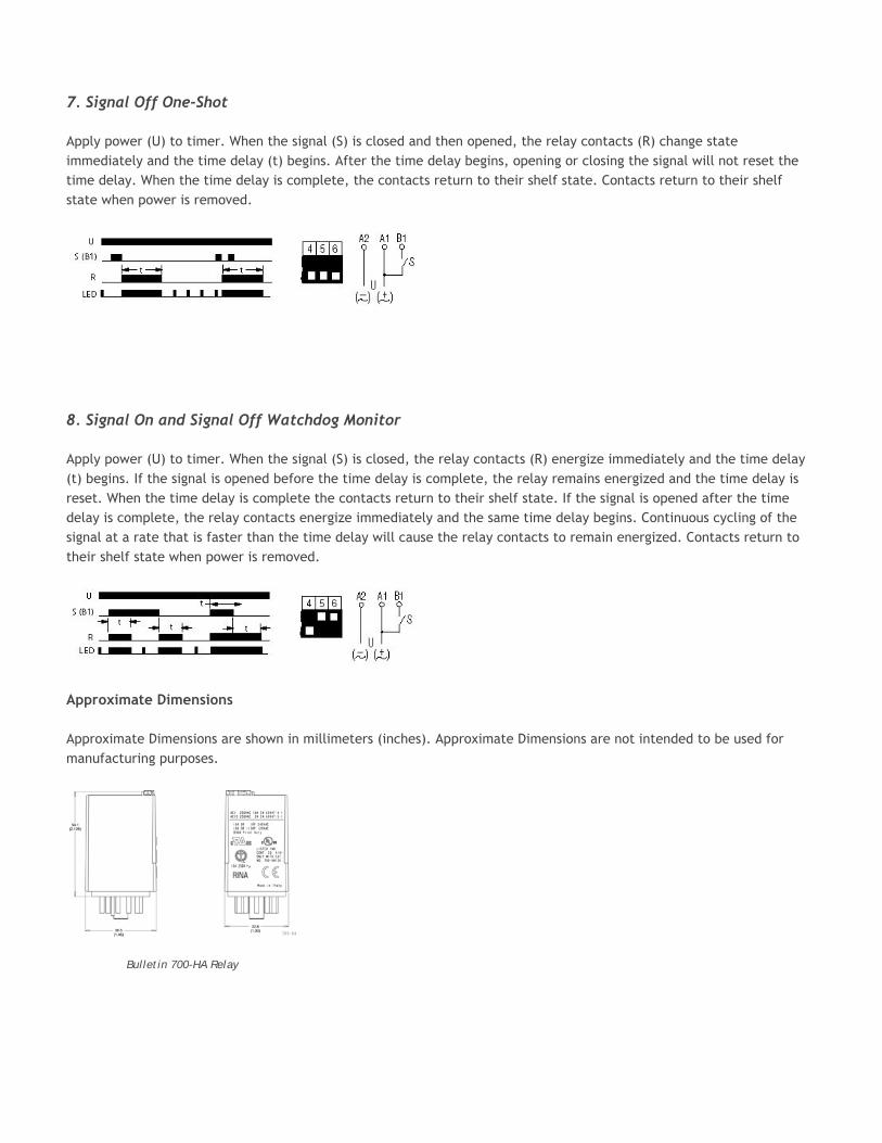
7. Signal Off One-Shot Apply power (U) to timer. When the signal (S) is closed and then opened, the relay contacts (R) change state immediately and the time delay (t) begins. After the time delay begins, opening or closing the signal will not reset the time delay. When the time delay is complete, the contacts return to their shelf state. Contacts return to their shelf state when power is removed.
8. Signal On and Signal Off Watchdog Monitor Apply power (U) to timer. When the signal (S) is closed, the relay contacts (R) energize immediately and the time delay (t) begins. If the signal is opened before the time delay is complete, the relay remains energized and the time delay is reset. When the time delay is complete the contacts return to their shelf state. If the signal is opened after the time delay is complete, the relay contacts energize immediately and the same time delay begins. Continuous cycling of the signal at a rate that is faster than the time delay will cause the relay contacts to remain energized. Contacts return to their shelf state when power is removed.
Approximate Dimensions Approximate Dimensions are shown in millimeters (inches). Approximate Dimensions are not intended to be used for manufacturing purposes.
Bulletin 700-HA Relay
Approximate Dimensions are shown in millimeters (inches). Approximate Dimensions are not intended to be used for manufacturing purposes.
Wire Size: 2 x 2.5 mm2
Single Wire – Up to #12 AWG Double Wire – 2 x 2.5 mm2 (#2–14 AWG… #2–20 AWG)
(Either Solid or Stranded) Strip Length: 9 mm (3/8 in) – Torque: 0.8 Nm (7 lb•in)
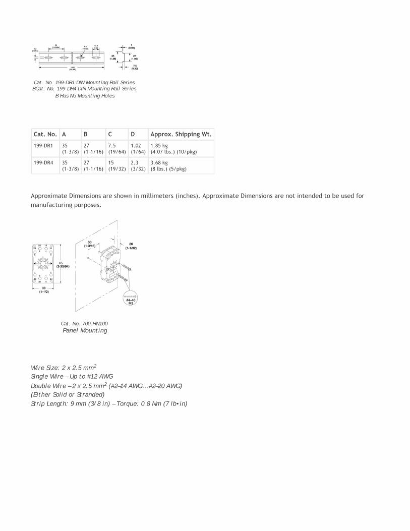
Cat. No. 199-DR1 DIN Mounting Rail Series BCat. No. 199-DR4 DIN Mounting Rail Series
B Has No Mounting Holes
Cat. No. A B C D Approx. Shipping Wt.
199-DR1 35 (1-3/8)
27 (1-1/16)
7.5 (19/64)
1.02 (1/64)
1.85 kg (4.07 lbs.) (10/pkg)
199-DR4 35 (1-3/8)
27 (1-1/16)
15 (19/32)
2.3 (3/32)
3.68 kg (8 lbs.) (5/pkg)
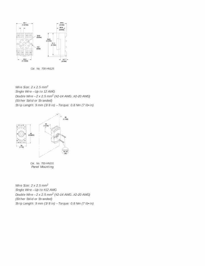
Cat. No. 700-HN100 Panel Mounting
Wire Size: 2 x 2.5 mm2
Single Wire – Up to 12 AWG Double Wire – 2 x 2.5 mm2 (#2–14 AWG…#2–20 AWG)
(Either Solid or Stranded) Strip Length: 9 mm (3/8 in) – Torque: 0.8 Nm (7 lb•in)
Wire Size: 2 x 2.5 mm2
Single Wire – Up to #12 AWG Double Wire – 2 x 2.5 mm2 (#2–14 AWG…#2–20 AWG)
(Either Solid or Stranded) Strip Length: 9 mm (3/8 in) – Torque: 0.8 Nm (7 lb•in)
Cat. No. 700-HN125
Cat. No. 700-HN101 Panel Mounting
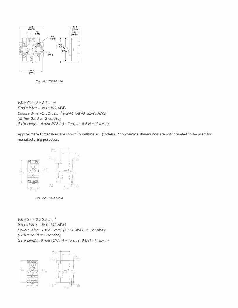
Wire Size: 2 x 2.5 mm2
Single Wire – Up to #12 AWG Double Wire – 2 x 2.5 mm2 (#2–#14 AWG…#2–20 AWG)
(Either Solid or Stranded) Strip Length: 9 mm (3/8 in) – Torque: 0.8 Nm (7 lb•in) Approximate Dimensions are shown in millimeters (inches). Approximate Dimensions are not intended to be used for manufacturing purposes.
Wire Size: 2 x 2.5 mm2
Single Wire – Up to #12 AWG Double Wire – 2 x 2.5 mm2 (#2–14 AWG… #2–20 AWG)
(Either Solid or Stranded) Strip Length: 9 mm (3/8 in) – Torque: 0.8 Nm (7 lb•in)
Cat. No. 700-HN126
Cat. No. 700-HN204
Locations|Contact|Sitemap|Legal Notices Copyright © 2006 Rockwell Automation, Inc. All Rights Reserved.
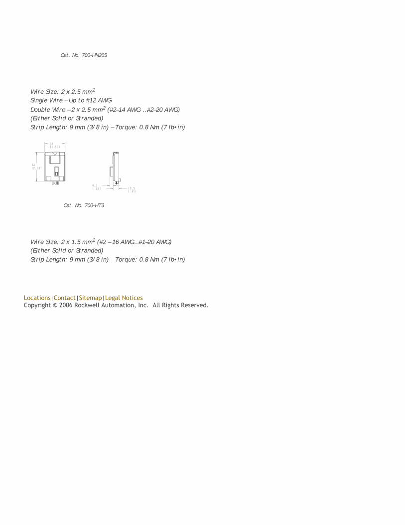
Wire Size: 2 x 2.5 mm2
Single Wire – Up to #12 AWG Double Wire – 2 x 2.5 mm2 (#2–14 AWG …#2–20 AWG)
(Either Solid or Stranded) Strip Length: 9 mm (3/8 in) – Torque: 0.8 Nm (7 lb•in)
Wire Size: 2 x 1.5 mm2 (#2 – 16 AWG…#1–20 AWG)
(Either Solid or Stranded) Strip Length: 9 mm (3/8 in) – Torque: 0.8 Nm (7 lb•in)
Cat. No. 700-HN205
Cat. No. 700-HT3


![· Caffè Latte [Hot/lce] ñ7x3yî- Café au Lait [Hot/lce] Cappuccino Espresso Hot Chocolate 650 1,000 650 700 700 700 700 700 700 700 700 700 To the guests who have some allergy](https://img.pdfslide.us/doc/110x75/5c674b4309d3f226588ba938/-caffe-latte-hotlce-n7x3yi-cafe-au-lait-hotlce-cappuccino-espresso.jpg)