Embed Size (px)
Citation preview
MINI-Fireworks building instruction May 2015
www.pcm.at 1
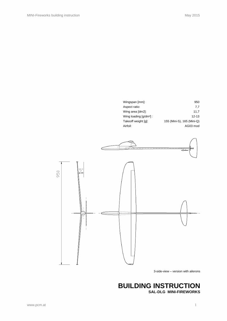
Wingspan [mm]: 950 Aspect ratio: 7,7
Wing area [dm2]: 11,7
Wing loading [g/dm²] : 12-13
Takeoff weight [g]: 155 (Mini-S), 165 (Mini-Q)
Airfoil: AG03 mod
3-side-view – version with ailerons
BUILDING INSTRUCTION SAL-DLG MINI-FIREWORKS
MINI-Fireworks building instruction May 2015
www.pcm.at 2
CONTENTS DATA 1. Kit – contents 2. What else do you need? 3. Electronic equipment 4. Settings for the first flight ASSEMBLING THE MODEL 5. General information on DLG-models 6. Fuselage - structure 7. Stabilizer 8. Fuselage - installation of electronic components 9. Controlling of the ailerons 10. Installation of antenna OTHER 11. Check list before starting
3 3 3 4
5 5 7
13 14 15
16
MINI-Fireworks building instruction May 2015
www.pcm.at 3
DATA
1. Kit – contents
Fuselage (canopy, middle part, boom) Wing Elevator (Balsa) Rudder (Balsa) Radioboard Balsa part for mounting elevator, 1 piece Carbon lever for controlling elevator, 1 piece Carbon lever for controlling rudder, 1 piece (Mini-S) Carbon levers for controlling ailerons, 2 pieces (Mini-Q) Carbon push rods for controlling ailerons, 2 pieces (Mini-Q) Steel wire for controlling elevator (and rudder, Mini-S) Steel wire for springs, 1 piece (Mini-Q), 2 pieces (Mini-S) Screws for fixing wing, 2 pieces Carbon roving, glass fibre Building instruction
2. What else do you need:
Iron-on covering film (for coating balsa stabs), f.e. Oracover, or special varnish to fill pores Epoxy-glue (for example UHU 300 endfest or Pattex Stabilit, no fast hardening epoxy resin) Super glue, thin Maybe cotton flocks (to thicken epoxy-glue) Electrical equipment (On/Off-switch, cables, plug, ...) Electronic equipment Steel wire, shrinking tube...
3. Electronic equipment
Servos elevator/rudder/aileron
- Dymond D-47 Similar: - Futaba FS31
- Modell Expert X31
Accumulators: - GP NiMH Accu 35AAAH, weight/cell 6g (1,2 Volt 0,35 Ah 1/2AAA)
Receiver: - MZK Sexta Mini - Jeti Rex 540MPD
MINI-Fireworks building instruction May 2015
www.pcm.at 4
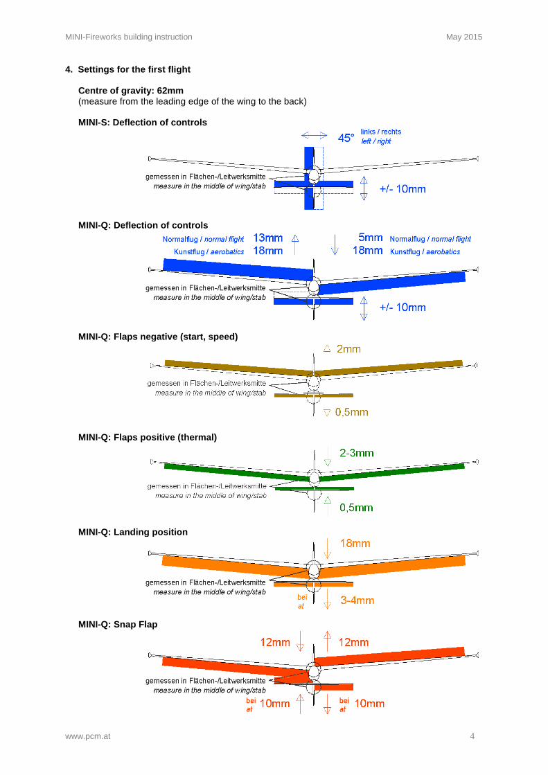
4. Settings for the first flight
Centre of gravity: 62mm (measure from the leading edge of the wing to the back)
MINI-S: Deflection of controls
MINI-Q: Deflection of controls
MINI-Q: Flaps negative (start, speed)
MINI-Q: Flaps positive (thermal)
MINI-Q: Landing position
MINI-Q: Snap Flap
MINI-Fireworks building instruction May 2015
www.pcm.at 5
ASSEMBLING THE MODEL 5. General information on DLG-models
DLG-models - such as MINI-Fireworks - are constructed strong enough to withstand the demands of starting, flying and landing and at the same time light enough to achieve the least possible flying weight. Each part is dimensioned to its possible minimum and produced using lightest and fewest material. In order to continue this concept, please account the following when you assemble the model: - Always use glue sparingly. Grind all gluing spots thoroughly, before you apply the glue. - Electronic components should be placed as far as possible to the front, as you normally
need additional lead in the nose of the fuselage to achieve the necessary centre of gravity. - For the same reason try to save weight especially when you finish and mount the
stabilizer. - If you don’t have any experience in working with resin or if you prefer an easier method, you
can combine the carbon rovings and glass fibre with super glue: Put some drops of super glue on the rovings or the fibre, spread and press it with a (rustling) plastic bag. You will also save one or the other gram with this method.
As both versions (Mini-S controlled by elevator/rudder and Mini-Q controlled by elevator/aileron) are described in the following, you can skip the parts of the instruction, that don’t apply to your model.
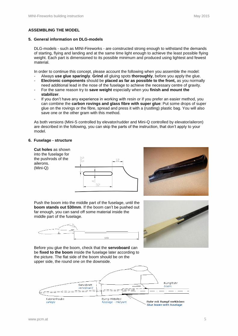
6. Fuselage - structure
Cut holes as shown into the fuselage for the pushrods of the ailerons. (Mini-Q)
Push the boom into the middle part of the fuselage, until the boom stands out 530mm. If the boom can’t be pushed out far enough, you can sand off some material inside the middle part of the fuselage.
Before you glue the boom, check that the servoboard can be fixed to the boom inside the fuselage later according to the picture. The flat side of the boom should be on the upper side, the round one on the downside.
MINI-Fireworks building instruction May 2015
www.pcm.at 6
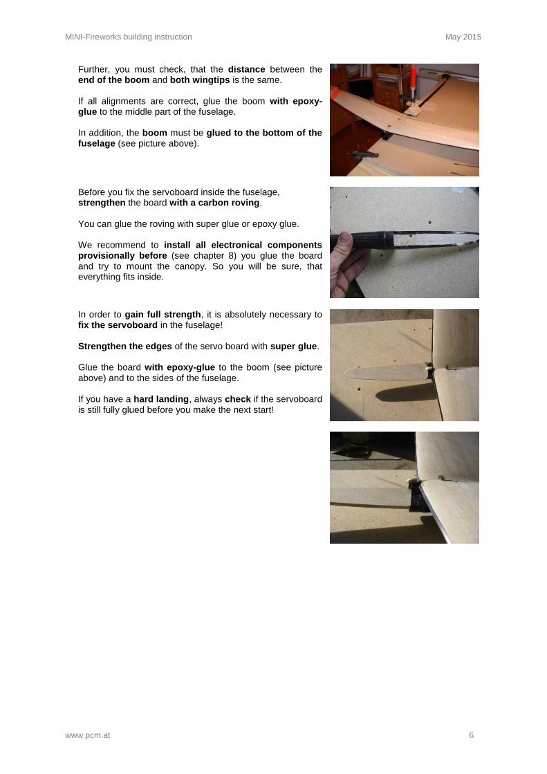
Further, you must check, that the distance between the end of the boom and both wingtips is the same. If all alignments are correct, glue the boom with epoxy-glue to the middle part of the fuselage. In addition, the boom must be glued to the bottom of the fuselage (see picture above).
Before you fix the servoboard inside the fuselage, strengthen the board with a carbon roving. You can glue the roving with super glue or epoxy glue. We recommend to install all electronical components provisionally before (see chapter 8) you glue the board and try to mount the canopy. So you will be sure, that everything fits inside.
In order to gain full strength, it is absolutely necessary to fix the servoboard in the fuselage! Strengthen the edges of the servo board with super glue. Glue the board with epoxy-glue to the boom (see picture above) and to the sides of the fuselage. If you have a hard landing, always check if the servoboard is still fully glued before you make the next start!
MINI-Fireworks building instruction May 2015
www.pcm.at 7
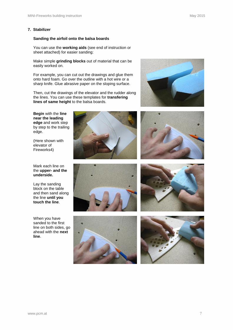
7. Stabilizer
Sanding the airfoil onto the balsa boards You can use the working aids (see end of instruction or sheet attached) for easier sanding:
Make simple grinding blocks out of material that can be easily worked on. For example, you can cut out the drawings and glue them onto hard foam. Go over the outline with a hot wire or a sharp knife. Glue abrasive paper on the sloping surface. Then, cut the drawings of the elevator and the rudder along the lines. You can use these templates for transfering lines of same height to the balsa boards.
Begin with the line near the leading edge and work step by step to the trailing edge. (Here shown with elevator of Fireworks4)
Mark each line on the upper- and the underside. Lay the sanding block on the table and then sand along the line until you touch the line.
When you have sanded to the first line on both sides, go ahead with the next line.
MINI-Fireworks building instruction May 2015
www.pcm.at 8
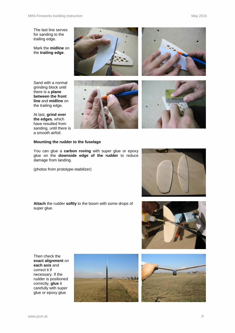
The last line serves for sanding to the trailing edge. Mark the midline on the trailing edge.
Sand with a normal grinding block until there is a plane between the front line and midline on the trailing edge. At last, grind over the edges, which have resulted from sanding, until there is a smooth airfoil.
Mounting the rudder to the fuselage
You can glue a carbon roving with super glue or epoxy glue on the downside edge of the rudder to reduce damage from landing. (photos from prototype-stabilizer)
Attach the rudder softly to the boom with some drops of super glue.
Then check the exact alignment on each axis and correct it if necessary. If the rudder is positioned correctly, glue it carefully with super glue or epoxy glue.
MINI-Fireworks building instruction May 2015
www.pcm.at 9
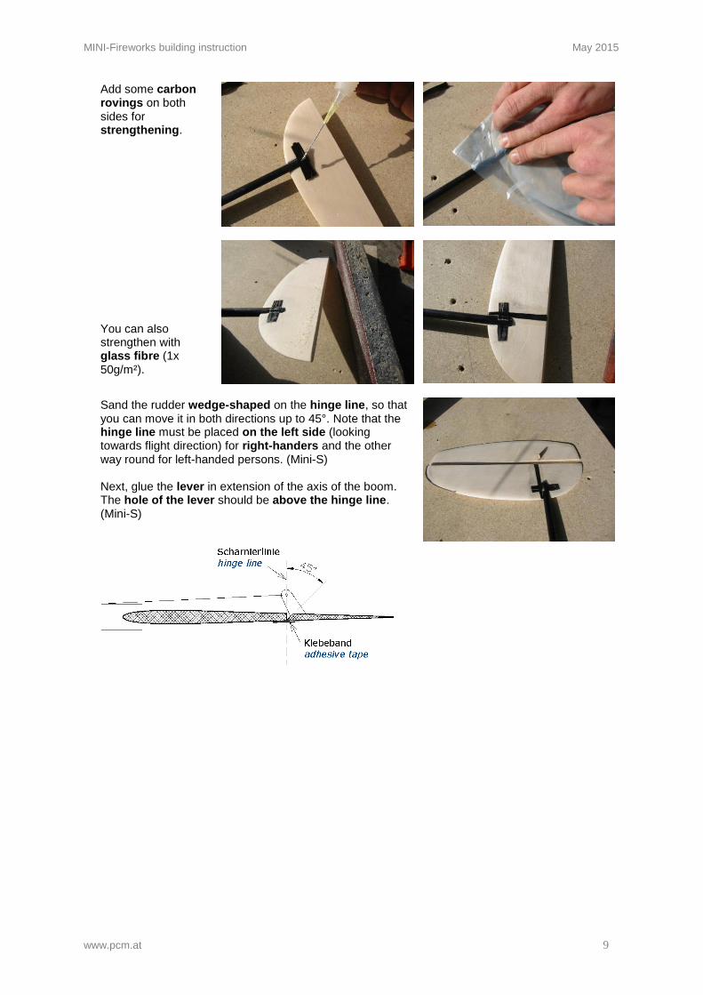
Add some carbon rovings on both sides for strengthening.
You can also strengthen with glass fibre (1x 50g/m²).
Sand the rudder wedge-shaped on the hinge line, so that you can move it in both directions up to 45°. Note that the hinge line must be placed on the left side (looking towards flight direction) for right-handers and the other way round for left-handed persons. (Mini-S) Next, glue the lever in extension of the axis of the boom. The hole of the lever should be above the hinge line. (Mini-S)
MINI-Fireworks building instruction May 2015
www.pcm.at 10
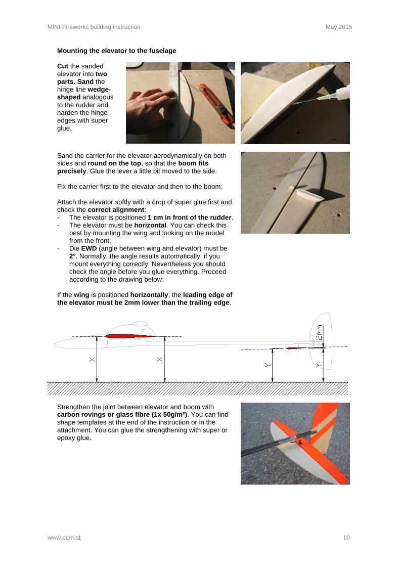
Mounting the elevator to the fuselage
Cut the sanded elevator into two parts. Sand the hinge line wedge-shaped analogous to the rudder and harden the hinge edges with super glue.
Sand the carrier for the elevator aerodynamically on both sides and round on the top, so that the boom fits precisely. Glue the lever a little bit moved to the side. Fix the carrier first to the elevator and then to the boom: Attach the elevator softly with a drop of super glue first and check the correct alignment: - The elevator is positioned 1 cm in front of the rudder. - The elevator must be horizontal. You can check this
best by mounting the wing and looking on the model from the front.
- Die EWD (angle between wing and elevator) must be 2°. Normally, the angle results automatically, if you mount everything correctly. Nevertheless you should check the angle before you glue everything. Proceed according to the drawing below:
If the wing is positioned horizontally, the leading edge of the elevator must be 2mm lower than the trailing edge.
Strengthen the joint between elevator and boom with carbon rovings or glass fibre (1x 50g/m²). You can find shape templates at the end of the instruction or in the attachment. You can glue the strengthening with super or epoxy glue.
MINI-Fireworks building instruction May 2015
www.pcm.at 11
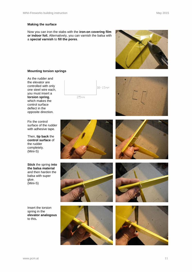
Making the surface
Now you can iron the stabs with the iron-on covering film or indoor foil. Alternatively, you can varnish the balsa with a special varnish to fill the pores.
Mounting torsion springs
As the rudder and the elevator are controlled with only one steel wire each, you must insert a torsion spring, which makes the control surface deflect in the opposite direction.
Fix the control surface of the rudder with adhesive tape. Then, tip back the control surface of the rudder completely. (Mini-S)
Stick the spring into the balsa material and then harden the balsa with super glue. (Mini-S)
Insert the torsion spring in the elevator analogous to this.
MINI-Fireworks building instruction May 2015
www.pcm.at 12
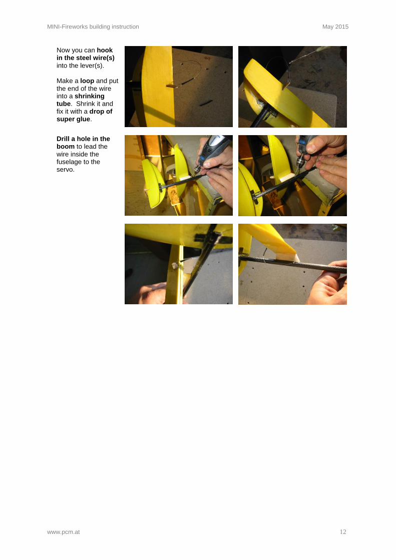
Now you can hook in the steel wire(s) into the lever(s). Make a loop and put the end of the wire into a shrinking tube. Shrink it and fix it with a drop of super glue.
Drill a hole in the boom to lead the wire inside the fuselage to the servo.
MINI-Fireworks building instruction May 2015
www.pcm.at 13
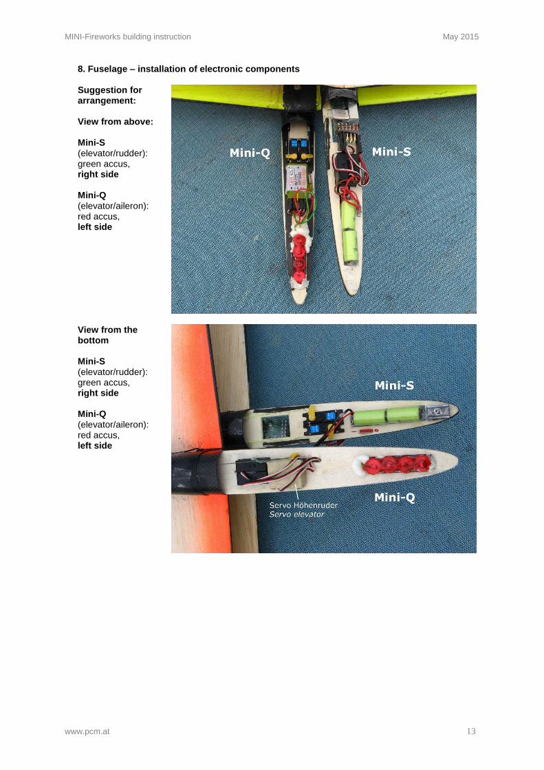
8. Fuselage – installation of electronic components
Suggestion for arrangement: View from above: Mini-S (elevator/rudder): green accus, right side Mini-Q (elevator/aileron): red accus, left side
View from the bottom Mini-S (elevator/rudder): green accus, right side Mini-Q (elevator/aileron): red accus, left side
MINI-Fireworks building instruction May 2015
www.pcm.at 14
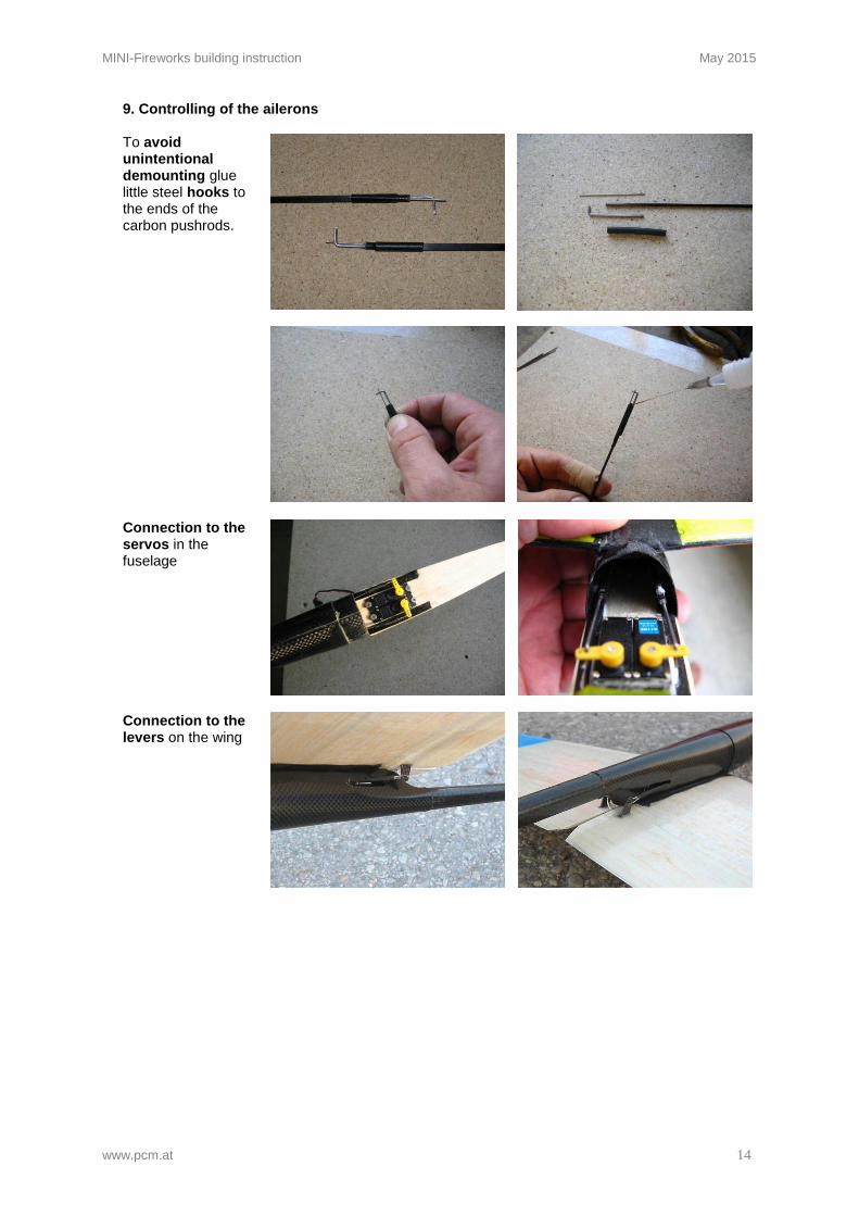
9. Controlling of the ailerons
To avoid unintentional demounting glue little steel hooks to the ends of the carbon pushrods.
Connection to the servos in the fuselage
Connection to the levers on the wing
MINI-Fireworks building instruction May 2015
www.pcm.at 15
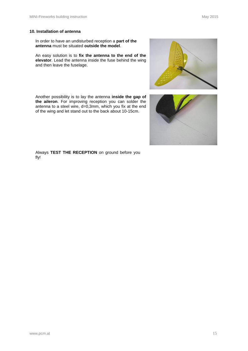
10. Installation of antenna In order to have an undisturbed reception a part of the antenna must be situated outside the model. An easy solution is to fix the antenna to the end of the elevator. Lead the antenna inside the fuse behind the wing and then leave the fuselage.
Another possibility is to lay the antenna inside the gap of the aileron. For improving reception you can solder the antenna to a steel wire, d=0,3mm, which you fix at the end of the wing and let stand out to the back about 10-15cm.
Always TEST THE RECEPTION on ground before you fly!

MINI-Fireworks building instruction May 2015
www.pcm.at 16
OTHER
11. Check list before starting:
1. Check centre of gravity 2. Check control surfaces:
Do control surfaces move in the correct direction? Check the greatest swings
3. Check reception: Leave the antenna inside the radio control and go away from the glider up to a distance of about 60m. The control surfaces should not tremble.