Embed Size (px)
Citation preview
Erwin XL Ultralight Electro - building Instruction August 2018
www.pcm.at 1
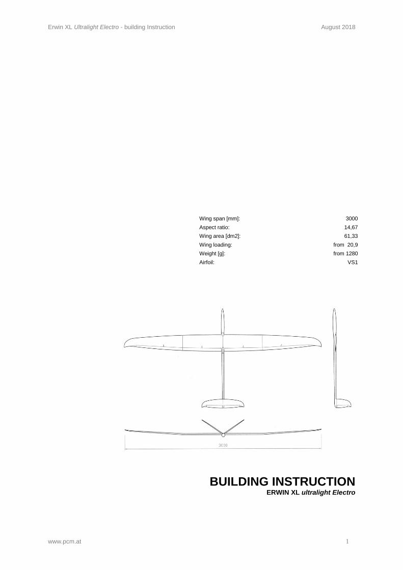
Wing span [mm]: 3000 Aspect ratio: 14,67 Wing area [dm2]: 61,33 Wing loading: from 20,9 Weight [g]: from 1280 Airfoil: VS1
BUILDING INSTRUCTION ERWIN XL ultralight Electro
Erwin XL Ultralight Electro - building Instruction August 2018
www.pcm.at 2
CONTENTS DATA 1. Kit – Contents 2. What else do you need? 3. Electronic equipment – electric drive 4. Settings for the first flight ASSEMBLING THE MODEL 5. V-tail 6. Gluing of fuselage 7. Electronic components in fuselage (electric drive) 8. Wing 9. Installation of antenna BEFORE THE FIRST FLIGHT 10. Ballast system 11. Fixing of the wing 12. Check list before starting
3 3 4 5
6 7 8
12 14
15 15 15
Erwin XL Ultralight Electro - building Instruction August 2018
www.pcm.at 3
DATA
1. Kit – Contents
Fuselage, in two parts, incl. canopy and cover for end of fuselage, 1 piece Wing, in two parts V-Tail Covers for servos on wing, 4 pieces Levers for rudders, 4 pieces Installation frame for engine Fuselage board with 2 sideboards Cover for opening for receiver Tube for 2,4 GHz-antennas Plugs and frames for connection of wing and fuselage, 4 pieces each Screws, 2 pieces, for fixing the V-tail Covers for servos on V-tail Plug for V-tail, 1 piece Levers, 2 pieces Connectros / ballast (more ballast available on demand):
Segler / Glider Elektro
Normal (Slope) 2x Kohlestab / carbon rod 2x Stahl kurz / steel short 1x Stahl lang / steel long (auf Anfrage / on demand)
2x Kohlestab / carbon rod
Medium
1x Kohlestab / carbon rod 2x Stahl kurz / steel short
1x Kohlestab / carbon rod 1x Stahl kurz / steel short
Ultralight
1x Kohlerohr / carbon pipe 1x Kohlerohr + Stahl innen /carbon pipe + steel core 1x Stahl kurz / steel short
1x Kohlerohr / carbon pipe
Building instruction (please download from our homepage)
2. What else do you need:
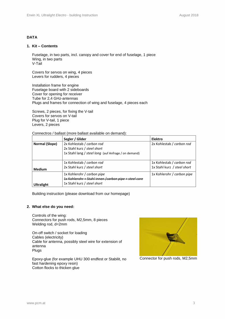
Controls of the wing: Connectors for push rods, M2,5mm, 8 pieces Welding rod, d=2mm On-off switch / socket for loading Cables (electricity) Cable for antenna, possibly steel wire for extension of antenna Plugs Epoxy-glue (for example UHU 300 endfest or Stabilit, no fast hardening epoxy resin) Cotton flocks to thicken glue
Connector for push rods, M2,5mm
Erwin XL Ultralight Electro - building Instruction August 2018
www.pcm.at 4
3. Electronical equipment
Servos for the wing
Dymond D60
Hyperion Atlas HP DS09SCD
Servos for the V-tail
Dymond D60
Receiver: 2,4GHz: all (antennas must be led outside the fuselage)
35 MHz: Graupner DS19 Simprop Scan 7
Electric drive Variante 1 Flying weight: Engine: Controller: Accumulator: Propeller: Spinner: Price (app.): Variante 2 Flying weight: Engine: Controller: Accumulator: Propeller: Spinner: Price (app.): Variante 3 Flying weight: Engine: Controller: Accumulator: Propeller: Spinner: Price (app.): Logger / Limiter:
strong (calculated app. 2,6kg thrust), high quality, heavy (391g) app. 1510g Kira 400 - 39, with gear 5,2:1 (110g+60g) Jeti spin 44 (36g) Wellpower DS Lipo 3S 2200mAh (185g) Aeronaut 13/8 D=30mm EUR 340,- (Inkl. 20%Vat.) strong (calculated app. 2,4kg thrust), cheaper, heavy (374g) app. 1490g Typhoon EDF-2W-20, with gear 5,2:1 (93g+60g) Jeti spin 44 (36g) Wellpower DS Lipo 3S 2200mAh (185g) Aeronaut 14/8 D=30mm EUR 270,- (Inkl. 20% Vat.) weak (calculated app. 2,0kg thrust), light, low-priced (166g) app. 1280g Hyperion GS 2218-12 (83,5g) Dualsky XC-45 Lite (12,5g) Wellpower DS Lipo 3S 1300mAh (70g) Aeronaut 11/7 D=30 EUR 125,- (Inkl. 20% Vat.) Unilog 2 for use in competition The stronger the drive, the more camber
Erwin XL Ultralight Electro - building Instruction August 2018
www.pcm.at 5
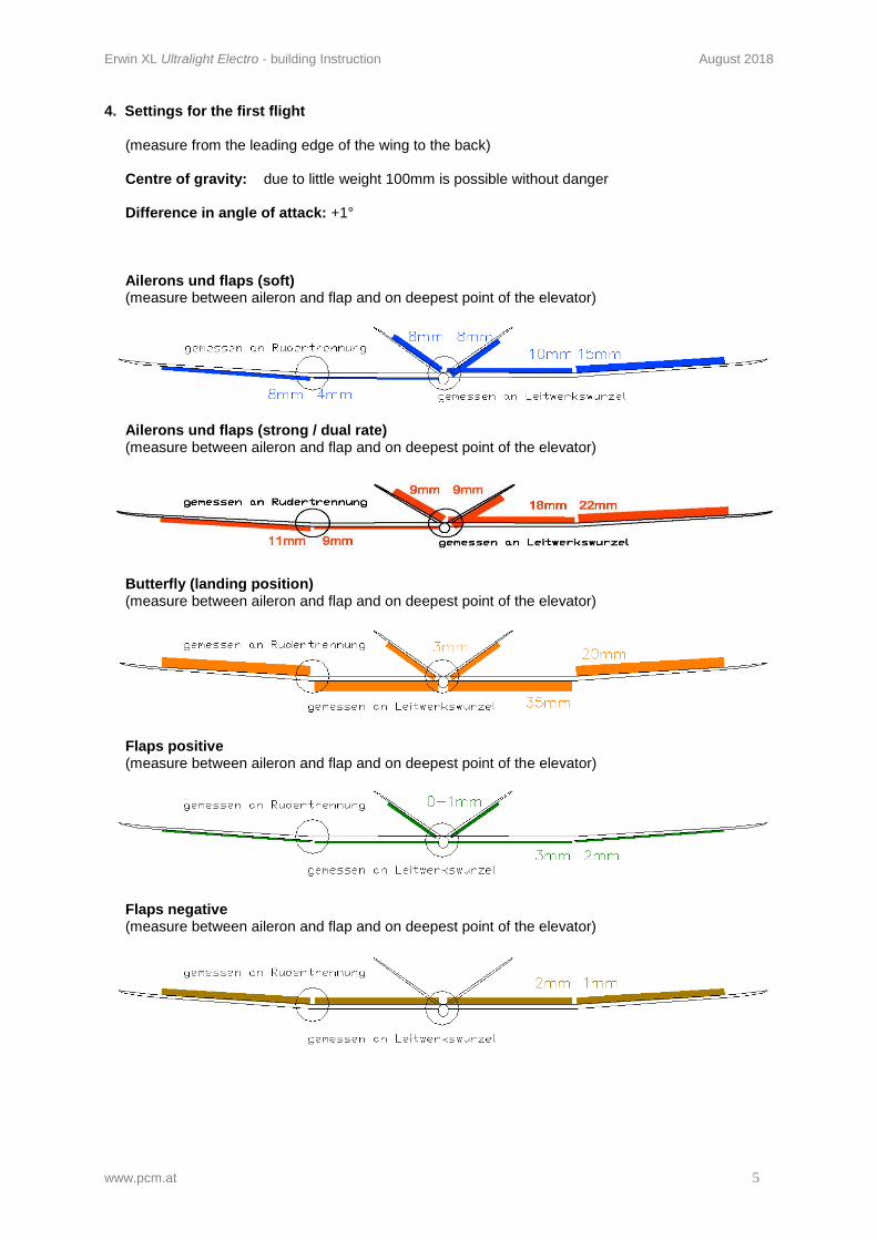
4. Settings for the first flight
(measure from the leading edge of the wing to the back) Centre of gravity: due to little weight 100mm is possible without danger Difference in angle of attack: +1°
Ailerons und flaps (soft) (measure between aileron and flap and on deepest point of the elevator)
Ailerons und flaps (strong / dual rate) (measure between aileron and flap and on deepest point of the elevator)
Butterfly (landing position) (measure between aileron and flap and on deepest point of the elevator)
Flaps positive (measure between aileron and flap and on deepest point of the elevator)
Flaps negative (measure between aileron and flap and on deepest point of the elevator)
Erwin XL Ultralight Electro - building Instruction August 2018
www.pcm.at 6
ASSEMBLING THE MODEL
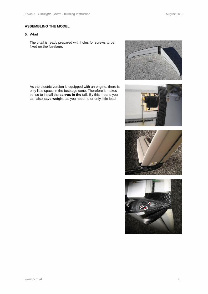
5. V-tail
The v-tail is ready prepared with holes for screws to be fixed on the fuselage. As the electric version is equipped with an engine, there is only little space in the fuselage cone. Therefore it makes sense to install the servos in the tail. By this means you can also save weight, as you need no or only little lead.
Erwin XL Ultralight Electro - building Instruction August 2018
www.pcm.at 7
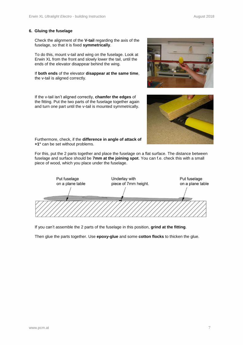
6. Gluing the fuselage
Check the alignment of the V-tail regarding the axis of the fuselage, so that it is fixed symmetrically. To do this, mount v-tail and wing on the fuselage. Look at Erwin XL from the front and slowly lower the tail, until the ends of the elevator disappear behind the wing. If both ends of the elevator disappear at the same time, the v-tail is aligned correctly.
If the v-tail isn’t aligned correctly, chamfer the edges of the fitting. Put the two parts of the fuselage together again and turn one part until the v-tail is mounted symmetrically. Furthermore, check, if the difference in angle of attack of +1° can be set without problems.
For this, put the 2 parts together and place the fuselage on a flat surface. The distance between fuselage and surface should be 7mm at the joining spot. You can f.e. check this with a small piece of wood, which you place under the fuselage.
If you can’t assemble the 2 parts of the fuselage in this position, grind at the fitting.
Then glue the parts together. Use epoxy-glue and some cotton flocks to thicken the glue.
Erwin XL Ultralight Electro - building Instruction August 2018
www.pcm.at 8
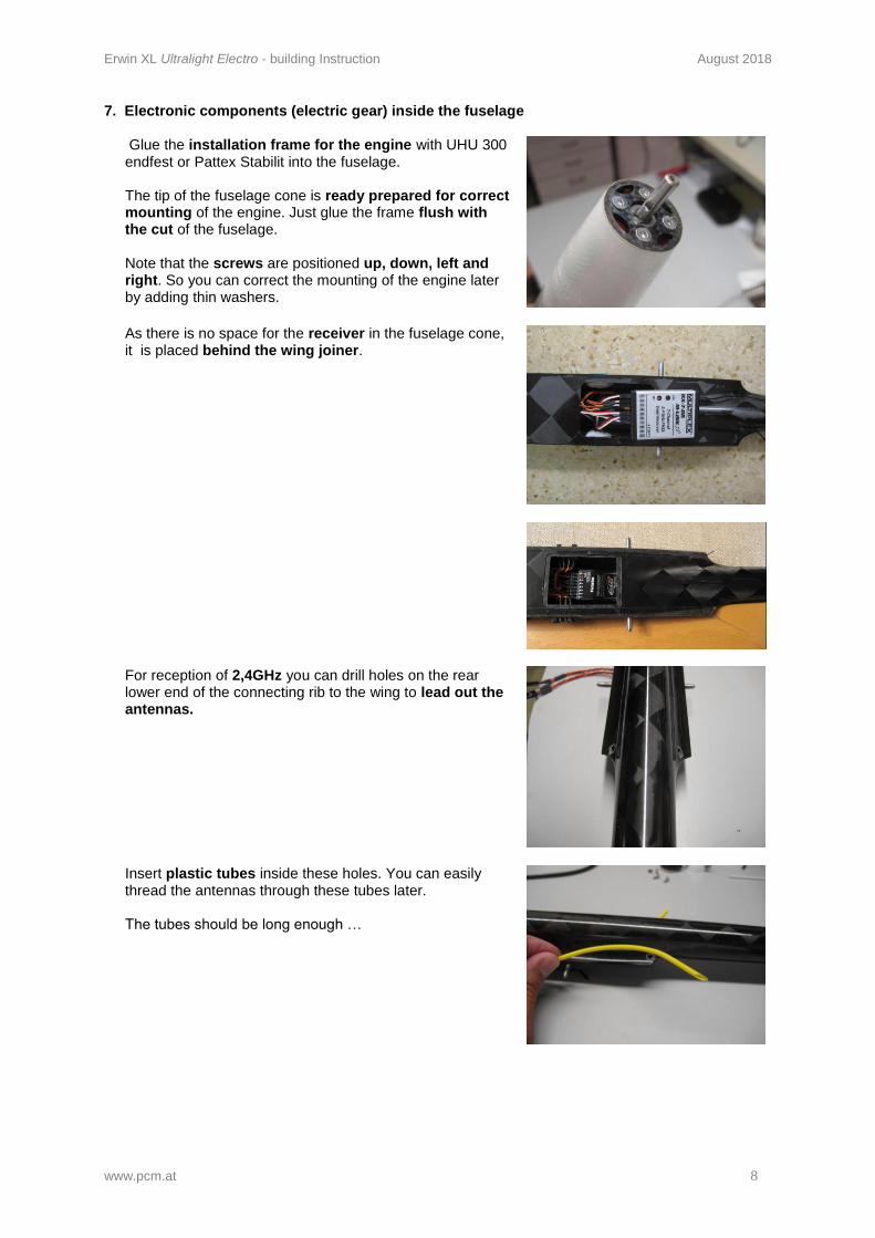
7. Electronic components (electric gear) inside the fuselage
Glue the installation frame for the engine with UHU 300 endfest or Pattex Stabilit into the fuselage. The tip of the fuselage cone is ready prepared for correct mounting of the engine. Just glue the frame flush with the cut of the fuselage. Note that the screws are positioned up, down, left and right. So you can correct the mounting of the engine later by adding thin washers.
As there is no space for the receiver in the fuselage cone, it is placed behind the wing joiner.
For reception of 2,4GHz you can drill holes on the rear lower end of the connecting rib to the wing to lead out the antennas.
Insert plastic tubes inside these holes. You can easily thread the antennas through these tubes later. The tubes should be long enough …
Erwin XL Ultralight Electro - building Instruction August 2018
www.pcm.at 9
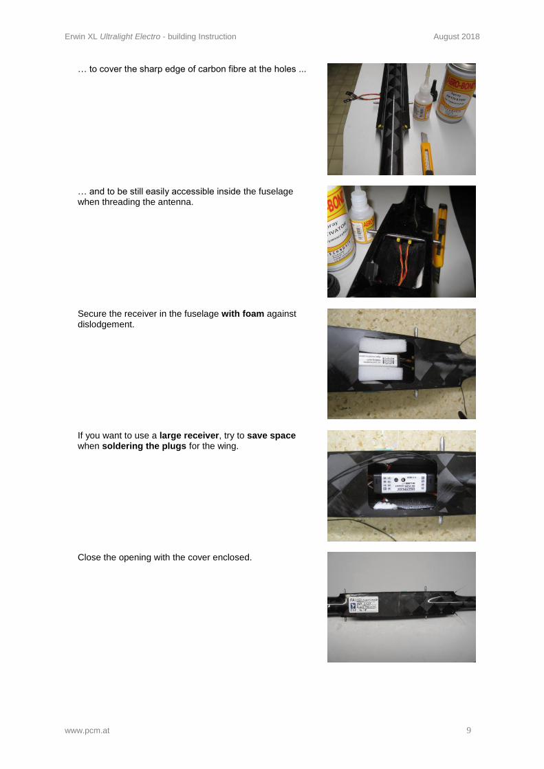
… to cover the sharp edge of carbon fibre at the holes ...
… and to be still easily accessible inside the fuselage when threading the antenna.
Secure the receiver in the fuselage with foam against dislodgement.
If you want to use a large receiver, try to save space when soldering the plugs for the wing.
Close the opening with the cover enclosed.
Erwin XL Ultralight Electro - building Instruction August 2018
www.pcm.at 10
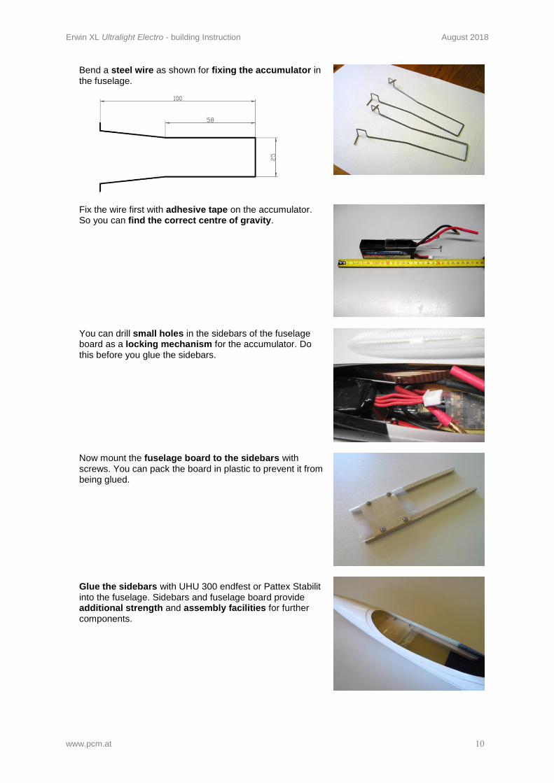
Bend a steel wire as shown for fixing the accumulator in the fuselage.
Fix the wire first with adhesive tape on the accumulator. So you can find the correct centre of gravity.
You can drill small holes in the sidebars of the fuselage board as a locking mechanism for the accumulator. Do this before you glue the sidebars.
Now mount the fuselage board to the sidebars with screws. You can pack the board in plastic to prevent it from being glued. Glue the sidebars with UHU 300 endfest or Pattex Stabilit into the fuselage. Sidebars and fuselage board provide additional strength and assembly facilities for further components.
Erwin XL Ultralight Electro - building Instruction August 2018
www.pcm.at 11
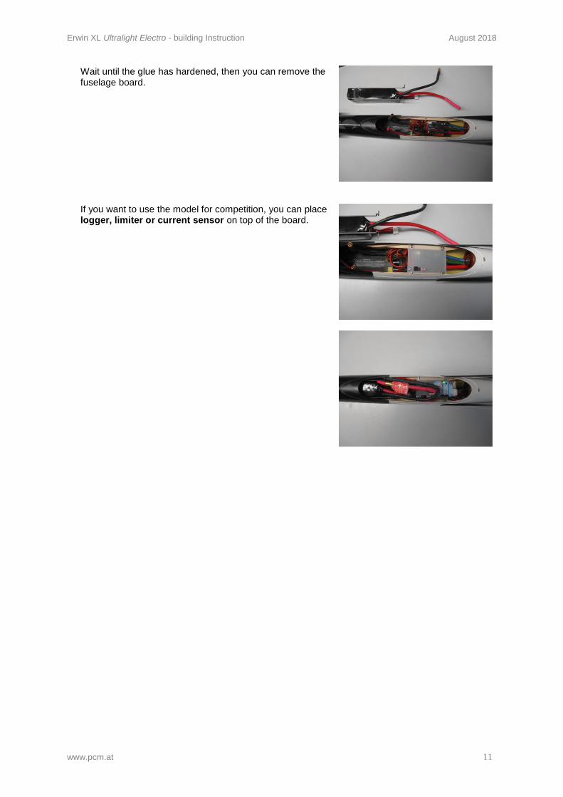
Wait until the glue has hardened, then you can remove the fuselage board.
If you want to use the model for competition, you can place logger, limiter or current sensor on top of the board.
Erwin XL Ultralight Electro - building Instruction August 2018
www.pcm.at 12
8. Wing
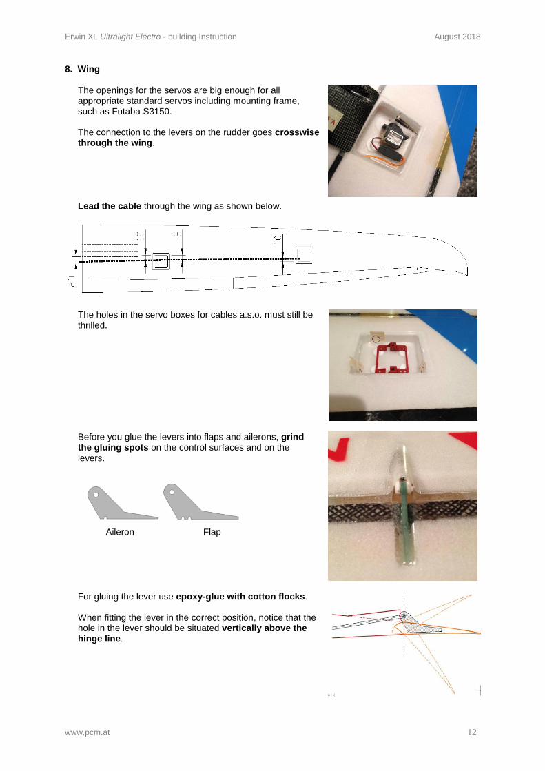
The openings for the servos are big enough for all appropriate standard servos including mounting frame, such as Futaba S3150. The connection to the levers on the rudder goes crosswise through the wing. Lead the cable through the wing as shown below.
The holes in the servo boxes for cables a.s.o. must still be thrilled.
Before you glue the levers into flaps and ailerons, grind the gluing spots on the control surfaces and on the levers.
Aileron Flap
For gluing the lever use epoxy-glue with cotton flocks. When fitting the lever in the correct position, notice that the hole in the lever should be situated vertically above the hinge line.
Erwin XL Ultralight Electro - building Instruction August 2018
www.pcm.at 13
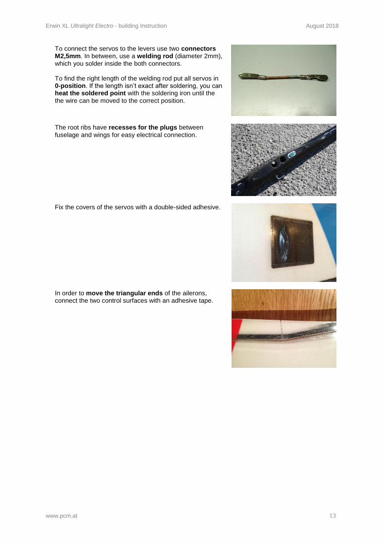
To connect the servos to the levers use two connectors M2,5mm. In between, use a welding rod (diameter 2mm), which you solder inside the both connectors. To find the right length of the welding rod put all servos in 0-position. If the length isn’t exact after soldering, you can heat the soldered point with the soldering iron until the the wire can be moved to the correct position.
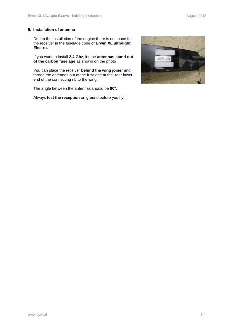
The root ribs have recesses for the plugs between fuselage and wings for easy electrical connection.
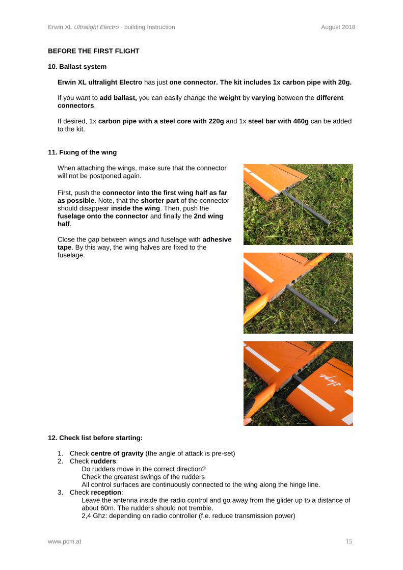
Fix the covers of the servos with a double-sided adhesive.
In order to move the triangular ends of the ailerons, connect the two control surfaces with an adhesive tape.
Erwin XL Ultralight Electro - building Instruction August 2018
www.pcm.at 14
9. Installation of antenna
Due to the installation of the engine there is no space for the receiver in the fuselage cone of Erwin XL ultralight Electro. If you want to install 2,4 Ghz, let the antennas stand out of the carbon fuselage as shown on the photo You can place the receiver behind the wing joiner and thread the antennas out of the fuselage at the rear lower end of the connecting rib to the wing. The angle between the antennas should be 90°. Always test the reception on ground before you fly!
Erwin XL Ultralight Electro - building Instruction August 2018
www.pcm.at 15
BEFORE THE FIRST FLIGHT
10. Ballast system
Erwin XL ultralight Electro has just one connector. The kit includes 1x carbon pipe with 20g. If you want to add ballast, you can easily change the weight by varying between the different connectors. If desired, 1x carbon pipe with a steel core with 220g and 1x steel bar with 460g can be added to the kit.
11. Fixing of the wing
When attaching the wings, make sure that the connector will not be postponed again.
First, push the connector into the first wing half as far as possible. Note, that the shorter part of the connector should disappear inside the wing. Then, push the fuselage onto the connector and finally the 2nd wing half. Close the gap between wings and fuselage with adhesive tape. By this way, the wing halves are fixed to the fuselage.
12. Check list before starting: 1. Check centre of gravity (the angle of attack is pre-set) 2. Check rudders:
Do rudders move in the correct direction? Check the greatest swings of the rudders All control surfaces are continuously connected to the wing along the hinge line.
3. Check reception: Leave the antenna inside the radio control and go away from the glider up to a distance of about 60m. The rudders should not tremble. 2,4 Ghz: depending on radio controller (f.e. reduce transmission power)