Embed Size (px)
Citation preview

Building for High Wind Resistance in Light-Frame Wood Construction

Building for High Wind Resistance in Light-Frame Wood ConstructionIntroductionDesigning a structure to withstand the devastating
forces of tornados and hurricanes is one of the greatest
challenges a builder can face. There’s a common
myth that all tornados are so strong that structural
failure is imminent, no matter how well a building
is constructed. The fact is, weaker tornados rated as
EF-0, EF-1 and EF-2 by the National Weather Service
statistically comprise 95 percent of all tornados. A
home that is carefully constructed, in accordance with
current building codes, can withstand these smaller,
less violent storms.
Stronger tornados rating EF-3, EF-4 and EF-5 are
much less common. While it’s more difficult for homes
to survive these storms, good design details can make
a difference, particularly when the structure is located
along the outer reaches of the area influenced by the
vortex of the storm.
The design and construction recommendations in
this guide from APA contribute to improved overall
performance in the structural shell and focus on
good connection details to tie together exterior walls,
roofs, and floors. Some of these design recommendations
exceed the minimum code requirements and typical APA
recommendations. Whether caused by a tornado or
hurricane, high wind forces travel through the load
path of a structure. Good connections that tie the floor,
walls, and roof together provide continuity in the load
path and more reliable building performance.
2 | FORM NO. M310 ■ © 2011 APA – THE ENGINEERED WOOD ASSOCIATION ■ WWW.APAWOOD.ORG

Click on circled letters for enlarged
view of detail.
A Nail roof sheathing with 8d ring shank (or deformed shank) (0.131" x 2-1/2") nailsat 4 inches on center along the ends of the sheathing and 6 inches on center alongintermediate framing.
B Tie gable end walls back to the structure. One of the weakest links in residential structures during high wind events is the connection between the gable-end and the wall below.
C Sheath gable end walls with wood structural panels, such as plywood or oriented strand board (OSB). In the 2011 tornados, gable end wall failures were frequently observed when non-structural sheathing was used.
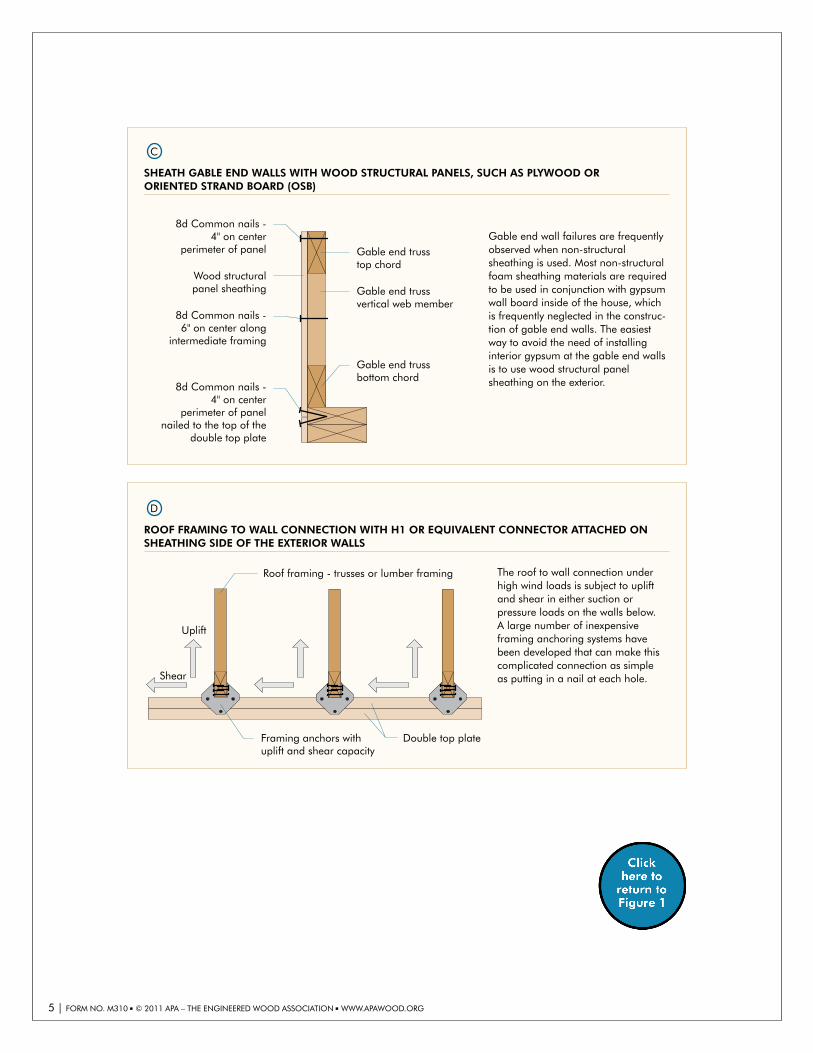
D For the roof framing to wall connection, use an H1 or equivalent connector, attached on the exterior (sheathing side) of the exterior walls. The roof-to-wall connection under high wind loads is subject to both uplift and shear due to positive or negative wind pressure on the walls below.
E Nail upper story sheathing and lower story sheathing into common wood structural panel Rim Board®. The most effective way to provide lateral and uplift load continuity is to attach adjacent wall sheathing panels to one another over common framing.
F Nail wall sheathing with 8d common (0.131" x 2-1/2") nails at 4 inches on center at end and edges of wood structural panels and 6 inches on center in the intermediate framing. This enhanced nailing will improve the resistance of the wall sheathing panels to negative wind pressure. Staples offer less resistance to blow-off than nails and so a greater number of them are required to achieve the same level of resistance.
G Continuously sheath all walls with wood structural panels including areas around openings for windows and doors.
H Extend wood structural panel sheathing to lapthe sill plate. The connection of the wall sheathing panel to the sill plate is important because thisis where uplift forces are transferred into the sill plate and into the foundation through theanchor bolts.
I Space 1/2" anchor bolts 32 inches to 48 inches on center with 0.229" x 3" x 3" square plate washers with slotted holes.
FIGURE 1
TIPS FOR IMPROVING TORNADO OR HURRICANE RESISTANCE OF LIGHT-FRAME WOOD CONSTRUCTION
3 | FORM NO. M310 ■ © 2011 APA – THE ENGINEERED WOOD ASSOCIATION ■ WWW.APAWOOD.ORG

(2) 10d nails(typical)
Roof Trusses
Blocking between truss bottom chords
Gable end truss top chord
Gable end truss bottom chord
2" x 4" x 8'continuous lateralbrace @ 6'on center
Tension-tie strap, attach with (8) 10d Common nails, each end of strap
B
TIE GABLE END WALLS BACK TO THE STRUCTURE
One of the weakest links in residential structures during high wind events is the connection between the gable end and the wall below. The prescriptive codes provide no guidance on how to properly attach these two important elements and failures at this joint are, unfortunately, quite common. Construction details that have been developed to properly secure and tie back a gable end may be used. Also common in high wind areas is to eliminate the gable through the use of hip roofs or, if the gable is an architec-tural necessity, use balloon framing. (Detail courtesy of Standard for Hurricane Resistant Residential Construc-tion, SSTD 10-93 Section 306.4.2.)
8d Common nails -6" on center alongintermediate framing
8d Common nails -4" on center at panel ends
Roof sheathing Roof framing
A
NAIL ROOF SHEATHING WITH 8D RING SHANK (0.131" X 2-1/2") OR DEFORMED SHANK NAILS AT 4"ON CENTER AT PANEL ENDS AND EDGES AND 6" ON CENTER IN THE INTERMEDIATE FRAMING
This installation will greatly increase the wind resistance of the roof sheathing panels.
4 | FORM NO. M310 ■ © 2011 APA – THE ENGINEERED WOOD ASSOCIATION ■ WWW.APAWOOD.ORG
8d Common nails -4" on center
perimeter of panel
8d Common nails -6" on center along
intermediate framing
Gable end trusstop chord
Gable end trussvertical web member
Gable end trussbottom chord
Wood structuralpanel sheathing
C
SHEATH GABLE END WALLS WITH WOOD STRUCTURAL PANELS, SUCH AS PLYWOOD ORORIENTED STRAND BOARD (OSB)
Gable end wall failures are frequently observed when non-structural sheathing is used. Most non-structural foam sheathing materials are required to be used in conjunction with gypsum wall board inside of the house, which is frequently neglected in the construc-tion of gable end walls. The easiest way to avoid the need of installing interior gypsum at the gable end walls is to use wood structural panel sheathing on the exterior.8d Common nails -
4" on centerperimeter of panel
nailed to the top of the double top plate
Roof framing - trusses or lumber framing
Double top plateFraming anchors withuplift and shear capacity
Uplift
Shear
D
ROOF FRAMING TO WALL CONNECTION WITH H1 OR EQUIVALENT CONNECTOR ATTACHED ONSHEATHING SIDE OF THE EXTERIOR WALLS
The roof to wall connection under high wind loads is subject to uplift and shear in either suction or pressure loads on the walls below.A large number of inexpensive framing anchoring systems have been developed that can make this complicated connection as simple as putting in a nail at each hole.
5 | FORM NO. M310 ■ © 2011 APA – THE ENGINEERED WOOD ASSOCIATION ■ WWW.APAWOOD.ORG

8d Common nails at 4" on center at panel ends and edges
8d Common nails at 6" on center at intermediate supports
F
NAIL WALL SHEATHING WITH 8D COMMON (0.131" X 2-1/2") NAILS AT 4" ON CENTER INTHE BOUNDARY OF WOOD STRUCTURAL PANEL WALL SHEATHING AND 6" ON CENTER INTHE INTERMEDIATE STUDS
This installation will increase the wind resistance of the wall sheathing panels, as compared to the minimum nailing requirements specified inthe code.
Wood structuralpanel Rim Board
Sheathing from upper and lower stories nailed to common wood
structural panel Rim Board ties building together making it
more resistant to wind damage
Other connections are not shown
for clarity
E
NAIL OFF UPPER STORY AND LOWER STORY SHEATHING INTO COMMON WOODSTRUCTURAL PANEL RIM BOARD
The most effective way to provide lateral and in some cases uplift load continuity is to attach adjacent wood structural panel wall sheathing to one another over common framing. The common availability of long length Rim Board can be used as this common framing member to ensure shear and uplift continuity, which eliminates the need for horizontal blocking. Being at least 9-1/2" in depth, the Rim Board makes an excellent “target” for mating adjacent panels. The problems associated with mating two panels over the edge of a 2x member while maintaining a 1/8" spacing between panels, a 3/8" edge distance from the nail to the edge of the panel, and still being able to hit the framing behind the panel with the nail are greatly reduced. For use around windows and doors or as an alternative to this detail, metal strap anchors designed for such applications may be used. For designed applications, additional information is available in APA Data File: Shear Transfer at Engineered Wood Floors, Form Y250.
6 | FORM NO. M310 ■ © 2011 APA – THE ENGINEERED WOOD ASSOCIATION ■ WWW.APAWOOD.ORG

Even with the loss of wall covering andbuilding paper, continuous plywood
and OSB sheathing offers additional protection.
Building paperBuilding paper
G
SHEATH ALL WALLS WITH WOOD STRUCTURAL PANELS
A solid plywood or OSB box is created when the roof and walls, properly attached, are completely sheathed. All of the wall needs protection from high wind and wind driven debris, not just the bracing panels at corners and at intervals along the length of a wall. The minute the siding is blown off the wall, the remainder of the wall left behind must be able to protect the contents of the structure from the wind and rain by itself. Buildings that are continuously sheathed with wood structural panels have an additional layer of protection if siding is lost or brick veneer collapses during high wind events. In addition, if there is not structural panel sheathing attached to the sill plate in the area of the anchor bolt, its hold down capacity is not transferred to the structure above.
Attaching the continuous sheathing
directly to the sill plate helps tie the
structure above to the foundation below.
Other connections are not shown
for clarity
I-joist
Rim Board
Wall sheathing
H
EXTEND WOOD STRUCTURAL PANEL SHEATHING AT BOTTOM WALL TO SILL PLATE INTERSECTION
The connection of the wall sheathing panel to sill plateis extremely important because this is the connectionby which the hold down capacity of the sill plate anchor bolting is distributed into the structure above. At this location, the panel can overlap the sill plate by the full 1-1/2" of the sill plate depth. It is wise to use all of this depth as it permits the use of nail-to-edge distancesof up to 3/4", yielding the maximum possible uplift capacity of the nailed joint. See Detail F for nailing recommendations.
7 | FORM NO. M310 ■ © 2011 APA – THE ENGINEERED WOOD ASSOCIATION ■ WWW.APAWOOD.ORG

I
SPACE 1/2" ANCHOR BOLTS 32" TO 48" ON CENTER WITH 0.229" X 3" X 3" SLOTTED SQUARE PLATEWASHERS AT THE WALL TO SILL PLATE INTERSECTION
A good deal of the damage done to structures due to wind storms is the result of the walls being lifted or pushed off of the foundation. Much of the damage is due to the use of bottom plates nailed to the concrete foundation. These connections perform poorly under high wind loads. Another source of damage is the use of no washers or standard cut washers under the anchor bolt nuts. During high wind uplift, the nuts can pull through the bottom plates and, like the nailed bottom plates, don’t provide the required resistance to keep the walls anchored. The IRC requires a minimum of 1/2" anchor bolt at 72" on center spacing for homes subjected to wind speeds up to 110 mph. However, the use of 1/2" anchor bolts spaced 32" to 48" on center with 0.229" x 3" x 3" slotted square plate washers will greatly improve the resistance to high wind.
1/2" anchor bolts at 32" to 48" on center
tie the structure tothe foundation
Other connections are not shown
for clarity
I-joist
Rim Board
Wall sheathing
Other Considerations:While not falling into the category of relatively simple ways to increase the wind performance of a struc-
ture, there are a number of topics for consideration by the builder/homeowner during the planning or
construction phase of the project. A partial list and brief discussion are as follows:
Protection of large openings - As far as wind damage is concerned, large openings in walls such as pic-
ture windows, sliding glass doors, and garage doors, are extremely vulnerable to damage in high wind
events. Because their areas are large, the total force on the windows/doors is also extremely large. They
also make for big targets for wind-born debris. Breeching of these elements can be especially damaging
to the structure because the size of the opening can lead to pressurization of the entire building, which
can cause failures of other portions of the structure that would be otherwise secure. For these reasons a
builder or homeowner may want to consider windows and doors that are rated for high wind and
impact damage.
Basements and Safe Rooms – The provisions covered in this guide are meant to develop a stronger,
more wind resistant structure. While a stronger structure is certainly safer for the occupants, the home-
owner is wise to consider the use of a full or partial basement or safe room or a combination of both for
life-safety protection.
Hip roofs – While they will not appeal to everyone’s esthetic sense, hip roofs have a long history of supe-
rior performance in high wind events when compared to gable-end styles. The very common problems
associated with gable-end-type failures are virtually eliminated by a properly designed hip roof.
8 | FORM NO. M310 ■ © 2011 APA – THE ENGINEERED WOOD ASSOCIATION ■ WWW.APAWOOD.ORG
Building for High Wind ResistanceWe have field representatives in many major U.S. cities and in Canada
who can help answer questions involving APA trademarked products. For additional assistance in specifying engineered wood products, contact us:
APA HeAdquArters7011 So. 19th St. ■ Tacoma, Washington 98466
(253) 565-6600 ■ Fax: (253) 565-7265
ProduCt suPPort HeLP desk(253) 620-7400
E-mail Address: [email protected]
disCLAimerThe recommendations provided in this publication are intended to provide simplistic tips for improving tornado or hurricane resistance of light-frame wood construction and do not consti-tute an engineering solution that guarantees the safety of the structure so constructed, implicitly or explicitly, by APA. Neither APA, nor its members make any warranty, expressed or implied, or assume any legal liability or responsibility for the use, application of, and/or reference to opinions, findings, conclusions, or recommendations included in this publication. Consult your local jurisdiction or design professional to assure compliance with code, construction, and per-formance requirements. Because APA has no control over quality of workmanship or the condi-tions under which engineered wood products are used, it cannot accept responsibility of product performance or designs as actually constructed
Form No. M310/Issued August 2011