Embed Size (px)
Citation preview

Building a Functional Model
“How will the system work?”
8/1/16 © Copyright 2016 Stevens Institute of Technology, All rights reserved 1

Course Design
8/1/16 2
Deciding What to Build
& Why
Bringing Solutions to Life
Ensuring Systems Work And Are Robust
Managing Evolution…
Deciding What’s Next

Course Design
8/1/16 3
Bringing Solutions to Life
Building a Func,onal Model
Implemen,ng the Func,ons
Specifying Components
Design Review
Class Schedule (1 of 2)
Date Week Topic
Feb 1 1 • Thinking in Terms of Systems
Deciding What to Build and Why
Feb 8 2 • Defining the Problem
Feb 16 3 • Developing a Solution
Feb 22 4 • Formulating a Proposal
Feb 29 5 • Concept Review
Bringing Solutions to Life
Mar 7 6 • Building a Functional Model
Mar 14 7 • Implementing the Functions
Mar 28 8 • Specifying Components
Apr 4 9 • Design Review 8/1/16 © Copyright 2016 Stevens Institute of
Technology, All rights reserved 4
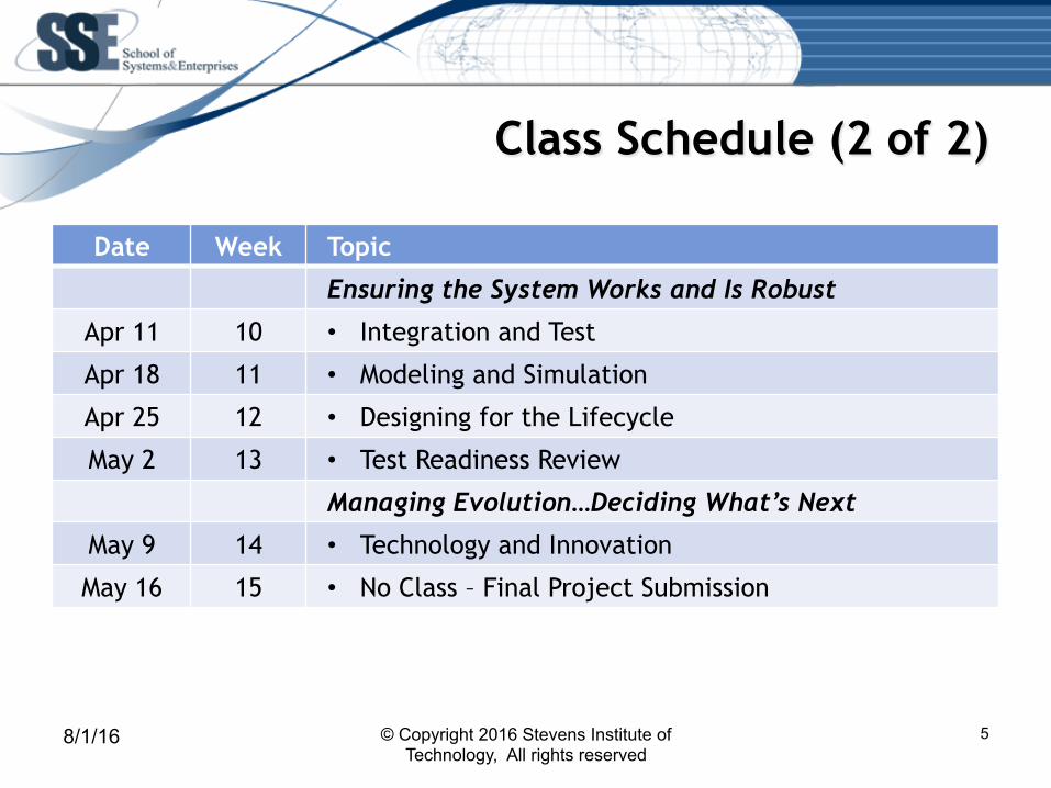
Class Schedule (2 of 2)
Date Week Topic
Ensuring the System Works and Is Robust
Apr 11 10 • Integration and Test
Apr 18 11 • Modeling and Simulation
Apr 25 12 • Designing for the Lifecycle
May 2 13 • Test Readiness Review
Managing Evolution…Deciding What’s Next
May 9 14 • Technology and Innovation
May 16 15 • No Class – Final Project Submission
8/1/16 © Copyright 2016 Stevens Institute of Technology, All rights reserved
5

Deciding How the System Will Work Key Questions:
1. What top-level functions will your system have to perform in order to accomplish it’s mission?
2. How else could you have partitioned the system functionality and why did you choose to partition it the way you did?
3. How will the top-level functions interact with each other and with their external environment?
4. How well will your functional architecture perform and what evidence can you provide to support that assessment?
Part 1: Introduction to System Architecture
8/1/16 7
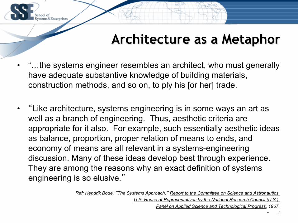
Architecture as a Metaphor
• “…the systems engineer resembles an architect, who must generally have adequate substantive knowledge of building materials, construction methods, and so on, to ply his [or her] trade.
• “Like architecture, systems engineering is in some ways an art as
well as a branch of engineering. Thus, aesthetic criteria are appropriate for it also. For example, such essentially aesthetic ideas as balance, proportion, proper relation of means to ends, and economy of means are all relevant in a systems-engineering discussion. Many of these ideas develop best through experience. They are among the reasons why an exact definition of systems engineering is so elusive.”
Ref: Hendrik Bode, “The Systems Approach,” Report to the Committee on Science and Astronautics,
U.S. House of Representatives by the National Research Council (U.S.), Panel on Applied Science and Technological Progress, 1967.
• :
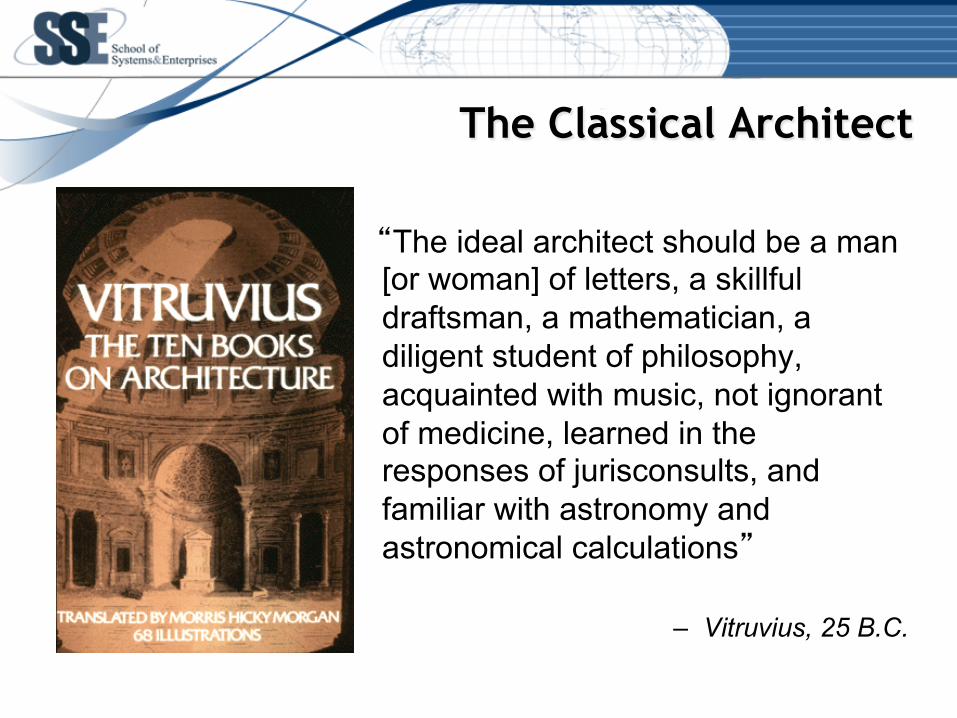
The Classical Architect
“The ideal architect should be a man [or woman] of letters, a skillful draftsman, a mathematician, a diligent student of philosophy, acquainted with music, not ignorant of medicine, learned in the responses of jurisconsults, and familiar with astronomy and astronomical calculations”
– Vitruvius, 25 B.C.

10
Classical Virtues of Architecture
• U"litas – usefulness; appropriate spa,al accommoda,on
• Firmitas – structural soundness; robustness toward change
• Venustas – aesthe,cs and beauty; ability of a form to communicate its func,on and to fit into its environment
Ref: Vitruvius, De Architectura.
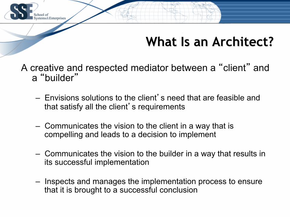
What Is an Architect?
A creative and respected mediator between a “client” and a “builder”
– Envisions solutions to the client’s need that are feasible and
that satisfy all the client’s requirements
– Communicates the vision to the client in a way that is compelling and leads to a decision to implement
– Communicates the vision to the builder in a way that results in its successful implementation
– Inspects and manages the implementation process to ensure that it is brought to a successful conclusion
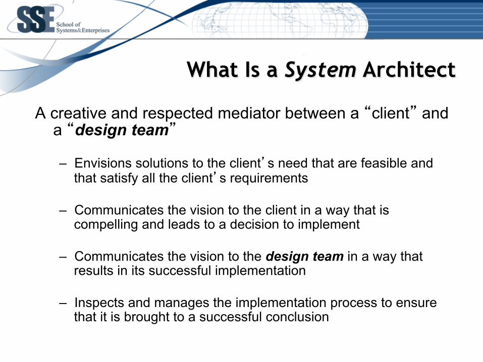
What Is a System Architect
A creative and respected mediator between a “client” and a “design team”
– Envisions solutions to the client’s need that are feasible and
that satisfy all the client’s requirements
– Communicates the vision to the client in a way that is compelling and leads to a decision to implement
– Communicates the vision to the design team in a way that results in its successful implementation
– Inspects and manages the implementation process to ensure that it is brought to a successful conclusion

The Role of a System Architect
Challenges – Determine user needs & how value is created – Effectively manage complexity – Accommodate change – Work within organizational constraints – Balance all of the above
Required Skills
– Technical – To make it work – Communication – To persuade others – Political – To gain access to scarce resources necessary
for the project’s success

14
Perspectives of a Classical Architect
• Objective: Achieve a good “fit” between the form to be designed and its context – Form – that over which we have control – Context – that which puts demands on the form
• Challenge: “We seek to produce harmony between a form we have not yet designed and a context we cannot fully describe.”
• Process: – Define the context as a set of requirements
– Partition the requirements into clusters that are richly connected internally and as independent of each other as possible
– Design a form that meets each cluster of requirements – Integrate the low level forms to produce the desired whole
Ref: C. Alexander, Notes on the Synthesis of Form,
Harvard University Press, 1964.
System Architecture
• System – A set of components that work together to accomplish a common purpose
• System Architecture – The fundamental structure of a system: its elements, the roles they play, and how they are related to each other and to their environment
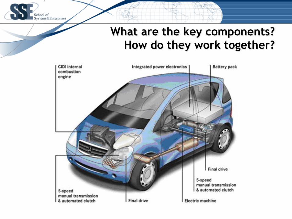
What are the key components? How do they work together?
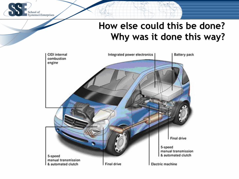
How else could this be done? Why was it done this way?
System Architecture and Design
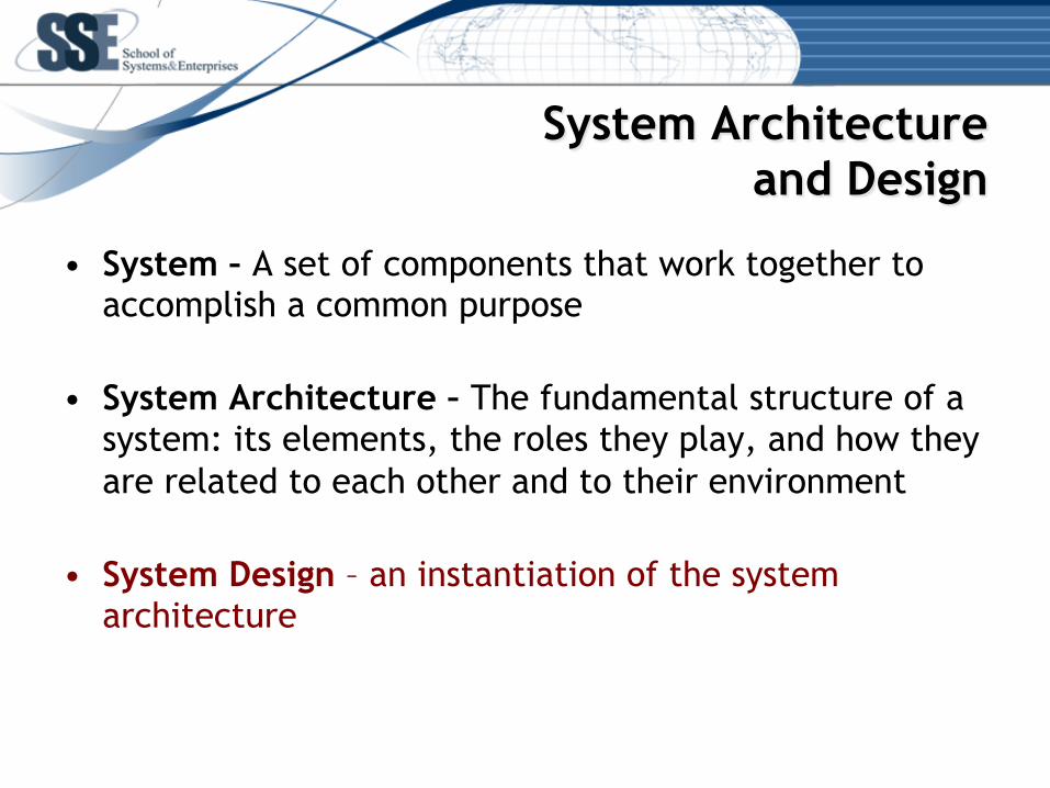
• System – A set of components that work together to accomplish a common purpose
• System Architecture – The fundamental structure of a system: its elements, the roles they play, and how they are related to each other and to their environment
• System Design – an instantiation of the system architecture
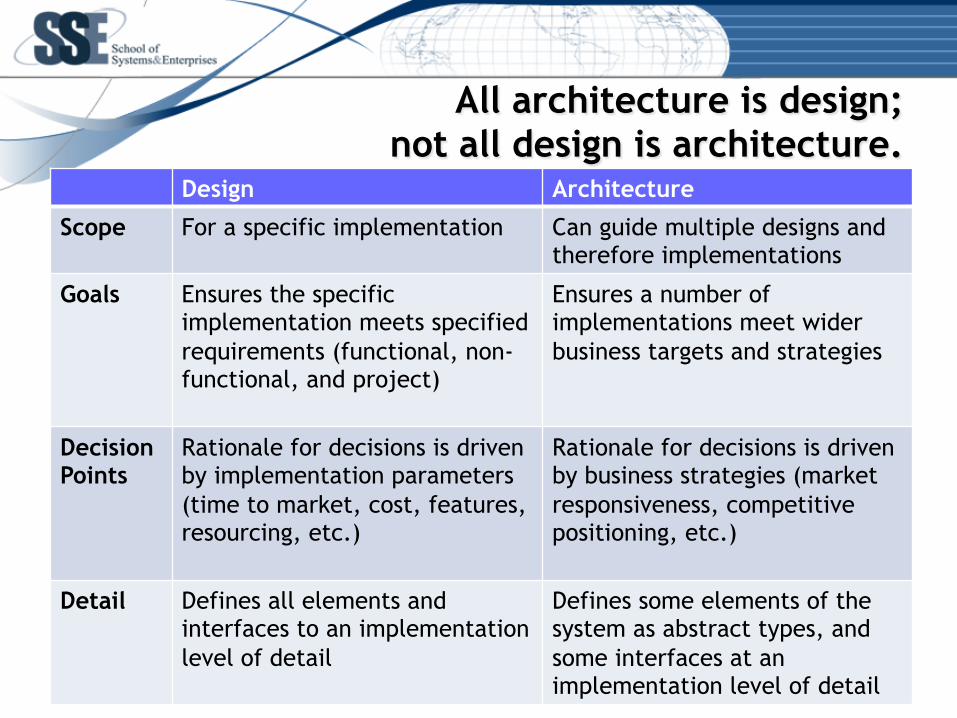
All architecture is design; not all design is architecture.
Design Architecture
Scope For a specific implementation Can guide multiple designs and therefore implementations
Goals Ensures the specific implementation meets specified requirements (functional, non-functional, and project)
Ensures a number of implementations meet wider business targets and strategies
Decision Points
Rationale for decisions is driven by implementation parameters (time to market, cost, features, resourcing, etc.)
Rationale for decisions is driven by business strategies (market responsiveness, competitive positioning, etc.)
Detail Defines all elements and interfaces to an implementation level of detail
Defines some elements of the system as abstract types, and some interfaces at an implementation level of detail

System Architecture
• System – A set of components that work together to accomplish a common purpose
• System Architecture – The fundamental organization of a system embodied in its components, their relationships to each other and to the environment, and the principles guiding its design and evolution. Ref: ANSI/IEEE 1471-2000 – Also, the artifacts that describe this structure

System Architecture – “The Map Is Not the Territory”
System Architecture Architectural
Products

Traditional Views of a Building Architecture
Plan View
Front Elevation View
Side Elevation View
23
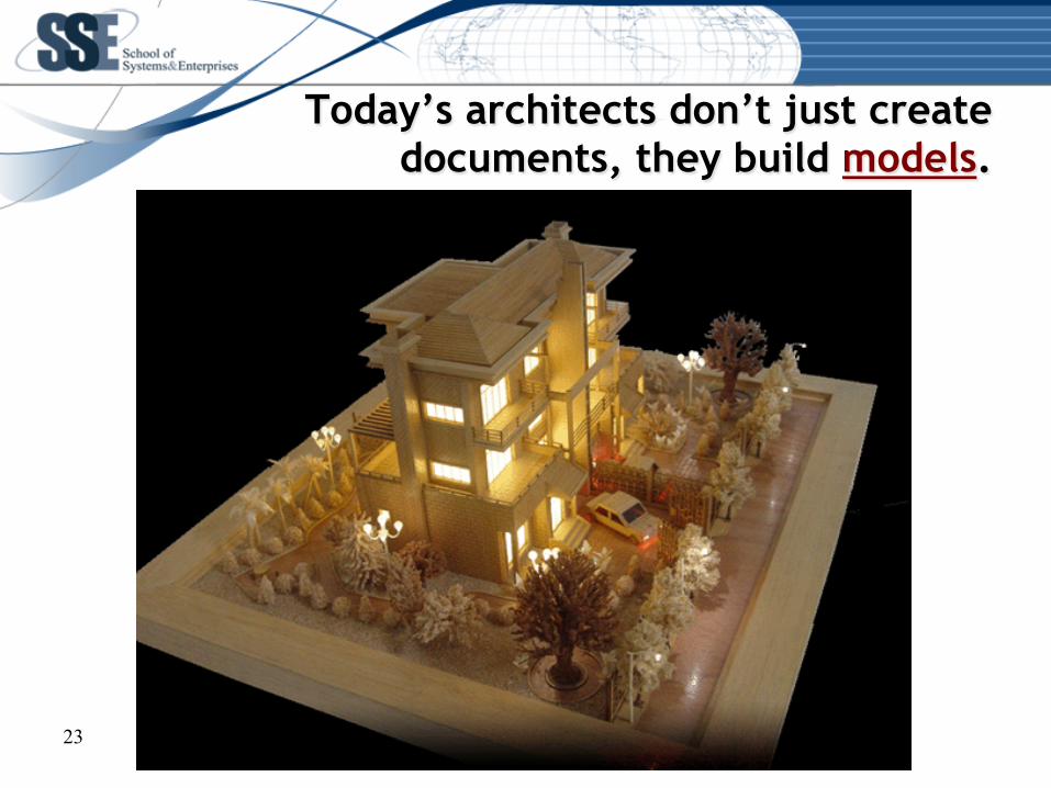
Today’s architects don’t just create documents, they build models.
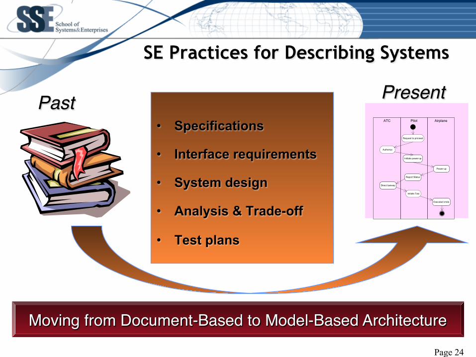
SE Practices for Describing Systems
• Specifications
• Interface requirements
• System design
• Analysis & Trade-off
• Test plans
Moving from Document-Based to Model-Based Architecture
AirplaneATC Pilot
Request to proceed
Authorize
Power-up
Initiate power-up
Direct taxiway
Report Status
Executed cmds
Initiate Taxi
Past Present
Page 24
Model-Based Architecture
• A system model: – Is the primary product of model-based systems
engineering – Incorporates all the system requirements, functional
elements, physical components and the relationships between them in a single repository
– Requires some sort of tool, since there is no way to represent all this information at a single time
– Is able to provide consistent “views” required by the system designers and a wide range of stakeholders, all derived from the same source
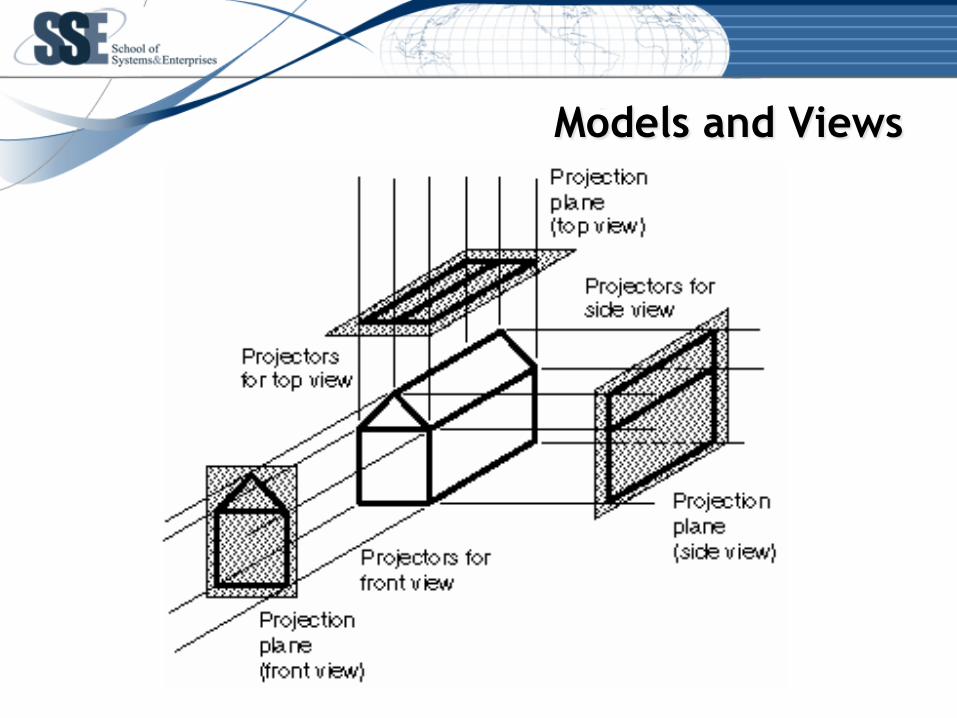
Models and Views
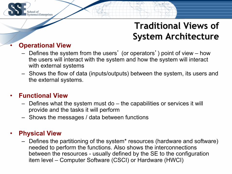
Traditional Views of System Architecture
• Operational View – Defines the system from the users’ (or operators’) point of view – how
the users will interact with the system and how the system will interact with external systems
– Shows the flow of data (inputs/outputs) between the system, its users and the external systems.
• Functional View – Defines what the system must do – the capabilities or services it will
provide and the tasks it will perform – Shows the messages / data between functions
• Physical View – Defines the partitioning of the system* resources (hardware and software)
needed to perform the functions. Also shows the interconnections between the resources - usually defined by the SE to the configuration item level – Computer Software (CSCI) or Hardware (HWCI)
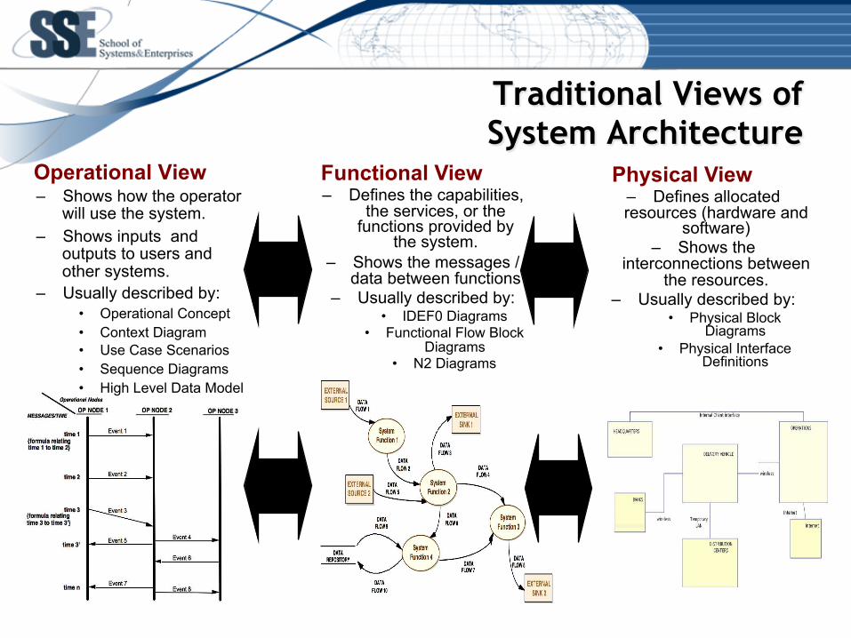
Operational View – Shows how the operator
will use the system. – Shows inputs and
outputs to users and other systems.
– Usually described by: • Operational Concept • Context Diagram • Use Case Scenarios • Sequence Diagrams • High Level Data Model
Functional View – Defines the capabilities,
the services, or the functions provided by
the system. – Shows the messages /
data between functions – Usually described by:
• IDEF0 Diagrams • Functional Flow Block
Diagrams • N2 Diagrams
Physical View – Defines allocated resources (hardware and
software) – Shows the
interconnections between the resources.
– Usually described by: • Physical Block
Diagrams • Physical Interface
Definitions
Traditional Views of System Architecture
Part 2: The Functional View
8/1/16 29
30
Functional View of a System
• Elements – functions; the tasks the system performs
• Interrelationships between the elements – the data, information, material or energy exchanged between functions in order to accomplish the tasks
31
Functions in Systems Engineering
• A function is a process that transforms inputs into outputs
• A function describes an action taken by the system or by one of its elements
• A function is represented by a verb or verb-noun phrase
32
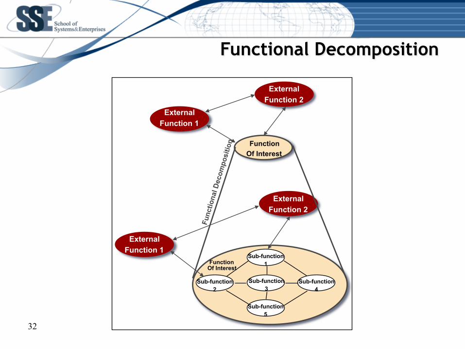
Functional Decomposition
Function Of Interest
External Function 2
External Function 1
External Function 1
External Function 2
Function Of Interest
Sub-function 1
Sub-function 3
Sub-function 2
Sub-function 4
Sub-function 5
Func
tiona
l Dec
ompo
sitio
n
33
Decomposition vs. Composition
• Decompositon (top-down) – Partition system function a level at a time
– Need sound definition of all inputs & outputs
• Composition (bottom-up) – Define many functionalities (bottom-level functions)
– Synthesize functional hierarchy from many bottom-level functions
• Use both to develop the best solution
34
Functional Building Blocks
• Signal functions – generate, receive, transmit, convert or distribute signals
• Information functions – analyze, interpret, query, store or convert information
• Material functions – support, enclose, store, reshape or transport matter
• Energy functions – generate, transform, or control: thrust, torque, power, heat or motion
More examples? Question – Are these elements hardware or software?

Part 3: ATM Example
8/1/16 35
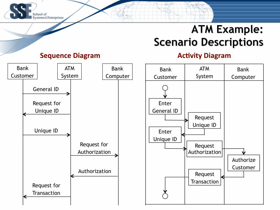
General ID
Request for Authorization
Unique ID
Request for Transaction
Authorization
Bank Customer
ATM System
Bank Computer
Request for Unique ID
Bank Customer
ATM System
Bank Computer
Enter General ID
Request Authorization
Enter Unique ID
Request Unique ID
Authorize Customer
Request Transaction
Sequence Diagram Ac0vity Diagram
ATM Example: Scenario Descriptions

ATM Example: Inputs and Outputs
Provide ATM
Services
General ID
Request for Authorization
Unique ID
Request for Transaction
Authorization
Bank Customer
ATM System
Bank Computer
Request for Unique ID
Sequence Diagram
General ID Request for Unique ID
Unique ID Request for
Authorization
Request for Transaction
Authorization
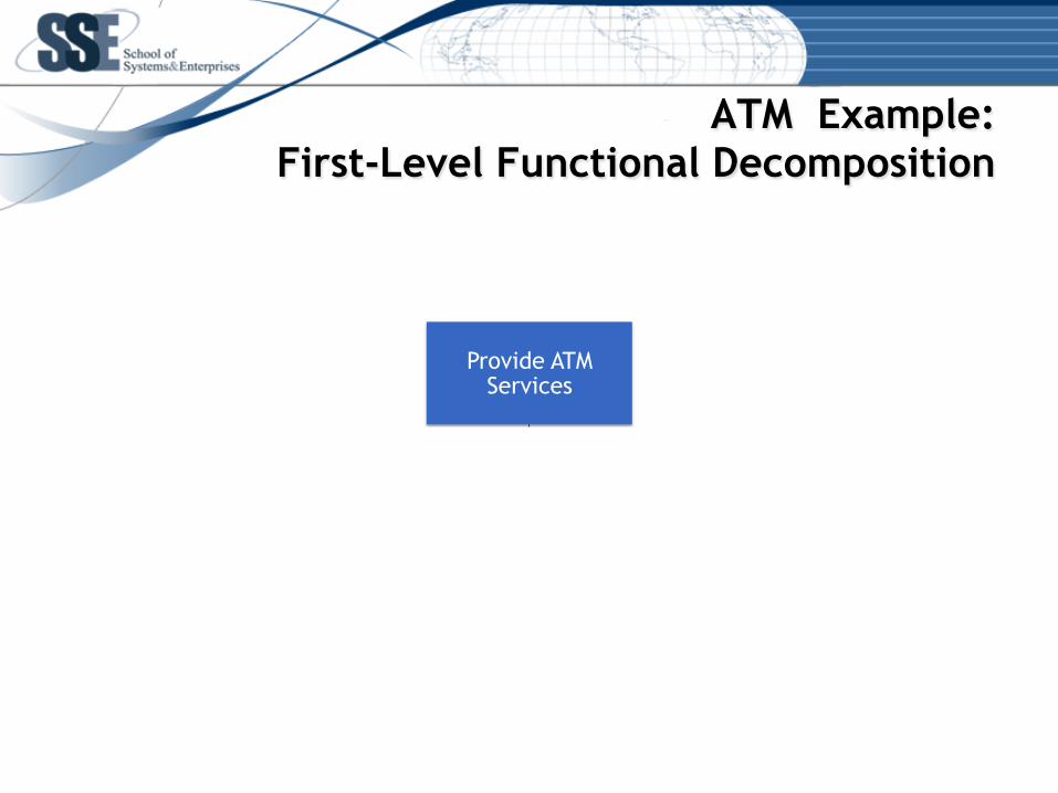
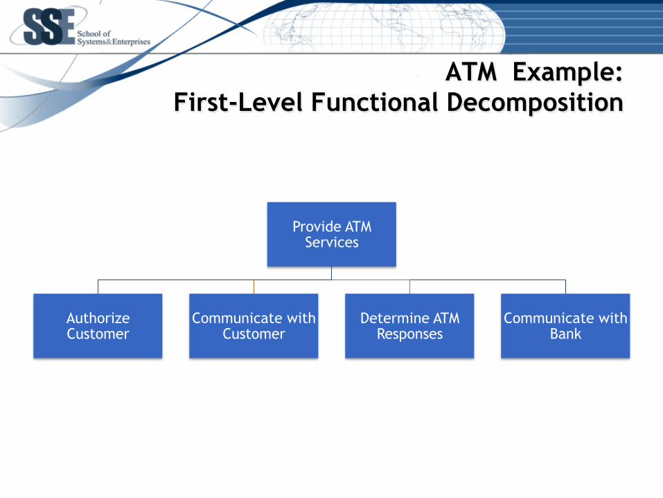
ATM Example: First-Level Functional Decomposition
Provide ATM Services
Authorize Customer
Communicate with Customer
Determine ATM Responses
Communicate with Bank
ATM Example: First-Level Functional Decomposition
Provide ATM Services
Authorize Customer
Communicate with Customer
Determine ATM Responses
Communicate with Bank

ATM Example: Input and Output Assignment
Authorize Customer
Authorization
General ID Request for Unique ID
Unique ID
Request for Authorization
Request for Transaction
Communicate with
Customer
Determine ATM
Responses
Communicate with Bank
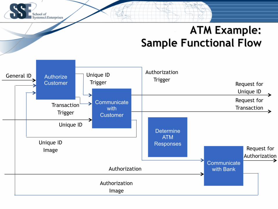
ATM Example: Sample Functional Flow
Authorize Customer
Authorization
General ID
Request for Unique ID
Unique ID
Request for Authorization
Request for Transaction
Communicate with
Customer
Determine ATM
Responses
Communicate with Bank
Authorization Trigger
Unique ID Trigger
Unique ID Image
Transaction Trigger
Authorization Image
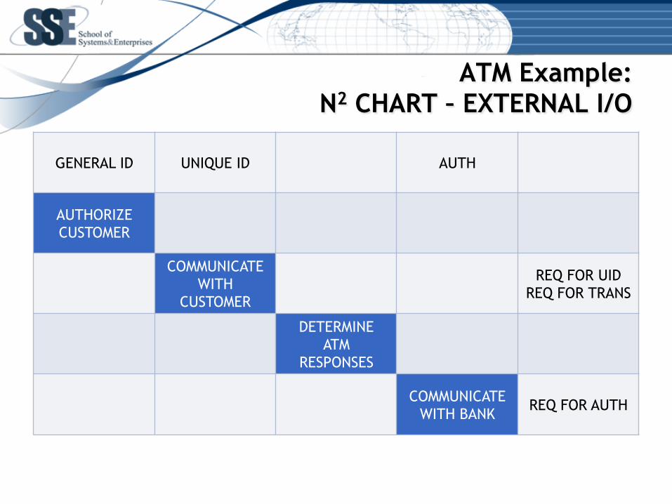
ATM Example: N2 CHART – EXTERNAL I/O
GENERAL ID
UNIQUE ID
AUTH
AUTHORIZE CUSTOMER
COMMUNICATE WITH
CUSTOMER
REQ FOR UID REQ FOR TRANS
DETERMINE ATM
RESPONSES
COMMUNICATE WITH BANK
REQ FOR AUTH

ATM Example: N2 CHART – COMPLETE
GENERAL ID
UNIQUE ID
AUTH
AUTHORIZE CUSTOMER
UID TRIGGER TRANS TRIGGER
AUTH TRIGGER
UID IMAGE
COMMUNICATE WITH
CUSTOMER
REQ FOR UID REQ FOR TRANS
DETERMINE ATM
RESPONSES
AUTH IMAGE COMMUNICATE
WITH BANK
REQ FOR AUTH
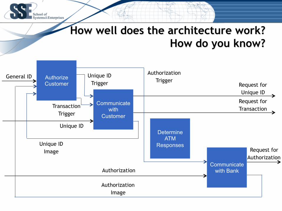
How well does the architecture work? How do you know?
Authorize Customer
Authorization
General ID
Request for Unique ID
Unique ID
Request for Authorization
Request for Transaction
Communicate with
Customer
Determine ATM
Responses
Communicate with Bank
Authorization Trigger
Unique ID Trigger
Unique ID Image
Transaction Trigger
Authorization Image
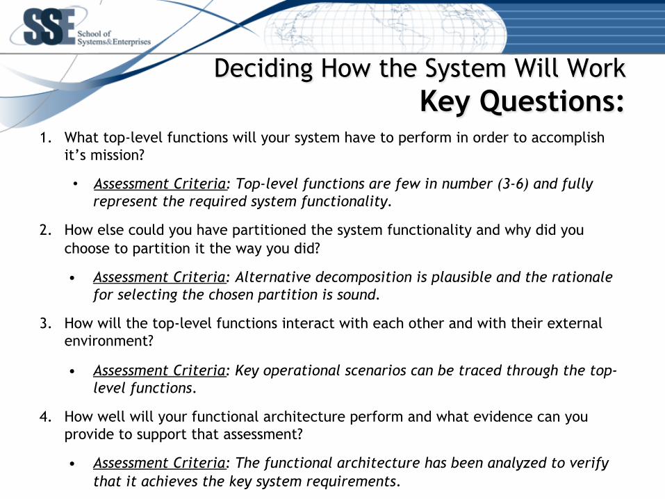
1. What top-level functions will your system have to perform in order to accomplish it’s mission?
• Assessment Criteria: Top-level functions are few in number (3-6) and fully represent the required system functionality.
2. How else could you have partitioned the system functionality and why did you choose to partition it the way you did?
• Assessment Criteria: Alternative decomposition is plausible and the rationale for selecting the chosen partition is sound.
3. How will the top-level functions interact with each other and with their external environment?
• Assessment Criteria: Key operational scenarios can be traced through the top-level functions.
4. How well will your functional architecture perform and what evidence can you provide to support that assessment?
• Assessment Criteria: The functional architecture has been analyzed to verify that it achieves the key system requirements.
Deciding How the System Will Work Key Questions: