Embed Size (px)
Citation preview
Building 3, Torre Diamante, Milan Structural design of a steel tower
German Steel Day, Aachen, 19/10/2012
Ing. Enrico Manganelli
2
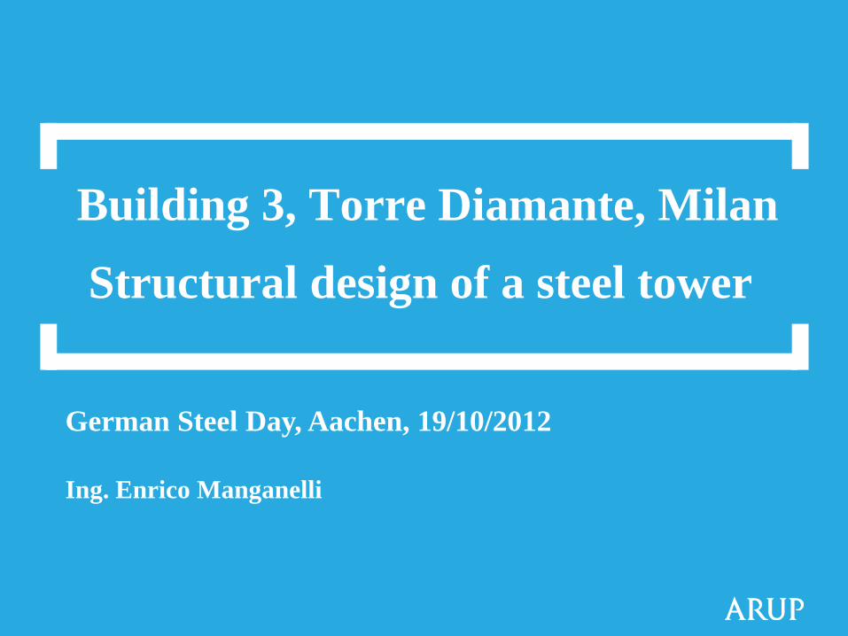
The Project: Varesine urban development, Milan
Client: HINES Italia SGR S.p.A. Porta Nuova Varesine
Architect: Kohn Pedersen Fox Associates Pc.
Structural Engineer and technical site support: ARUP
Steel structures: Stahlbau Pichler
Steel producers: (S460M) Arcelor Mittal
Beginning of the design phase: year 2006
End of desing phase: year 2009
Beginning of Construction: year 2009
End of Construction: construction in progress

3
Central station Porta Garibaldi
station
Site location
4
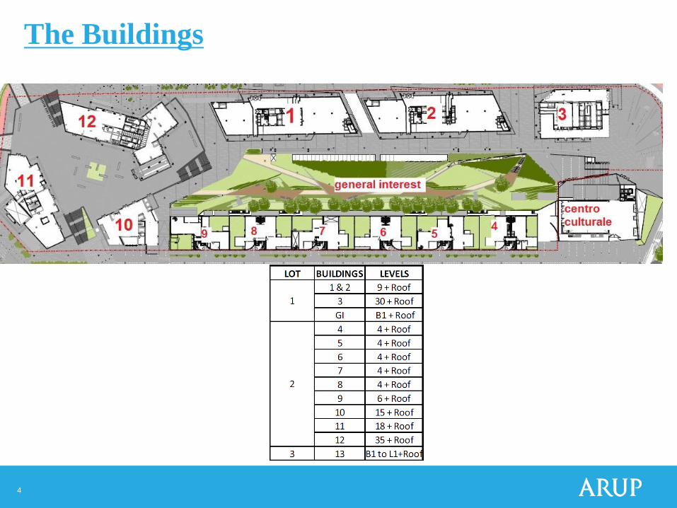
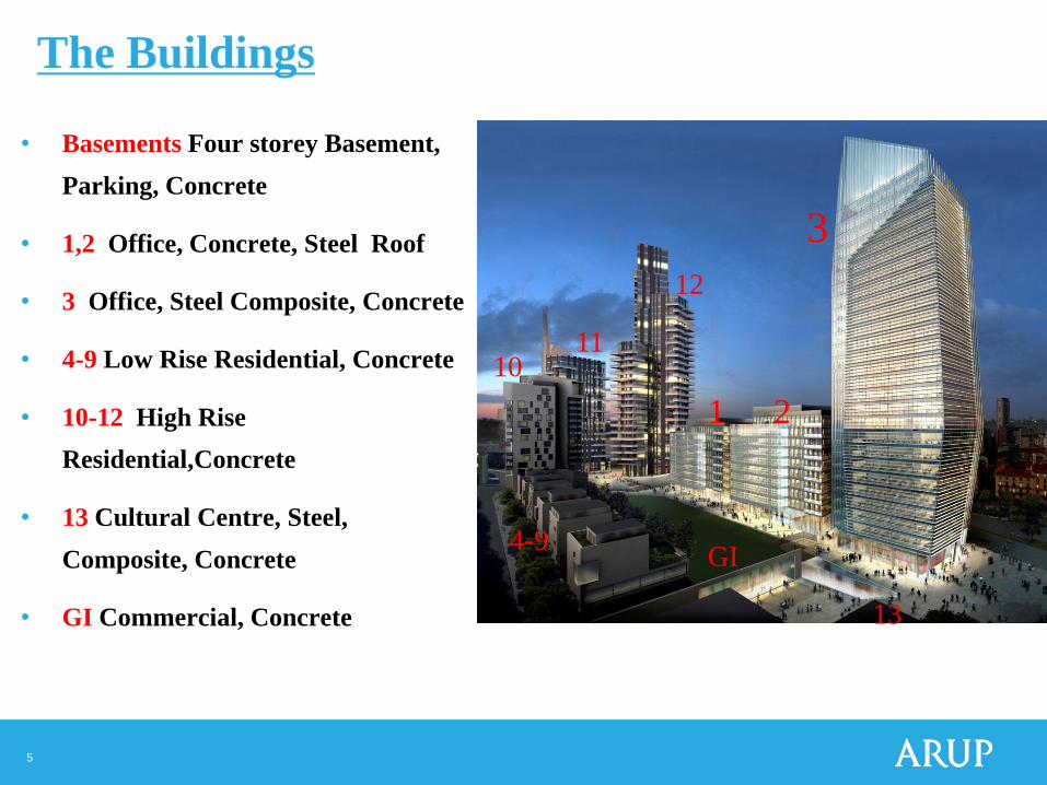
The Buildings
5
• Basements Four storey Basement,
Parking, Concrete
• 1,2 Office, Concrete, Steel Roof
• 3 Office, Steel Composite, Concrete
• 4-9 Low Rise Residential, Concrete
• 10-12 High Rise
Residential,Concrete
• 13 Cultural Centre, Steel,
Composite, Concrete
• GI Commercial, Concrete
1 2
3
12
11 10
4-9 GI
13
Progetto e re alizzazione della Torre Diamante The Buildings
6
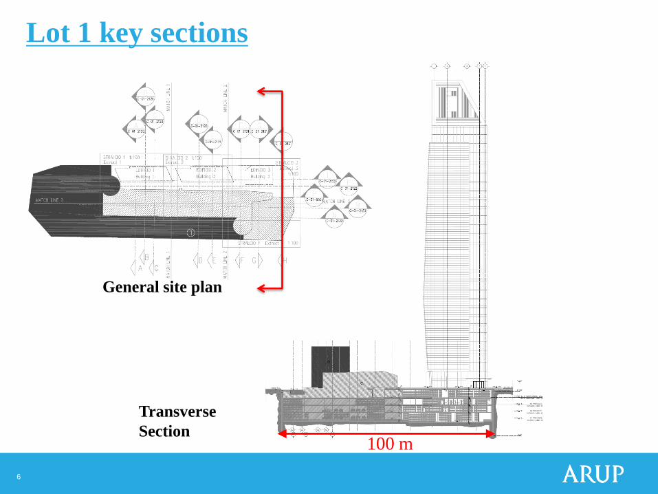
100 m
Transverse
Section
General site plan
Lot 1 key sections
7
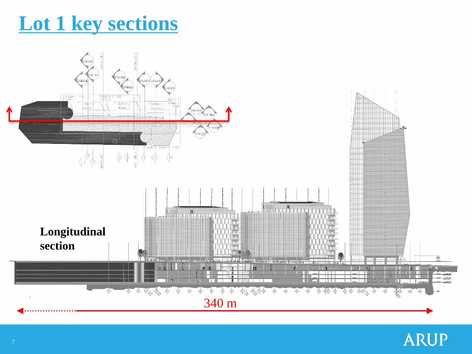
340 m
Longitudinal
section
Lot 1 key sections
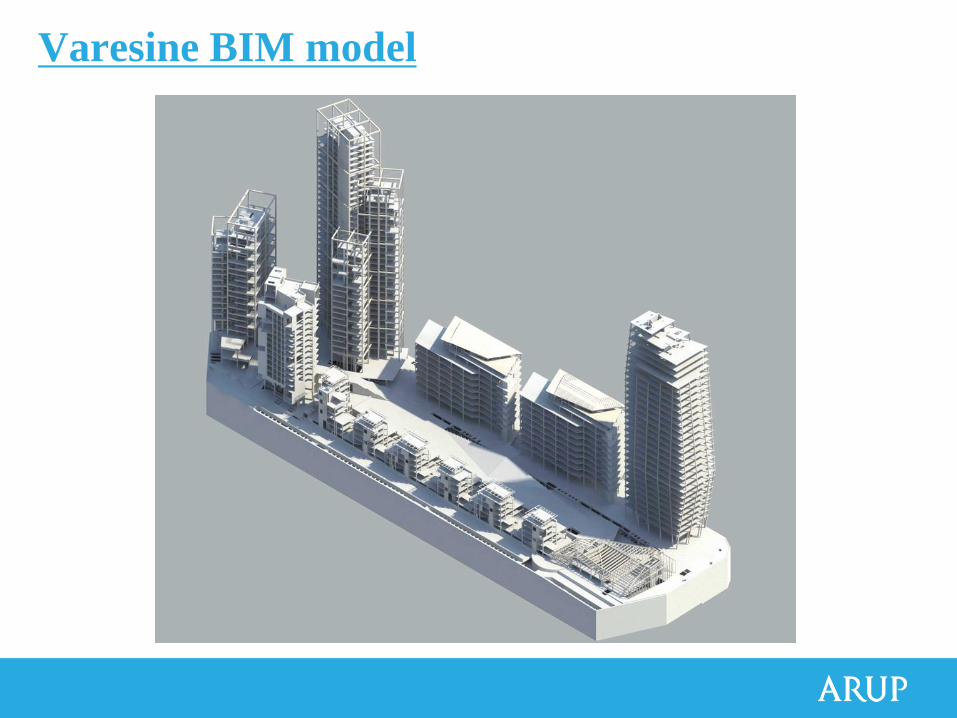
Varesine BIM model
9
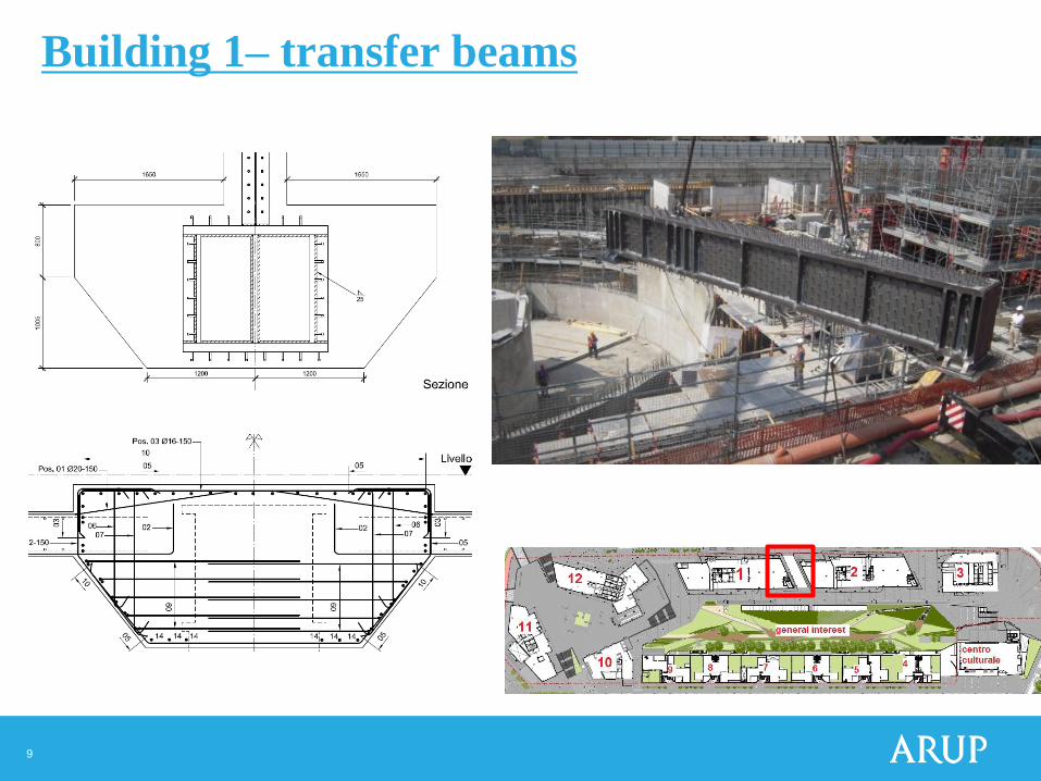
Building 1– transfer beams
10
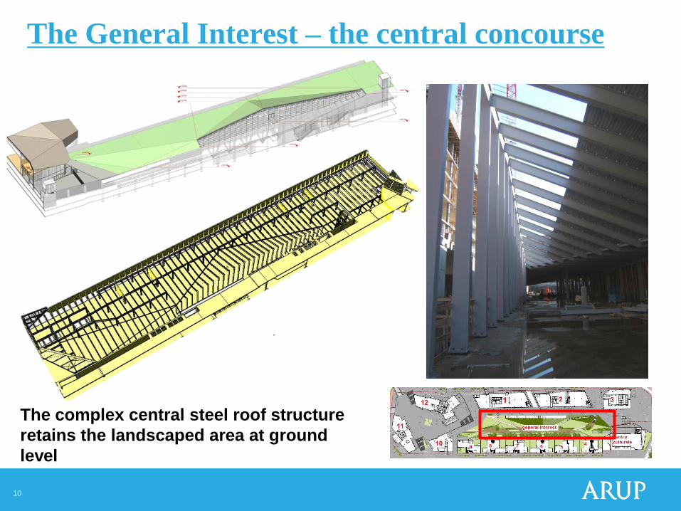
The complex central steel roof structure
retains the landscaped area at ground
level
The General Interest – the central concourse
11
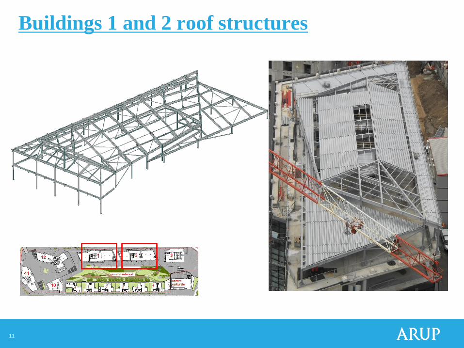
Buildings 1 and 2 roof structures
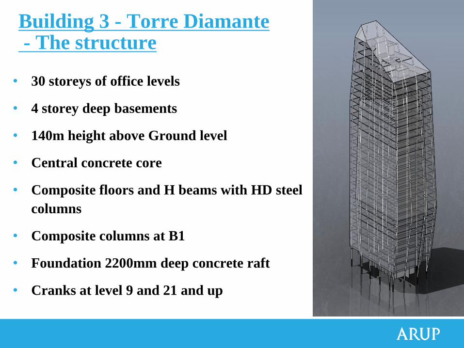
• 30 storeys of office levels
• 4 storey deep basements
• 140m height above Ground level
• Central concrete core
• Composite floors and H beams with HD steel
columns
• Composite columns at B1
• Foundation 2200mm deep concrete raft
• Cranks at level 9 and 21 and up
Building 3 - Torre Diamante - The structure
13
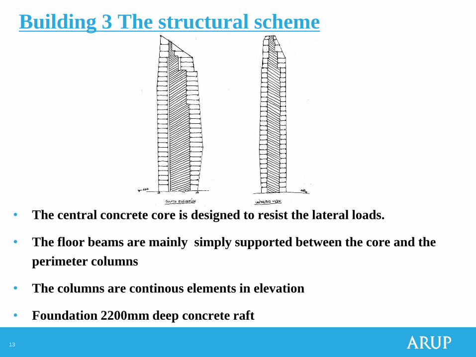
• The central concrete core is designed to resist the lateral loads.
• The floor beams are mainly simply supported between the core and the
perimeter columns
• The columns are continous elements in elevation
• Foundation 2200mm deep concrete raft
Building 3 The structural scheme
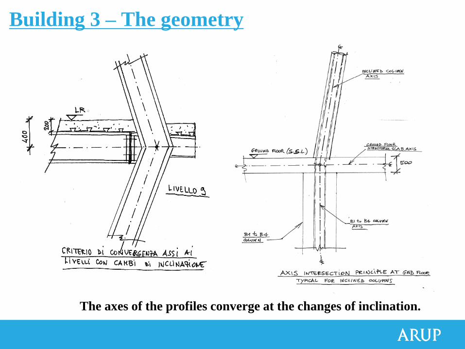
The axes of the profiles converge at the changes of inclination.
Building 3 – The geometry
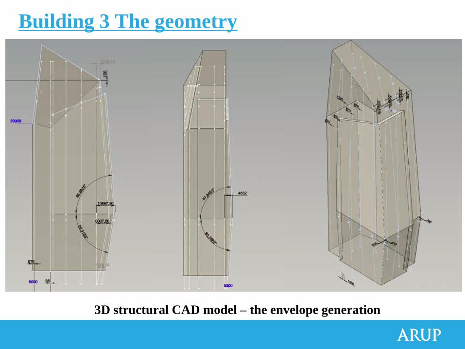
3D structural CAD model – the envelope generation
Building 3 The geometry
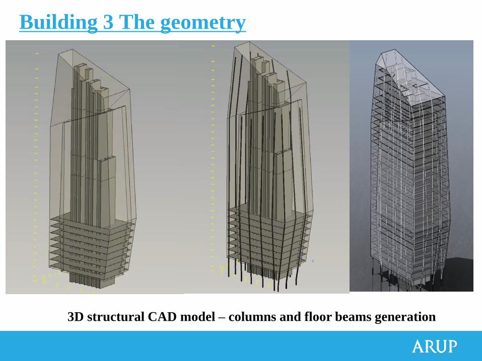
3D structural CAD model – columns and floor beams generation
Building 3 The geometry
17
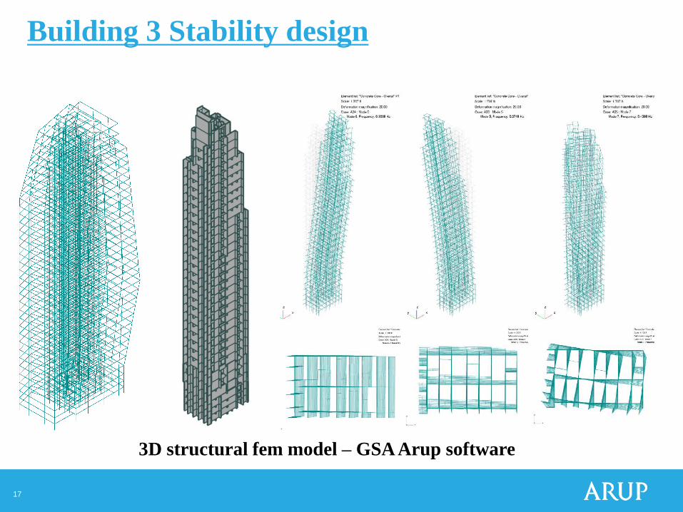
3D structural fem model – GSA Arup software
Building 3 Stability design
18
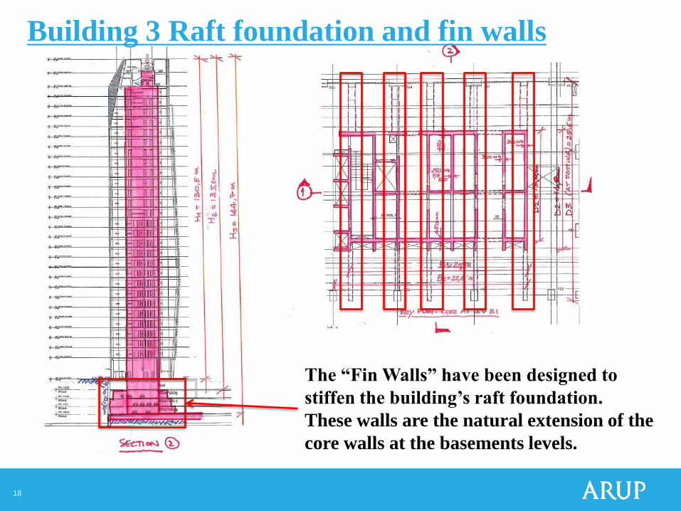
The “Fin Walls” have been designed to
stiffen the building’s raft foundation.
These walls are the natural extension of the
core walls at the basements levels.
Building 3 Raft foundation and fin walls
19
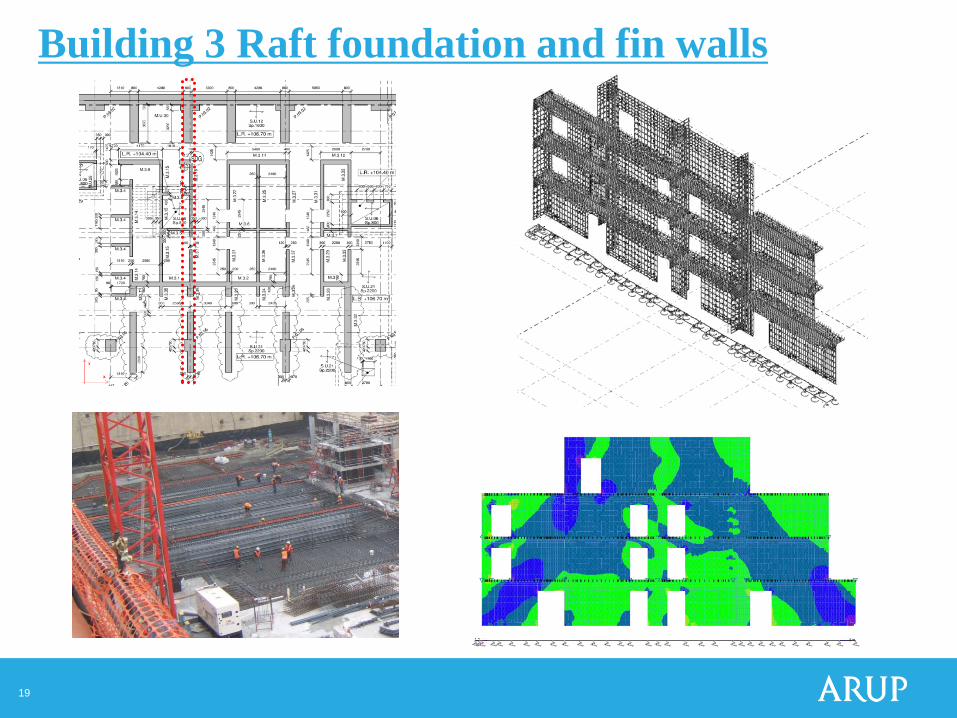
Building 3 Raft foundation and fin walls
20
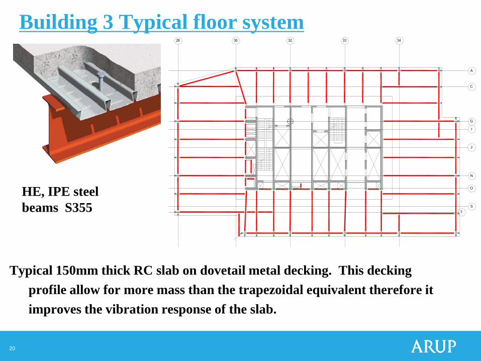
Typical 150mm thick RC slab on dovetail metal decking. This decking
profile allow for more mass than the trapezoidal equivalent therefore it
improves the vibration response of the slab.
A
C
G
I
J
N
O
S
T
Building 3 Typical floor system
HE, IPE steel
beams S355
21
xy z
Element l ist: al l not "soletta"
Scale: 1:248.
xy
z
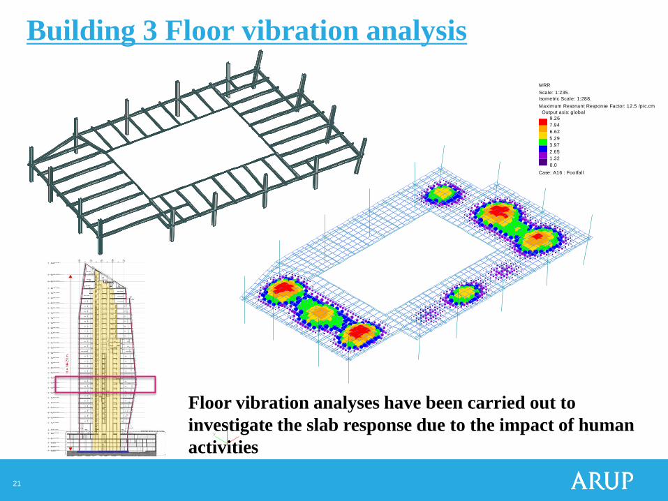
MRR
Scale: 1:235.
Isometric Scale: 1:288.
Maximum Resonant Response Factor: 12.5 /pic.cm
Output axis: global
9.26
7.94
6.62
5.29
3.97
2.65
1.32
0.0
Case: A16 : Footfal l
Floor vibration analyses have been carried out to
investigate the slab response due to the impact of human
activities
Building 3 Floor vibration analysis
22
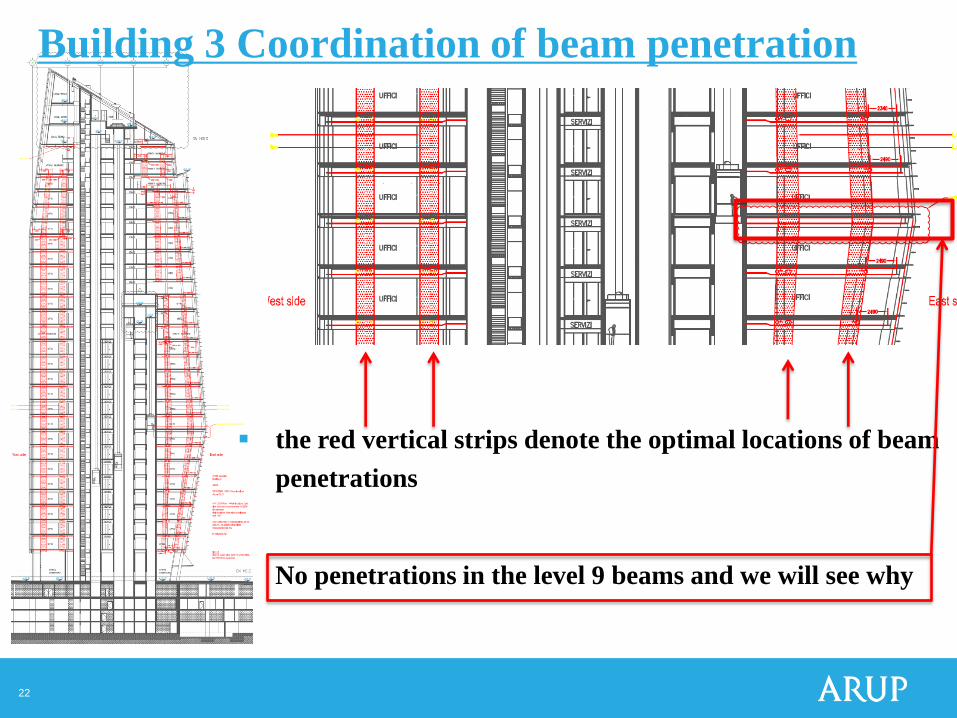
the red vertical strips denote the optimal locations of beam
penetrations
No penetrations in the level 9 beams and we will see why
Building 3 Coordination of beam penetration
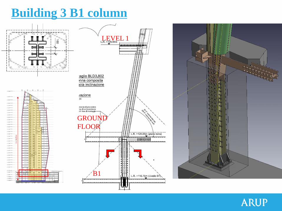
Building 3 B1 column
.
LEVEL 1
GROUND
FLOOR
B1
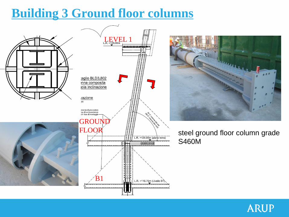
steel ground floor column grade
S460M
LEVEL 1
GROUND
FLOOR
B1
Building 3 Ground floor columns
Progetto e realizzazione della Torre Diamante
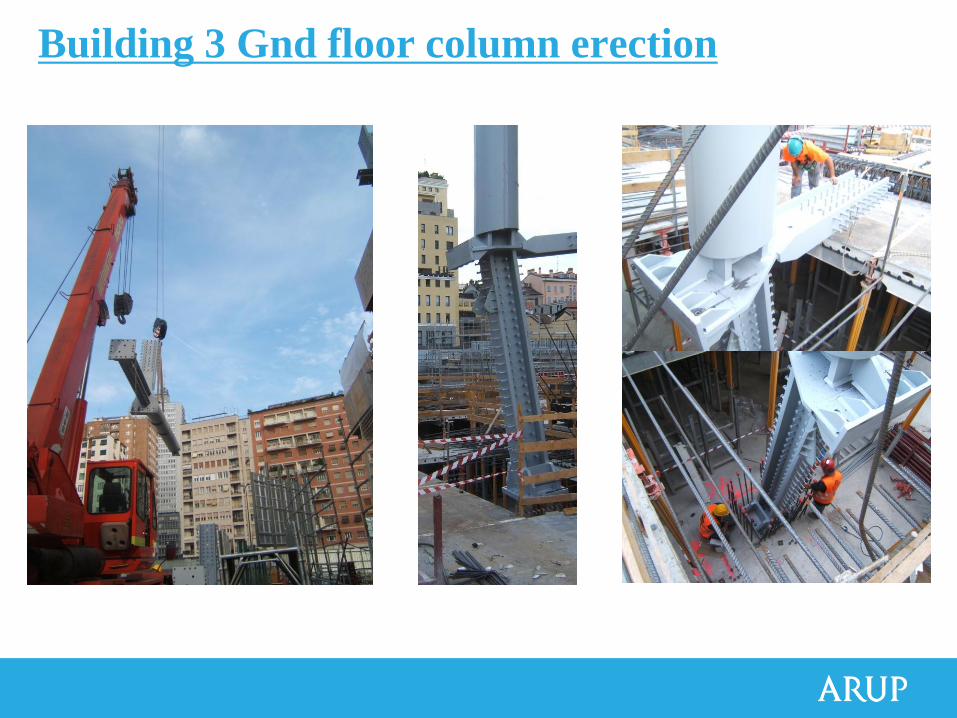
Building 3 Gnd floor column erection
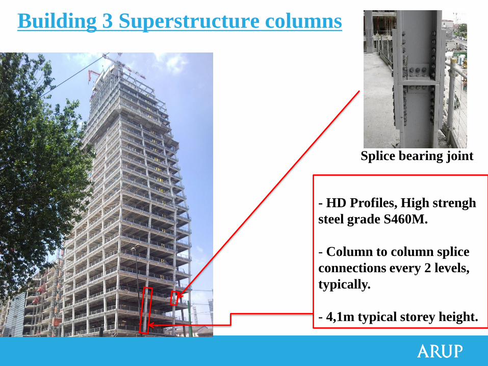
- HD Profiles, High strengh
steel grade S460M.
- Column to column splice
connections every 2 levels,
typically.
- 4,1m typical storey height.
Splice bearing joint
Building 3 Superstructure columns
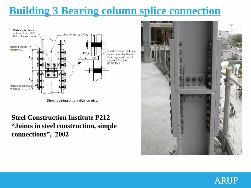
Steel Construction Institute P212
“Joints in steel construction, simple
connections”, 2002
Building 3 Bearing column splice connection

28
Building 3 Building 3 Horizontal bracing level 9 (level 22 similar)
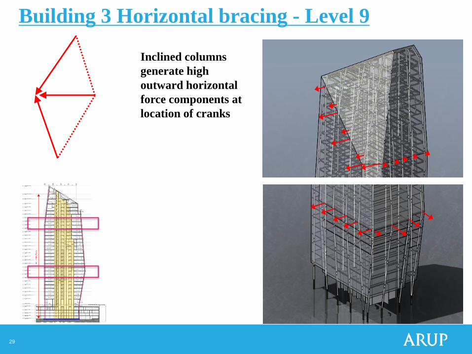
29
Inclined columns
generate high
outward horizontal
force components at
location of cranks
Building 3 Horizontal bracing - Level 9

30
A floor bracing system has been design to transfer the
horizontal forces into the core
A
C
G
I
J
N
O
S
T
Building 3 Horizontal bracing - Level 9
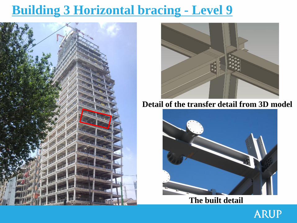
Detail of the transfer detail from 3D model
The built detail
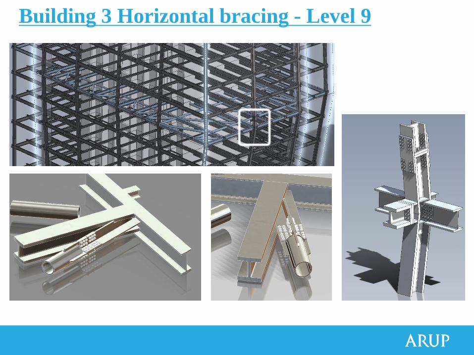
Building 3 Horizontal bracing - Level 9
Building 3 Horizontal bracing - Level 9
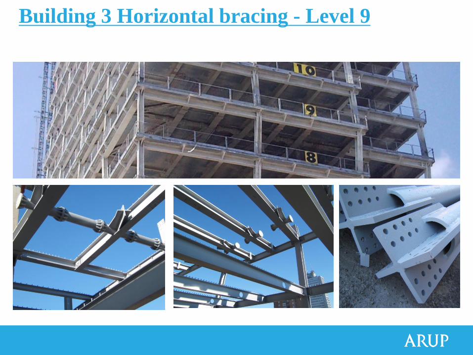
Building 3 Horizontal bracing - Level 9
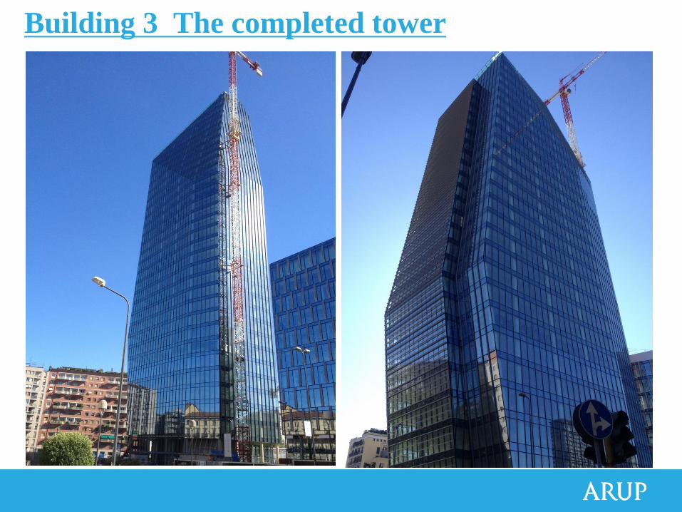
Building 3 The completed tower
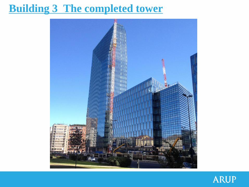
Building 3 The completed tower
Progetto e realizzazione della Torre Diamante