Embed Size (px)
Citation preview

Page 1 of 1
Building #2163-WHL Warehouse Lab Interior Buildout For USF St. Petersburg Facilities Services WDA Project # 1504-08 USF Project Number: PD245016450501 ADDENDUM NUMBER TWO (2) July 13th, 2016 DATE OF CONTRACT DOCUMENTS: January 22, 2016 ISSUED TO BID: June, 2016 BID DATE: July 15, 2016 The following changes, additions, modifications, deletions and clarifications to the Contract Documents dated as shown are herewith issued and shall be made under this Addendum Number 2 as a part of the Bid Proposal submitted to the Owner. CONTENTS: REQUEST FOR INFORMATION (RFI)
1. Attached RFI log with responses.
ADDITIONAL PRODUCT SPECIFICATION
1. Attached new Section 10110 Visual Display Boards. 2. Attached new Section 12510 Window Treatment. 3. Attached product cut-sheet for projector ceiling mount structural support.
INSTRUCTIONS 1. The Addendum is issued prior to the receipt of bids. 2. All work covered in this Addendum is subject to the General and Special Conditions. 3. This Addendum shall be acknowledged on the Proposal Form and the cost of the work herein
specified shall be included in the Base Bid. 4. If this Addendum lists additional acceptable manufacturers, manufacturers listed remain
responsible for meeting the design and performance criteria of specifications and drawings, as shown.
End of Addendum #2.

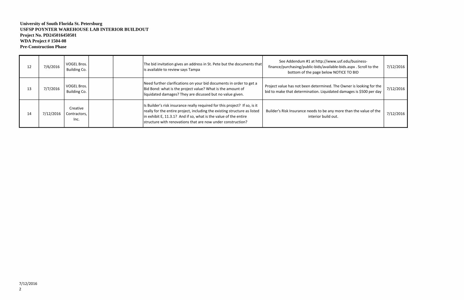
University of South Florida St. PetersburgUSFSP POYNTER WAREHOUSE LAB INTERIOR BUILDOUTProject No. PD245016450501WDA Project # 1504-08Pre-Construction Phase
RFI No.Date
Submitted Submitted By Trade Sheet/Spec Question ResponseDate
Answered1 6/30/2016 CPPI A7.0 Clarify if page A7.0 is not in phase 2 drawings Not in Phase 2 7/12/2016
2 6/30/2016 CPPI Section 01230Clarify alternate #1 for window replacement is in this project, not found in Phase 2 drawings
Not in Phase 2 7/12/2016
3 6/30/2016 CPPI Clarify construction time for this project See Addendum #1 7/12/2016
4 7/6/2016 DPR SpecialtiesA1.2, Marker & Tack Boards
Please provide a specification for the marker board (MBO1‐MB03) and tack boards (TB01‐TB04)
See Addendum #2 attachment: Section 10110 ‐ Visual Display Board 7/12/2016
5 7/6/2016 DPR SpecialtiesA1.2, 102650 Wall Protection
1/A.2 shows Corner Guards (CG1) only at the 90 degree corners in the corridor. The Equipment Legend indicates to provide corner guards at all major corridor intersections. The specifications reference 90 degree or 135 degree corners. Should we include corner guards at the 135 degree corners in the corridor?
Yes 7/12/2016
6 7/6/2016 DPR Plumbing Section 221116The Piping Schedule in Sectin 3.18 of Specification 221116 does not indicate the type of piping required for the RO water systems. Please provide.
The RO system piping shall follow the requirements of the above ground domestic water piping.
7/12/2016
7 7/6/2016 DPRPlumbing/ Painting
Section 220500
Specification 22 05 00, Section 1.32 indicates to "provide painting and touch‐up painting of exposed piping, ductwork, support structures, etc. Refer to Section 15190 for color scheme requirements of pipes and identification markers." This spec was not provide. If it required to paint and color code the exposed ductwork and piping please provide scheme.
Please reference 23 05 53 Identification for HVAC Piping and Equipment (old 15190 section), for identifaction requirements.
7/12/2016
8 7/6/2016 DPR Specialties A1.2 & A3.0Please provide a specification for AV‐01, Ceiling Support Assembly & Projector
Support assembly by Contractor, Projector by Owner. See attached product cut‐shet for projector ceiling structural support.
7/12/2016
9 7/6/2016 DPR Equipment A1.2 Please provide a specification for EQ‐01, Window Treatment See Addendum #2 attachment: Section 12510 ‐ Window Treatment 7/12/2016
10 7/6/2016VOGEL Bros. Building Co.
Bid Documents
We were told the bid date was moving to the 8th. Is there going to be an addendum put out changing the bid date?
See Addendum #1 7/12/2016
11 7/6/2016VOGEL Bros. Building Co.
PlumbingThe Piping Schedule in Sectin 3.18 of Specification 221116 does not indicate the type of piping required for the RO water systems. Please provide.
The RO system piping shall follow the requirements of the above ground domestic water piping.
7/12/2016
7/12/20161
University of South Florida St. PetersburgUSFSP POYNTER WAREHOUSE LAB INTERIOR BUILDOUTProject No. PD245016450501WDA Project # 1504-08Pre-Construction Phase
12 7/6/2016VOGEL Bros. Building Co.
The bid invitation gives an address in St. Pete but the documents that is available to review says Tampa
See Addendum #1 at http://www.usf.edu/business‐finance/purchasing/public‐bids/available‐bids.aspx . Scroll to the
bottom of the page below NOTICE TO BID7/12/2016
13 7/7/2016VOGEL Bros. Building Co.
Need further clarifications on your bid documents in order to get a Bid Bond: what is the project value? What is the amount of liquidated damages? They are dicussed but no value given.
Project value has not been determined. The Owner is looking for the bid to make that determination. Liquidated damages is $500 per day
7/12/2016
14 7/12/2016Creative
Contractors, Inc.
Is Builder’s risk insurance really required for this project? If so, is it really for the entire project, including the existing structure as listed in exhibit E, 11.3.1? And if so, what is the value of the entire structure with renovations that are now under construction?
Builder's Risk Insurance needs to be any more than the value of the interior build out.
7/12/2016
7/12/20162
SECTION 10110 - 1 VISUAL DISPLAY BOARDS
#1504-08
USFSP WAREHOUSE LAB BUILDOUT
100% CONSTRUCTION DOCUMENTS – PERMIT SET JANUARY 22, 2016
SECTION 10110 – VISUAL DISPLAY BOARDS
PART 1 - GENERAL
1.1 RELATED DOCUMENTS
A. Drawings and general provisions of the Contract, including General and Supplementary Conditions and Division 01 Specification Sections, apply to this Section.
1.2 SUMMARY
A. This Section includes the following types of visual display boards:
1. Porcelain enamel markerboards (for liquid chalk). 2. Vinyl-fabric-faced cork tackboards. 3. Tackable wall panels 4. Display rails.
B. Related Sections: The following sections contain requirements that relate to this section:
1. Division 06 Section "Architectural Casework" for tackable surfaces in casework. 2. Division 06 Section “Rough Carpentry” for wood blocking and grounds.
1.4 SUBMITTALS
A. General: Submit the following in accordance with Conditions of the Contract and Division 01 Specification Sections.
B. Product Data: Include manufacturer's data substantiating that markerboard and tackboard materials comply with requirements indicated.
C. Shop Drawings: Provide shop drawings for each type of markerboard and tackboard required. Include sections of typical trim members and dimensioned elevations. Show anchors, grounds, and reinforcement, accessories, layout, and installation details.
D. Samples for Verification: For each type of visual display surface indicated and as follows:
1. Visual Display Surface: Not less than 8-1/2 by 11 inches, mounted on substrate indicated for final Work. Include one panel for each type, color, and texture required.
2. Trim: 6 inch-long sections of each trim profile. 3. Accessories: Full-size Sample of each type of accessory.
E. Samples: Provide the following samples of each product for initial selection of colors, patterns, and textures, as required, and for verification of compliance with requirements indicated.
1. Samples for initial selection of color, pattern, and texture:
SECTION 10110 - 2 VISUAL DISPLAY BOARDS #1504-08
UNIVERSITY OF SOUTH FLORIDA ST. PETERSBURG
HARBOR HALL RENOVATION 100% CONSTRUCTION DOCUMENTS
JUNE 24, 2015
a. Porcelain Enamel Markerboard: Manufacturer's color charts consisting of actual sections of porcelain enamel finish showing the full range of colors available for each type of chalkboard and markerboard required.
b. Vinyl-fabric-faced Cork Tackboards: Manufacturer's color charts consisting of actual sections of vinyl fabric, showing the full range of colors, textures, and patterns available for each type of vinyl-fabric-faced cork tackboard indicated.
F. Certificates: In lieu of laboratory test reports, when permitted by the Architect, submit the manufacturer's certification that vinyl-fabric-faced cork tackboard materials furnished comply with requirements specified for flame spread ratings.
G. Warranties: Special warranties specified in this Section.
1.4 QUALITY ASSURANCE
A. Source Limitations: Obtain each type of visual display surface through one source from a single manufacturer.
B. Installer Qualifications: Engage an experienced Installer who is an authorized representative of the markerboard manufacturer for both installation and maintenance of the type of sliding chalkboard units required for this Project.
1. Maintenance Proximity: Not more than 2 hours' normal travel time from the Installer's place of business to the Project site.
C. Fire Performance Characteristics: Provide vinyl-fabric-faced tackboards with surface burning characteristics indicated below, as determined by testing assembled materials composed of facings and backings identical to those required in this section, in accordance with ASTM E 84, by a testing organization acceptable to authorities having jurisdiction.
1. Flame Spread: 25 or less. 2. Smoke Developed: 10 or less.
1.5 DELIVERY, STORAGE, AND HANDLING
A. Deliver factory-built visual display boards, including factory-applied trim where indicated, completely assembled in one piece without joints, where possible. If dimensions exceed maximum manufactured panel size, provide two or more pieces of equal length as acceptable to maximum manufactured panel size, provide two or more pieces of equal length as acceptable to Architect. When overall dimensions require delivery in separate units, prefit components at the factory, disassemble for delivery, and make final joints at the site.
B. Store visual display units vertically with packing materials between each unit.
1.6 PROJECT CONDITIONS
A. Field Measurements: Verify dimensions by field measurements before fabrication and indicate measurements on Shop Drawings.

SECTION 10110 - 3 VISUAL DISPLAY BOARDS
#1504-08
USFSP WAREHOUSE LAB BUILDOUT
100% CONSTRUCTION DOCUMENTS – PERMIT SET JANUARY 22, 2016
1. Established Dimensions: Where field measurements cannot be made without delaying the Work, establish dimensions and proceed with fabricating visual display surfaces without field measurements. Coordinate wall construction to ensure that actual dimensions correspond to established dimensions.
2. Allow for trimming and fitting where taking field measurements before fabrication might delay the Work.
1.7 WARRANTY
A. Porcelain Enamel Chalkboard Warranty: Furnish the manufacturer's written warranty, agreeing to replace porcelain enamel chalkboards that do not retain their original writing and erasing qualities, become slick and shiny, or exhibit crazing, cracking, or flaking, provided the manufacturer's instructions with regard to handling, installation, protection, and maintenance have been followed.
1. Warranty Period: 25 years from date of Substantial Completion.
PART 2 - PRODUCTS
2.1 MANUFACTURERS
A. Manufacturer: Subject to compliance with requirements, provide products of one of the following:
1. Porcelain Enamel Marker Boards:
a. AARCO Products, Inc. b. American Visual Products, LLC c. Claridge Products and Equipment, Inc. d. Greensteel, Inc. e. K-Pro Specialty Products f. Wenger Corp.
2. Tackboards:
a. AARCO Products, Inc. b. American Visual Products, LLC c. Claridge Products and Equipment, Inc. d. Greensteel, Inc. e. K-Pro Specialty Products f. Wenger Corp.
3. Tackboard Panels:
a. Basis-of-Design: Homasote Co. Pinnacle NCFR Tackboard panels. Paint color: As selected by Architect.

SECTION 10110 - 4 VISUAL DISPLAY BOARDS #1504-08
UNIVERSITY OF SOUTH FLORIDA ST. PETERSBURG
HARBOR HALL RENOVATION 100% CONSTRUCTION DOCUMENTS
JUNE 24, 2015
B. Type: Field Installed Series.
2.2 MATERIALS
A. Size: Single piece units, without joints, in sizes indicated on Drawings.
B. Colors and Textures: Provide colors and textures as selected by Architect from manufacturer’s standards.
C. Markerboards:
1. Porcelain-on-Metal: Balanced, high pressure laminated, 3-ply construction; with facing sheet, core and backing; complying with the following requirements:
a. Facing Sheet: 24 gauge enameling grade steel sheet coated on exposed face with primer, and drymarker cover coat and on concealed face with two (2) coat process of primer and ground coat. Provide permanent fused grid and music line patterns as indicated.
1.) Cover Coat: Drymarker surface coat of high fired porcelain frits .0025" minimum thickness.
2.) Primer Coat: Nickel Cobalt primer .002" minimum thickness.
b. Core: 7/16" thickness, Fiberboard, Class ‘A’. c. Backing Sheet: Aluminum foil, .005" thick.
D. Vinyl-Fabric-Faced Tackboards: Provide mildew-resistant, washable, vinyl fabric complying with FS CCC-W-408, Type II, weighing not less than 13 oz./sq.yd., laminated to 1/2-inch thick fiberboard core. Provide fabric that has a flame spread rating of 25 or less when tested in accordance with ASTM E 84.
E. Tackboard Panels: Provide finely sanded, soft-textured, formaldehyde-free and asbestos free tackboard.
a. Thickness: 3/8”-inch b. Weight: 1.13 lbs/sq.ft
2.3 ACCESSORIES
A. Metal Trim and Accessories: Fabricate frames and trim of not less than 0.062 inch thick aluminum alloy, size and shape as indicated, to suit type of installation. Provide straight, single-length units wherever possible; keep joints to a minimum. Miter corners to a neat, hairline closure.
1. Factory-Applied Trim: Manufacturer’s standard. 2. Where the size of boards or other conditions exist that require support in addition to the
SECTION 10110 - 5 VISUAL DISPLAY BOARDS
#1504-08
USFSP WAREHOUSE LAB BUILDOUT
100% CONSTRUCTION DOCUMENTS – PERMIT SET JANUARY 22, 2016
normal trim, provide structural supports or modify the trim as indicated or as selected by the Architect from the manufacturer's standard structural support accessories to suit the condition indicated.
3. Chalktray: Furnish manufacturer's standard continuous box-type aluminum chalktray with slanted front and cast aluminum end closures for each chalkboard.
4. Map Rail: Furnish map rail at the top of each unit, complete with the following accessories:
a. Display Rail: Provide continuous cork display rail approximately 2 inches wide, as indicated, integral with the map rail.
b. End Stops: Provide one end stop at each end of the map rail. c. Map Hooks: Provide 2 map hooks for each 48 inches of map rail or fraction thereof. d. Flagholder: Provide one flagholder for each room.
5. Special-Purpose Graphics: Fuse or paint the following graphics into surface of porcelain enamel visual display unit:
a. Music staff lines.
6. Provide two erasers and four boxes of dry-erase markers for each markerboard installation.
2.4 FABRICATION
A. Porcelain-Enamel Visual Display Assemblies: Laminate porcelain-enamel face sheet and backing sheet to core material under heat and pressure with manufacturer’s standard flexible, waterproof adhesive. All porcelain-enamel markerboards shall be magnetic.
B. Visual Display Boards: Factory assembled visual display boards, unless otherwise indicated. Trim shall be assembled and attached to visual display boards.
C. Factory-Assembled Visual Display Units: Coordinate factory-assembled units with trim and accessories indicated. Join parts with a neat, precision fit.
1. Make joints only where total length exceeds maximum manufactured length. Fabricate with minimum number of joints, balanced around center of board, as acceptable to Architect.
2. Provide manufacturer’s standard vertical-joint system between abutting sections of markerboards.
3. Provide manufacturer’s standard mullion trim at joints between markerboards and tackboards of combination units.
4. Factory-applied trim shall be assembled and attached to visual display units at manufacturer’s factory before shipment.
D. Aluminum Frames and Trim: Fabricate units straight and of single lengths, keeping joints to a minimum. Miter corner to neat, hairline closure.
2.5 ALUMINUM FINISHES
A. Comply with NAAMM’s “Metal Finishes Manual for Architectural and Metal Products” for recommendations for applying and designating finishes.
SECTION 10110 - 6 VISUAL DISPLAY BOARDS #1504-08
UNIVERSITY OF SOUTH FLORIDA ST. PETERSBURG
HARBOR HALL RENOVATION 100% CONSTRUCTION DOCUMENTS
JUNE 24, 2015
B. Protect mechanical finishes on exposed surfaces from damage by applying a strippable, temporary protective covering before shipping.
C. Finish Designations prefixed by AA comply with the system established by the Aluminum Association for designating aluminum finishes.
D. Class II, Clear Anodic Finish: AA-M12C22A31 (Mechanical Finish: nonspecular as fabricated: Chemical Finish: etched, medium matte; Anodic Coating: Architectural Class II, clear coating 0.010 mm or thicker) complying with AAMA 611.
PART 3 - EXECUTION
3.1 INSTALLATION
A. Deliver factory-built chalkboard and tackboard units completely assembled in one piece without joints, wherever possible. Where dimensions exceed panel size, provide 2 or more pieces of equal length as acceptable to the Architect. When overall dimensions require delivery in separate units, prefit components at the factory, disassemble for delivery, and make final joints at the site. Use splines at joints to maintain surface alignment.
B. Install units in locations and at mounting heights indicated on drawings and in accordance with the manufacturer's instructions. Keep perimeter lines straight, plumb, and level. Provide grounds, clips, backing materials, adhesives, brackets, anchors, trim, and accessories necessary for a complete installation.
3.2 ADJUST AND CLEAN
A. Verify that accessories required for each unit have been properly installed and that operating units function properly.
B. Clean units in accordance with the manufacturer's instructions. Break in chalkboards only as recommended by the manufacturer.
END OF SECTION 10110
SECTION 12510 - 1 WINDOW TREATMENT
#1504-08
USPSP WAREHOUSE LAB BUILDOUT
100% CONSTRUCTION DOCUMENTS – PERMIT SET JANUARY 22, 2016
SECTION 12510 – WINDOW TREATMENT PART 1 - GENERAL 1.01 SUMMARY
A. Provide all labor, materials, tools, fabrications, reinforcement, equipment and services for interior window shades as specified herein and/or as shown, detailed, scheduled, implied, required or otherwise indicated to provide a complete and proper installation.
B. Completely coordinate with Work of all other trades. C. Although such Work is not specifically indicated, furnish and install all supplementary or
miscellaneous items, appurtenances and devices incidental to or necessary for a sound, secure and complete installation.
D. Related Work: 1. Division 0 2. Division 1
1.02 SUBMITTALS
A. Comply with Section 01340. B. Product Data:
1. Materials Lists. 2. Manufacturers Specifications 3. Manufacturers Instructions
C. Shop Drawings: 1. Installation Details.
D. Samples: 1. Color Selector.
1.03 QUALITY ASSURANCE
A. Use adequate numbers of skilled workmen who are thoroughly trained and experienced in
the necessary crafts and who are completely familiar with the specified requirements and the methods needed for proper performance of the Work of this Section.
1.04 DELIVERY, STORAGE AND HANDLING
A. Comply with Section 01630 for Product Options and Substitutions.
PART 2 - PRODUCTS 2.01 MANUFACTURERS AND PRODUCT
A. Basis of Design: Hunter Douglas Architectural. 13915 Danielson St. Ste.100/ Poway, CAL 92064 1. Product : Model CX80 1” Mini Horizontal Aluminum Blinds (Premium Quality) 2. Materials:
SECTION 12510-2 WINDOW TREATMENT #1504-08
UNIVERSITY OF SOUTH FLORIDA ST. PETERSBURG HARBOR HALL RENOVATION
100% CONSTRUCTION DOCUMENTS JUNE 24, 2015
a. Slats: 1” wide x .008” thick, heat-treated and spring tempered aluminum alloy 6011 with eased corners and manufacturing burrs removed. Product to have a minimum of 95% pre-consumer recycled content. Furnish not less than nominal 15.2 slats per foot in colors selected by Architect from manufacturer’s available contract colors utilizing Dust Shield finish to inhibit dust build-up for easier maintenance.
b. Slat Support: Braided ladders of 100% polyester yarn color compatible with slats and spacing of ladder no more than 20mm.
c. Headrail: U-shaped profile with rolled edges, measuring 1” x 1” x 0.024” constructed of corrosion resistant steel. Internally fit with components required for specified performance and designed for smooth, quiet, trouble-free operation. Headrail finish to be standard baked-on polyester and to match slats. Ends fitted with 0.024” steel end lock with adjustable tab for centering blinds.
d. Bottom Rail: Steel, with corrosion-resistant finish formed with double-lock seam into closed oval shape for optimum beam and torsional strength. Ends fitted with color-coordinated engineered polymer caps. Color-coordinated engineered polymer tape buttons secure the ladder and cord. Bottom Rail finish to be standard baked-on polyester color coordinated to slats.
e. Lifting Mechanism: Crashproof cordlock in engineering polymer housing with nickel-plate die-cast bearing surface and brass locking clips, two-ply polyester cord filler in braided polyester jacket lift cords, cord equalizers, cordlock adapter, and Cord Stop/Single Pull Cord. Located on either side of individual blind unit as per architect’s request.
f. Tilting Mechanism: Permanently lubricated die-cast worm and gear type tilter gear mechanism in fully enclosed housing with clutch action to protect ladder tapes from over rotation of the solid steel, corrosion resistant tilt rod.
g. Tilt Control Wand: Tubular construction 9/32” diameter extruded clear acrylic hexagonal, and detachable without tools. Located on either side of individual blind unit as per architect’s request.
h. Mounting Hardware: Manufacturer’s standard 0.040” steel box brackets with baked-on polyester finish to match headrail with additional support brackets for blinds over 60” wide.
3. Aluminum Slat color: To be Selected from the manufacturer’s standard selection.
4. Fabrication: Blind measurements shall be accurate to within +/- 1/8” or as recommended in writing by manufacturer.
5. Manually operated @ each interior side of room /window indicated on plan.
PART 3 - EXECUTION 3.01 INSPECTION

SECTION 12510 - 3 WINDOW TREATMENT
#1504-08
USPSP WAREHOUSE LAB BUILDOUT
100% CONSTRUCTION DOCUMENTS – PERMIT SET JANUARY 22, 2016
A. Verify that the work area in which the blinds will be installed is free to conditions that interfere with blind installations and operations. Begin blind installation only when unsatisfactory conditions have been corrected.
3.02 INSTALLATION
A. Inspection: 1. Subcontractor shall be responsible for inspection on site, approval of mounting
surfaces, installation conditions and field measurement for this work. 2. Other interacting trades shall be received drawings of shade systems, dimensions,
assembly and installation methods from subcontractor upon request. B. Installation:
1. Installation shall comply with manufacturer’s specifications, standards and procedures as detailed on contract documents.
2. Adequate clearance shall be provided to permit unencumbered operation of shade and hardware.
3. Clean finish installation of dirt and finger marks. Leave work area clean and free of debris.
C. Demonstration: 1. Demonstrate operation method and instruct Owner’s personnel in the proper operation
and maintenance of the blinds.
END OF SECTION 12510
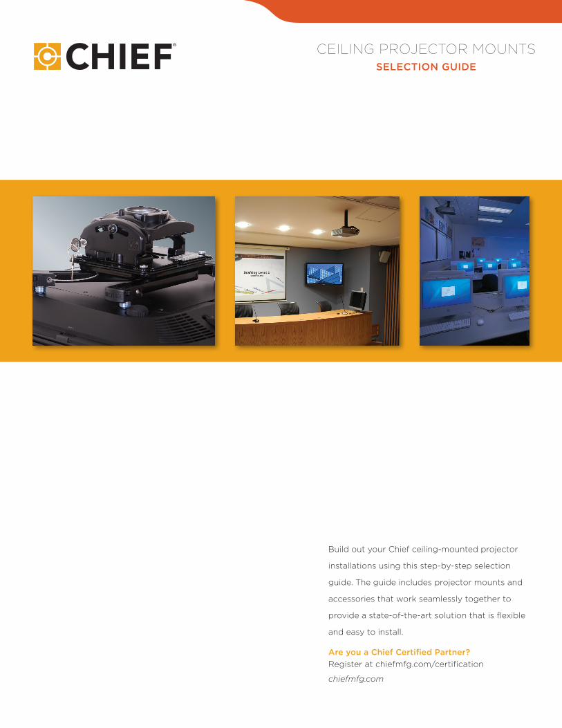
CEILING PROJECTOR MOUNTS SELECTION GUIDE
Build out your Chief ceiling-mounted projector
installations using this step-by-step selection
guide. The guide includes projector mounts and
accessories that work seamlessly together to
provide a state-of-the-art solution that is flexible
and easy to install.
Are you a Chief Certified Partner? Register at chiefmfg.com/certification
chiefmfg.com

CEILING STRUCTURAL SUPPORT
PROJECTOR MOUNTS SELECTION GUIDEW
OO
D J
OIS
T
CO
NC
RE
TE
UN
IST
RU
T
TR
USS
MAX WEIGHT: 500 LBS (227 KG) MAX WEIGHT: 500 LBS (227 KG) MAX WEIGHT: 500 LBS (227 KG)MAX WEIGHT: 250 LBS (113 KG)
CMS115 Ceiling Plate B W S
CMS390/91 Dual Joist Ceiling Plate B
I-B
EA
M
MAX WEIGHT: 250 LBS (113 KG)
CMA360 I-Beam Clamp B
CMA330 Offset Ceiling Plate B
CMA345 Shock-Absorbing Ceiling Plate B
CMA372 Offset Unistrut Adapter B
CMA110 Ceiling Plate B
CMA365 Truss/Pipe Ceiling Adapter B
CMA366 Architectural Spanning Adapter B
VA
ULT
ED
MAX WEIGHT: 500 LBS (227 KG)
CMA395 Angled Ceiling Plate B W
GE
NE
RA
L P
UR
PO
SE MAX WEIGHT: 500 LBS (227 KG)
CMA105 4" Ceiling Plate B
CMA110 8" Ceiling Plate B
CMA115 6" Ceiling Plate B
ACCESSORIES
Concrete – CMA380 Concrete Fastener
Suspended – CMA471 Large Above Tile Enclosure
Suspended – CMA473 XL Above Tile Enclosure
Suspended – CMA472 Low Profile Above Tile Enclosure
Suspended – CMSZ006 0-6" Fully Threaded Column for Ceiling Kits
Suspended – CMA470 Above Tile Enclosure
Suspended - CMS495 Angled Adapter
Power Outlet – PX2W Power Conditioner
STEP 1 CEILING STRUCTURAL SUPPORT
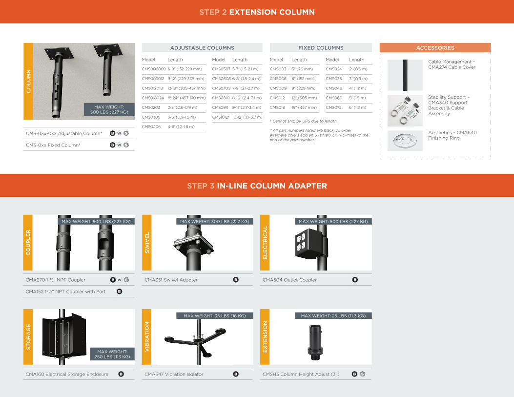
STEP 2 EXTENSION COLUMN
SUSP
EN
DE
D
MAX WEIGHT: 50 LBS (23 KG)
CMS440P Ceiling Kit with PX2W Power W
CMS440 Above Tile Ceiling Kit W
SUSP
EN
DE
D
CMS445P Ceiling Kit with PX2W Power W
CMS445 Replacement Tile Ceiling Kit W
MAX WEIGHT: 50 LBS (23 KG)
CO
LUM
N
MAX WEIGHT: 500 LBS (227 KG)
CMS-0xx-0xx Adjustable Column* B W S
CMS-0xx Fixed Column* B W S
STEP 2 EXTENSION COLUMN
STEP 3 IN-LINE COLUMN ADAPTER
Model Length Model Length
CMS006009 6-9" (152-229 mm) CMS0507 5-7' (1.5-2.1 m)
CMS009012 9-12" (229-305 mm) CMS0608 6-8' (1.8-2.4 m)
CMS012018 12-18" (305-457 mm) CMS0709 7-9' (2.1-2.7 m)
CMS018024 18-24" (457-610 mm) CMS0810 8-10' (2.4-3.1 m)
CMS0203 2-3' (0.6-0.9 m) CMS0911 9-11' (2.7-3.4 m)
CMS0305 3-5' (0.9-1.5 m) CMS1012† 10-12' (3.1-3.7 m)
CMS0406 4-6' (1.2-1.8 m)
ADJUSTABLE COLUMNS
† Cannot ship by UPS due to length. * All part numbers listed are black. To order alternate colors add an S (silver) or W (white) to the end of the part number.
Model Length Model Length
CMS003 3" (76 mm) CMS024 2' (0.6 m)
CMS006 6" (152 mm) CMS036 3' (0.9 m)
CMS009 9" (229 mm) CMS048 4' (1.2 m)
CMS012 12" (305 mm) CMS060 5' (1.5 m)
CMS018 18" (457 mm) CMS072 6' (1.8 m)
FIXED COLUMNS ACCESSORIES
Cable Management – CMA274 Cable Cover
Aesthetics – CMA640 Finishing Ring
Stability Support – CMA340 Support Bracket & Cable Assembly
SWIV
EL
CMA351 Swivel Adapter B
VIB
RA
TIO
N
CMA347 Vibration Isolator B
STO
RA
GE
CMA160 Electrical Storage Enclosure B
ELE
CT
RIC
AL
CMA504 Outlet Coupler B
EX
TE
NSI
ON
CMSH3 Column Height Adjust (3") B S
CO
UP
LER
CMA270 1-½" NPT Coupler
CMA152 1-½" NPT Coupler with Port B
MAX WEIGHT: 500 LBS (227 KG)
SWB
MAX WEIGHT: 500 LBS (227 KG)
MAX WEIGHT: 35 LBS (16 KG)
MAX WEIGHT: 500 LBS (227 KG)
MAX WEIGHT: 25 LBS (11.3 KG)
MAX WEIGHT: 250 LBS (113 KG)
STEP 4 EXTENSION COLUMN (SEE STEP 2)

STEP 5 PROJECTOR MOUNTING SOLUTION
STEP 6 SECURITY ACCESSORIES
STEP 4 EXTENSION COLUMN (SEE STEP 2)
RPA
™ E
LIT
E
MAX WEIGHT: 50 LBS (23 KG)
RPMAxxxx/U Projector Mount B / B W S
RSMAxxxx/U Projector Mount B / B W S
PR
OJE
CTO
R G
UA
RD
PG2 Small Projector Guard B W
PG1 Large Projector Guard B W
PG3 X-Large Projector Guard B W
RPA
™ S
ER
IES
RPAAxxxx/U Projector Mount B / B W S
RSAAxxxx/U Projector Mount B / B W SP
RO
JEC
TOR
LO
CK
PL2A/B/C RPA Small Projector Lock B
PL1A/B/C RPA Large Projector Lock B
HE
AV
Y D
UT
Y
MAX WEIGHT: 250 LBS (113 KG)
VCMU Projector Mount B
MAX WEIGHT: 25 LBS (11.3 KG)
MAX WEIGHT: 50 LBS (23 KG)
MAX WEIGHT: 25 LBS (11.3 KG)
ACCESSORIES
Cable – LC1™ Cable Lock
SSC1™ Screw Cover Kit
800.582.6480 Customer Service

ALL-POINTS SECURITY KEYED SECURITY
Exclusive steel-into-steel locking hardware at all
connection points to protect against theft.
Keyed locking options (A/B/C/D) combined with
All-Points Security steel-into-steel locking hardware
at all connection points to protect against theft.
RPA
™ S
ER
IES
PL
SER
IES*
RPA
™ M
INI S
ER
IES
AC
CE
SSO
RIE
S
RPA
™ M
INI E
LIT
ERPAxxxx Custom Projector Mount B
RPAU Universal Projector Mount B W S
PL1(A/B/C) Projector Lock* B
PL2(A/B/C) Mini Projector Lock* B
RSAxxxx Custom Mini Projector Mount B
RSAU Universal Mini Projector Mount B W S
CMS115 Ceiling Plate B W S
CMS0xx0xx Adjustable Extension Column B W S
CMA152 1-½" to 1-½" NPT Coupler B S
RSM(A/B/C/D)xxxx Custom Mini Projector Mount B
RSM(A/B/C/D)U Universal Mini Projector Mount B W S
MAX WEIGHT: 50 LBS (23 KG)
MAX WEIGHT: 25 LBS (11.3 KG)
*For use with RPAxxxx Series
RPA
™ E
LIT
E
MAX WEIGHT: 50 LBS (23 KG)
RPM(A/B/C/D)xxxx Custom Projector Mount B
RPM(A/B/C/D)U Universal Projector Mount B W S
MAX WEIGHT: 25 LBS (11.3 KG)
BASIC INTERMEDIATE
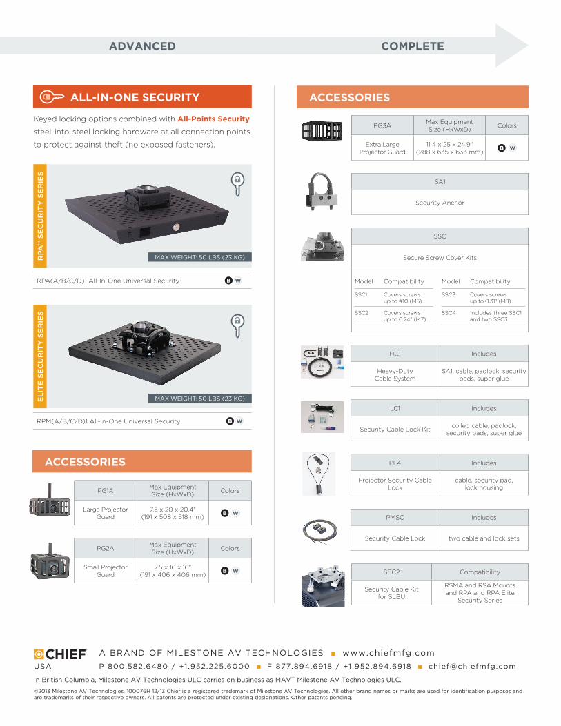
ALL-IN-ONE SECURITY ACCESSORIES
ACCESSORIES
A BRAND OF MILESTONE AV TECHNOLOGIES n www.chiefmfg.com
USA P 800.582.6480 / +1.952.225.6000 n F 877.894.6918 / +1.952.894.6918 n [email protected]
In British Columbia, Milestone AV Technologies ULC carries on business as MAVT Milestone AV Technologies ULC.
©2013 Milestone AV Technologies. 100076H 12/13 Chief is a registered trademark of Milestone AV Technologies. All other brand names or marks are used for identification purposes and are trademarks of their respective owners. All patents are protected under existing designations. Other patents pending.
Keyed locking options combined with All-Points Security
steel-into-steel locking hardware at all connection points
to protect against theft (no exposed fasteners).
RPA
™ S
EC
UR
ITY
SE
RIE
SE
LIT
E S
EC
UR
ITY
SE
RIE
S
RPA(A/B/C/D)1 All-In-One Universal Security B W
RPM(A/B/C/D)1 All-In-One Universal Security B W
MAX WEIGHT: 50 LBS (23 KG)
MAX WEIGHT: 50 LBS (23 KG)
PG3A Max Equipment Size (HxWxD) Colors
Extra Large Projector Guard
11.4 x 25 x 24.9" (288 x 635 x 633 mm)
B W
SA1
Security Anchor
SSC
Secure Screw Cover Kits
Model Compatibility Model Compatibility
SSC1 Covers screws up to #10 (M5)
SSC3 Covers screws up to 0.31" (M8)
SSC2 Covers screws up to 0.24" (M7)
SSC4 Includes three SSC1 and two SSC3
HC1 Includes
Heavy-Duty Cable System
SA1, cable, padlock, security pads, super glue
LC1 Includes
Security Cable Lock Kit coiled cable, padlock, security pads, super glue
PL4 Includes
Projector Security Cable Lock
cable, security pad, lock housing
PMSC Includes
Security Cable Lock two cable and lock sets
SEC2 Compatibility
Security Cable Kit for SLBU
RSMA and RSA Mounts and RPA and RPA Elite
Security Series
ADVANCED COMPLETE
PG1A Max Equipment Size (HxWxD) Colors
Large Projector Guard
7.5 x 20 x 20.4" (191 x 508 x 518 mm)
B W
PG2A Max Equipment Size (HxWxD) Colors
Small Projector Guard
7.5 x 16 x 16" (191 x 406 x 406 mm)
B W