Embed Size (px)
Citation preview
1
Questions, problems, missing parts? Before returning to your retailer, call our customer service department at 1-800-643-0067, 8 a.m. - 6 p.m., EST, Monday - Thursday, 8 a.m. - 5 p.m., EST, Friday.
ATTACH YOUR RECEIPT HERE
Purchase Date _________________________
Harbor Breeze® is a registered trademark of LF, LLC. All Rights Reserved.
PH181053
Español p. 18
H
arbor Breeze
H
arbor Breeze
ITEM #0915543, 1133113
BUILDER’S SERIES CEILING FAN
MODEL #41391, 41690
2
TABLE OF CONTENTS
Package Contents . . . . . . . . . . . . . . . . . . . . . . . . . . . . . . . . . . . . . . . . . . . . . . . . . . . . . . . . . . . . . . . . . 3
Hardware Contents . . . . . . . . . . . . . . . . . . . . . . . . . . . . . . . . . . . . . . . . . . . . . . . . . . . . . . . . . . . . . . . . 4
Safety Information . . . . . . . . . . . . . . . . . . . . . . . . . . . . . . . . . . . . . . . . . . . . . . . . . . . . . . . . . . . . . . . . . 5
Preparation . . . . . . . . . . . . . . . . . . . . . . . . . . . . . . . . . . . . . . . . . . . . . . . . . . . . . . . . . . . . . . . . . . . . . . 6
Initial Installation . . . . . . . . . . . . . . . . . . . . . . . . . . . . . . . . . . . . . . . . . . . . . . . . . . . . . . . . . . . . . . . . . . 6
Wiring . . . . . . . . . . . . . . . . . . . . . . . . . . . . . . . . . . . . . . . . . . . . . . . . . . . . . . . . . . . . . . . . . . . . . . . . . . 9
Final Installation. . . . . . . . . . . . . . . . . . . . . . . . . . . . . . . . . . . . . . . . . . . . . . . . . . . . . . . . . . . . . . . . . . 10
Operating Instructions . . . . . . . . . . . . . . . . . . . . . . . . . . . . . . . . . . . . . . . . . . . . . . . . . . . . . . . . . . . . . 13
Care and Maintenance . . . . . . . . . . . . . . . . . . . . . . . . . . . . . . . . . . . . . . . . . . . . . . . . . . . . . . . . . . . . 14
Troubleshooting . . . . . . . . . . . . . . . . . . . . . . . . . . . . . . . . . . . . . . . . . . . . . . . . . . . . . . . . . . . . . . . . . . 14
Limited Lifetime Warranty . . . . . . . . . . . . . . . . . . . . . . . . . . . . . . . . . . . . . . . . . . . . . . . . . . . . . . . . . . 16
Replacement Parts List . . . . . . . . . . . . . . . . . . . . . . . . . . . . . . . . . . . . . . . . . . . . . . . . . . . . . . . . . . . . 17

3
PACKAGE CONTENTS
PART DESCRIPTION QUANTITYA Motor Housing 1B Upper Mounting Bracket 1C Lower Mounting Bracket (preassembled to Motor [D]) 1D Motor 1E Switch Housing (preassembled to Motor [D]) 1F Light Kit (preassembled to the Switch Housing [E]) 1G Light Pan 1H Bulb 1I Glass Bowl 1J Blade Arm 5K Blade 5L Lower Bracket Screw (preassembled to Lower Mounting Bracket [C]) 4M Switch Housing Screws (preassembled to Light Pan [G]) 3N Motor Screw (preassembled to Motor [D]) 10 O Motor Housing Screw (preassembled to Upper Mounting Bracket [B]) 4
A
B
C
D
E
F
M
G
H
IJ
K
L
N
O

4
HARDWARE CONTENTS (shown actual size)
Wire ConnectorQty. 3 + 1 extra
Blade ScrewQty. 15 + 1 extra
Blade WasherQty. 15 + 1 extra
Pull Chain Extension Qty. 2
Motor Screw1 extra
AA BB CC DD
H
arbor Breeze
H
arbor Breeze
XX
5
SAFETY INFORMATIONPlease read and understand this entire manual before attempting to assemble, operate or install the product.• Before you begin installing the fan, disconnect the power by removing fuses or turning off the circuit
breakers.• Make sure all electrical connections comply with local codes, ordinances, the National Electrical
Code and ANSI/NFPA 70-199. Hire a qualified electrician or consult a do-it-yourself wiring handbook if you are unfamiliar with installing electrical wiring.
• Make sure the installation site you choose allows a minimum clearance of 7 ft. from the blades to the floor and at least 30 in. from the end of the blades to any obstruction.
• The net weight of this fan is: 14.11 lbs.
DANGER: When using an existing outlet box, make sure the outlet box is securely attached to the building structure and can support the full weight of the fan. Failure to do this can result in serious injury or death. The stability of the outlet box is essential in minimizing wobble and noise in the fan after installation is complete.
WARNING: To avoid personal injury, the use of gloves may be necessary while handling fan parts with sharp edges.
WARNING: To reduce the risk of fire, electric shock or personal injury, mount the fan to an outlet box marked “ACCEPTABLE FOR FAN SUPPORT” and use the mounting screws provided with the outlet box. Most outlet boxes commonly used for the support of lighting fixtures are not acceptable for fan support and may need to be replaced. Consult a qualified electrician if in doubt. Secure the outlet box directly to the building structure. The outlet box and its support must be able to support the moving weight of the fan (at least 35 lbs.).
WARNING: To reduce the risk of fire, electric shock or personal injury, wire connectors provided with this fan are designed to accept only one 12-gauge house wire and two lead wires from the fan. If your house wire is larger than 12 gauges and/or there is more than one house wire to connect to the two fan lead wires, consult an electrician for the proper size wire connectors to use.
WARNING: To reduce the risk of fire or electric shock, do not use the fan with any solid-state speed-control device or control the fan speed with a full-range dimmer switch.
WARNING: To reduce the risk of fire, electric shock or personal injury, do not bend the blade arms when installing them, balancing the blades or cleaning the fan. Do not insert objects between the rotating fan blades.
WARNING: To reduce the risk of personal injury, use only parts provided with this fan. The use of parts OTHER than those provided with this fan will void the warranty.

6
SAFETY INFORMATIONCAUTION: Read all instructions and safety information before installing your new fan. Review the accompanying assembly diagrams.
CAUTION: Be sure the outlet box is properly grounded or that a ground (green or bare) wire is present.
CAUTION: Carefully check all screws, bolts and nuts on the fan motor assembly to ensure they are secured.CAUTION: This equipment has been tested and found to comply with the limits for a Class B digital device, pursuant to Part 15 of the FCC Rules. These limits are designed to provide reasonable protection against harmful interference in a residential installation. This equipment generates, uses and can radiate radio frequency energy and, if not installed and used in accordance with the instructions, may cause harmful interference to radio communications. However, there is no guarantee that interference will not occur in a particular installation. If this equipment does cause harmful interference to radio or television reception, which can be determined by turning the equipment off and on, the user is encouraged to try to correct the interference by one or more of the following measures:--Reorient or relocate the receiving antenna.--Increase the separation between the equipment and receiver--Connect the equipment into and outlet on a circuit different from that to which the receiver is connected.--Consult the dealer or an experienced radio/TV technician for help.Please note changes or modifications not expressly approved by the party responsible for compliance could void the user’s authority to operate the equipment.
PREPARATION
Before beginning the assembly of this product, ensure that all parts are present. Compare all parts with the package contents list and hardware contents list. If any part is missing or damaged, do not attempt to assemble the product. Estimated Assembly Time: 120 minutesTools Required for Assembly (not included): Electrical Tape, Phillips Screwdriver, Pliers, Safety Glasses, Step Ladder, Wire Cutters and Wire StrippersHelpful Tools (not included): AC Tester Light, Tape Measure and Wiring Handbook
INITIAL INSTALLATION1. Turn off the circuit breakers and the wall switch to the
fan supply line leads.
DANGER: Failure to disconnect the power supply prior to installation may result in serious injury or death.
1
7
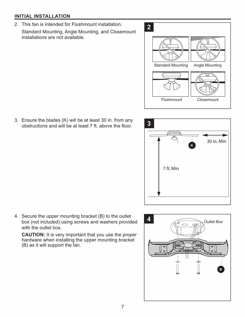
INITIAL INSTALLATION2. This fan is intended for Flushmount installation.
Standard Mounting, Angle Mounting, and Closemount installations are not available.
3. Ensure the blades (K) will be at least 30 in. from any obstructions and will be at least 7 ft. above the floor.
7 ft. Min
30 in. Min
4. Secure the upper mounting bracket (B) to the outlet box (not included) using screws and washers provided with the outlet box.CAUTION: It is very important that you use the proper hardware when installing the upper mounting bracket (B) as it will support the fan.
3
Outlet Box
K
B
4
2
Standard Mounting
Flushmount Closemount
Angle Mounting

8
INITIAL INSTALLATION5. Remove the lower bracket screws (L) from underneath
the lower mounting bracket (C).
6. Place one tab of the lower mounting bracket (C) into a slot in the upper mounting bracket (B), then slide the second tab of the lower mounting bracket (C) into the second slot on the upper mounting bracket (B) until all four holes are in alignment.
7. Re-install the previously removed lower bracket screws (L) to secure the lower mounting bracket (C) to the upper mounting bracket (B).
L
C
6
7
B
C
B
C L
Slot
5
9
WIRING
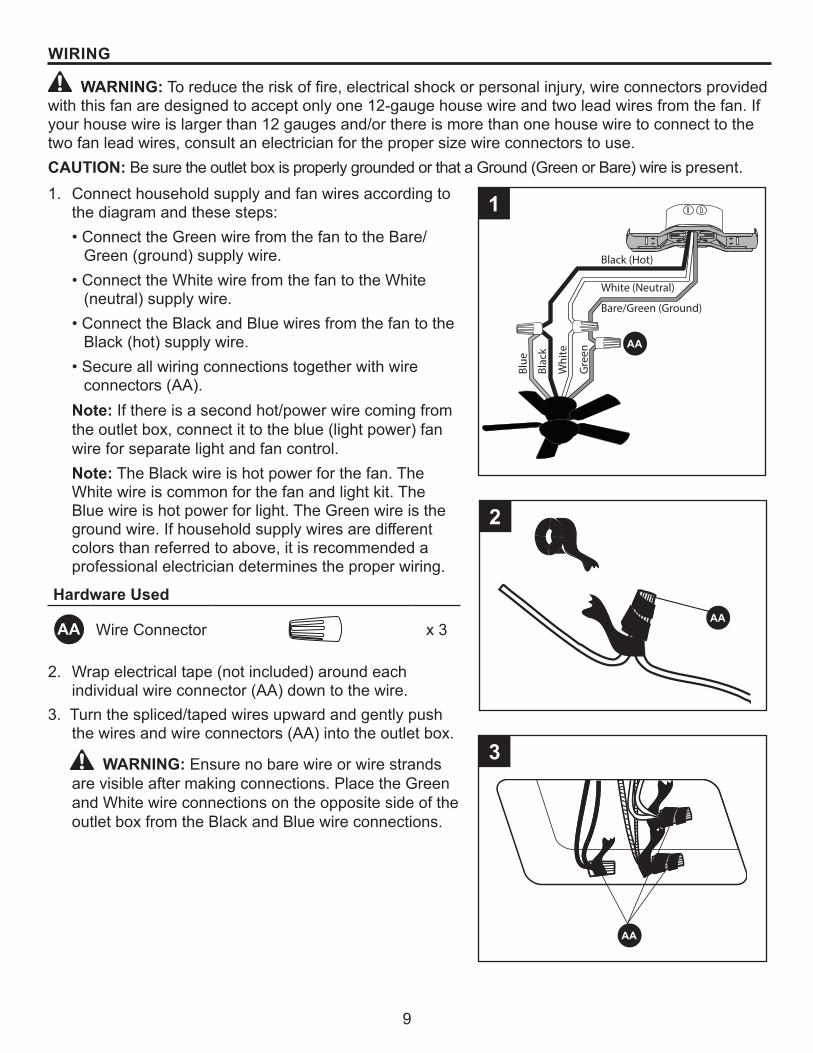
WARNING: To reduce the risk of fire, electrical shock or personal injury, wire connectors provided with this fan are designed to accept only one 12-gauge house wire and two lead wires from the fan. If your house wire is larger than 12 gauges and/or there is more than one house wire to connect to the two fan lead wires, consult an electrician for the proper size wire connectors to use.CAUTION: Be sure the outlet box is properly grounded or that a Ground (Green or Bare) wire is present.1. Connect household supply and fan wires according to
the diagram and these steps:• Connect the Green wire from the fan to the Bare/
Green (ground) supply wire. • Connect the White wire from the fan to the White
(neutral) supply wire. • Connect the Black and Blue wires from the fan to the
Black (hot) supply wire. • Secure all wiring connections together with wire
connectors (AA).Note: If there is a second hot/power wire coming from the outlet box, connect it to the blue (light power) fan wire for separate light and fan control.Note: The Black wire is hot power for the fan. The White wire is common for the fan and light kit. The Blue wire is hot power for light. The Green wire is the ground wire. If household supply wires are different colors than referred to above, it is recommended a professional electrician determines the proper wiring.
Hardware Used
AA Wire Connector x 3
2. Wrap electrical tape (not included) around each individual wire connector (AA) down to the wire.
3. Turn the spliced/taped wires upward and gently push the wires and wire connectors (AA) into the outlet box.
WARNING: Ensure no bare wire or wire strands are visible after making connections. Place the Green and White wire connections on the opposite side of the outlet box from the Black and Blue wire connections.
1
3
AA
AA
AA
2
Black (Hot)
White (Neutral)
Bare/Green (Ground)
Blac
k
Blue
Whi
te
Gre
en
10
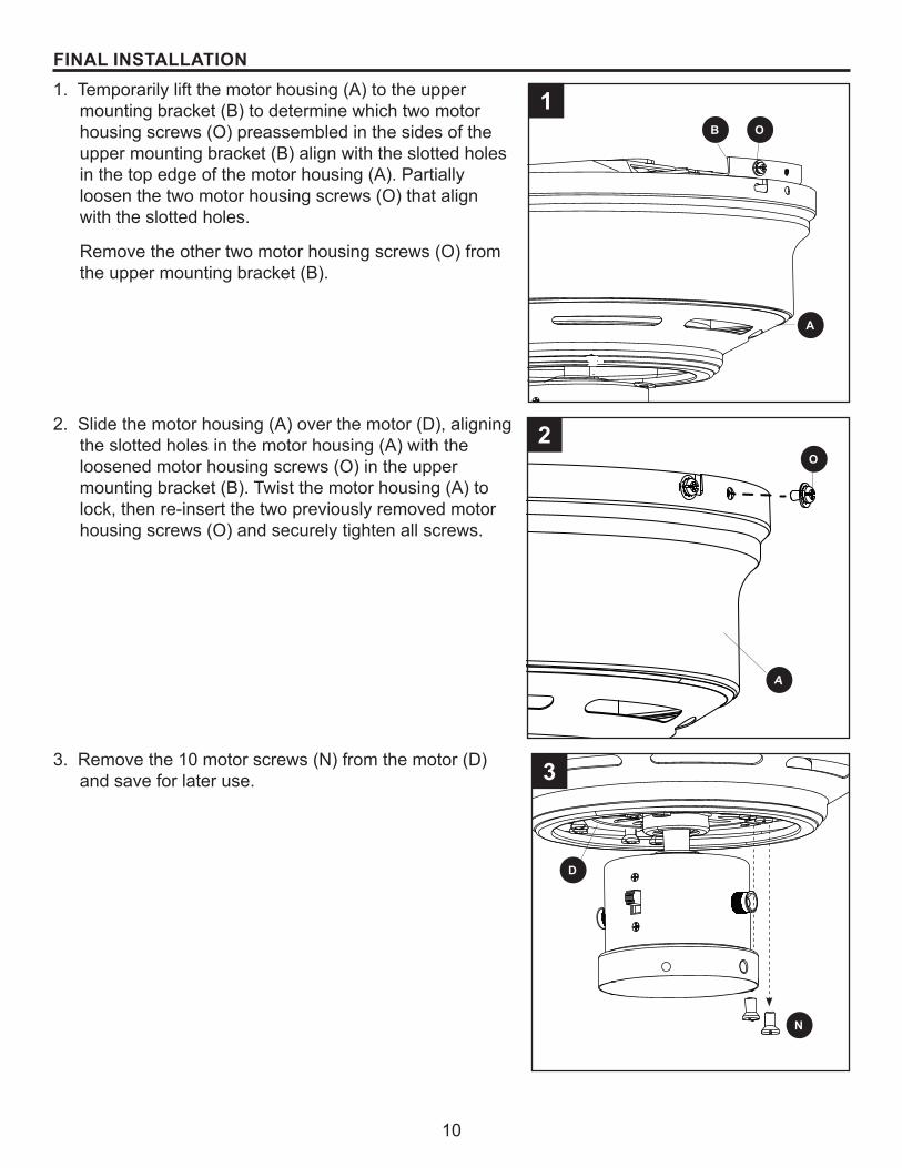
FINAL INSTALLATION1. Temporarily lift the motor housing (A) to the upper
mounting bracket (B) to determine which two motor housing screws (O) preassembled in the sides of the upper mounting bracket (B) align with the slotted holes in the top edge of the motor housing (A). Partially loosen the two motor housing screws (O) that align with the slotted holes.
Remove the other two motor housing screws (O) from the upper mounting bracket (B).
2. Slide the motor housing (A) over the motor (D), aligning the slotted holes in the motor housing (A) with the loosened motor housing screws (O) in the upper mounting bracket (B). Twist the motor housing (A) to lock, then re-insert the two previously removed motor housing screws (O) and securely tighten all screws.
3. Remove the 10 motor screws (N) from the motor (D) and save for later use.
B
O
A
O
A
1
2
3
D
N
11
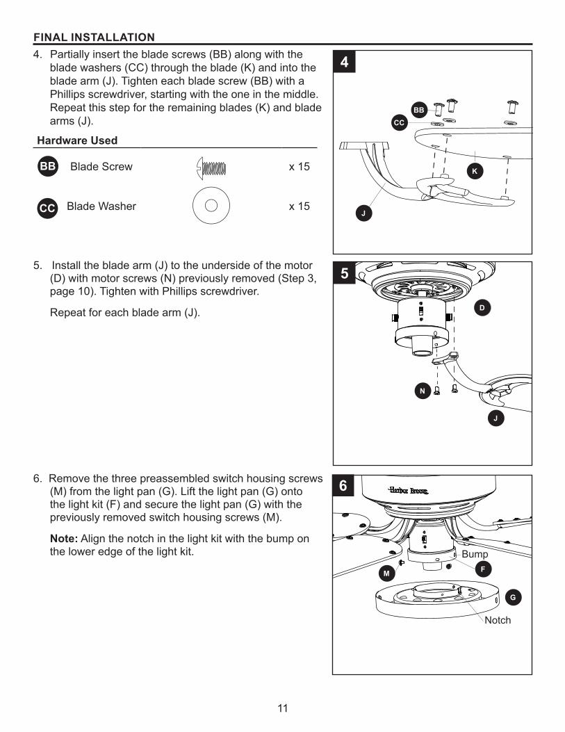
FINAL INSTALLATION4. Partially insert the blade screws (BB) along with the
blade washers (CC) through the blade (K) and into the blade arm (J). Tighten each blade screw (BB) with a Phillips screwdriver, starting with the one in the middle. Repeat this step for the remaining blades (K) and blade arms (J).
Hardware Used
BB Blade Screw x 15
Blade Washer x 15
5. Install the blade arm (J) to the underside of the motor (D) with motor screws (N) previously removed (Step 3, page 10). Tighten with Phillips screwdriver.
Repeat for each blade arm (J).
6. Remove the three preassembled switch housing screws (M) from the light pan (G). Lift the light pan (G) onto the light kit (F) and secure the light pan (G) with the previously removed switch housing screws (M).
Note: Align the notch in the light kit with the bump on the lower edge of the light kit.
4
5
BBCC
K
J
J
N
D
6
G
M F
CC
Bump
Notch
12
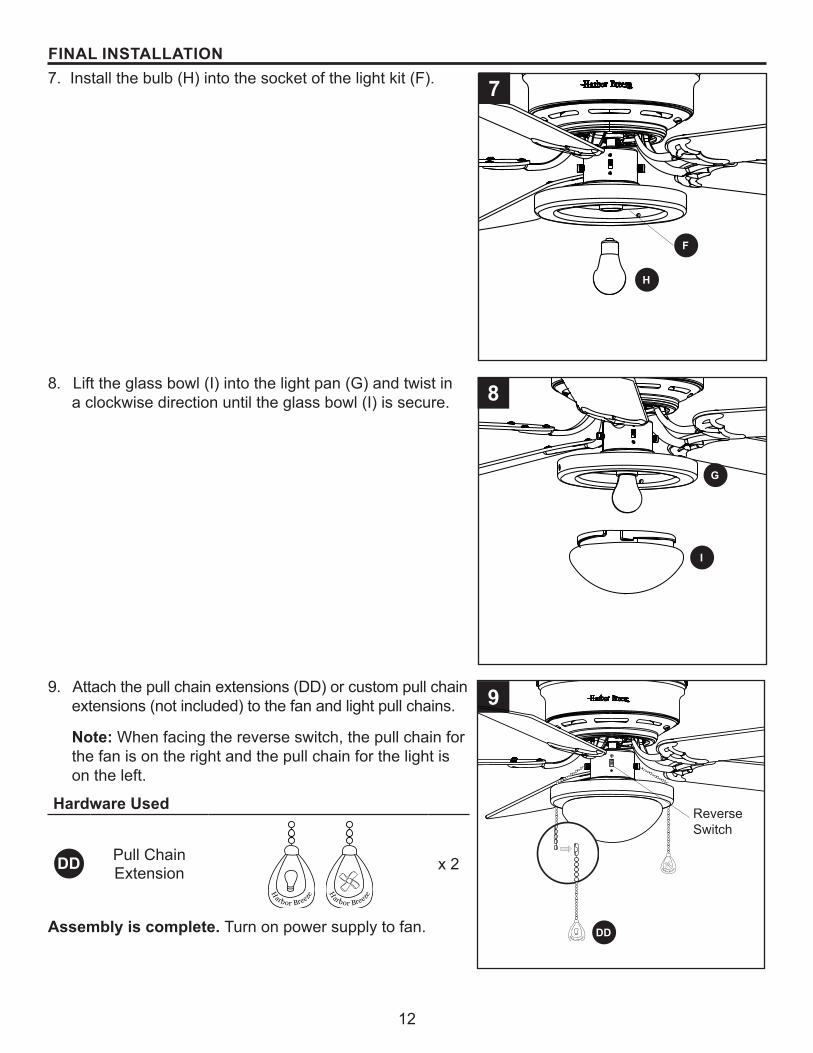
FINAL INSTALLATION7. Install the bulb (H) into the socket of the light kit (F).
8. Lift the glass bowl (I) into the light pan (G) and twist in a clockwise direction until the glass bowl (I) is secure.
9. Attach the pull chain extensions (DD) or custom pull chain extensions (not included) to the fan and light pull chains.
Note:� When facing the reverse switch, the pull chain for the fan is on the right and the pull chain for the light is on the left.
Hardware Used
DD Pull Chain Extension x 2
Assembly is complete. Turn on power supply to fan.
9
Reverse Switch
H
arb or Breeze
H
arbor Breeze
DD
I
H
F
G
H
arbor Breeze
H
arbor Breeze
8
7
13
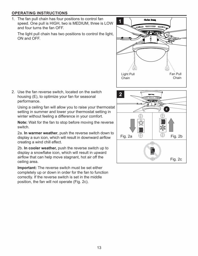
OPERATING INSTRUCTIONS1. The fan pull chain has four positions to control fan
speed. One pull is HIGH, two is MEDIUM, three is LOW and four turns the fan OFF. The light pull chain has two positions to control the light, ON and OFF.
H
arbor Breeze H
arb or Breeze
2. Use the fan reverse switch, located on the switch housing (E), to optimize your fan for seasonal performance.Using a ceiling fan will allow you to raise your thermostat setting in summer and lower your thermostat setting in winter without feeling a difference in your comfort.Note:� Wait for the fan to stop before moving the reverse switch.2a. In warmer weather, push the reverse switch down to display a sun icon, which will result in downward airflow creating a wind chill effect. 2b. In cooler weather, push the reverse switch up to display a snowflake icon, which will result in upward airflow that can help move stagnant, hot air off the ceiling area. Important:� The reverse switch must be set either completely up or down in order for the fan to function correctly. If the reverse switch is set in the middle position, the fan will not operate (Fig. 2c).
Fig. 2a Fig. 2b
Fig. 2c
2
1
Fan Pull Chain
Light Pull Chain
E
14
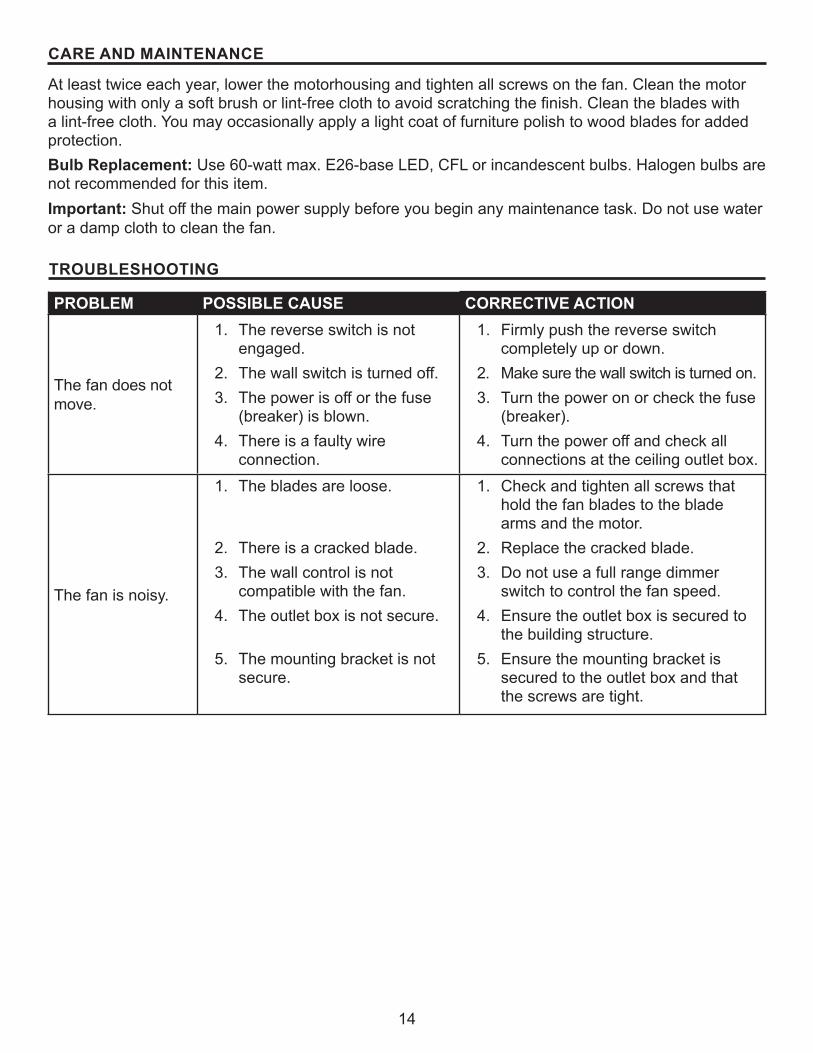
CARE AND MAINTENANCE
At least twice each year, lower the motorhousing and tighten all screws on the fan. Clean the motor housing with only a soft brush or lint-free cloth to avoid scratching the finish. Clean the blades with a lint-free cloth. You may occasionally apply a light coat of furniture polish to wood blades for added protection.Bulb Replacement: Use 60-watt max. E26-base LED, CFL or incandescent bulbs. Halogen bulbs are not recommended for this item.Important: Shut off the main power supply before you begin any maintenance task. Do not use water or a damp cloth to clean the fan. TROUBLESHOOTING
PROBLEM POSSIBLE CAUSE CORRECTIVE ACTION
The fan does not move.
1. The reverse switch is not engaged.
2. The wall switch is turned off.3. The power is off or the fuse
(breaker) is blown.4. There is a faulty wire
connection.
1. Firmly push the reverse switch completely up or down.
2. Make sure the wall switch is turned on.3. Turn the power on or check the fuse
(breaker).4. Turn the power off and check all
connections at the ceiling outlet box.
The fan is noisy.
1. The blades are loose.
2. There is a cracked blade.3. The wall control is not
compatible with the fan.4. The outlet box is not secure.
5. The mounting bracket is not secure.
1. Check and tighten all screws that hold the fan blades to the blade arms and the motor.
2. Replace the cracked blade.3. Do not use a full range dimmer
switch to control the fan speed.4. Ensure the outlet box is secured to
the building structure.5. Ensure the mounting bracket is
secured to the outlet box and that the screws are tight.
15
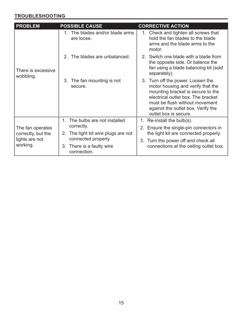
TROUBLESHOOTING
PROBLEM POSSIBLE CAUSE CORRECTIVE ACTION
There is excessive wobbling.
1. The blades and/or blade arms are loose.
2. The blades are unbalanced.
3. The fan mounting is not secure.
1. Check and tighten all screws that hold the fan blades to the blade arms and the blade arms to the motor.
2. Switch one blade with a blade from the opposite side. Or balance the fan using a blade balancing kit (sold separately).
3. Turn off the power. Loosen the motor housing and verify that the mounting bracket is secure to the electrical outlet box. The bracket must be flush without movement against the outlet box. Verify the outlet box is secure.
The fan operates correctly, but the lights are not working.
1. The bulbs are not installed correctly.
2. The light kit wire plugs are not connected properly.
3. There is a faulty wire connection.
1. Re-install the bulb(s).2. Ensure the single-pin connectors in
the light kit are connected properly.3. Turn the power off and check all
connections at the ceiling outlet box.
16
LIMITED LIFETIME WARRANTY
The manufacturer warrants this fan to be free from defects in workmanship and materials present at time of shipment from the factory for a lifetime from the date of purchase by the original purchaser. The retailer also warrants that all other fan parts, excluding any glass or plastic blades, to be free from defects in workmanship and material at the time of shipment from the factory for a period of one year after the date of purchase by the original purchaser. The manufacturer agrees to correct such defects without charge or at its option replace the ceiling fan with a comparable or superior model.To obtain warranty service, present a copy of the receipt as proof of purchase. All costs of removing and reinstalling the product are your responsibility. Any damage to any part such as by accident or misuse or improper installation or by affixing any accessories, is not covered by this warranty. The manufacturer assumes no responsibility whatsoever for fan installation during the limited lifetime warranty. Any service performed by an unauthorized person will render the warranty invalid.Due to varying climate conditions, this warranty does not cover any changes in brass finish, including rusting, pitting, corroding, tarnishing or peeling. Brass finishes of this type give their longest useful life when protected from varying weather conditions. Any glass provided with this fan is not covered by the warranty.Any replacement of defective parts from the ceiling fan must be reported within the first year from the date of purchase. For the balance of the warranty, call our customer service department for return authorization and shipping instructions so that we may repair or replace the ceiling fan. Any fan or parts returned improperly is the sole responsibility of the purchaser. There is no other expressed warranty. The manufacturer disclaims any and all warranties. The duration of any implied warranty which cannot be disclaimed is limited to the time period as specified in the expressed warranty. The manufacturer shall not be liable for incidental, consequential, or special damages arising out of or in connection with product use or performance except as may otherwise be accorded by law. This warranty gives specific legal rights, and you may also have other rights which vary from state to state.This warranty supersedes all prior warranties.Note:� A small amount of “wobble” is normal and should not be considered a defect.
17Printed in China
PART DESCRIPTION 0915543PART #
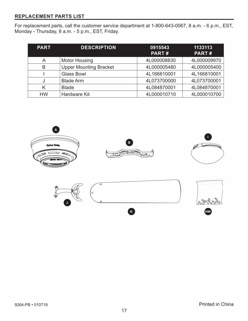
1133113PART #
A Motor Housing 4L000008830 4L000009970B Upper Mounting Bracket 4L000005480 4L000005400I Glass Bowl 4L166810001 4L166810001J Blade Arm 4L073700000 4L073700001K Blade 4L084870001 4L084870001
HW Hardware Kit 4L000010710 4L000010700
9264-PB • 010719
BI
A
J
HWK
REPLACEMENT PARTS LIST
For replacement parts, call the customer service department at 1-800-643-0067, 8 a.m. - 6 p.m., EST, Monday - Thursday, 8 a.m. - 5 p.m., EST, Friday.