Embed Size (px)
Citation preview
1
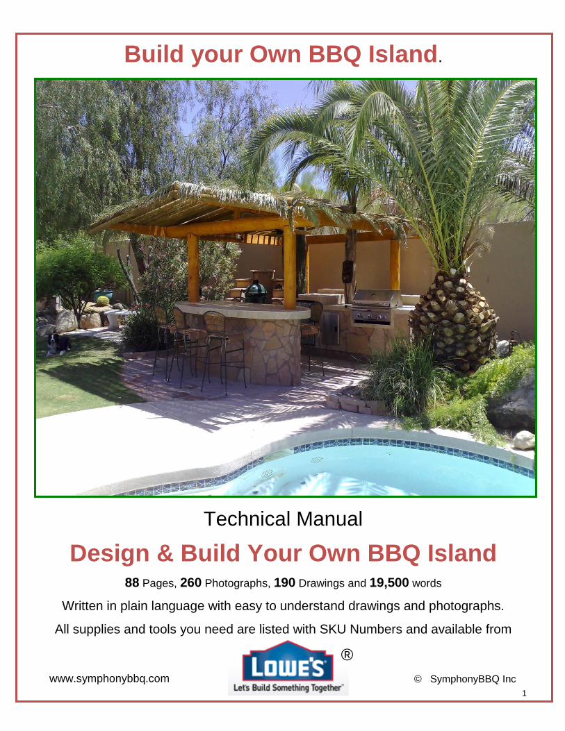
Build your Own BBQ Island.
Technical Manual
Design & Build Your Own BBQ Island
88 Pages, 260 Photographs, 190 Drawings and 19,500 words
Written in plain language with easy to understand drawings and photographs.
All supplies and tools you need are listed with SKU Numbers and available from
®
www.symphonybbq.com © SymphonyBBQ Inc
2
Do it Yourself Build a BBQ Island
Michael J Davey Scottsdale, AZ
This manual is protected under Copyright Law of the
United States of America and the United Kingdom 2007
No part of this manual, including but not limited to, photographs, pictures, diagrams or drawings may be reproduced or copied or transferred electronically to third parties without the express
written permission of the author.
This copy of the manual is for the sole use of the original purchaser and a License to use the information contained herein is granted to the original purchaser by the author.
Any copying, retransmission editing or distribution without the express written permission of the author will terminate the License and all copies in the possession or distributed by the purchaser
will be considered un-licensed and therefore in infringement of the Copyright law.
Furthermore, if the purchaser wishes to use the information contained herein, for the creation or supplement of a business whereby BBQ Islands would be a part of that business, then the
purchaser is not permitted to use or distribute any of the enclosed information within that business without the express written permission of the author.
Michael J Davey [email protected]
602 432 7878
Scottsdale, AZ Feb 2017
3
Build Your Own BBQ Island.
The following manual describes how an average DIY guy can build a BBQ Island in a few days, and save 100’s even 1000’s of $$ in the process. A typical BBQ Island is constructed of steel studding and Hardibacker cement board. The average cost of materials ranges from around $250 - $300 excluding the grill unit and accessories and the cost of tiles (these can vary so much, depending upon personal choice). A typical “Parts-List” and costing are detailed at the end of this manual. The units I describe in this manual are built around a normal “stand-alone” BBQ unit as purchased in any typical gardening center like Lowes, etc. These units are far cheaper than the professional slide-in units and I guess the reason you’re reading this is because you want to save money. I have painstakingly described every step of the process from what materials you need, the tools required and where to get them, plus numerous detailed methods of each process, plus tricks to help you. Please, read the full manual before you commence your project, familiarize yourself with, the considerations, decisions and methods of construction so as to prepare yourself for the “next-stage” while working on the current stage. If you can find the grill unit I’ve used in my examples, my measurements are pretty accurate, and if followed will allow you to build a beautiful island. If you use an alternative grill, read the manual fully to understand the theory and follow the instructions on how to make the measurements, how to make allowances for clearance and note the numerous tricks and considerations. Remember this manual describes Techniques, Methods and Construction Pointers. You will be able to exactly copy my measurements and produce the islands described herein if you can find the grills I use, but BBQ manufacturers are continually changing their product line and new units appear all the time. Just follow the guidelines and you’ll be able to construct a BBQ Island around any chosen grill and it will give you years of enjoyment and significantly increase the value of your home. Stuccoing and Tiling of the finished unit is not detailed in this manual although detailed considerations regarding allowing for tiling or Stuccoing are described. One final word…. Safety…. Stand alone units are not meant to be “boxed-in”, unless there is adequate ventilation to allow for the exit of leaky gas joints of gas bottles. The islands MUST have a lower venting area to allow for any gas to be vented away and not build up inside the island. As gas is heavier than air, the vent must be as low down as possible. I can’t tell you where to put this vent for every island, but look at my island examples and you’ll see it is an easy task to work out. (See Safety Vent Installation – at the end of this chapter (Island One), for more detail.)
Due to differing conditions, tools, and individual skills, The author assumes no responsibility for any damages, injuries suffered, or losses incurred as a result of attempting to replicate this project. I always recommend that you check with
authorities to ensure that any home improvement project complies with all applicable local codes and regulations. Always read and observe all of the safety precautions provided by any tool or equipment manufacturer, and follow all
accepted safety procedures.
The writer of this manual cannot be responsible for any mistakes in construction, or any accidents caused by inadequate ventilation used in the design of your island. This manual is meant as a guideline for you to construct your
island – all measurements are yours, - measure, check then cut and build.
You can get everything you need at Lowes ® - I’ve listed all the SKU numbers throughout this manual and give a list at the end which shows approximate costs of the project.
4
DIY – Build your own Barbeque Island.
FACTS: Lawn and garden sales at retailers jumped from an estimated $26.6 billion in 1997 to $39.6 billion last year, according to a
recent Harris Interactive poll conducted for the National Gardening Association in Burlington, Vt. Much of this activity is connected to the buoyant housing and mortgage markets, and to the post-Sept. 11, 2001, cocooning phenomenon, but the numbers suggest a fundamental shift in how we view and use the yard. Homeowners are no longer willing to step out onto a 9-by-12 concrete patio, housing a freestanding charcoal barbeque overlooking a weedy lawn. Spending over five figures on a trophy outdoor kitchen is now an acceptable practice and an addition to increase a property’s value, an investment that is now as acceptable as installing a new interior kitchen or modernized bathrooms. Outdoor Kitchens or Barbeques are relatively easy for the DIY enthusiast to complete. By spending a few hundred dollars using basic materials, you can construct and install an Outdoor Kitchen Island, incorporating a Barbeque that will add thousands to you property value. By following and adapting the instructions below and studying the procedures, you should be able to complete your island over a long weekend – then, turn it into a business. Barbeque Islands sell for around $1200 - $8000.
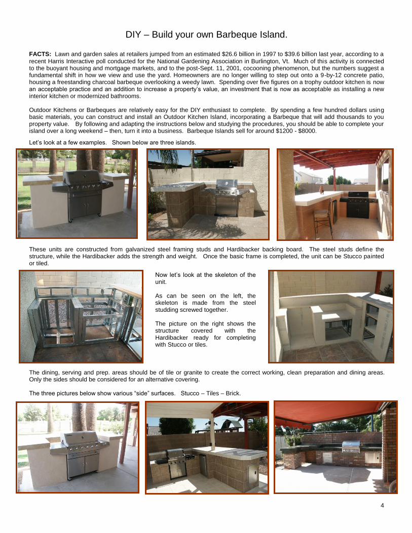
Let’s look at a few examples. Shown below are three islands.
These units are constructed from galvanized steel framing studs and Hardibacker backing board. The steel studs define the structure, while the Hardibacker adds the strength and weight. Once the basic frame is completed, the unit can be Stucco painted or tiled.
Now let’s look at the skeleton of the unit. As can be seen on the left, the skeleton is made from the steel studding screwed together. The picture on the right shows the structure covered with the Hardibacker ready for completing with Stucco or tiles.
The dining, serving and prep. areas should be of tile or granite to create the correct working, clean preparation and dining areas. Only the sides should be considered for an alternative covering. The three pictures below show various “side” surfaces. Stucco – Tiles – Brick.
Barbeque 1
Barbeque 2
Barbeque 3
Barbeque Studding
Barbeque Hardibacker
Barbeque Stucco
Barbeque Tiles
Barbeque Brick
5
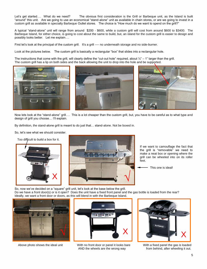
Let’s get started…. What do we need? The obvious first consideration is the Grill or Barbeque unit, as the Island is built “around” this unit. Are we going to use an economical “stand-alone” unit as available in chain stores, or are we going to invest in a custom grill as available in specialty Barbeque Outlet stores. The choice is “How much do we want to spend on the grill?” A typical “stand-alone” unit will range from around $200 - $600, while a custom grill will cost from around $600 to $3400. The Barbeque Island, for either choice, is going to cost about the same to build, but, an island for the custom grill is easier to design and possibly looks better. Let me explain…. First let’s look at the principal of the custom grill. It’s a grill ---- no underneath storage and no side-burner. Look at the pictures below. The custom grill is basically a rectangular “box” that slides into a rectangular hole. The instructions that come with the grill, will clearly define the “cut-out hole” required, about ½” – 1” larger than the grill. The custom grill has a lip on both sides and the back allowing the unit to drop into the hole and be supported.
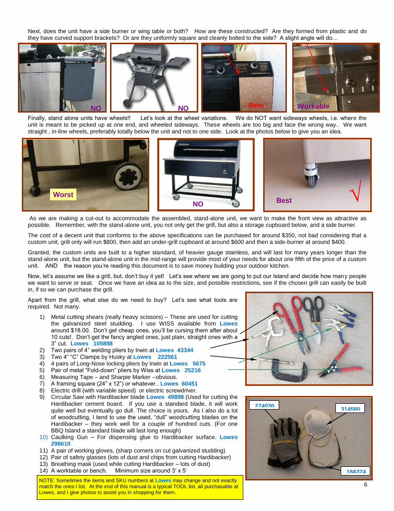
Now lets look at the “stand-alone” grill…. This is a lot cheaper than the custom grill, but, you have to be careful as to what type and design of grill you choose… I’ll explain. By definition, the stand-alone grill is meant to do just that… stand-alone. Not be boxed in. So, let’s see what we should consider. Too difficult to build a box for it.
If we want to camouflage the fact that the grill is “removable” we need to make a neat box or opening where the grill can be wheeled into on its roller feet. This one is ideal!
So, now we’ve decided on a “square” grill unit, let’s look at the base below the grill. Do we have a front door(s) or is it open? Does the unit have a fixed front panel and the gas bottle is loaded from the rear? Ideally, we want a front door or doors, as this will blend in with the Barbeque Island. Above photo shows the ideal unit With no front door or panel it looks bare With a fixed panel the gas is loaded AND the wheels are the wrong way from behind, after wheeling it out.
Barbeque Custom Grill
Custom Hole Drawing
Barbeque Support Lip
Square bottom grill
Doors below unit
√
√
√
√
X X
X
6
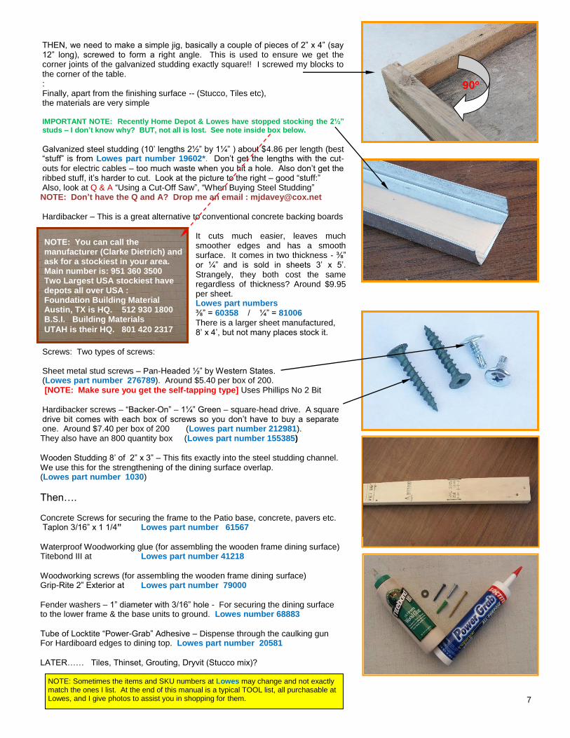
Next, does the unit have a side burner or wing table or both? How are these constructed? Are they formed from plastic and do they have curved support brackets? Or are they uniformly square and cleanly bolted to the side? A slight angle will do… Finally, stand alone units have wheels!! Let’s look at the wheel variations. We do NOT want sideways wheels, i.e. where the unit is meant to be picked up at one end, and wheeled sideways. These wheels are too big and face the wrong way.. We want straight , in-line wheels, preferably totally below the unit and not to one side. Look at the photos below to give you an idea. As we are making a cut-out to accommodate the assembled, stand-alone unit, we want to make the front view as attractive as possible. Remember, with the stand-alone unit, you not only get the grill, but also a storage cupboard below, and a side burner.
The cost of a decent unit that conforms to the above specifications can be purchased for around $350, not bad considering that a custom unit, grill only will run $800, then add an under-grill cupboard at around $600 and then a side-burner at around $400.
Granted, the custom units are built to a higher standard, of heavier gauge stainless, and will last for many years longer than the stand-alone unit, but the stand-alone unit in the mid-range will provide most of your needs for about one fifth of the price of a custom unit. AND the reason you’re reading this document is to save money building your outdoor kitchen.
Now, let’s assume we like a grill, but, don’t buy it yet! Let’s see where we are going to put our Island and decide how many people we want to serve or seat. Once we have an idea as to the size, and possible restrictions, see if the chosen grill can easily be built in, if so we can purchase the grill.
Apart from the grill, what else do we need to buy? Let’s see what tools are required. Not many.
1) Metal cutting shears (really heavy scissors) – These are used for cutting the galvanized steel studding. I use WISS available from Lowes
around $18.00. Don’t get cheap ones, you’ll be cursing them after about 10 cuts!. Don’t get the fancy angled ones, just plain, straight ones with a 3” cut. Lowes 105898
2) Two pairs of 4” welding pliers by Irwin at Lowes 43344 3) Two 4” “C” Clamps by Husky at Lowes 222561 4) 4 pairs of Long-Nose locking pliers by Irwin at Lowes 5675 5) Pair of metal “Fold-down” pliers by Wiss at Lowes 25216
6) Measuring Tape – and Sharpie Marker --obvious. 7) A framing square (24” x 12”) or whatever.. Lowes 60451
8) Electric drill (with variable speed) or electric screwdriver. 9) Circular Saw with Hardibacker blade Lowes 49898 (Used for cutting the
Hardibacker cement board. If you use a standard blade, it will work quite well but eventually go dull. The choice is yours. As I also do a lot of woodcutting, I tend to use the used, “dull” woodcutting blades on the Hardibacker – they work well for a couple of hundred cuts. (For one BBQ Island a standard blade will last long enough)
10) Caulking Gun – For dispensing glue to Hardibacker surface. Lowes 298610
11) A pair of working gloves, (sharp corners on cut galvanized studding) 12) Pair of safety glasses (lots of dust and chips from cutting Hardibacker) 13) Breathing mask (used while cutting Hardibacker – lots of dust) 14) A worktable or bench. Minimum size around 3’ x 5’
Tools
Best
Workable Best NO
Worst
NO
NO
NO
√
√
274030
166374
314580
NOTE: Sometimes the items and SKU numbers at Lowes may change and not exactly match the ones I list. At the end of this manual is a typical TOOL list, all purchasable at Lowes, and I give photos to assist you in shopping for them.
7
THEN, we need to make a simple jig, basically a couple of pieces of 2” x 4” (say 12” long), screwed to form a right angle. This is used to ensure we get the corner joints of the galvanized studding exactly square!! I screwed my blocks to the corner of the table. : Finally, apart from the finishing surface -- (Stucco, Tiles etc), the materials are very simple IMPORTANT NOTE: Recently Home Depot & Lowes have stopped stocking the 2½” studs – I don’t know why? BUT, not all is lost. See note inside box below.
Galvanized steel studding (10’ lengths 2½” by 1¼” ) about $4.86 per length (best “stuff” is from Lowes part number 19602*. Don’t get the lengths with the cut-
outs for electric cables – too much waste when you hit a hole. Also don’t get the ribbed stuff, it’s harder to cut. Look at the picture to the right – good “stuff:” Also, look at Q & A “Using a Cut-Off Saw”, “When Buying Steel Studding” NOTE: Don’t have the Q and A? Drop me an email : [email protected]
Hardibacker – This is a great alternative to conventional concrete backing boards
It cuts much easier, leaves much smoother edges and has a smooth surface. It comes in two thickness - ⅜” or ¼” and is sold in sheets 3’ x 5’. Strangely, they both cost the same regardless of thickness? Around $9.95 per sheet. Lowes part numbers ⅜” = 60358 / ¼” = 81006
There is a larger sheet manufactured, 8’ x 4’, but not many places stock it.
Screws: Two types of screws: Sheet metal stud screws – Pan-Headed ½” by Western States. (Lowes part number 276789). Around $5.40 per box of 200. [NOTE: Make sure you get the self-tapping type] Uses Phillips No 2 Bit
Hardibacker screws – “Backer-On” – 1¼” Green – square-head drive. A square drive bit comes with each box of screws so you don’t have to buy a separate one. Around $7.40 per box of 200 (Lowes part number 212981). They also have an 800 quantity box (Lowes part number 155385)
Wooden Studding 8’ of 2” x 3” – This fits exactly into the steel studding channel. We use this for the strengthening of the dining surface overlap. (Lowes part number 1030)
Then…. Concrete Screws for securing the frame to the Patio base, concrete, pavers etc. Taplon 3/16” x 1 1/4” Lowes part number 61567
Waterproof Woodworking glue (for assembling the wooden frame dining surface) Titebond III at Lowes part number 41218
Woodworking screws (for assembling the wooden frame dining surface) Grip-Rite 2” Exterior at Lowes part number 79000
Fender washers – 1” diameter with 3/16” hole - For securing the dining surface to the lower frame & the base units to ground. Lowes number 68883
Tube of Locktite “Power-Grab” Adhesive – Dispense through the caulking gun For Hardiboard edges to dining top. Lowes part number 20581
LATER…… Tiles, Thinset, Grouting, Dryvit (Stucco mix)?
Square corner blocks
Steel Studding
Screws
90º
2 x 3 studding wood
Concrete screws, washers, glue,woodscrews, instant grab
NOTE: Sometimes the items and SKU numbers at Lowes may change and not exactly match the ones I list. At the end of this manual is a typical TOOL list, all purchasable at Lowes, and I give photos to assist you in shopping for them.
NOTE: You can call the manufacturer (Clarke Dietrich) and ask for a stockiest in your area. Main number is: 951 360 3500 Two Largest USA stockiest have depots all over USA : Foundation Building Material Austin, TX is HQ. 512 930 1800 B.S.I. Building Materials
UTAH is their HQ. 801 420 2317
8
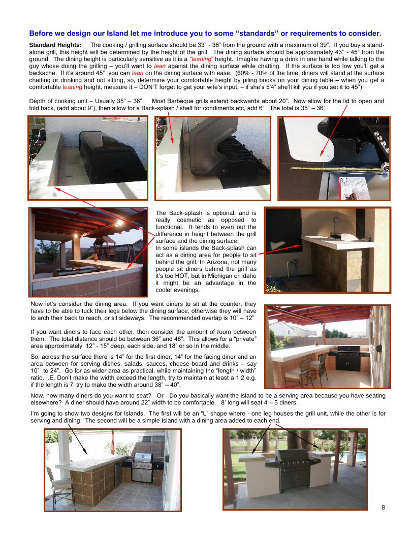
Before we design our Island let me introduce you to some “standards” or requirements to consider.
Standard Heights: The cooking / grilling surface should be 33” - 36” from the ground with a maximum of 39”. If you buy a stand-
alone grill, this height will be determined by the height of the grill. The dining surface should be approximately 43” - 45” from the ground. The dining height is particularly sensitive as it is a “leaning” height. Imagine having a drink in one hand while talking to the guy whose doing the grilling – you’ll want to lean against the dining surface while chatting. If the surface is too low you’ll get a backache. If it’s around 45” you can lean on the dining surface with ease. (60% - 70% of the time, diners will stand at the surface
chatting or drinking and not sitting, so, determine your comfortable height by piling books on your dining table – when you get a comfortable leaning height, measure it – DON’T forget to get your wife’s input. – if she’s 5’4” she’ll kill you if you set it to 45”) Depth of cooking unit – Usually 35” – 36” . Most Barbeque grills extend backwards about 20”. Now allow for the lid to open and fold back, (add about 9”), then allow for a Back-splash / shelf for condiments etc, add 6” The total is 35” – 36”
The Back-splash is optional, and is really cosmetic as opposed to functional. It tends to even out the difference in height between the grill surface and the dining surface. In some islands the Back-splash can act as a dining area for people to sit behind the grill. In Arizona, not many people sit diners behind the grill as it’s too HOT, but in Michigan or Idaho it might be an advantage in the cooler evenings.
Now let’s consider the dining area. If you want diners to sit at the counter, they have to be able to tuck their legs below the dining surface, otherwise they will have to arch their back to reach, or sit sideways. The recommended overlap is 10” – 12” If you want diners to face each other, then consider the amount of room between them. The total distance should be between 36” and 48”. This allows for a “private” area approximately 12” - 15” deep, each side, and 18” or so in the middle.
So, across the surface there is 14” for the first diner, 14” for the facing diner and an area between for serving dishes, salads, sauces, cheese-board and drinks – say 10” to 24”. Go for as wider area as practical, while maintaining the “length / width” ratio. I.E. Don’t make the width exceed the length, try to maintain at least a 1:2 e.g. if the length is 7’ try to make the width around 38” – 40”.
Now, how many diners do you want to seat? Or - Do you basically want the island to be a serving area because you have seating elsewhere? A diner should have around 22” width to be comfortable. 8’ long will seat 4 – 5 diners.
I’m going to show two designs for Islands. The first will be an “L” shape where - one leg houses the grill unit, while the other is for serving and dining. The second will be a simple Island with a dining area added to each end.
Side view of grill, lid open & splash-back
Dining behind grill and splash-back
Leg room for diners sitting opposite
9
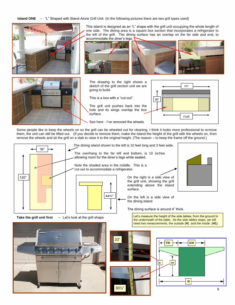
Island ONE -- “L” Shaped with Stand-Alone Grill Unit (In the following pictures there are two grill types used)
This island is designed as an “L” shape with the grill unit occupying the whole length of one side. The dining area is a square box section that incorporates a refrigerator to the left of the grill. The dining surface has an overlap on the far side and end, to accommodate the diner’s legs.
The drawing to the right shows a sketch of the grill section unit we are going to build. This is a box with a “cut-out”. The grill unit pushes back into the hole and its wings overlap the box surface. See here - I’ve removed the wheels.
Some people like to keep the wheels on so the grill can be wheeled out for cleaning. I think it looks more professional to remove them, the unit can still be lifted out. (If you decide to remove them, make the island the height of the grill with the wheels on, then remove the wheels and sit the grill on a slab to raise it to the original height. (The reason – to keep the frame off the ground.)
The dining island shown to the left is 10 feet long and 3 feet wide. The overhang to the far left and bottom, is 10 inches allowing room for the diner’s legs while seated. Note the shaded area in the middle. This is a cut-out to accommodate a refrigerator.
On the right is a side view of the grill unit, showing the grill extending above the island surface. On the left is a side view of the dining island The dining surface is around 4” thick.
Take the grill unit first -- Let’s look at the grill shape
.
Emily Grill “Char-Broil”
Emily dining far side overlap
Emily end overlap
Wall-Mart grill – 6’ wide
70”
36”’
Grill
120”
36”
44¾”
33”
30½”
Let’s measure the height of the side tables, from the ground to the underneath of the table. As the side tables slope, we will need two measurements, the outside (H) and the inside. (H1).
10
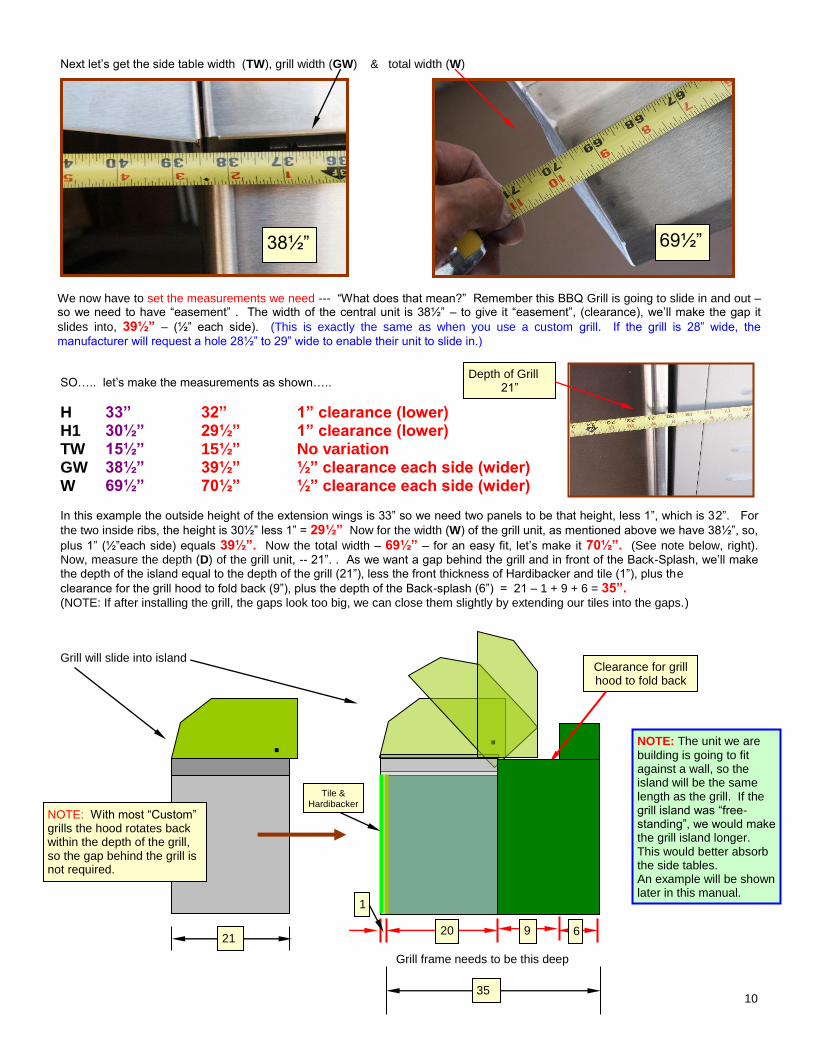
Next let’s get the side table width (TW), grill width (GW) & total width (W)
We now have to set the measurements we need --- “What does that mean?” Remember this BBQ Grill is going to slide in and out – so we need to have “easement” . The width of the central unit is 38½” – to give it “easement”, (clearance), we’ll make the gap it
slides into, 39½” – (½” each side). (This is exactly the same as when you use a custom grill. If the grill is 28” wide, the
manufacturer will request a hole 28½” to 29” wide to enable their unit to slide in.) SO….. let’s make the measurements as shown…..
H 33” 32” 1” clearance (lower) H1 30½” 29½” 1” clearance (lower) TW 15½” 15½” No variation GW 38½” 39½” ½” clearance each side (wider) W 69½” 70½” ½” clearance each side (wider) In this example the outside height of the extension wings is 33” so we need two panels to be that height, less 1”, which is 32”. For
the two inside ribs, the height is 30½” less 1” = 29½” Now for the width (W) of the grill unit, as mentioned above we have 38½”, so,
plus 1” (½”each side) equals 39½”. Now the total width – 69½” – for an easy fit, let’s make it 70½”. (See note below, right).
Now, measure the depth (D) of the grill unit, -- 21”. . As we want a gap behind the grill and in front of the Back-Splash, we’ll make
the depth of the island equal to the depth of the grill (21”), less the front thickness of Hardibacker and tile (1”), plus the
clearance for the grill hood to fold back (9”), plus the depth of the Back-splash (6”) = 21 – 1 + 9 + 6 = 35”. (NOTE: If after installing the grill, the gaps look too big, we can close them slightly by extending our tiles into the gaps.) Grill will slide into island
Grill frame needs to be this deep
38½”
Clearance for grill hood to fold back
Depth of Grill 21”
20 9 6
1
21
Tile & Hardibacker
.
NOTE: With most “Custom” grills the hood rotates back within the depth of the grill, so the gap behind the grill is not required.
. NOTE: The unit we are
building is going to fit against a wall, so the island will be the same length as the grill. If the grill island was “free-standing”, we would make the grill island longer. This would better absorb the side tables. An example will be shown later in this manual.
69½”
35
11
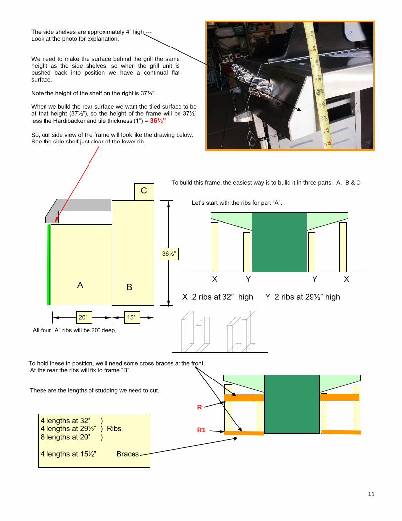
The side shelves are approximately 4” high --- Look at the photo for explanation. We need to make the surface behind the grill the same height as the side shelves, so when the grill unit is pushed back into position we have a continual flat surface. Note the height of the shelf on the right is 37½”. When we build the rear surface we want the tiled surface to be at that height (37½”), so the height of the frame will be 37½”
less the Hardibacker and tile thickness (1”) = 36½”
So, our side view of the frame will look like the drawing below. See the side shelf just clear of the lower rib
To build this frame, the easiest way is to build it in three parts. A, B & C
Let’s start with the ribs for part “A”.
X Y Y X
X 2 ribs at 32” high Y 2 ribs at 29½” high
All four “A” ribs will be 20” deep,
To hold these in position, we’ll need some cross braces at the front. At the rear the ribs will fix to frame “B”. These are the lengths of studding we need to cut.
4 lengths at 32” ) 4 lengths at 29½” ) Ribs 8 lengths at 20” ) 4 lengths at 15½” Braces
A B
C
36½”
20” 15”
R
R1
12
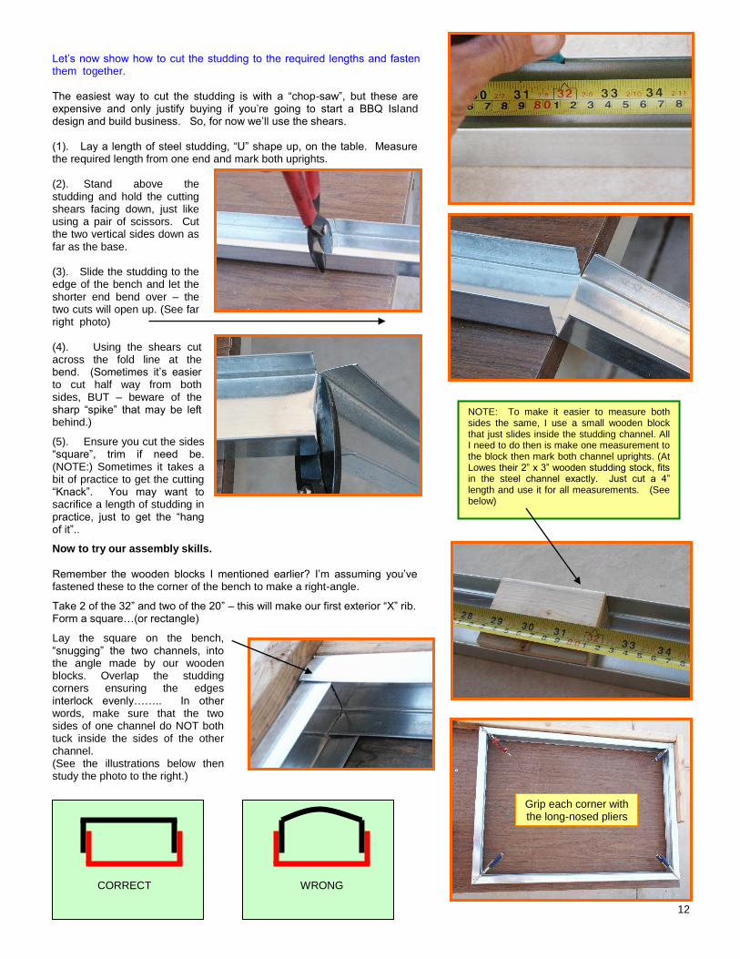
Let’s now show how to cut the studding to the required lengths and fasten them together. The easiest way to cut the studding is with a “chop-saw”, but these are expensive and only justify buying if you’re going to start a BBQ Island design and build business. So, for now we’ll use the shears. (1). Lay a length of steel studding, “U” shape up, on the table. Measure the required length from one end and mark both uprights. (2). Stand above the studding and hold the cutting shears facing down, just like using a pair of scissors. Cut the two vertical sides down as far as the base. (3). Slide the studding to the edge of the bench and let the shorter end bend over – the two cuts will open up. (See far right photo) (4). Using the shears cut across the fold line at the bend. (Sometimes it’s easier to cut half way from both sides, BUT – beware of the sharp “spike” that may be left behind.)
(5). Ensure you cut the sides “square”, trim if need be. (NOTE:) Sometimes it takes a bit of practice to get the cutting “Knack”. You may want to sacrifice a length of studding in practice, just to get the “hang of it”..
Now to try our assembly skills.
Remember the wooden blocks I mentioned earlier? I’m assuming you’ve fastened these to the corner of the bench to make a right-angle.
Take 2 of the 32” and two of the 20” – this will make our first exterior “X” rib. Form a square…(or rectangle)
Lay the square on the bench, “snugging” the two channels, into the angle made by our wooden blocks. Overlap the studding corners ensuring the edges interlock evenly…….. In other words, make sure that the two sides of one channel do NOT both tuck inside the sides of the other channel. (See the illustrations below then study the photo to the right.)
Shears cutting both sides.
Cutting across the studding bend with shears.
NOTE: To make it easier to measure both sides the same, I use a small wooden block that just slides inside the studding channel. All I need to do then is make one measurement to the block then mark both channel uprights. (At Lowes their 2” x 3” wooden studding stock, fits in the steel channel exactly. Just cut a 4” length and use it for all measurements. (See below)
CORRECT WRONG
Grip each corner with the long-nosed pliers
13
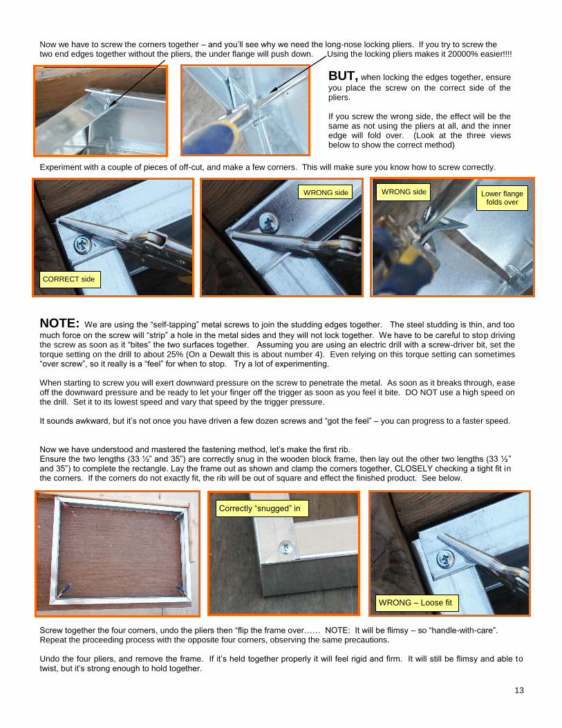
Now we have to screw the corners together – and you’ll see why we need the long-nose locking pliers. If you try to screw the two end edges together without the pliers, the under flange will push down. Using the locking pliers makes it 20000% easier!!!!
BUT, when locking the edges together, ensure
you place the screw on the correct side of the pliers. If you screw the wrong side, the effect will be the same as not using the pliers at all, and the inner edge will fold over. (Look at the three views below to show the correct method)
Experiment with a couple of pieces of off-cut, and make a few corners. This will make sure you know how to screw correctly.
NOTE: We are using the “self-tapping” metal screws to join the studding edges together. The steel studding is thin, and too
much force on the screw will “strip” a hole in the metal sides and they will not lock together. We have to be careful to stop driving the screw as soon as it “bites” the two surfaces together. Assuming you are using an electric drill with a screw-driver bit, set the torque setting on the drill to about 25% (On a Dewalt this is about number 4). Even relying on this torque setting can sometimes “over screw”, so it really is a “feel” for when to stop. Try a lot of experimenting. When starting to screw you will exert downward pressure on the screw to penetrate the metal. As soon as it breaks through, ease off the downward pressure and be ready to let your finger off the trigger as soon as you feel it bite. DO NOT use a high speed on the drill. Set it to its lowest speed and vary that speed by the trigger pressure. It sounds awkward, but it’s not once you have driven a few dozen screws and “got the feel” – you can progress to a faster speed. Now we have understood and mastered the fastening method, let’s make the first rib. Ensure the two lengths (33 ½” and 35”) are correctly snug in the wooden block frame, then lay out the other two lengths (33 ½” and 35”) to complete the rectangle. Lay the frame out as shown and clamp the corners together, CLOSELY checking a tight fit in the corners. If the corners do not exactly fit, the rib will be out of square and effect the finished product. See below.
Screw together the four corners, undo the pliers then “flip the frame over…… NOTE: It will be flimsy – so “handle-with-care”. Repeat the proceeding process with the opposite four corners, observing the same precautions. Undo the four pliers, and remove the frame. If it’s held together properly it will feel rigid and firm. It will still be flimsy and able to twist, but it’s strong enough to hold together.
Edges screwed without locking pliers
Edges screwed correctly using the locking pliers.
Correct side of pliers 1 Correct side of pliers 2
Correct side of pliers 3
Four side of rib squarely laid out and clamped
Clamped correctly – no gaps Bad fitting X
CORRECT side
WRONG side
WRONG side Lower flange
folds over
WRONG side
Correctly “snugged” in
WRONG – Loose fit
14
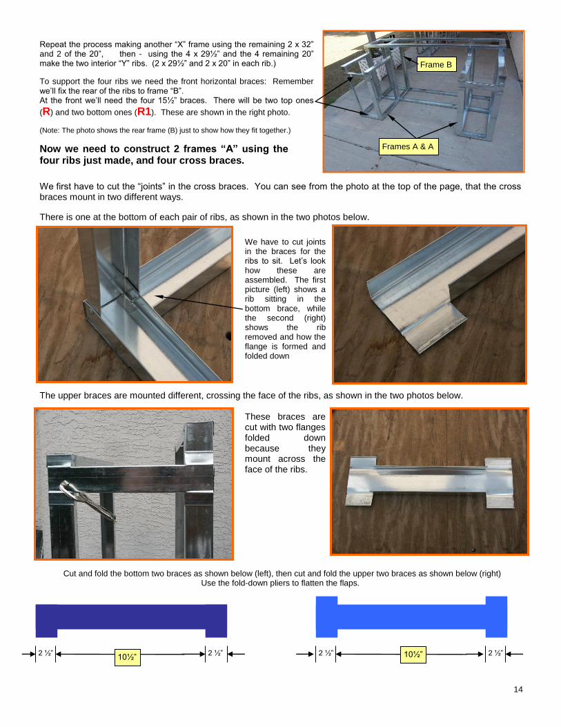
Repeat the process making another “X” frame using the remaining 2 x 32” and 2 of the 20”, then - using the 4 x 29½” and the 4 remaining 20” make the two interior “Y” ribs. (2 x 29½” and 2 x 20” in each rib.)
To support the four ribs we need the front horizontal braces: Remember we’ll fix the rear of the ribs to frame “B”. At the front we’ll need the four 15½” braces. There will be two top ones
(R) and two bottom ones (R1). These are shown in the right photo. (Note: The photo shows the rear frame (B) just to show how they fit together.)
Now we need to construct 2 frames “A” using the four ribs just made, and four cross braces.
We first have to cut the “joints” in the cross braces. You can see from the photo at the top of the page, that the cross braces mount in two different ways.
There is one at the bottom of each pair of ribs, as shown in the two photos below.
We have to cut joints in the braces for the ribs to sit. Let’s look how these are assembled. The first picture (left) shows a rib sitting in the bottom brace, while the second (right) shows the rib removed and how the flange is formed and folded down
The upper braces are mounted different, crossing the face of the ribs, as shown in the two photos below.
These braces are cut with two flanges folded down because they mount across the face of the ribs.
Cut and fold the bottom two braces as shown below (left), then cut and fold the upper two braces as shown below (right)
Use the fold-down pliers to flatten the flaps.
Back bottom rail in position
2 ½” 2 ½” 2 ½” 2 ½” 10½” 10½”
Frames A & A
Frame B
15
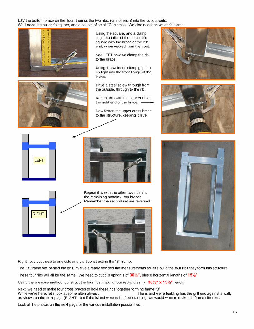
Lay the bottom brace on the floor, then sit the two ribs, (one of each) into the cut out-outs.
We’ll need the builder’s square, and a couple of small “C” clamps. We also need the welder’s clamp Using the square, and a clamp align the taller of the ribs so it’s square with the brace at the left end, when viewed from the front. See LEFT how we clamp the rib to the brace. Using the welder’s clamp grip the rib tight into the front flange of the brace. Drive a steel screw through from the outside, through to the rib. Repeat this with the shorter rib at the right end of the brace. Now fasten the upper cross brace to the structure, keeping it level.
Repeat this with the other two ribs and the remaining bottom & top braces. Remember the second set are reversed.
Right, let’s put these to one side and start constructing the “B” frame.
The “B” frame sits behind the grill. We’ve already decided the measurements so let’s build the four ribs thay form this structure.
These four ribs will all be the same. We need to cut : 8 uprights of 36½”, plus 8 horizontal lengths of 15½”
Using the previous method, construct the four ribs, making four rectangles - 36½” x 15½” each.
Next, we need to make four cross braces to hold these ribs together forming frame “B” While we’re here, let’s look at some alternatives : The island we’re building has the grill end against a wall, as shown on the next page (RIGHT), but if the island were to be free-standing, we would want to make the frame different.
Look at the photos on the next page or the various installation possibilities…
Rib in brace with builder’s square Welders clamp holding rib against brace
Screw left rib Screw right rib
Second set reversed
Show upper cross brace in position held with welder’s clamp
LEFT
RIGHT
16
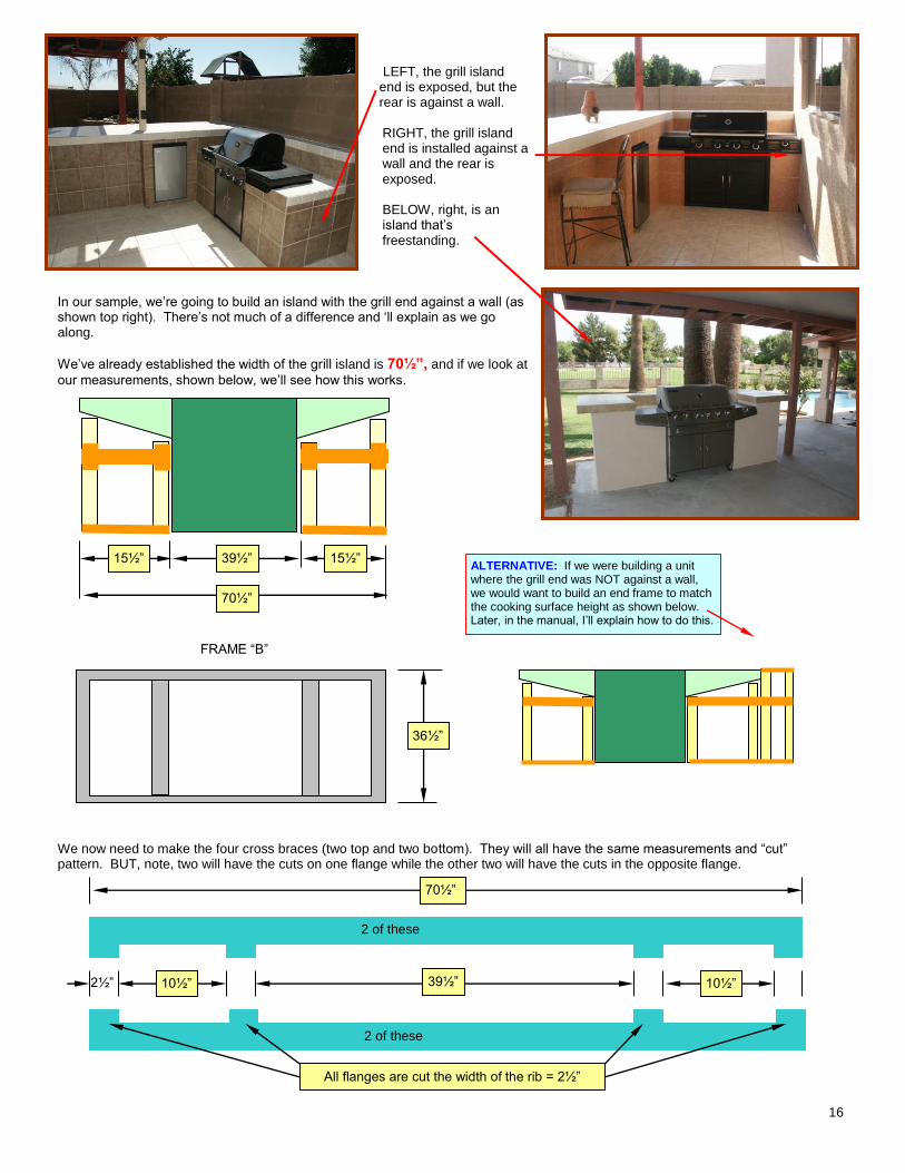
LEFT, the grill island end is exposed, but the rear is against a wall. RIGHT, the grill island end is installed against a wall and the rear is exposed. BELOW, right, is an island that’s freestanding.
In our sample, we’re going to build an island with the grill end against a wall (as shown top right). There’s not much of a difference and ‘ll explain as we go along.
We’ve already established the width of the grill island is 70½”, and if we look at
our measurements, shown below, we’ll see how this works.
FRAME “B”
We now need to make the four cross braces (two top and two bottom). They will all have the same measurements and “cut” pattern. BUT, note, two will have the cuts on one flange while the other two will have the cuts in the opposite flange.
39½” 15½” 15½”
70½”
36½”
ALTERNATIVE: If we were building a unit where the grill end was NOT against a wall, we would want to build an end frame to match the cooking surface height as shown below. Later, in the manual, I’ll explain how to do this.
70½”
39½” 10½” 10½” 2½”
All flanges are cut the width of the rib = 2½”
2 of these
2 of these
17
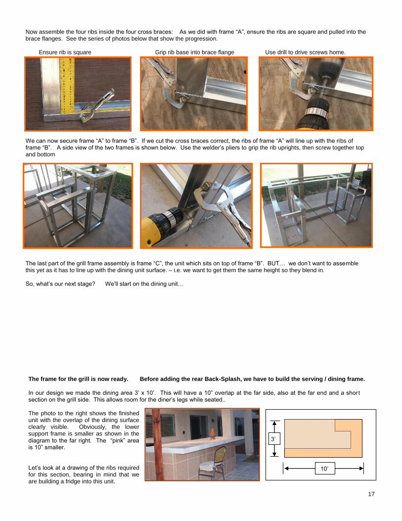
Now assemble the four ribs inside the four cross braces: As we did with frame “A”, ensure the ribs are square and pulled into the brace flanges. See the series of photos below that show the progression. Ensure rib is square Grip rib base into brace flange Use drill to drive screws home. We can now secure frame “A” to frame “B”. If we cut the cross braces correct, the ribs of frame “A” will line up with the ribs of frame “B”. A side view of the two frames is shown below. Use the welder’s pliers to grip the rib uprights, then screw together top and bottom The last part of the grill frame assembly is frame “C”, the unit which sits on top of frame “B”. BUT… we don’t want to assemble this yet as it has to line up with the dining unit surface. – i.e. we want to get them the same height so they blend in. So, what’s our next stage? We’ll start on the dining unit… The frame for the grill is now ready. Before adding the rear Back-Splash, we have to build the serving / dining frame.
In our design we made the dining area 3’ x 10’. This will have a 10” overlap at the far side, also at the far end and a shor t section on the grill side. This allows room for the diner’s legs while seated.. The photo to the right shows the finished unit with the overlap of the dining surface clearly visible. Obviously, the lower support frame is smaller as shown in the diagram to the far right. The “pink” area is 10” smaller. Let’s look at a drawing of the ribs required for this section, bearing in mind that we are building a fridge into this unit.
Dining with overlaps shown (Emily)
10’
3’
Builder’s square with rib in brace. Welder’s pliers gripping rib to flange Drill driving screw home.
Side view of frames joined. Screw together top and bottom.
Completed frame A & B joined
18
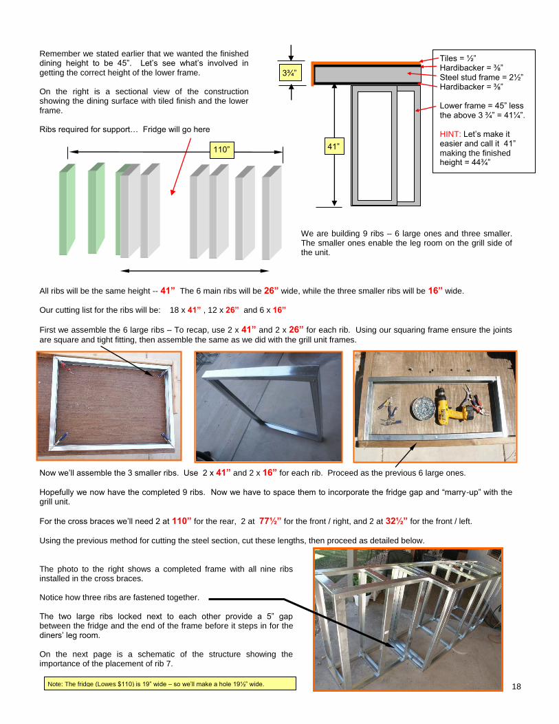
Remember we stated earlier that we wanted the finished dining height to be 45”. Let’s see what’s involved in getting the correct height of the lower frame. On the right is a sectional view of the construction showing the dining surface with tiled finish and the lower frame. Ribs required for support… Fridge will go here
We are building 9 ribs – 6 large ones and three smaller. The smaller ones enable the leg room on the grill side of the unit.
All ribs will be the same height -- 41” The 6 main ribs will be 26” wide, while the three smaller ribs will be 16” wide.
Our cutting list for the ribs will be: 18 x 41” , 12 x 26” and 6 x 16”
First we assemble the 6 large ribs – To recap, use 2 x 41” and 2 x 26” for each rib. Using our squaring frame ensure the joints
are square and tight fitting, then assemble the same as we did with the grill unit frames.
Now we’ll assemble the 3 smaller ribs. Use 2 x 41” and 2 x 16” for each rib. Proceed as the previous 6 large ones.
Hopefully we now have the completed 9 ribs. Now we have to space them to incorporate the fridge gap and “marry-up” with the grill unit.
For the cross braces we’ll need 2 at 110” for the rear, 2 at 77½” for the front / right, and 2 at 32½” for the front / left.
Using the previous method for cutting the steel section, cut these lengths, then proceed as detailed below. The photo to the right shows a completed frame with all nine ribs installed in the cross braces. Notice how three ribs are fastened together. The two large ribs locked next to each other provide a 5” gap between the fridge and the end of the frame before it steps in for the diners’ leg room. On the next page is a schematic of the structure showing the importance of the placement of rib 7.
Tiles = ½” Hardibacker = ⅜” Steel stud frame = 2½” Hardibacker = ⅜” Lower frame = 45” less the above 3 ¾” = 41¼”. HINT: Let’s make it easier and call it 41” making the finished height = 44¾”
3¾”
41” 110”
Dining frame showing all ribs and the three locked together.
Note: The fridge (Lowes $110) is 19” wide – so we’ll make a hole 19½” wide.
19
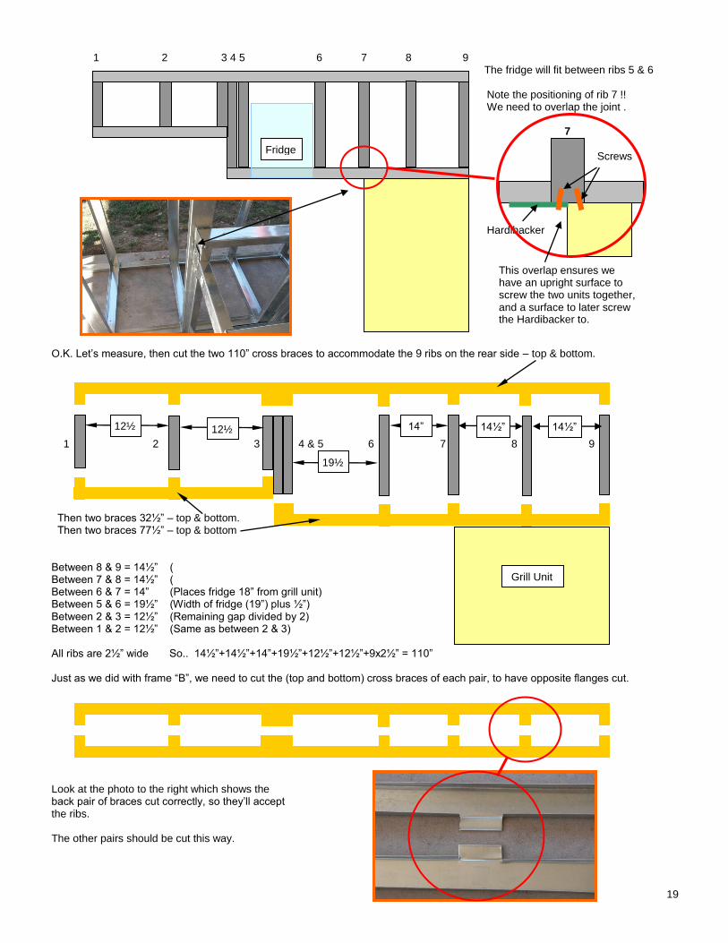
1 2 3 4 5 6 7 8 9 The fridge will fit between ribs 5 & 6 Note the positioning of rib 7 !! We need to overlap the joint . 7
Screws Hardibacker
O.K. Let’s measure, then cut the two 110” cross braces to accommodate the 9 ribs on the rear side – top & bottom.
1 2 3 4 & 5 6 7 8 9 Then two braces 32½” – top & bottom. Then two braces 77½” – top & bottom Between 8 & 9 = 14½” ( Between 7 & 8 = 14½” ( Between 6 & 7 = 14” (Places fridge 18” from grill unit) Between 5 & 6 = 19½” (Width of fridge (19”) plus ½”) Between 2 & 3 = 12½” (Remaining gap divided by 2) Between 1 & 2 = 12½” (Same as between 2 & 3) All ribs are 2½” wide So.. 14½”+14½”+14”+19½”+12½”+12½”+9x2½” = 110” Just as we did with frame “B”, we need to cut the (top and bottom) cross braces of each pair, to have opposite flanges cut. Look at the photo to the right which shows the back pair of braces cut correctly, so they’ll accept the ribs. The other pairs should be cut this way.
Fridge
This overlap ensures we have an upright surface to screw the two units together, and a surface to later screw the Hardibacker to.
Show frame overlap corner
Grill Unit
12½”
14½” 1/2
19½”
14” 12½”
14½” 1/2
20
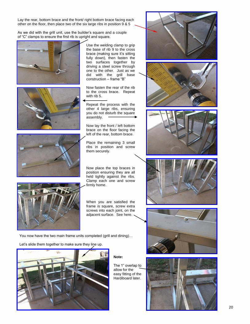
Lay the rear, bottom brace and the front/ right bottom brace facing each other on the floor, then place two of the six large ribs in position 9 & 5 As we did with the grill unit, use the builder’s square and a couple of “C” clamps to ensure the first rib is upright and square.
Use the welding clamp to grip the base of rib 9 to the cross brace (making sure it’s sitting fully down), then fasten the two surfaces together by driving a steel screw through one to the other. Just as we did with the grill base construction – frame “B” Now fasten the rear of the rib to the cross brace. Repeat with rib 5. Repeat the process with the other 4 large ribs, ensuring you do not disturb the square assembly. Now lay the front / left bottom brace on the floor facing the left of the rear, bottom brace. Place the remaining 3 small ribs in position and screw them securely. Now place the top braces in position ensuring they are all held tightly against the ribs. Clamp each one and screw firmly home. When you are satisfied the frame is square, screw extra screws into each joint, on the adjacent surface. See here.
You now have the two main frame units completed (grill and dining)… Let’s slide them together to make sure they line up.
Note:
The 1” overlap to allow for the easy fitting of the Hardiboard later.
Builder’s square holding rib 9 upright.
Drive steel screw through rib to base
Fasten front of rib to base
All five large ribs in position
Left front brace on floor
Top braces in position
21
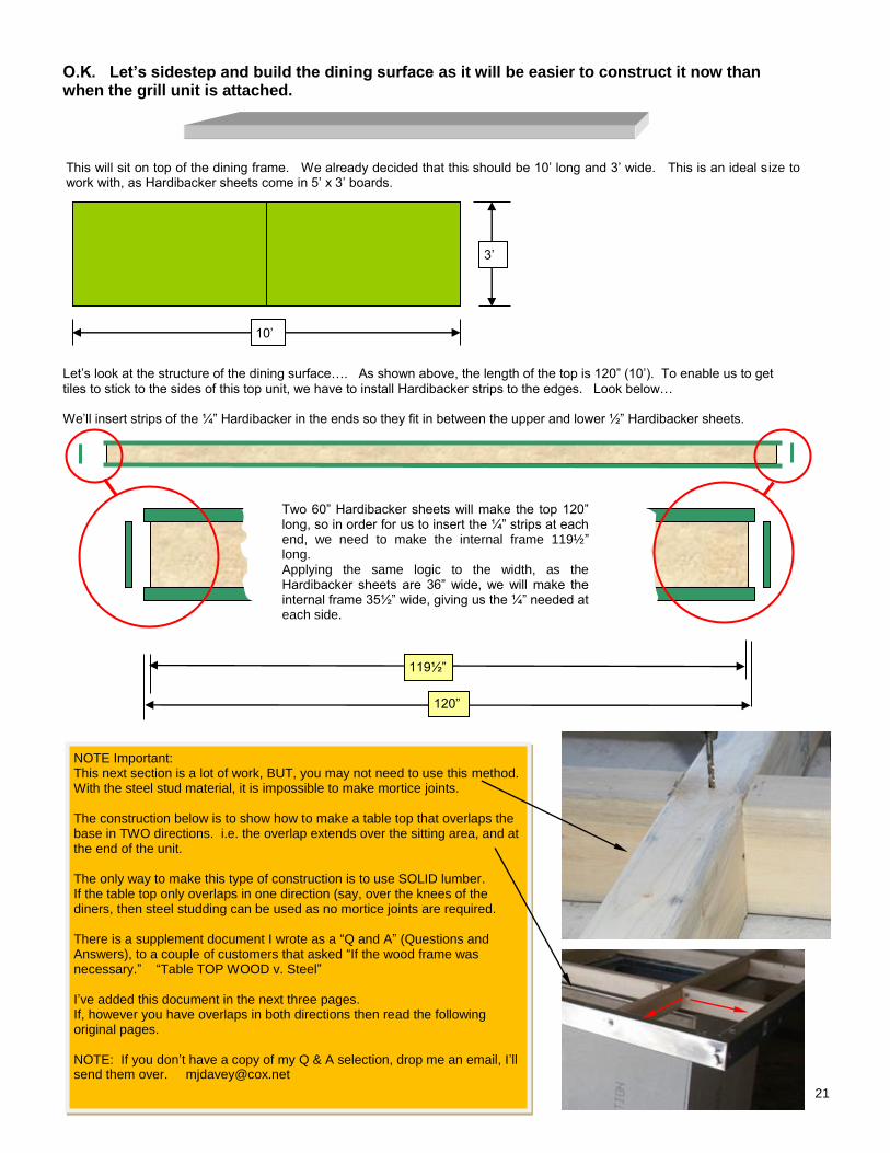
O.K. Let’s sidestep and build the dining surface as it will be easier to construct it now than when the grill unit is attached.
This will sit on top of the dining frame. We already decided that this should be 10’ long and 3’ wide. This is an ideal s ize to work with, as Hardibacker sheets come in 5’ x 3’ boards.
Let’s look at the structure of the dining surface…. As shown above, the length of the top is 120” (10’). To enable us to get tiles to stick to the sides of this top unit, we have to install Hardibacker strips to the edges. Look below… We’ll insert strips of the ¼” Hardibacker in the ends so they fit in between the upper and lower ½” Hardibacker sheets.
Two 60” Hardibacker sheets will make the top 120” long, so in order for us to insert the ¼” strips at each end, we need to make the internal frame 119½” long. Applying the same logic to the width, as the Hardibacker sheets are 36” wide, we will make the internal frame 35½” wide, giving us the ¼” needed at each side.
10’
3’
119½”
120”
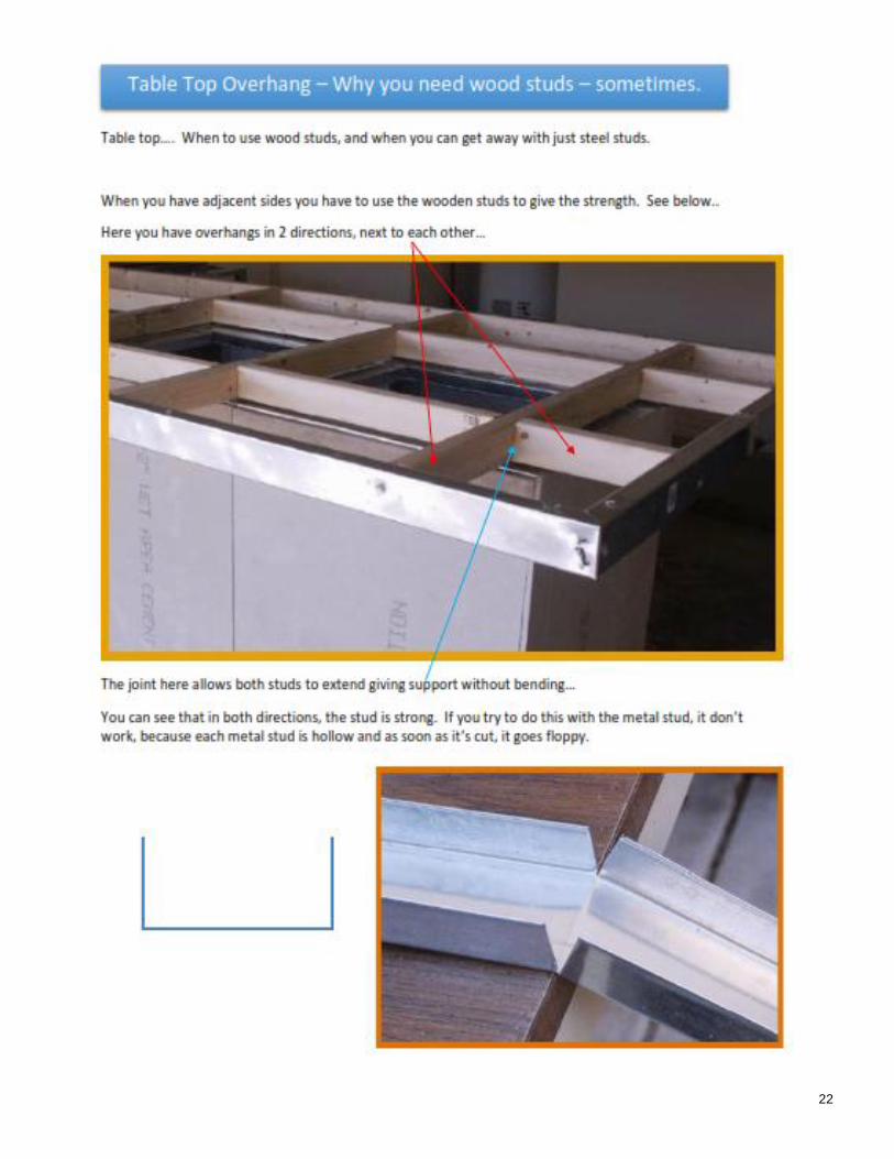
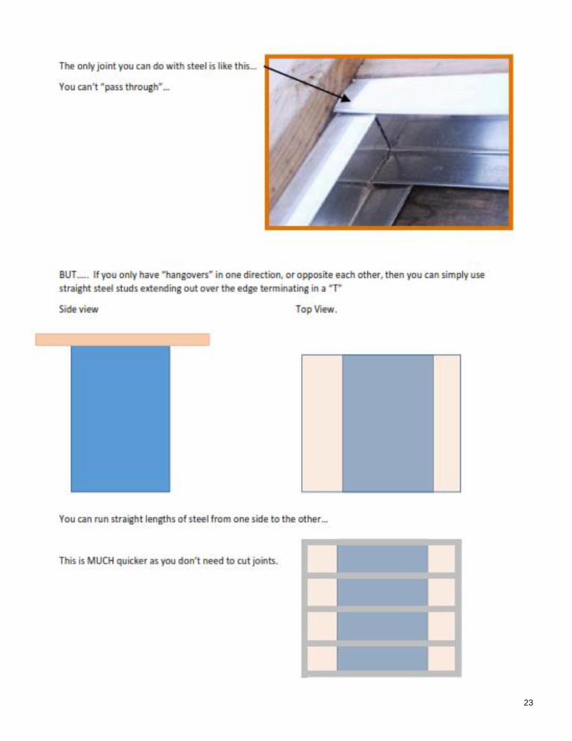
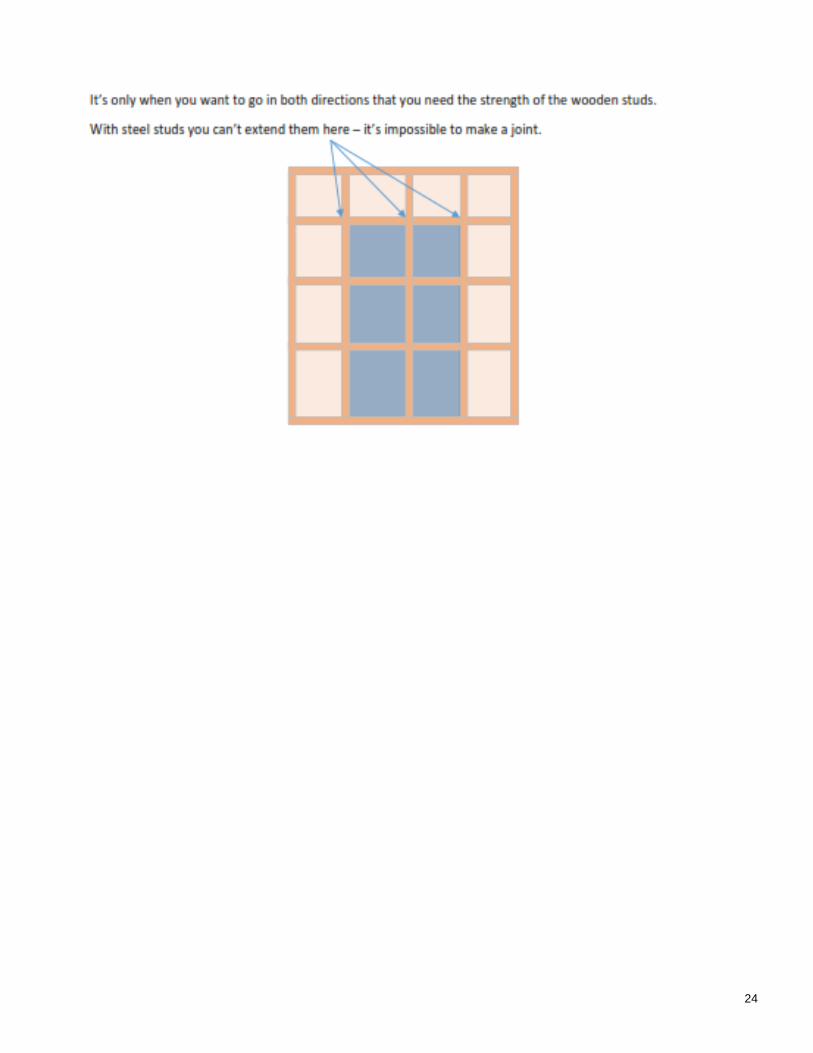
NOTE Important: This next section is a lot of work, BUT, you may not need to use this method. With the steel stud material, it is impossible to make mortice joints. The construction below is to show how to make a table top that overlaps the base in TWO directions. i.e. the overlap extends over the sitting area, and at the end of the unit. The only way to make this type of construction is to use SOLID lumber. If the table top only overlaps in one direction (say, over the knees of the diners, then steel studding can be used as no mortice joints are required. There is a supplement document I wrote as a “Q and A” (Questions and Answers), to a couple of customers that asked “If the wood frame was necessary.” “Table TOP WOOD v. Steel” I’ve added this document in the next three pages. If, however you have overlaps in both directions then read the following original pages. NOTE: If you don’t have a copy of my Q & A selection, drop me an email, I’ll send them over. [email protected]
22
23
24
25
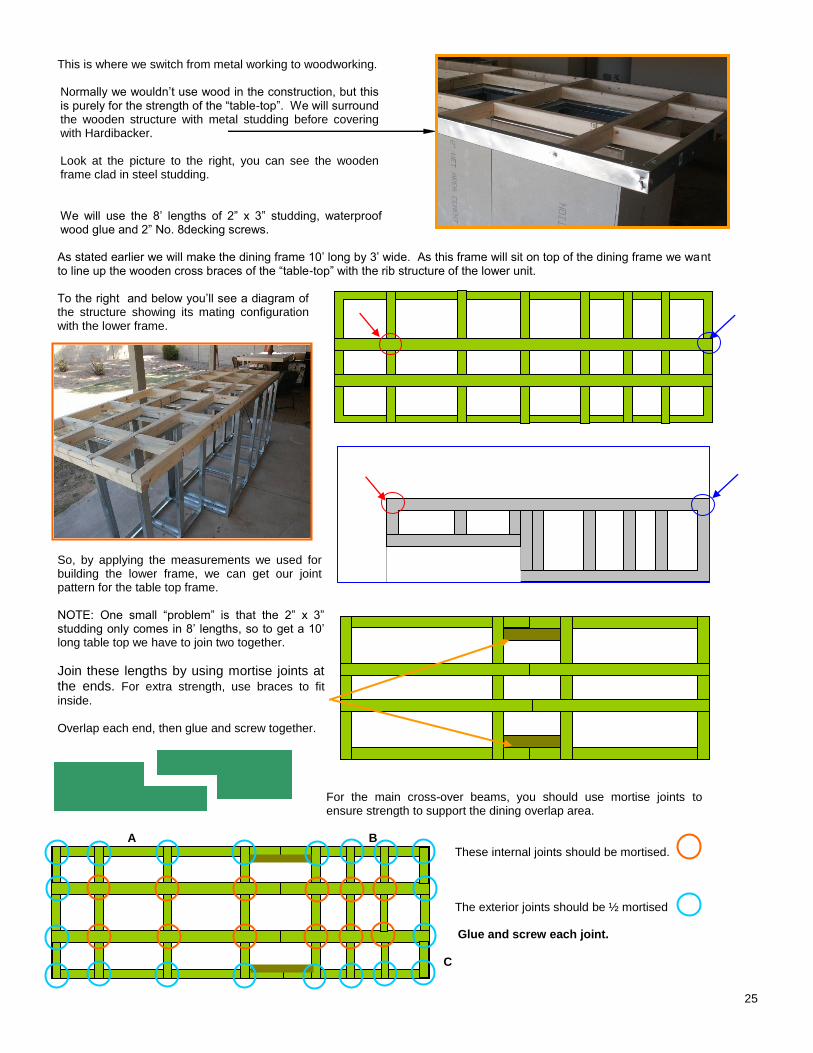
This is where we switch from metal working to woodworking. Normally we wouldn’t use wood in the construction, but this is purely for the strength of the “table-top”. We will surround the wooden structure with metal studding before covering with Hardibacker. Look at the picture to the right, you can see the wooden frame clad in steel studding. We will use the 8’ lengths of 2” x 3” studding, waterproof wood glue and 2” No. 8decking screws. As stated earlier we will make the dining frame 10’ long by 3’ wide. As this frame will sit on top of the dining frame we want to line up the wooden cross braces of the “table-top” with the rib structure of the lower unit. To the right and below you’ll see a diagram of the structure showing its mating configuration with the lower frame. So, by applying the measurements we used for building the lower frame, we can get our joint pattern for the table top frame. NOTE: One small “problem” is that the 2” x 3” studding only comes in 8’ lengths, so to get a 10’ long table top we have to join two together.
Join these lengths by using mortise joints at the ends. For extra strength, use braces to fit
inside. Overlap each end, then glue and screw together.
For the main cross-over beams, you should use mortise joints to ensure strength to support the dining overlap area.
A B
These internal joints should be mortised.
The exterior joints should be ½ mortised
Glue and screw each joint.
C
Table top wood with steel cladding.
Table top on top of frame
26
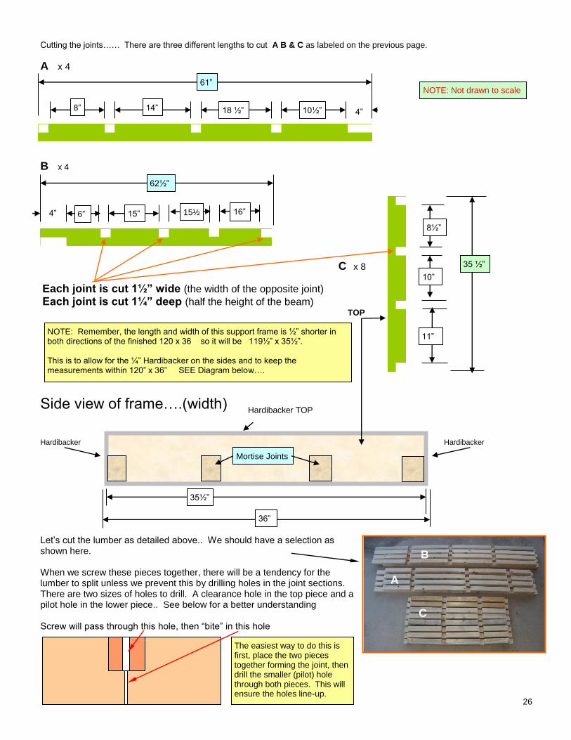
Cutting the joints…… There are three different lengths to cut A B & C as labeled on the previous page.
A x 4
B x 4
C x 8
Each joint is cut 1½” wide (the width of the opposite joint) Each joint is cut 1¼” deep (half the height of the beam)
TOP
Side view of frame….(width)
Hardibacker Hardibacker
Let’s cut the lumber as detailed above.. We should have a selection as shown here. When we screw these pieces together, there will be a tendency for the lumber to split unless we prevent this by drilling holes in the joint sections. There are two sizes of holes to drill. A clearance hole in the top piece and a pilot hole in the lower piece.. See below for a better understanding Screw will pass through this hole, then “bite” in this hole
15½”
15”
18 ½” 1/2”
4”
4”
10½” ”
6”
14” 1/2”
8”
8½”
10”
11”
35 ½”
NOTE: Remember, the length and width of this support frame is ½” shorter in both directions of the finished 120 x 36 so it will be 119½” x 35½”. This is to allow for the ¼” Hardibacker on the sides and to keep the measurements within 120” x 36” SEE Diagram below….
35½”
36”
Hardibacker TOP
Mortise Joints
61”
62½”
16”
NOTE: Not drawn to scale
The easiest way to do this is first, place the two pieces together forming the joint, then drill the smaller (pilot) hole through both pieces. This will ensure the holes line-up.
A
B
C
27
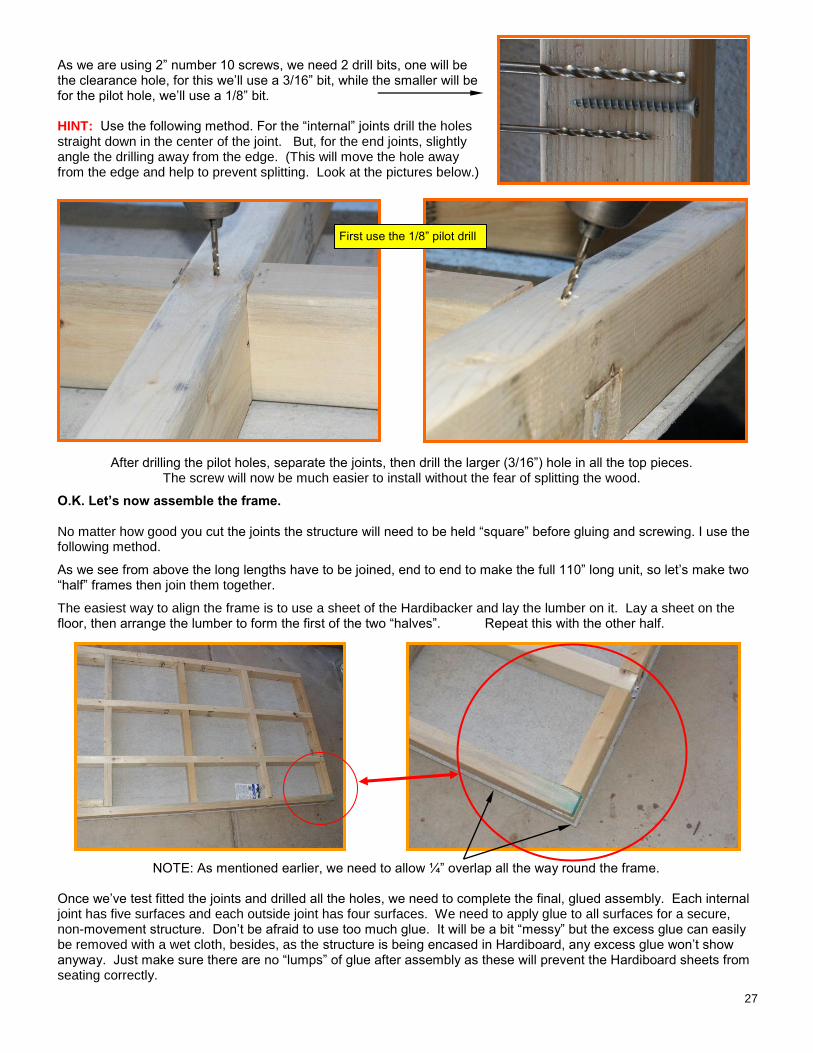
As we are using 2” number 10 screws, we need 2 drill bits, one will be the clearance hole, for this we’ll use a 3/16” bit, while the smaller will be for the pilot hole, we’ll use a 1/8” bit. HINT: Use the following method. For the “internal” joints drill the holes straight down in the center of the joint. But, for the end joints, slightly angle the drilling away from the edge. (This will move the hole away from the edge and help to prevent splitting. Look at the pictures below.)
After drilling the pilot holes, separate the joints, then drill the larger (3/16”) hole in all the top pieces. The screw will now be much easier to install without the fear of splitting the wood.
O.K. Let’s now assemble the frame. No matter how good you cut the joints the structure will need to be held “square” before gluing and screwing. I use the following method.
As we see from above the long lengths have to be joined, end to end to make the full 110” long unit, so let’s make two “half” frames then join them together.
The easiest way to align the frame is to use a sheet of the Hardibacker and lay the lumber on it. Lay a sheet on the floor, then arrange the lumber to form the first of the two “halves”. Repeat this with the other half.
NOTE: As mentioned earlier, we need to allow ¼” overlap all the way round the frame. Once we’ve test fitted the joints and drilled all the holes, we need to complete the final, glued assembly. Each internal joint has five surfaces and each outside joint has four surfaces. We need to apply glue to all surfaces for a secure, non-movement structure. Don’t be afraid to use too much glue. It will be a bit “messy” but the excess glue can easily be removed with a wet cloth, besides, as the structure is being encased in Hardiboard, any excess glue won’t show anyway. Just make sure there are no “lumps” of glue after assembly as these will prevent the Hardiboard sheets from seating correctly.
First use the 1/8” pilot drill
28
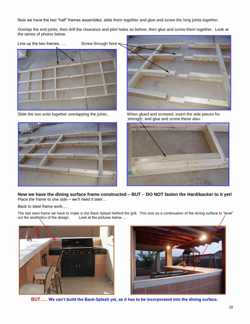
Now we have the two “half” frames assembled, slide them together and glue and screw the long joints together. Overlap the end joints, then drill the clearance and pilot holes as before, then glue and screw them together. Look at the series of photos below. Line up the two frames….. Screw through here Slide the two units together overlapping the joints.. When glued and screwed, insert the side pieces for
strength, and glue and screw these also.
Now we have the dining surface frame constructed – BUT - DO NOT fasten the Hardibacker to it yet! Place the frame to one side – we’ll need it later…
Back to steel frame work….
The last steel frame we have to make is the Back-Splash behind the grill. This acts as a continuation of the dining surface to “level” out the aesthetics of the design. Look at the pictures below….
BUT….. We can’t build the Back-Splash yet, as it has to be incorporated into the dining surface.
29
Let’s see where we are and assemble what we have…. But first….. A bit of study…
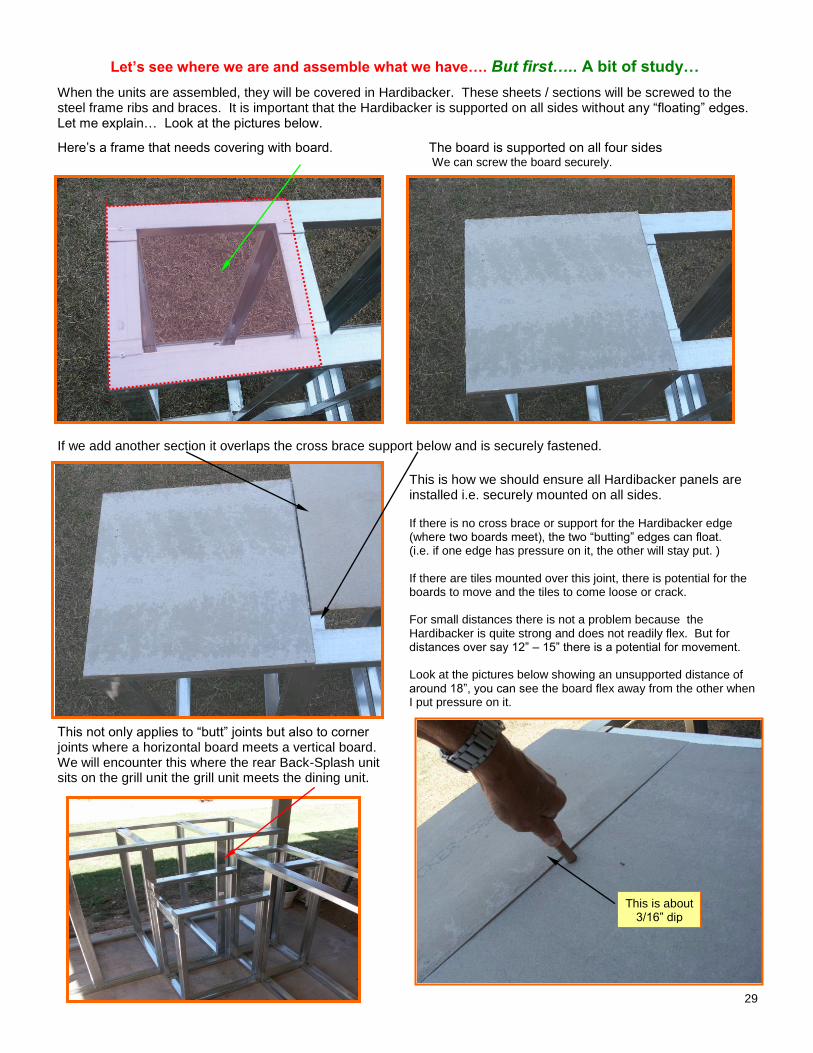
When the units are assembled, they will be covered in Hardibacker. These sheets / sections will be screwed to the steel frame ribs and braces. It is important that the Hardibacker is supported on all sides without any “floating” edges. Let me explain… Look at the pictures below.
Here’s a frame that needs covering with board. The board is supported on all four sides We can screw the board securely.
If we add another section it overlaps the cross brace support below and is securely fastened.
This is how we should ensure all Hardibacker panels are installed i.e. securely mounted on all sides. If there is no cross brace or support for the Hardibacker edge (where two boards meet), the two “butting” edges can float. (i.e. if one edge has pressure on it, the other will stay put. ) If there are tiles mounted over this joint, there is potential for the boards to move and the tiles to come loose or crack. For small distances there is not a problem because the Hardibacker is quite strong and does not readily flex. But for distances over say 12” – 15” there is a potential for movement. Look at the pictures below showing an unsupported distance of around 18”, you can see the board flex away from the other when I put pressure on it.
This not only applies to “butt” joints but also to corner joints where a horizontal board meets a vertical board. We will encounter this where the rear Back-Splash unit sits on the grill unit the grill unit meets the dining unit.
This is about 3/16” dip

30
Let’s look at how we handle corner joints…. Here we are looking at the rear of the GRILL unit just behind the BBQ. Two Hardibacker sheets meet here. The left picture shows the frame, and the right shows the two sheets in position. Note: Although the vertical sheet has a lower, back support (i.e. screws can go through here), there is no bottom support for the horizontal sheet. If you press down here, the board will dip. When tiles are adhered to the surfaces and there is pressure on the joint, the seal (grouting) will crack and allow water penetration. The way to “fix” this, (give the horizontal sheet some support), is to fasten a extra brace along the joint line. There is a sample shown in the picture to the right. As we progress through the construction phase we will need to provide these types of support as we encounter them.
It’s very easy to cut and install these braces as required.
So much for the lesson, let’s get back to construction!!!
First thing we’ll do, is join together the dining unit and the grill unit. As mentioned above there will be a joint between the two units where vertical and horizontal Hardibacker sections meet.
This is shown in the photo on the previous page and enlarged here, on the right. There will be a joint here: BUT, Note what happens here though: The upright board will fix to the 2 vertical and one upper surfaces but there is no lower surface for it to fix to. This is where the left “wing” of the BBQ unit sits. i.e. the left, steel, shelf touches the vertical board. To give strength to both these vertical surfaces we need to install a cross brace as shown below. NOTE: Position this beam so it can accommodate both sections of Hardibacker. I.e. The left end will not touch the bottom but will give sufficient support..
Cut a cross brace as shown and install it here.
14½”
36½”
5½”
31
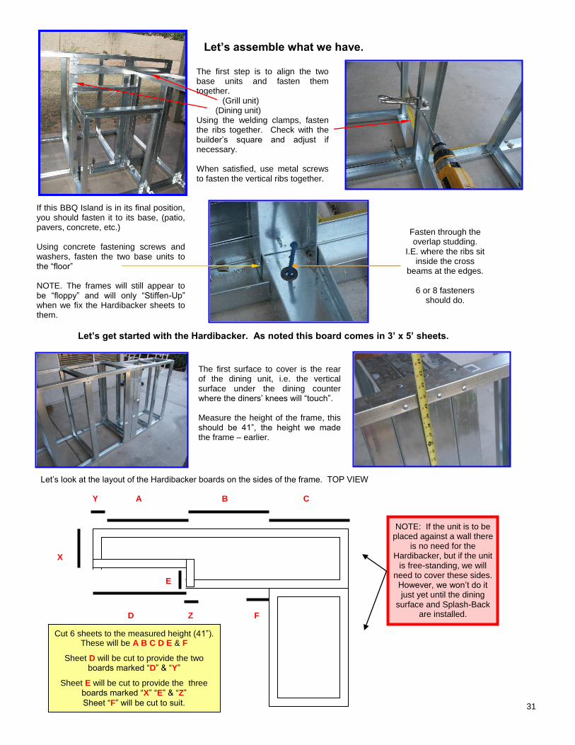
Let’s assemble what we have.
The first step is to align the two base units and fasten them together. (Grill unit) (Dining unit) Using the welding clamps, fasten the ribs together. Check with the builder’s square and adjust if necessary. When satisfied, use metal screws to fasten the vertical ribs together.
If this BBQ Island is in its final position, you should fasten it to its base, (patio, pavers, concrete, etc.) Using concrete fastening screws and washers, fasten the two base units to the “floor” NOTE. The frames will still appear to be “floppy” and will only “Stiffen-Up” when we fix the Hardibacker sheets to them.
Let’s get started with the Hardibacker. As noted this board comes in 3’ x 5’ sheets.
The first surface to cover is the rear of the dining unit, i.e. the vertical surface under the dining counter where the diners’ knees will “touch”. Measure the height of the frame, this should be 41”, the height we made the frame – earlier.
Let’s look at the layout of the Hardibacker boards on the sides of the frame. TOP VIEW Y A B C
X
D Z F
Fasten through the overlap studding.
I.E. where the ribs sit inside the cross
beams at the edges.
6 or 8 fasteners should do.
Frame showing vertical surface for Hardibacker
Measure height of unit for Hardibacker.
NOTE: If the unit is to be placed against a wall there
is no need for the Hardibacker, but if the unit
is free-standing, we will need to cover these sides.
However, we won’t do it just yet until the dining
surface and Splash-Back are installed.
Cut 6 sheets to the measured height (41”). These will be A B C D E & F
Sheet D will be cut to provide the two boards marked “D” & “Y”
Sheet E will be cut to provide the three boards marked “X” “E” & “Z”
Sheet “F” will be cut to suit.
E
32
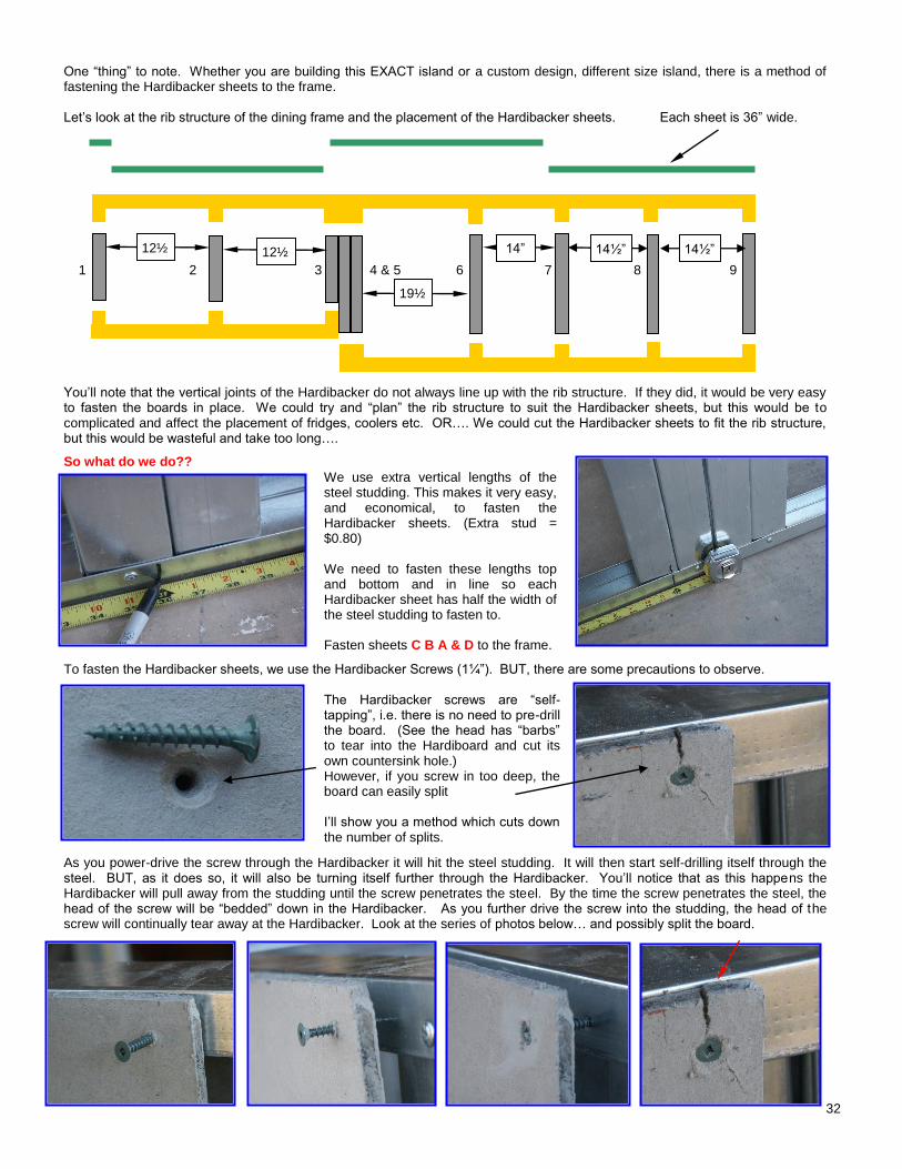
One “thing” to note. Whether you are building this EXACT island or a custom design, different size island, there is a method of fastening the Hardibacker sheets to the frame. Let’s look at the rib structure of the dining frame and the placement of the Hardibacker sheets. Each sheet is 36” wide. 1 2 3 4 & 5 6 7 8 9 You’ll note that the vertical joints of the Hardibacker do not always line up with the rib structure. If they did, it would be very easy to fasten the boards in place. We could try and “plan” the rib structure to suit the Hardibacker sheets, but this would be to complicated and affect the placement of fridges, coolers etc. OR…. We could cut the Hardibacker sheets to fit the rib structure, but this would be wasteful and take too long….
So what do we do??
We use extra vertical lengths of the steel studding. This makes it very easy, and economical, to fasten the Hardibacker sheets. (Extra stud = $0.80) We need to fasten these lengths top and bottom and in line so each Hardibacker sheet has half the width of the steel studding to fasten to. Fasten sheets C B A & D to the frame.
To fasten the Hardibacker sheets, we use the Hardibacker Screws (1¼”). BUT, there are some precautions to observe.
The Hardibacker screws are “self-tapping”, i.e. there is no need to pre-drill the board. (See the head has “barbs” to tear into the Hardiboard and cut its own countersink hole.) However, if you screw in too deep, the board can easily split I’ll show you a method which cuts down the number of splits.
As you power-drive the screw through the Hardibacker it will hit the steel studding. It will then start self-drilling itself through the steel. BUT, as it does so, it will also be turning itself further through the Hardibacker. You’ll notice that as this happens the Hardibacker will pull away from the studding until the screw penetrates the steel. By the time the screw penetrates the steel, the head of the screw will be “bedded” down in the Hardibacker. As you further drive the screw into the studding, the head of the screw will continually tear away at the Hardibacker. Look at the series of photos below… and possibly split the board.
Extra vertical lengths of studding showing half and half Hardibacker overlap
Split board.
12½”
14½” 1/2
19½”
14” 12½”
14½” 1/2
33
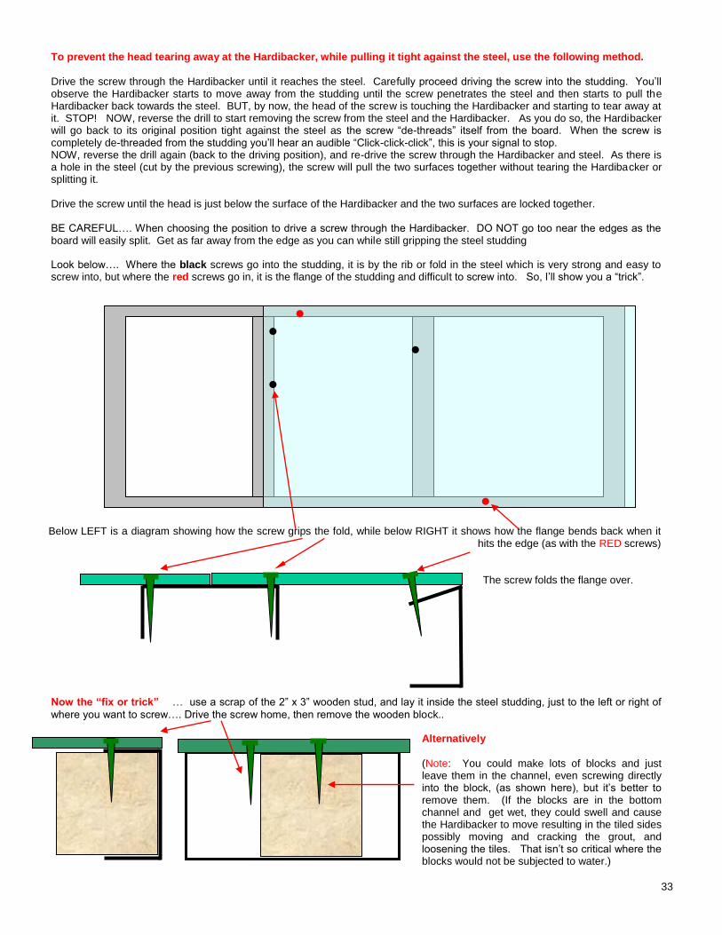
To prevent the head tearing away at the Hardibacker, while pulling it tight against the steel, use the following method.
Drive the screw through the Hardibacker until it reaches the steel. Carefully proceed driving the screw into the studding. You’ll observe the Hardibacker starts to move away from the studding until the screw penetrates the steel and then starts to pull the Hardibacker back towards the steel. BUT, by now, the head of the screw is touching the Hardibacker and starting to tear away at it. STOP! NOW, reverse the drill to start removing the screw from the steel and the Hardibacker. As you do so, the Hardibacker will go back to its original position tight against the steel as the screw “de-threads” itself from the board. When the screw is completely de-threaded from the studding you’ll hear an audible “Click-click-click”, this is your signal to stop. NOW, reverse the drill again (back to the driving position), and re-drive the screw through the Hardibacker and steel. As there is a hole in the steel (cut by the previous screwing), the screw will pull the two surfaces together without tearing the Hardibacker or splitting it. Drive the screw until the head is just below the surface of the Hardibacker and the two surfaces are locked together. BE CAREFUL…. When choosing the position to drive a screw through the Hardibacker. DO NOT go too near the edges as the board will easily split. Get as far away from the edge as you can while still gripping the steel studding Look below…. Where the black screws go into the studding, it is by the rib or fold in the steel which is very strong and easy to screw into, but where the red screws go in, it is the flange of the studding and difficult to screw into. So, I’ll show you a “trick”.
Below LEFT is a diagram showing how the screw grips the fold, while below RIGHT it shows how the flange bends back when it
hits the edge (as with the RED screws)
The screw folds the flange over. Now the “fix or trick” … use a scrap of the 2” x 3” wooden stud, and lay it inside the steel studding, just to the left or right of
where you want to screw…. Drive the screw home, then remove the wooden block..
Alternatively
(Note: You could make lots of blocks and just leave them in the channel, even screwing directly into the block, (as shown here), but it’s better to remove them. (If the blocks are in the bottom channel and get wet, they could swell and cause the Hardibacker to move resulting in the tiled sides possibly moving and cracking the grout, and loosening the tiles. That isn’t so critical where the blocks would not be subjected to water.)
●
●
●
●
●
34
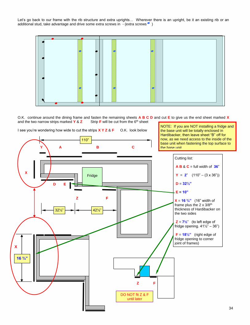
Let’s go back to our frame with the rib structure and extra uprights… Wherever there is an upright, be it an existing rib or an additional stud, take advantage and drive some extra screws in - (extra screws ) O.K. continue around the dining frame and fasten the remaining sheets A B C D and cut E to give us the end sheet marked X and the two narrow strips marked Y & Z Strip F will be cut from the 6th sheet
I see you’re wondering how wide to cut the strips X Y Z & F O.K. look below
Y A B C
X
Z F
Z F
Cutting list: A B & C = full width of 36”
Y = 2” (110” – (3 x 36”))
D = 32½” E = 10”
X = 16 ¾” (16” width of
frame plus the 2 x 3/8th thickness of Hardibacker on the two sides Z = 7½” (to left edge of
fridge opening. 41½” – 36”) F = 18½” (right edge of
fridge opening to corner joint of frames)
16 ¾”
NOTE: If you are NOT installing a fridge and the base unit will be totally enclosed in Hardibacker, then leave sheet “B” off for now, as we need access to the inside of the base unit when fastening the top surface to the base unit.
Fridge
D E
42½” 32½”
110”
X
DO NOT fit Z & F until later
35
Top View
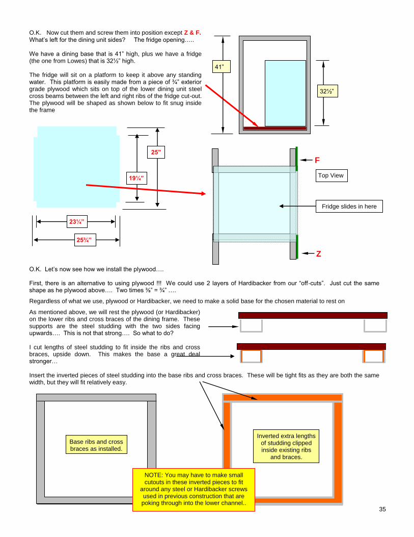
O.K. Now cut them and screw them into position except Z & F.
What’s left for the dining unit sides? The fridge opening….. We have a dining base that is 41” high, plus we have a fridge (the one from Lowes) that is 32½” high. The fridge will sit on a platform to keep it above any standing water. This platform is easily made from a piece of ¾” exterior grade plywood which sits on top of the lower dining unit steel cross beams between the left and right ribs of the fridge cut-out. The plywood will be shaped as shown below to fit snug inside the frame
F
Z O.K. Let’s now see how we install the plywood…. First, there is an alternative to using plywood !!! We could use 2 layers of Hardibacker from our “off-cuts”. Just cut the same shape as he plywood above…. Two times ⅜” = ¾” ….
Regardless of what we use, plywood or Hardibacker, we need to make a solid base for the chosen material to rest on
As mentioned above, we will rest the plywood (or Hardibacker) on the lower ribs and cross braces of the dining frame. These supports are the steel studding with the two sides facing upwards…. This is not that strong…. So what to do? I cut lengths of steel studding to fit inside the ribs and cross braces, upside down. This makes the base a great deal stronger… Insert the inverted pieces of steel studding into the base ribs and cross braces. These will be tight fits as they are both the same width, but they will fit relatively easy.
23¼”
25¾”
19¼”
25”
Base ribs and cross braces as installed.
Inverted extra lengths of studding clipped inside existing ribs
and braces.
41”
32½”
Fridge slides in here
NOTE: You may have to make small cutouts in these inverted pieces to fit
around any steel or Hardibacker screws used in previous construction that are
poking through into the lower channel..
36
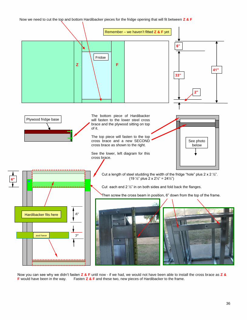
Now we need to cut the top and bottom Hardibacker pieces for the fridge opening that will fit between Z & F
The bottom piece of Hardibacker will fasten to the lower steel cross brace and the plywood sitting on top of it. The top piece will fasten to the top cross brace and a new SECOND cross brace as shown to the right. See the lower, left diagram for this cross brace.
Cut a length of steel studding the width of the fridge “hole” plus 2 x 2 ½”. (19 ½” plus 2 x 2½” = 24½”) Cut each end 2 ½” in on both sides and fold back the flanges. Then screw the cross beam in position, 6” down from the top of the frame.
Now you can see why we didn’t fasten Z & F until now - if we had, we would not have been able to install the cross brace as Z & F would have been in the way. Fasten Z & F and these two, new pieces of Hardibacker to the frame.
33”
41”
6”
2”
6”
2”
6”
Z F
Remember – we haven’t fitted Z & F yet
Hardibacker fits here
and here
Fridge
Plywood fridge base
See photo below
37
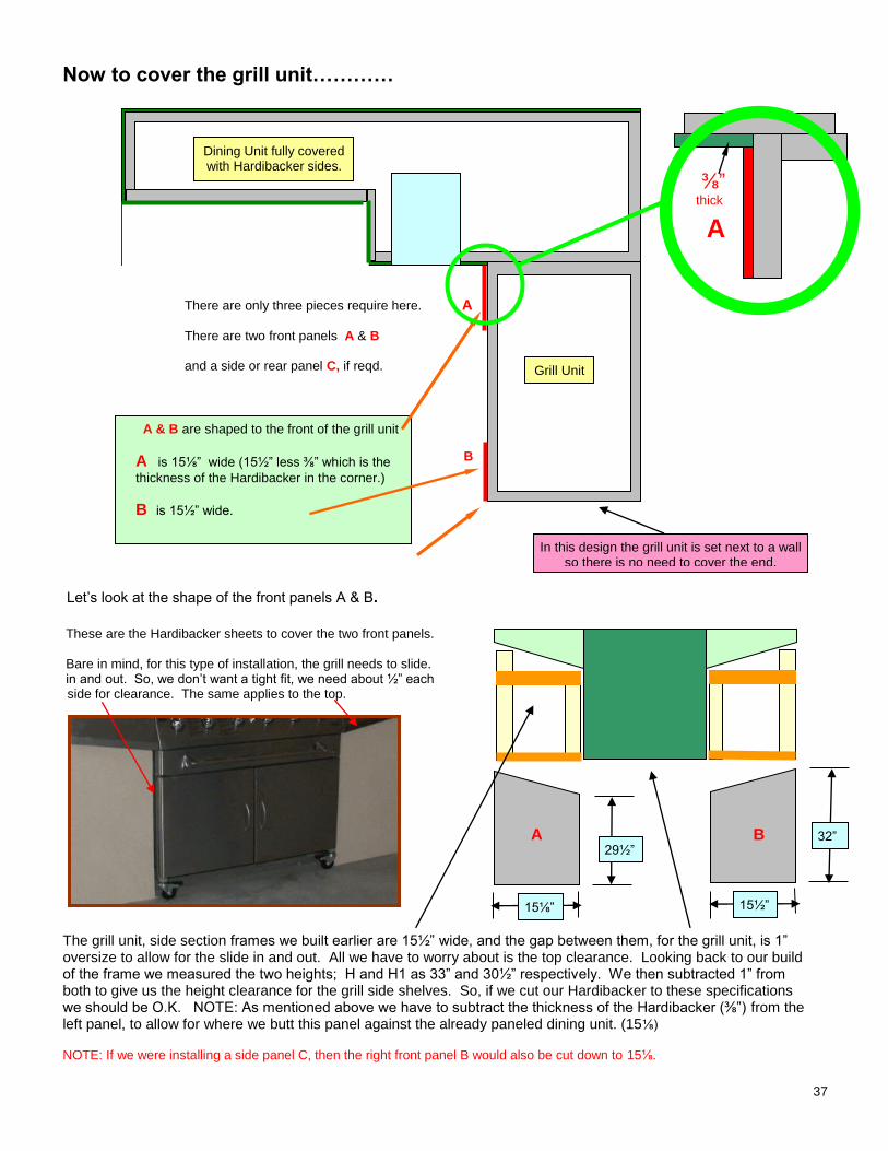
Now to cover the grill unit…………
There are only three pieces require here. A
There are two front panels A & B
and a side or rear panel C, if reqd.
B
\
Let’s look at the shape of the front panels A & B.
These are the Hardibacker sheets to cover the two front panels. Bare in mind, for this type of installation, the grill needs to slide. in and out. So, we don’t want a tight fit, we need about ½” each side for clearance. The same applies to the top.
The grill unit, side section frames we built earlier are 15½” wide, and the gap between them, for the grill unit, is 1” oversize to allow for the slide in and out. All we have to worry about is the top clearance. Looking back to our build of the frame we measured the two heights; H and H1 as 33” and 30½” respectively. We then subtracted 1” from both to give us the height clearance for the grill side shelves. So, if we cut our Hardibacker to these specifications we should be O.K. NOTE: As mentioned above we have to subtract the thickness of the Hardibacker (⅜”) from the left panel, to allow for where we butt this panel against the already paneled dining unit. (15⅛)
NOTE: If we were installing a side panel C, then the right front panel B would also be cut down to 15⅛.
Dining Unit fully covered with Hardibacker sides.
A & B are shaped to the front of the grill unit
A is 15⅛” wide (15½” less ⅜” which is the
thickness of the Hardibacker in the corner.)
B is 15½” wide.
A
⅜” thick
Grill Unit
A B 29½”
32”
15⅛” 15½””
In this design the grill unit is set next to a wall so there is no need to cover the end.
38
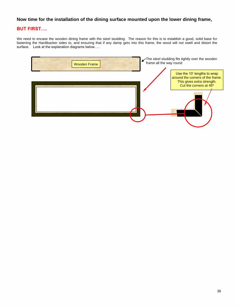
Now time for the installation of the dining surface mounted upon the lower dining frame,
BUT FIRST…. We need to encase the wooden dining frame with the steel studding. The reason for this is to establish a good, solid base for fastening the Hardibacker sides to, and ensuring that if any damp gets into this frame, the wood will not swell and distort the surface. Look at the explanation diagrams below…..
The steel studding fits tightly over the wooden frame all the way round
Wooden Frame
Use the 10’ lengths to wrap around the corners of the frame.
This gives extra strength. Cut the corners at 45º
39
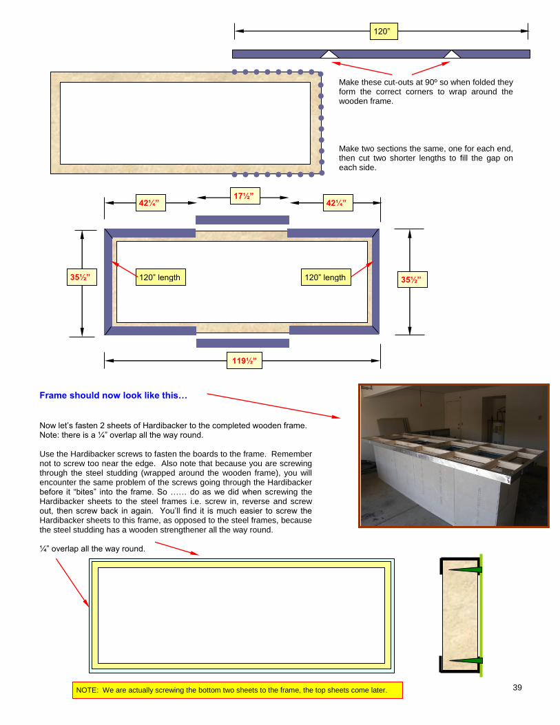
Make these cut-outs at 90º so when folded they form the correct corners to wrap around the wooden frame. Make two sections the same, one for each end, then cut two shorter lengths to fill the gap on each side.
Frame should now look like this… Now let’s fasten 2 sheets of Hardibacker to the completed wooden frame. Note: there is a ¼” overlap all the way round. Use the Hardibacker screws to fasten the boards to the frame. Remember not to screw too near the edge. Also note that because you are screwing through the steel studding (wrapped around the wooden frame), you will encounter the same problem of the screws going through the Hardibacker before it “bites” into the frame. So …… do as we did when screwing the Hardibacker sheets to the steel frames i.e. screw in, reverse and screw out, then screw back in again. You’ll find it is much easier to screw the Hardibacker sheets to this frame, as opposed to the steel frames, because the steel studding has a wooden strengthener all the way round. ¼” overlap all the way round.
120”
35½” 35½”
42¼” 42¼” 17½”
120” length 120” length
119½”
NOTE: We are actually screwing the bottom two sheets to the frame, the top sheets come later.
40
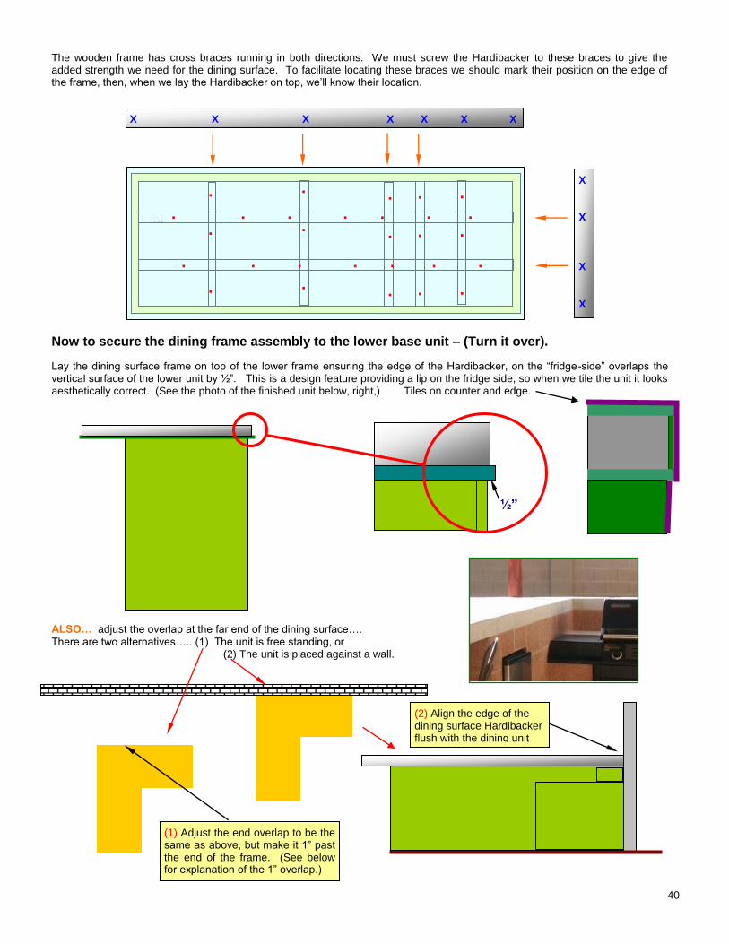
The wooden frame has cross braces running in both directions. We must screw the Hardibacker to these braces to give the added strength we need for the dining surface. To facilitate locating these braces we should mark their position on the edge of the frame, then, when we lay the Hardibacker on top, we’ll know their location. …
Now to secure the dining frame assembly to the lower base unit – (Turn it over).
Lay the dining surface frame on top of the lower frame ensuring the edge of the Hardibacker, on the “fridge-side” overlaps the vertical surface of the lower unit by ½”. This is a design feature providing a lip on the fridge side, so when we tile the unit it looks aesthetically correct. (See the photo of the finished unit below, right,) Tiles on counter and edge.
½”
ALSO… adjust the overlap at the far end of the dining surface….
There are two alternatives….. (1) The unit is free standing, or (2) The unit is placed against a wall.
X X X X X X X
X X X
X
(1) Adjust the end overlap to be the same as above, but make it 1” past the end of the frame. (See below for explanation of the 1” overlap.)
(2) Align the edge of the dining surface Hardibacker flush with the dining unit
. . . . . . . . . . .
. . . . . . . . . . .
. . .
. . .
. . .
. . .
. . .
41
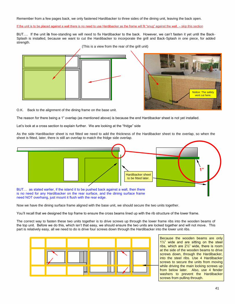
Remember from a few pages back, we only fastened Hardibacker to three sides of the dining unit, leaving the back open. If the unit is to be placed against a wall there is no need to use Hardibacker as the frame will fit “snug” against the wall. – skip this section
BUT…. If the unit is free-standing we will need to fix Hardibacker to the back. However, we can’t fasten it yet until the Back-
Splash is installed, because we want to cut the Hardibacker to incorporate the grill and Back-Splash in one piece, for added strength.
(This is a view from the rear of the grill unit) O.K. Back to the alignment of the dining frame on the base unit. The reason for there being a 1” overlap (as mentioned above) is because the end Hardibacker sheet is not yet installed. Let’s look at a cross section to explain further. We are looking at the “fridge” side As the side Hardibacker sheet is not fitted we need to add the thickness of the Hardibacker sheet to the overlap, so when the sheet is fitted, later, there is still an overlap to match the fridge side overlap. BUT… as stated earlier, if the island it to be pushed back against a wall, then there is no need for any Hardibacker on the rear surface, and the dining surface frame need NOT overhang, just mount it flush with the rear edge. Now we have the dining surface frame aligned with the base unit, we should secure the two units together. You’ll recall that we designed the top frame to ensure the cross beams lined up with the rib structure of the lower frame. The correct way to fasten these two units together is to drive screws up through the lower frame ribs into the wooden beams of the top unit. Before we do this, which isn’t that easy, we should ensure the two units are locked together and will not move. This part is relatively easy, all we need to do is drive four screws down through the Hardibacker into the lower unit ribs.
Hardibacker sheet to be fitted later.
1”
Because the wooden beams are only 1½” wide and are sitting on the steel ribs, which are 2½” wide, there is room at the side of the wooden beams to drive screws down, through the Hardibacker, into the steel ribs. Use 4 Hardibacker screws to secure the units from moving while driving the main locking screws up from below later. Also, use 4 fender washers to prevent the Hardibacker screws from pulling through.
Notice: The safety vent cut here.
42
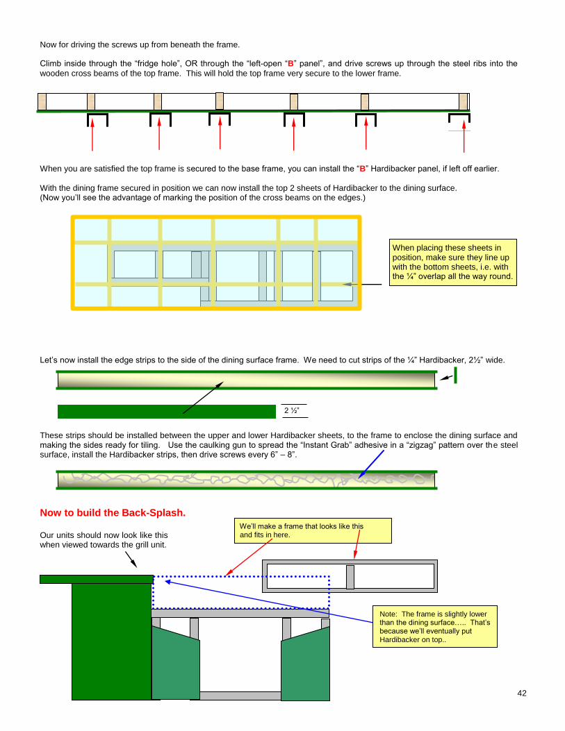
Now for driving the screws up from beneath the frame. Climb inside through the “fridge hole”, OR through the “left-open “B” panel”, and drive screws up through the steel ribs into the
wooden cross beams of the top frame. This will hold the top frame very secure to the lower frame. When you are satisfied the top frame is secured to the base frame, you can install the “B” Hardibacker panel, if left off earlier.
With the dining frame secured in position we can now install the top 2 sheets of Hardibacker to the dining surface. (Now you’ll see the advantage of marking the position of the cross beams on the edges.)
Let’s now install the edge strips to the side of the dining surface frame. We need to cut strips of the ¼” Hardibacker, 2½” wide.
These strips should be installed between the upper and lower Hardibacker sheets, to the frame to enclose the dining surface and making the sides ready for tiling. Use the caulking gun to spread the “Instant Grab” adhesive in a “zigzag” pattern over the steel surface, install the Hardibacker strips, then drive screws every 6” – 8”.
Now to build the Back-Splash. Our units should now look like this when viewed towards the grill unit.
When placing these sheets in position, make sure they line up with the bottom sheets, i.e. with the ¼” overlap all the way round.
We’ll make a frame that looks like this and fits in here. .
2 ½”
Note: The frame is slightly lower than the dining surface….. That’s because we’ll eventually put Hardibacker on top..
43
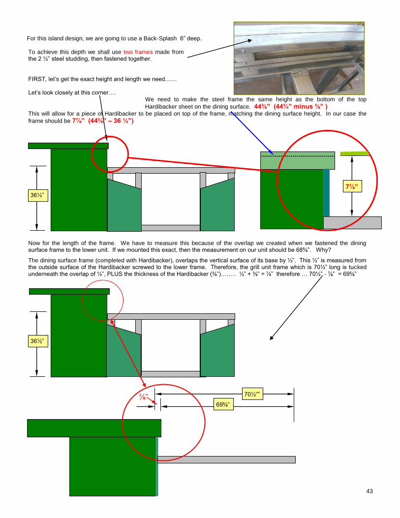
For this island design, we are going to use a Back-Splash 6” deep. To achieve this depth we shall use two frames made from the 2 ½” steel studding, then fastened together. FIRST, let’s get the exact height and length we need…… Let’s look closely at this corner….
We need to make the steel frame the same height as the bottom of the top
Hardibacker sheet on the dining surface. 44⅜” (44¾” minus ⅜” ) This will allow for a piece of Hardibacker to be placed on top of the frame, matching the dining surface height. In our case the
frame should be 7⅞” (44⅜” – 36 ½”)
Now for the length of the frame. We have to measure this because of the overlap we created when we fastened the dining surface frame to the lower unit. If we mounted this exact, then the measurement on our unit should be 68⅝”. Why?
The dining surface frame (completed with Hardibacker), overlaps the vertical surface of its base by ½”. This ½” is measured from the outside surface of the Hardibacker screwed to the lower frame. Therefore, the grill unit frame which is 70½” long is tucked underneath the overlap of ½”, PLUS the thickness of the Hardibacker (⅜”)…….. ½” + ⅜” = ⅞” therefore … 70½” - ⅞” = 69⅝”
⅞”
7⅞”
69⅝”
70½””
36½”
36½”
44
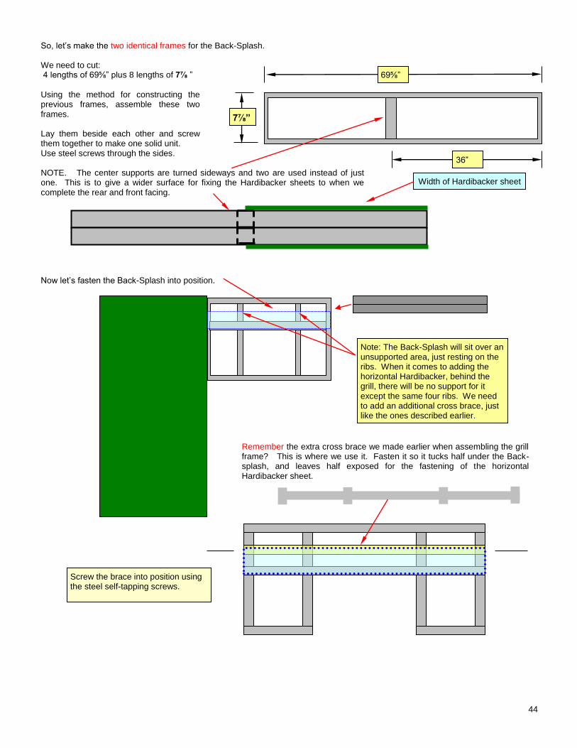
So, let’s make the two identical frames for the Back-Splash. We need to cut: 4 lengths of 69⅝” plus 8 lengths of 7⅞ ”
Using the method for constructing the previous frames, assemble these two frames. Lay them beside each other and screw them together to make one solid unit. Use steel screws through the sides. NOTE. The center supports are turned sideways and two are used instead of just one. This is to give a wider surface for fixing the Hardibacker sheets to when we complete the rear and front facing. Now let’s fasten the Back-Splash into position.
Remember the extra cross brace we made earlier when assembling the grill frame? This is where we use it. Fasten it so it tucks half under the Back-splash, and leaves half exposed for the fastening of the horizontal Hardibacker sheet.
69⅝”
7⅞”
36”
Width of Hardibacker sheet
Note: The Back-Splash will sit over an unsupported area, just resting on the ribs. When it comes to adding the horizontal Hardibacker, behind the grill, there will be no support for it except the same four ribs. We need to add an additional cross brace, just like the ones described earlier.
Screw the brace into position using the steel self-tapping screws.
45
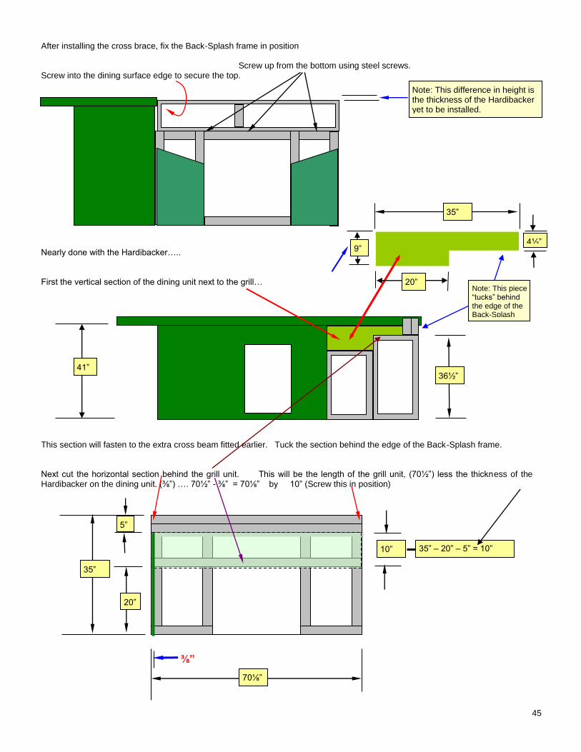
After installing the cross brace, fix the Back-Splash frame in position Screw up from the bottom using steel screws. Screw into the dining surface edge to secure the top. Nearly done with the Hardibacker….. First the vertical section of the dining unit next to the grill…
This section will fasten to the extra cross beam fitted earlier. Tuck the section behind the edge of the Back-Splash frame. Next cut the horizontal section behind the grill unit. This will be the length of the grill unit, (70½”) less the thickness of the Hardibacker on the dining unit. (⅜”) …. 70½” - ⅜” = 70⅛” by 10” (Screw this in position)
Note: This difference in height is the thickness of the Hardibacker yet to be installed.
35”
20”
5”
10”
35”
4½”
41” 36½”
70⅛””
⅜”
Note: This piece “tucks” behind the edge of the Back-Splash
35” – 20” – 5” = 10”
9”
20”
46
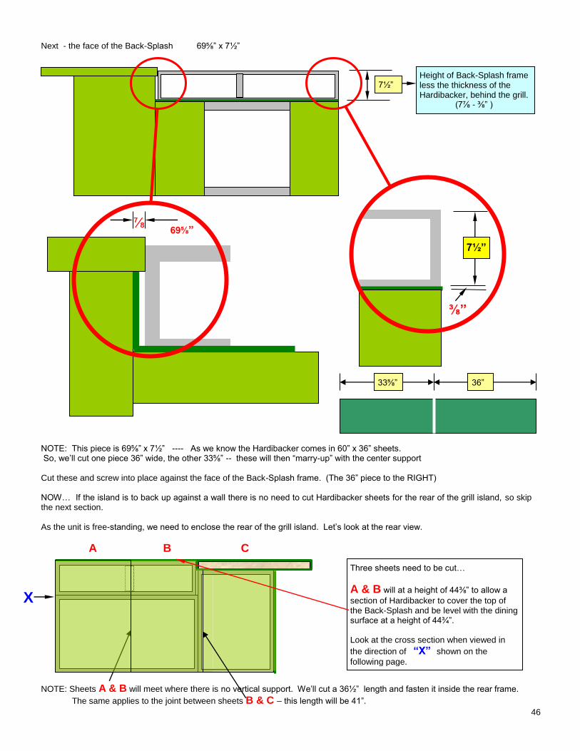
Next - the face of the Back-Splash 69⅝” x 7½”
NOTE: This piece is 69⅝” x 7½” ---- As we know the Hardibacker comes in 60” x 36” sheets. So, we’ll cut one piece 36” wide, the other 33⅝” -- these will then “marry-up” with the center support Cut these and screw into place against the face of the Back-Splash frame. (The 36” piece to the RIGHT) NOW… If the island is to back up against a wall there is no need to cut Hardibacker sheets for the rear of the grill island, so skip the next section. As the unit is free-standing, we need to enclose the rear of the grill island. Let’s look at the rear view.
A B C
NOTE: Sheets A & B will meet where there is no vertical support. We’ll cut a 36½” length and fasten it inside the rear frame.
The same applies to the joint between sheets B & C – this length will be 41”.
7½” Height of Back-Splash frame less the thickness of the Hardibacker, behind the grill. (7⅞ - ⅜” )
7½”
69⅝” ⅞
Three sheets need to be cut…
A & B will at a height of 44⅜” to allow a
section of Hardibacker to cover the top of the Back-Splash and be level with the dining surface at a height of 44¾”. Look at the cross section when viewed in
the direction of “X” shown on the
following page.
X
⅜”
36” 33⅝”
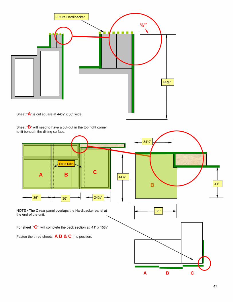
47
Sheet “A” is cut square at 44⅜” x 36” wide.
Sheet “B” will need to have a cut-out in the top right corner
to fit beneath the dining surface. NOTE> The C rear panel overlaps the Hardibacker panel at the end of the unit.
For sheet “C” will complete the back section at 41” x 15¾”
Fasten the three sheets A B & C into position.
A B C
44⅜”
⅜”
41”
44⅜”
34½”
36” 36”
36”
A B C
B
24⅞”
Future Hardibacker
Extra Ribs
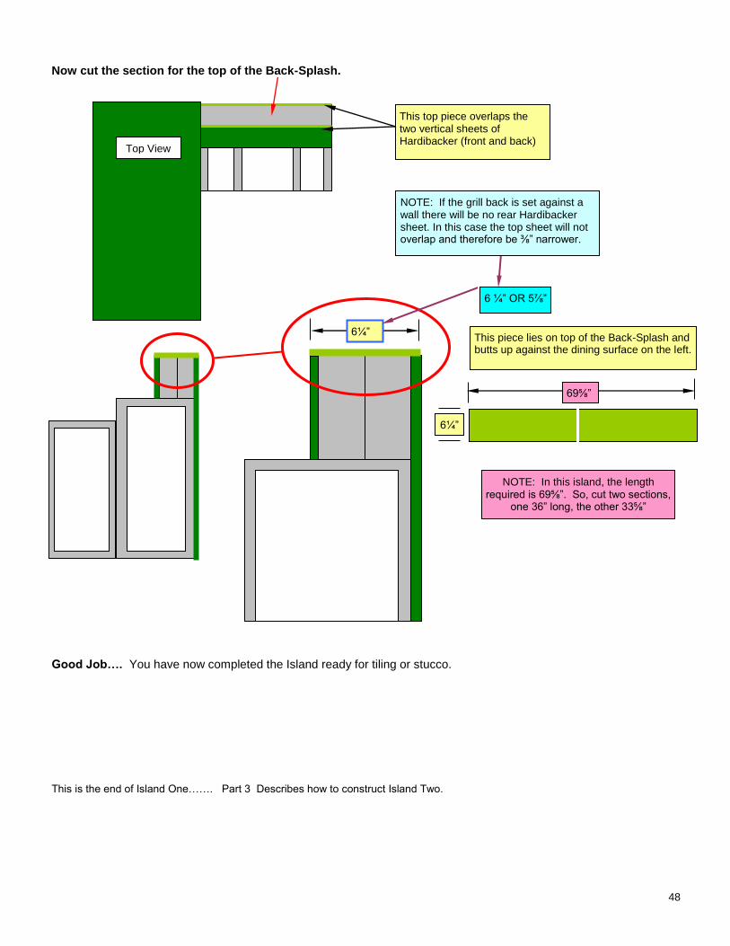
48
Now cut the section for the top of the Back-Splash.
Good Job…. You have now completed the Island ready for tiling or stucco. This is the end of Island One……. Part 3 Describes how to construct Island Two.
This top piece overlaps the two vertical sheets of Hardibacker (front and back)
6¼”
6 ¼” OR 5⅞”
This piece lies on top of the Back-Splash and butts up against the dining surface on the left.
69⅝”
NOTE: In this island, the length required is 69⅝”. So, cut two sections,
one 36” long, the other 33⅝”
NOTE: If the grill back is set against a wall there will be no rear Hardibacker sheet. In this case the top sheet will not overlap and therefore be ⅜” narrower.
Top View
6¼”
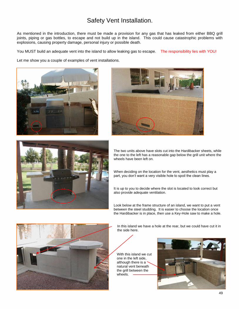
49
Safety Vent Installation.
As mentioned in the introduction, there must be made a provision for any gas that has leaked from either BBQ grill joints, piping or gas bottles, to escape and not build up in the island. This could cause catastrophic problems with explosions, causing property damage, personal injury or possible death. You MUST build an adequate vent into the island to allow leaking gas to escape. The responsibility lies with YOU! Let me show you a couple of examples of vent installations.
The two units above have slots cut into the Hardibacker sheets, while the one to the left has a reasonable gap below the grill unit where the wheels have been left on.
When deciding on the location for the vent, aesthetics must play a part, you don’t want a very visible hole to spoil the clean lines.
It is up to you to decide where the slot is located to look correct but also provide adequate ventilation.
Look below at the frame structure of an island, we want to put a vent between the steel studding. It is easier to choose the location once the Hardibacker is in place, then use a Key-Hole saw to make a hole.
In this island we have a hole at the rear, but we could have cut it in the side here.
With this island we cut one in the left side, although there is a natural vent beneath the grill between the wheels.
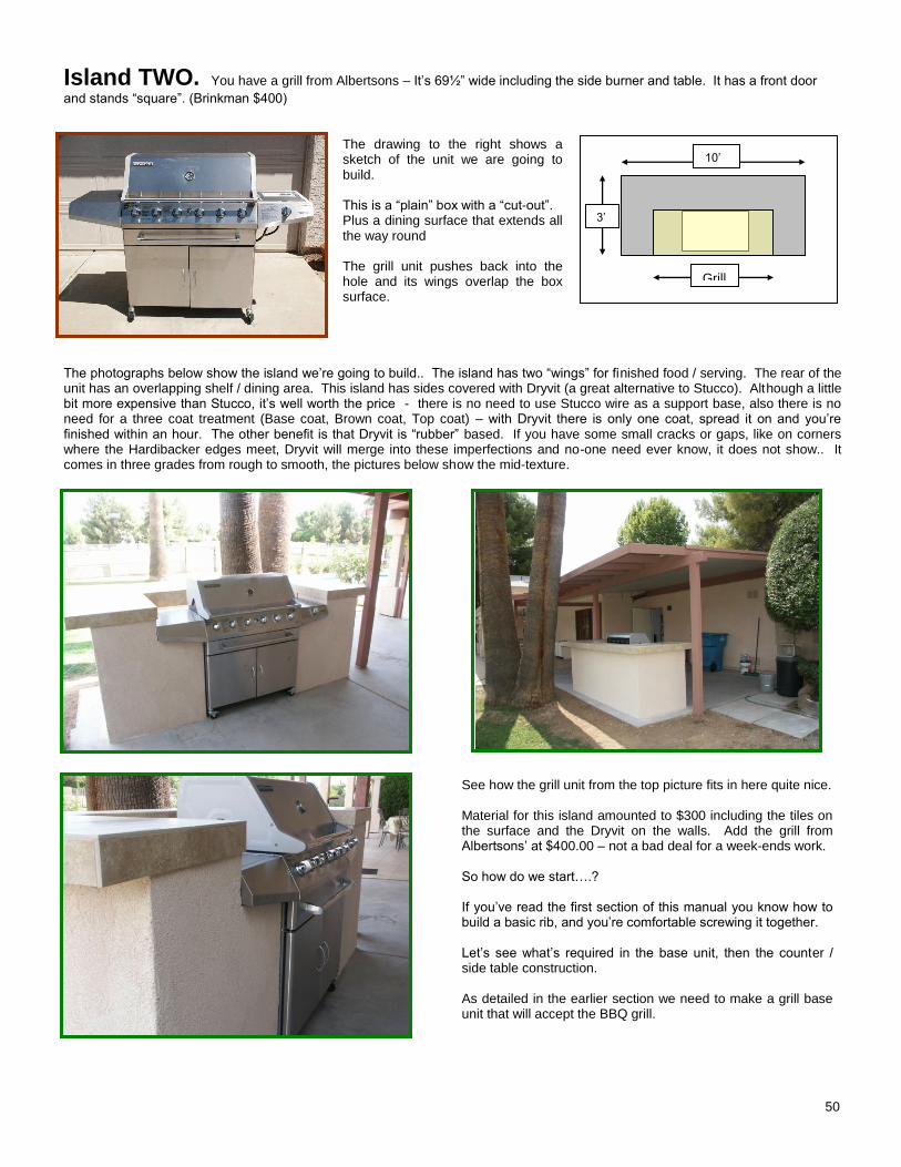
50
Island TWO. You have a grill from Albertsons – It’s 69½” wide including the side burner and table. It has a front door
and stands “square”. (Brinkman $400)
The drawing to the right shows a sketch of the unit we are going to build. This is a “plain” box with a “cut-out”. Plus a dining surface that extends all the way round The grill unit pushes back into the hole and its wings overlap the box surface.
The photographs below show the island we’re going to build.. The island has two “wings” for finished food / serving. The rear of the unit has an overlapping shelf / dining area. This island has sides covered with Dryvit (a great alternative to Stucco). Although a little bit more expensive than Stucco, it’s well worth the price - there is no need to use Stucco wire as a support base, also there is no need for a three coat treatment (Base coat, Brown coat, Top coat) – with Dryvit there is only one coat, spread it on and you’re finished within an hour. The other benefit is that Dryvit is “rubber” based. If you have some small cracks or gaps, like on corners where the Hardibacker edges meet, Dryvit will merge into these imperfections and no-one need ever know, it does not show.. It comes in three grades from rough to smooth, the pictures below show the mid-texture.
See how the grill unit from the top picture fits in here quite nice. Material for this island amounted to $300 including the tiles on the surface and the Dryvit on the walls. Add the grill from Albertsons’ at $400.00 – not a bad deal for a week-ends work. So how do we start….? If you’ve read the first section of this manual you know how to build a basic rib, and you’re comfortable screwing it together. Let’s see what’s required in the base unit, then the counter / side table construction. As detailed in the earlier section we need to make a grill base unit that will accept the BBQ grill.
10’
3’
Grill
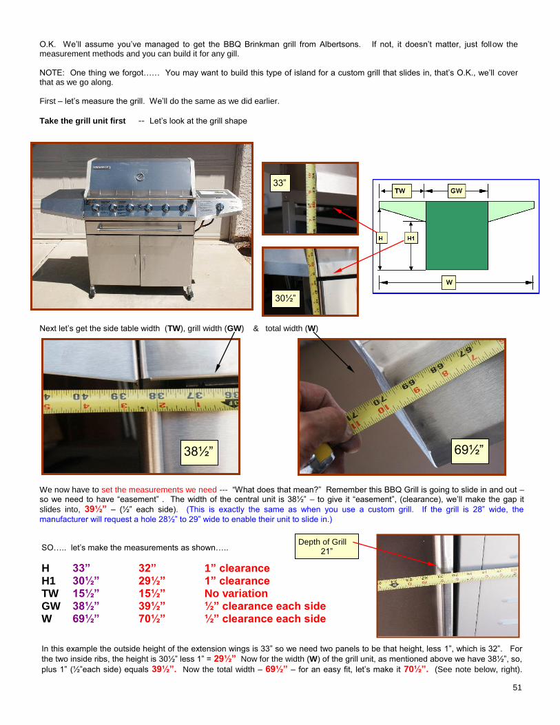
51
O.K. We’ll assume you’ve managed to get the BBQ Brinkman grill from Albertsons. If not, it doesn’t matter, just follow the measurement methods and you can build it for any gill. NOTE: One thing we forgot…… You may want to build this type of island for a custom grill that slides in, that’s O.K., we’ll cover that as we go along. First – let’s measure the grill. We’ll do the same as we did earlier.
Take the grill unit first -- Let’s look at the grill shape
.
Next let’s get the side table width (TW), grill width (GW) & total width (W)
We now have to set the measurements we need --- “What does that mean?” Remember this BBQ Grill is going to slide in and out – so we need to have “easement” . The width of the central unit is 38½” – to give it “easement”, (clearance), we’ll make the gap it
slides into, 39½” – (½” each side). (This is exactly the same as when you use a custom grill. If the grill is 28” wide, the
manufacturer will request a hole 28½” to 29” wide to enable their unit to slide in.) SO….. let’s make the measurements as shown…..
H 33” 32” 1” clearance H1 30½” 29½” 1” clearance TW 15½” 15½” No variation GW 38½” 39½” ½” clearance each side W 69½” 70½” ½” clearance each side In this example the outside height of the extension wings is 33” so we need two panels to be that height, less 1”, which is 32”. For
the two inside ribs, the height is 30½” less 1” = 29½” Now for the width (W) of the grill unit, as mentioned above we have 38½”, so,
plus 1” (½”each side) equals 39½”. Now the total width – 69½” – for an easy fit, let’s make it 70½”. (See note below, right).
38½”
Depth of Grill 21”
33”
30½”
69½”
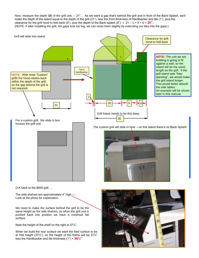
52
Now, measure the depth (D) of the grill unit, -- 21”. . As we want a gap that’s behind the grill and in front of the Back-Splash, we’ll
make the depth of the island equal to the depth of the grill (21”), less the front thickness of Hardibacker and tile (1”), plus the
clearance for the grill hood to fold back (9”), plus the depth of the Back-splash (6”) = 21 – 1 + 9 + 6 = 35”. (NOTE: If after installing the grill, the gaps look too big, we can close them slightly by extending our tiles into the gaps.) Grill will slide into island
Grill frame needs to be this deep For a custom grill, the slide in box houses the grill unit.
The custom grill will slide in here – on this island there’s no Back-Splash O.K back to the $400 grill…. The side shelves are approximately 4” high --- Look at the photo for explanation. We need to make the surface behind the grill to be the same height as the side shelves, so when the grill unit is pushed back into position we have a continual flat surface. Note the height of the shelf on the right is 37½”. When we build the rear surface we want the tiled surface to be at that height (37½”), so the height of the frame will be 37½”
less the Hardibacker and tile thickness (1”) = 36½”
Clearance for grill hood to fold back
20 9 6
1
21
Tile & Hardibacker
.
NOTE: With most “Custom” grills the hood rotates back within the depth of the grill, so the gap behind the grill is not required.
. NOTE: The unit we are
building is going to fit against a wall, so the island will be the same length as the grill. If the grill island was “free-standing”, we would make the grill island longer. This would better absorb the side tables. An example will be shown later in this manual.
35
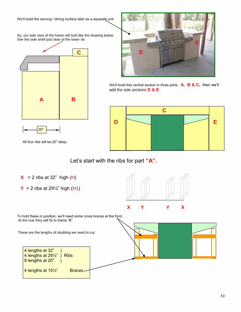
53
We’ll build the serving / dining surface later as a separate unit So, our side view of the frame will look like the drawing below. See the side shelf just clear of the lower rib
We’ll build this central section in three parts. A, B & C, then we’ll
add the side sections D & E
All four ribs will be 20” deep,
Let’s start with the ribs for part “A”.
X = 2 ribs at 32” high (H)
Y = 2 ribs at 29½” high (H1)
X Y Y X
To hold these in position, we’ll need some cross braces at the front. At the rear they will fix to frame “B”. These are the lengths of studding we need to cut.
4 lengths at 32” ) 4 lengths at 29½” ) Ribs 8 lengths at 20” ) 4 lengths at 15½” Braces
A B
C
20”
D E
C
E
D
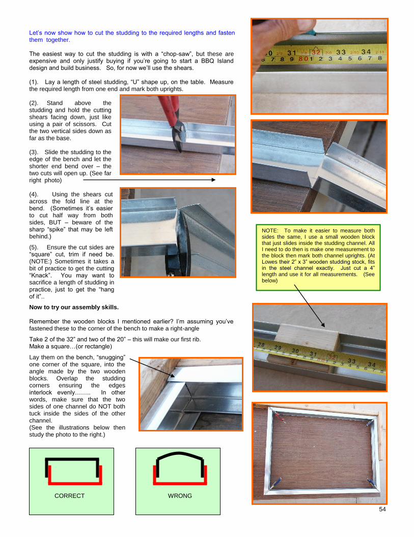
54
Let’s now show how to cut the studding to the required lengths and fasten them together. The easiest way to cut the studding is with a “chop-saw”, but these are expensive and only justify buying if you’re going to start a BBQ Island design and build business. So, for now we’ll use the shears. (1). Lay a length of steel studding, “U” shape up, on the table. Measure the required length from one end and mark both uprights. (2). Stand above the studding and hold the cutting shears facing down, just like using a pair of scissors. Cut the two vertical sides down as far as the base. (3). Slide the studding to the edge of the bench and let the shorter end bend over – the two cuts will open up. (See far right photo) (4). Using the shears cut across the fold line at the bend. (Sometimes it’s easier to cut half way from both sides, BUT – beware of the sharp “spike” that may be left behind.)
(5). Ensure the cut sides are “square” cut, trim if need be. (NOTE:) Sometimes it takes a bit of practice to get the cutting “Knack”. You may want to sacrifice a length of studding in practice, just to get the “hang of it”..
Now to try our assembly skills.
Remember the wooden blocks I mentioned earlier? I’m assuming you’ve fastened these to the corner of the bench to make a right-angle
Take 2 of the 32” and two of the 20” – this will make our first rib. Make a square…(or rectangle)
Lay them on the bench, “snugging” one corner of the square, into the angle made by the two wooden blocks. Overlap the studding corners ensuring the edges interlock evenly…….. In other words, make sure that the two sides of one channel do NOT both tuck inside the sides of the other channel. (See the illustrations below then study the photo to the right.)
Shears cutting both sides.
Cutting across the studding bend with shears.
NOTE: To make it easier to measure both sides the same, I use a small wooden block that just slides inside the studding channel. All I need to do then is make one measurement to the block then mark both channel uprights. (At Lowes their 2” x 3” wooden studding stock, fits in the steel channel exactly. Just cut a 4” length and use it for all measurements. (See below)
CORRECT WRONG
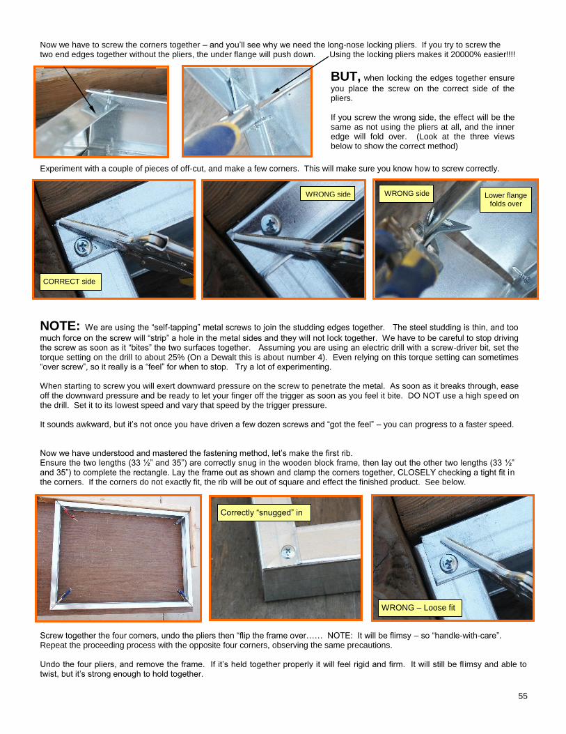
55
Now we have to screw the corners together – and you’ll see why we need the long-nose locking pliers. If you try to screw the two end edges together without the pliers, the under flange will push down. Using the locking pliers makes it 20000% easier!!!!
BUT, when locking the edges together ensure
you place the screw on the correct side of the pliers. If you screw the wrong side, the effect will be the same as not using the pliers at all, and the inner edge will fold over. (Look at the three views below to show the correct method)
Experiment with a couple of pieces of off-cut, and make a few corners. This will make sure you know how to screw correctly.
NOTE: We are using the “self-tapping” metal screws to join the studding edges together. The steel studding is thin, and too
much force on the screw will “strip” a hole in the metal sides and they will not lock together. We have to be careful to stop driving the screw as soon as it “bites” the two surfaces together. Assuming you are using an electric drill with a screw-driver bit, set the torque setting on the drill to about 25% (On a Dewalt this is about number 4). Even relying on this torque setting can sometimes “over screw”, so it really is a “feel” for when to stop. Try a lot of experimenting. When starting to screw you will exert downward pressure on the screw to penetrate the metal. As soon as it breaks through, ease off the downward pressure and be ready to let your finger off the trigger as soon as you feel it bite. DO NOT use a high speed on the drill. Set it to its lowest speed and vary that speed by the trigger pressure. It sounds awkward, but it’s not once you have driven a few dozen screws and “got the feel” – you can progress to a faster speed. Now we have understood and mastered the fastening method, let’s make the first rib. Ensure the two lengths (33 ½” and 35”) are correctly snug in the wooden block frame, then lay out the other two lengths (33 ½” and 35”) to complete the rectangle. Lay the frame out as shown and clamp the corners together, CLOSELY checking a tight fit in the corners. If the corners do not exactly fit, the rib will be out of square and effect the finished product. See below.
Screw together the four corners, undo the pliers then “flip the frame over…… NOTE: It will be flimsy – so “handle-with-care”. Repeat the proceeding process with the opposite four corners, observing the same precautions. Undo the four pliers, and remove the frame. If it’s held together properly it will feel rigid and firm. It will still be fl imsy and able to twist, but it’s strong enough to hold together.
Edges screwed without locking pliers
Edges screwed correctly using the locking pliers.
Correct side of pliers 1 Correct side of pliers 2
Correct side of pliers 3
Four side of rib squarely laid out and clamped
Clamped correctly – no gaps Bad fitting X
CORRECT side
WRONG side
WRONG side Lower flange
folds over
WRONG side
Correctly “snugged” in
WRONG – Loose fit
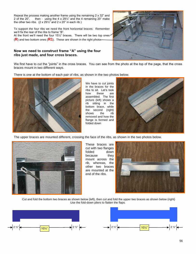
56
Repeat the process making another frame using the remaining 2 x 32” and 2 of the 20”, then - using the 4 x 29½” and the 4 remaining 20” make the other two ribs. (2 x 29½” and 2 x 20” in each rib.) To support the four ribs we need the front horizontal braces: Remember we’ll fix the rear of the ribs to frame “B”. At the front we’ll need the four 15½” braces. There will be two top ones
(R) and two bottom ones (R1). These are shown in the right photo.
Now we need to construct frame “A” using the four ribs just made, and four cross braces.
We first have to cut the “joints” in the cross braces. You can see from the photo at the top of the page, that the cross braces mount in two different ways.
There is one at the bottom of each pair of ribs, as shown in the two photos below.
We have to cut joints in the braces for the ribs to sit. Let’s look how these are assembled. The first picture (left) shows a rib sitting in the bottom brace, while the second (right) shows the rib removed and how the flange is formed and folded down
The upper braces are mounted different, crossing the face of the ribs, as shown in the two photos below.
These braces are cut with two flanges folded down because they mount across the rib, whereas, the other two braces are mounted at the end of the ribs.
Cut and fold the bottom two braces as shown below (left), then cut and fold the upper two braces as shown below (right)
Use the fold-down pliers to flatten the flaps.
Back bottom rail in position
2 ½” 2 ½” 2 ½” 2 ½” 10½” 10½”
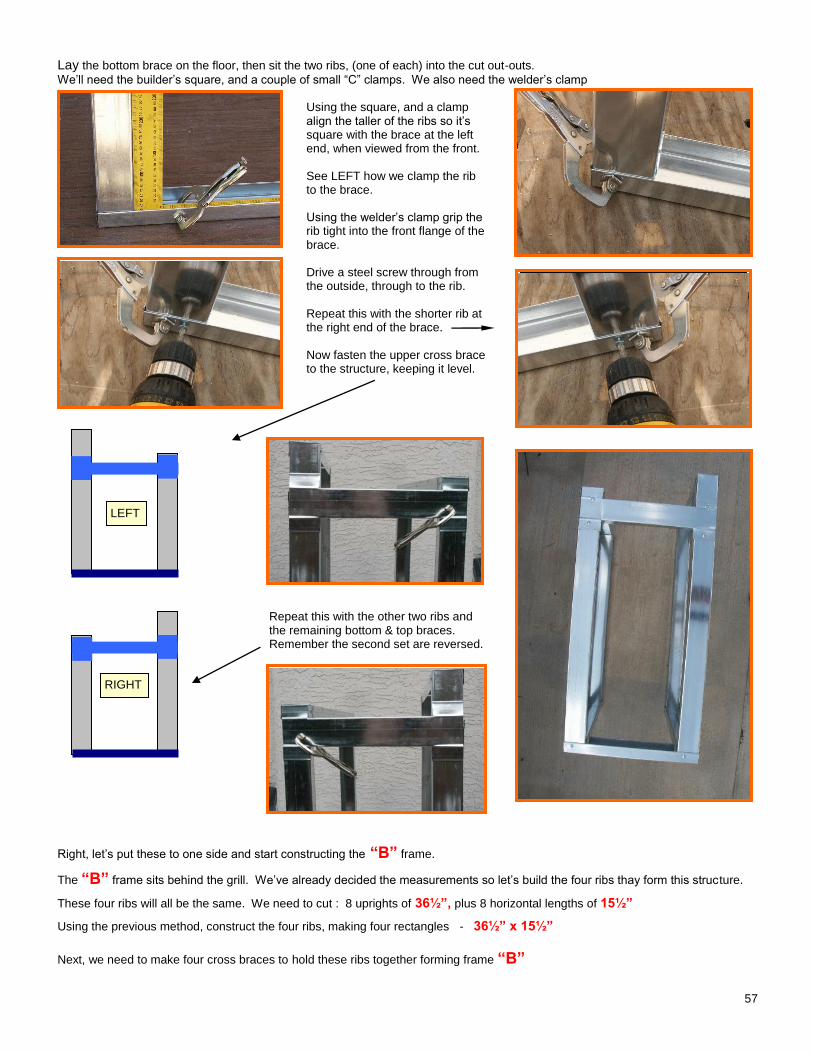
57
Lay the bottom brace on the floor, then sit the two ribs, (one of each) into the cut out-outs.
We’ll need the builder’s square, and a couple of small “C” clamps. We also need the welder’s clamp Using the square, and a clamp align the taller of the ribs so it’s square with the brace at the left end, when viewed from the front. See LEFT how we clamp the rib to the brace. Using the welder’s clamp grip the rib tight into the front flange of the brace. Drive a steel screw through from the outside, through to the rib. Repeat this with the shorter rib at the right end of the brace. Now fasten the upper cross brace to the structure, keeping it level.
Repeat this with the other two ribs and the remaining bottom & top braces. Remember the second set are reversed.
Right, let’s put these to one side and start constructing the “B” frame.
The “B” frame sits behind the grill. We’ve already decided the measurements so let’s build the four ribs thay form this structure.
These four ribs will all be the same. We need to cut : 8 uprights of 36½”, plus 8 horizontal lengths of 15½”
Using the previous method, construct the four ribs, making four rectangles - 36½” x 15½”
Next, we need to make four cross braces to hold these ribs together forming frame “B”
Rib in brace with builder’s square Welders clamp holding rib against brace
Screw left rib Screw right rib
Second set reversed
Show upper cross brace in position held with welder’s clamp
LEFT
RIGHT
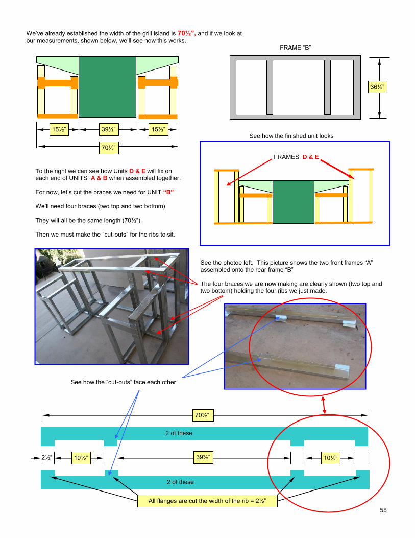
58
We’ve already established the width of the grill island is 70½”, and if we look at
our measurements, shown below, we’ll see how this works. FRAME “B”
See how the finished unit looks
FRAMES D & E
To the right we can see how Units D & E will fix on each end of UNITS A & B when assembled together.
For now, let’s cut the braces we need for UNIT “B”
We’ll need four braces (two top and two bottom)
They will all be the same length (70½”). Then we must make the “cut-outs” for the ribs to sit.
See the photoe left. This picture shows the two front frames “A” assembled onto the rear frame “B” The four braces we are now making are clearly shown (two top and two bottom) holding the four ribs we just made.
See how the “cut-outs” face each other
39½” 15½” 15½”
70½”
36½”
70½”
39½” 10½” 10½” 2½”
All flanges are cut the width of the rib = 2½”
2 of these
2 of these
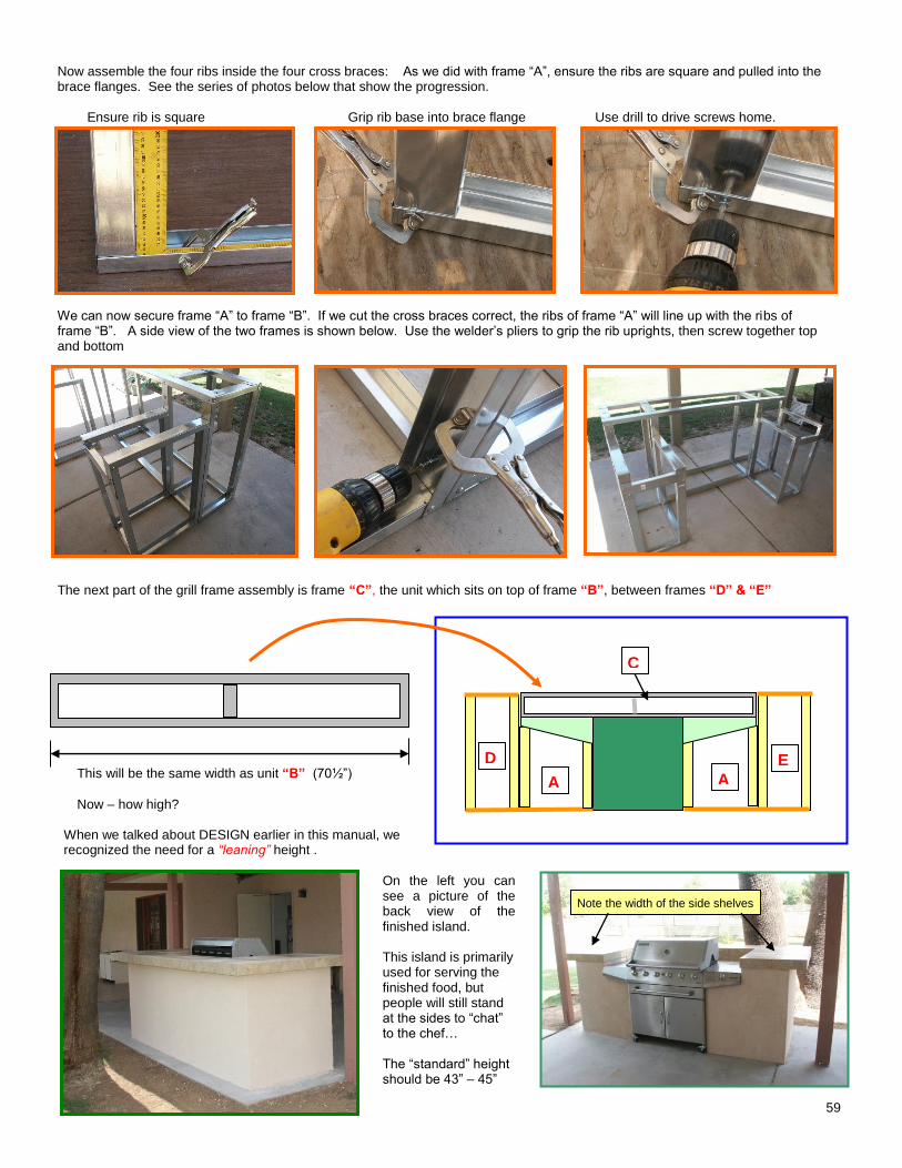
59
Now assemble the four ribs inside the four cross braces: As we did with frame “A”, ensure the ribs are square and pulled into the brace flanges. See the series of photos below that show the progression. Ensure rib is square Grip rib base into brace flange Use drill to drive screws home. We can now secure frame “A” to frame “B”. If we cut the cross braces correct, the ribs of frame “A” will line up with the ribs of frame “B”. A side view of the two frames is shown below. Use the welder’s pliers to grip the rib uprights, then screw together top and bottom The next part of the grill frame assembly is frame “C”, the unit which sits on top of frame “B”, between frames “D” & “E”
This will be the same width as unit “B” (70½”)
Now – how high?
When we talked about DESIGN earlier in this manual, we recognized the need for a “leaning” height .
On the left you can see a picture of the back view of the finished island.
This island is primarily used for serving the finished food, but people will still stand at the sides to “chat” to the chef… The “standard” height should be 43” – 45”
Builder’s square with rib in brace. Welder’s pliers gripping rib to flange Drill driving screw home.
Side view of frames joined. Screw together top and bottom.
Completed frame A & B joined
A A
D E
C
Note the width of the side shelves
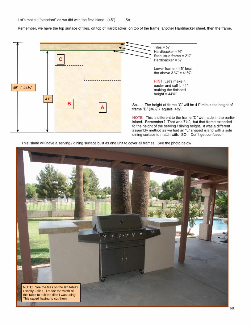
60
Let’s make it “standard” as we did with the first island. (45”) So…. Remember, we have the top surface of tiles, on top of Hardibacker, on top of the frame, another Hardibacker sheet, then the frame.
So…. The height of frame “C” will be 41” minus the height of frame “B” (36½”) equals 4½”. NOTE: This is different to the frame “C” we made in the earlier island. Remember? That was 7½”, but that frame extended to the height of the serving / dining height. It was a different assembly method as we had an “L” shaped island with a side dining surface to match with. SO.. Don’t get confused!!
This island will have a serving / dining surface built as one unit to cover all frames. See the photo below
B
C
A
Tiles = ½” Hardibacker = ⅜” Steel stud frame = 2½” Hardibacker = ⅜” Lower frame = 45” less the above 3 ¾” = 41¼”. HINT: Let’s make it easier and call it 41” making the finished height = 44¾”
45” / 44¾”
41”
NOTE: See the tiles on the left table? Exactly 2 tiles. I made the width of this table to suit the tiles I was using. This saved having to cut them!!.
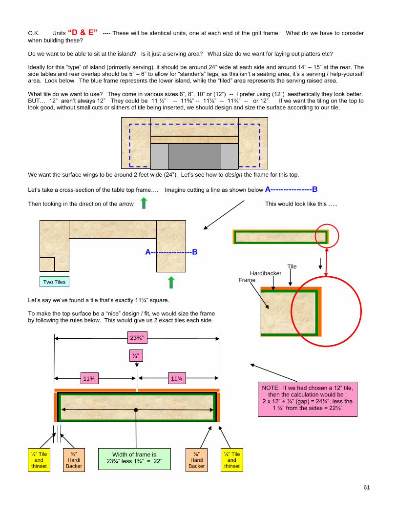
61
O.K. Units “D & E” ---- These will be identical units, one at each end of the grill frame. What do we have to consider
when building these? Do we want to be able to sit at the island? Is it just a serving area? What size do we want for laying out platters etc? Ideally for this “type” of island (primarily serving), it should be around 24” wide at each side and around 14” – 15” at the rear. The side tables and rear overlap should be 5” – 6” to allow for “stander’s” legs, as this isn’t a seating area, it’s a serving / help-yourself area. Look below. The blue frame represents the lower island, while the “tiled” area represents the serving raised area. What tile do we want to use? They come in various sizes 6”, 8”, 10” or (12”) -- I prefer using (12”) aesthetically they look better. BUT… 12” aren’t always 12” They could be 11 ½” -- 11⅝” -- 11⅞” -- 11¾” -- or 12” If we want the tiling on the top to look good, without small cuts or slithers of tile being inserted, we should design and size the surface according to our tile. We want the surface wings to be around 2 feet wide (24”). Let’s see how to design the frame for this top.
Let’s take a cross-section of the table top frame…. Imagine cutting a line as shown below A----------------B
Then looking in the direction of the arrow This would look like this …..
A----------------B
Tile Hardibacker Frame
Let’s say we’ve found a tile that’s exactly 11¾” square. To make the top surface be a “nice” design / fit, we would size the frame by following the rules below. This would give us 2 exact tiles each side.
11¾”
11¾”
¼”
½” Tile and
thinset
½” Tile and
thinset
⅜” Hardi
Backer
⅜” Hardi
Backer
Width of frame is 23¾” less 1¾” = 22”
23¾”
Two Tiles
NOTE: If we had chosen a 12” tile, then the calculation would be :
2 x 12” + ¼” (gap) = 24¼”, less the 1 ¾” from the sides = 22½”
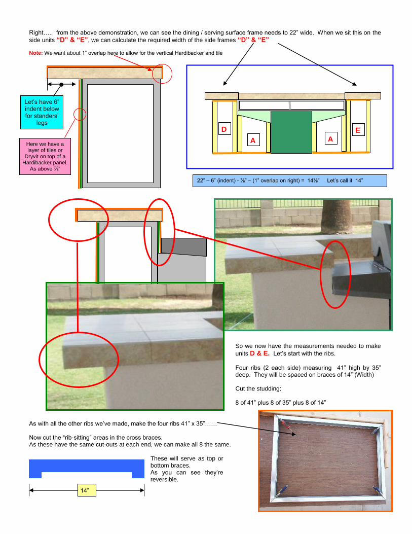
62
Right….. from the above demonstration, we can see the dining / serving surface frame needs to 22” wide. When we sit this on the
side units “D” & “E”, we can calculate the required width of the side frames “D” & “E” Note: We want about 1” overlap here to allow for the vertical Hardibacker and tile
So we now have the measurements needed to make
units D & E. Let’s start with the ribs.
Four ribs (2 each side) measuring 41” high by 35” deep. They will be spaced on braces of 14” (Width) Cut the studding: 8 of 41” plus 8 of 35” plus 8 of 14”
As with all the other ribs we’ve made, make the four ribs 41” x 35”…… Now cut the “rib-sitting” areas in the cross braces. As these have the same cut-outs at each end, we can make all 8 the same.
These will serve as top or bottom braces. As you can see they’re reversible.
A A
D E
Let’s have 6” indent below for standers’
legs
Here we have a layer of tiles or
Dryvit on top of a Hardibacker panel.
As above ⅞”
22” – 6” (indent) - ⅞” – (1” overlap on right) = 14⅛” Let’s call it 14”
14”
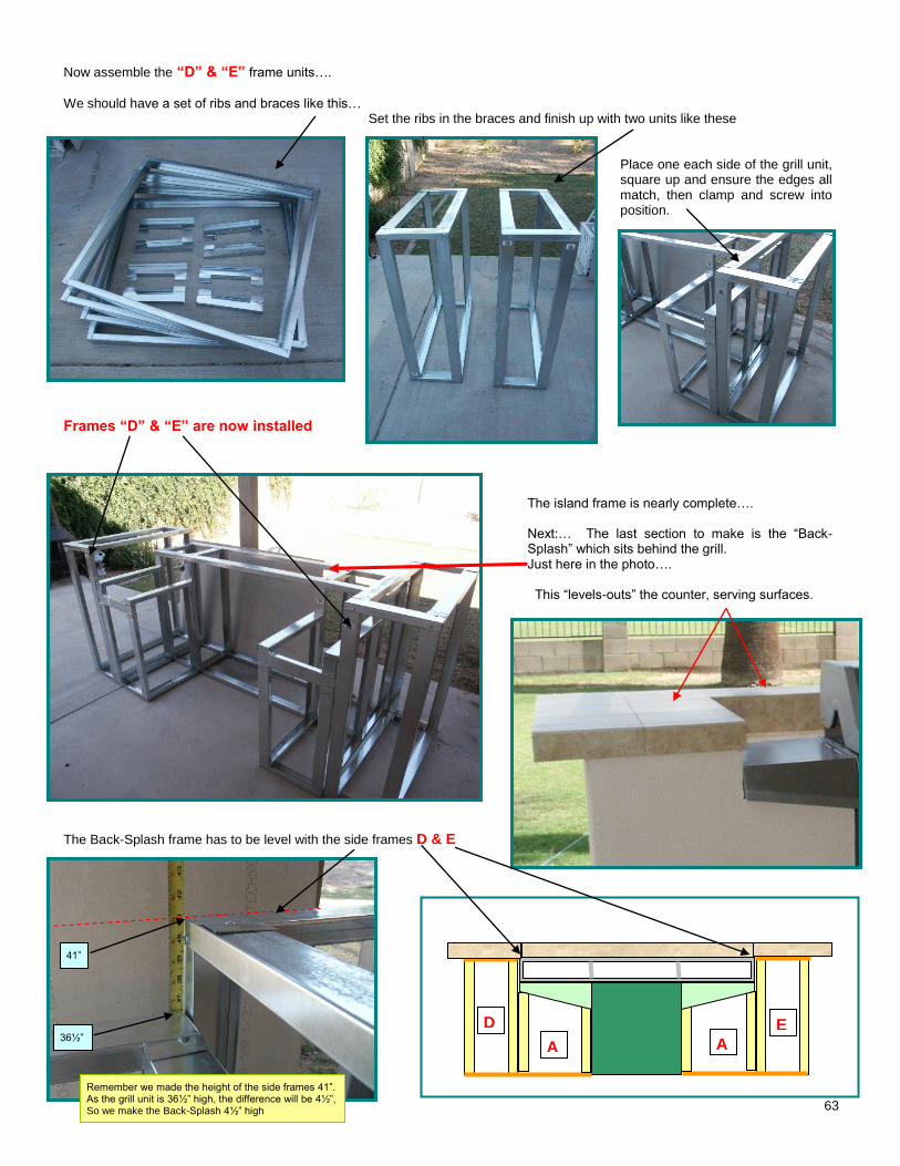
63
Now assemble the “D” & “E” frame units….
We should have a set of ribs and braces like this…
Set the ribs in the braces and finish up with two units like these .
Place one each side of the grill unit, square up and ensure the edges all match, then clamp and screw into position.
Frames “D” & “E” are now installed
The island frame is nearly complete….
Next:… The last section to make is the “Back-Splash” which sits behind the grill. Just here in the photo…. This “levels-outs” the counter, serving surfaces.
The Back-Splash frame has to be level with the side frames D & E
A A
D E
Remember we made the height of the side frames 41”. As the grill unit is 36½” high, the difference will be 4½”, So we make the Back-Splash 4½” high
36½”
41”
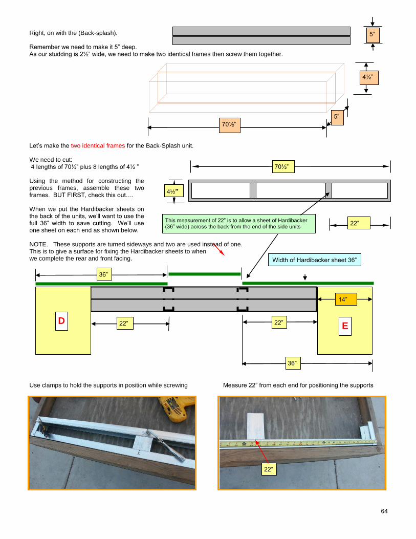
64
Right, on with the (Back-splash). Remember we need to make it 5” deep. As our studding is 2½” wide, we need to make two identical frames then screw them together. Let’s make the two identical frames for the Back-Splash unit. We need to cut: 4 lengths of 70½” plus 8 lengths of 4½ ” Using the method for constructing the previous frames, assemble these two frames. BUT FIRST, check this out…. When we put the Hardibacker sheets on the back of the units, we’ll want to use the full 36” width to save cutting. We’ll use one sheet on each end as shown below. NOTE. These supports are turned sideways and two are used instead of one. This is to give a surface for fixing the Hardibacker sheets to when we complete the rear and front facing. Use clamps to hold the supports in position while screwing Measure 22” from each end for positioning the supports
70½”
5”
5”
4½”
70½”
4½”
22”
Width of Hardibacker sheet 36”
14”
22”
This measurement of 22” is to allow a sheet of Hardibacker (36” wide) across the back from the end of the side units
36”
22”
D E
36”
22”
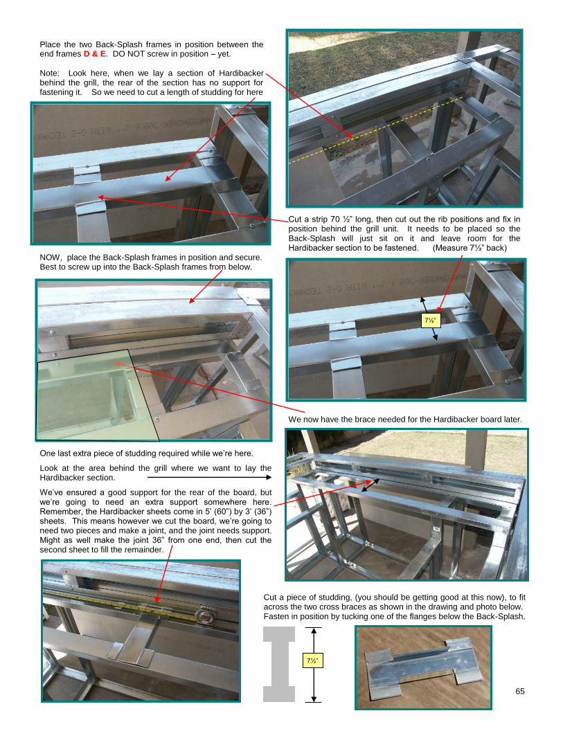
65
Place the two Back-Splash frames in position between the end frames D & E. DO NOT screw in position – yet.
Note: Look here, when we lay a section of Hardibacker behind the grill, the rear of the section has no support for fastening it. So we need to cut a length of studding for here
Cut a strip 70 ½” long, then cut out the rib positions and fix in position behind the grill unit. It needs to be placed so the Back-Splash will just sit on it and leave room for the Hardibacker section to be fastened. (Measure 7½” back)
NOW, place the Back-Splash frames in position and secure. Best to screw up into the Back-Splash frames from below.
We now have the brace needed for the Hardibacker board later.
One last extra piece of studding required while we’re here.
Look at the area behind the grill where we want to lay the Hardibacker section.
We’ve ensured a good support for the rear of the board, but we’re going to need an extra support somewhere here. Remember, the Hardibacker sheets come in 5’ (60”) by 3’ (36”) sheets. This means however we cut the board, we’re going to need two pieces and make a joint, and the joint needs support. Might as well make the joint 36” from one end, then cut the second sheet to fill the remainder.
Cut a piece of studding, (you should be getting good at this now), to fit across the two cross braces as shown in the drawing and photo below. Fasten in position by tucking one of the flanges below the Back-Splash.
7½”
7½”
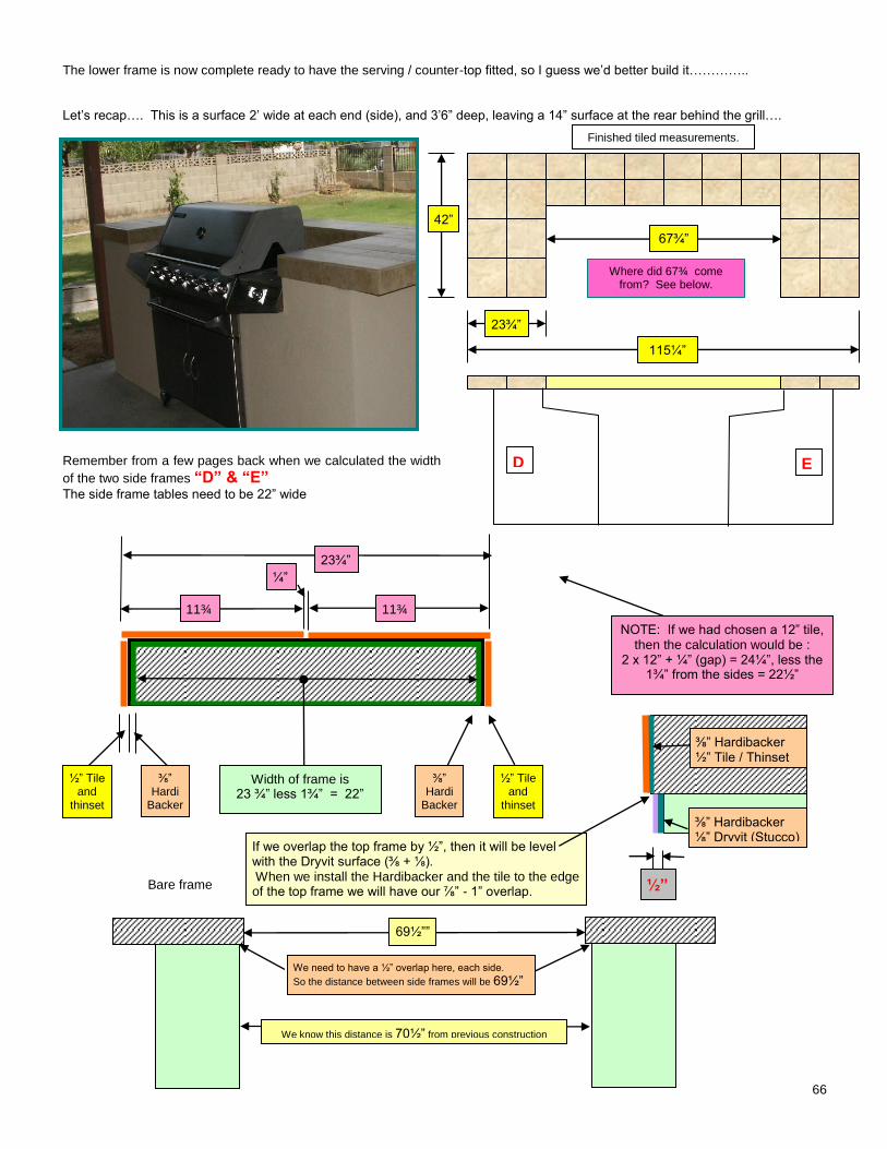
66
The lower frame is now complete ready to have the serving / counter-top fitted, so I guess we’d better build it………….. Let’s recap…. This is a surface 2’ wide at each end (side), and 3’6” deep, leaving a 14” surface at the rear behind the grill….
Remember from a few pages back when we calculated the width
of the two side frames “D” & “E” The side frame tables need to be 22” wide Bare frame
23¾”
42”
67¾”
115¼”
D E
11¾”
11¾”
¼”
½” Tile and
thinset
½” Tile and
thinset
⅜” Hardi
Backer
⅜” Hardi
Backer
Width of frame is 23 ¾” less 1¾” = 22”
23¾”
NOTE: If we had chosen a 12” tile, then the calculation would be :
2 x 12” + ¼” (gap) = 24¼”, less the 1¾” from the sides = 22½”
Where did 67¾ come from? See below.
We know this distance is 70½” from previous construction
We need to have a ½” overlap here, each side.
So the distance between side frames will be 69½”
⅜” Hardibacker ⅛” Dryvit (Stucco)
⅜” Hardibacker ½” Tile / Thinset
If we overlap the top frame by ½”, then it will be level with the Dryvit surface (⅜ + ⅛). When we install the Hardibacker and the tile to the edge of the top frame we will have our ⅞” - 1” overlap. ½”
69½””
Finished tiled measurements.
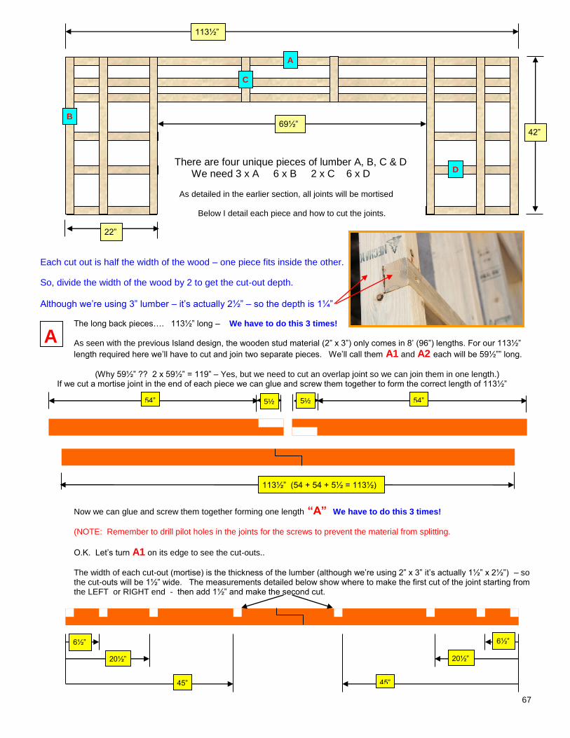
67
There are four unique pieces of lumber A, B, C & D We need 3 x A 6 x B 2 x C 6 x D
As detailed in the earlier section, all joints will be mortised Below I detail each piece and how to cut the joints.
Each cut out is half the width of the wood – one piece fits inside the other.
So, divide the width of the wood by 2 to get the cut-out depth. Although we’re using 3” lumber – it’s actually 2½” – so the depth is 1¼”
The long back pieces…. 113½” long – We have to do this 3 times!
As seen with the previous Island design, the wooden stud material (2” x 3”) only comes in 8’ (96”) lengths. For our 113½”
length required here we’ll have to cut and join two separate pieces. We’ll call them A1 and A2 each will be 59½”” long.
(Why 59½” ?? 2 x 59½” = 119” – Yes, but we need to cut an overlap joint so we can join them in one length.)
If we cut a mortise joint in the end of each piece we can glue and screw them together to form the correct length of 113½”
Now we can glue and screw them together forming one length “A” We have to do this 3 times! (NOTE: Remember to drill pilot holes in the joints for the screws to prevent the material from splitting.
O.K. Let’s turn A1 on its edge to see the cut-outs..
The width of each cut-out (mortise) is the thickness of the lumber (although we’re using 2” x 3” it’s actually 1½” x 2½”) – so the cut-outs will be 1½” wide. The measurements detailed below show where to make the first cut of the joint starting from the LEFT or RIGHT end - then add 1½” and make the second cut.
113½”
69½”
22”
42”
A
B
C
D
A
20½” 20½”
45” 45”
6½” 6½”
113½” (54 + 54 + 5½ = 113½)
5½ 5½ 54” 54”
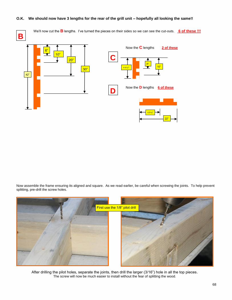
68
O.K. We should now have 3 lengths for the rear of the grill unit – hopefully all looking the same!!
We’ll now cut the B lengths. I’ve turned the pieces on their sides so we can see the cut-outs. 6 of these !!!
Now the C lengths 2 of these
Now the D lengths 6 of these
Now assemble the frame ensuring its aligned and square. As we read earlier, be careful when screwing the joints. To help prevent splitting, pre-drill the screw holes.
After drilling the pilot holes, separate the joints, then drill the larger (3/16”) hole in all the top pieces. The screw will now be much easier to install without the fear of splitting the wood.
B
6”
42”
10”
20”
30”
C 11½” 10”
6”
D
12½”
22”
First use the 1/8” pilot drill
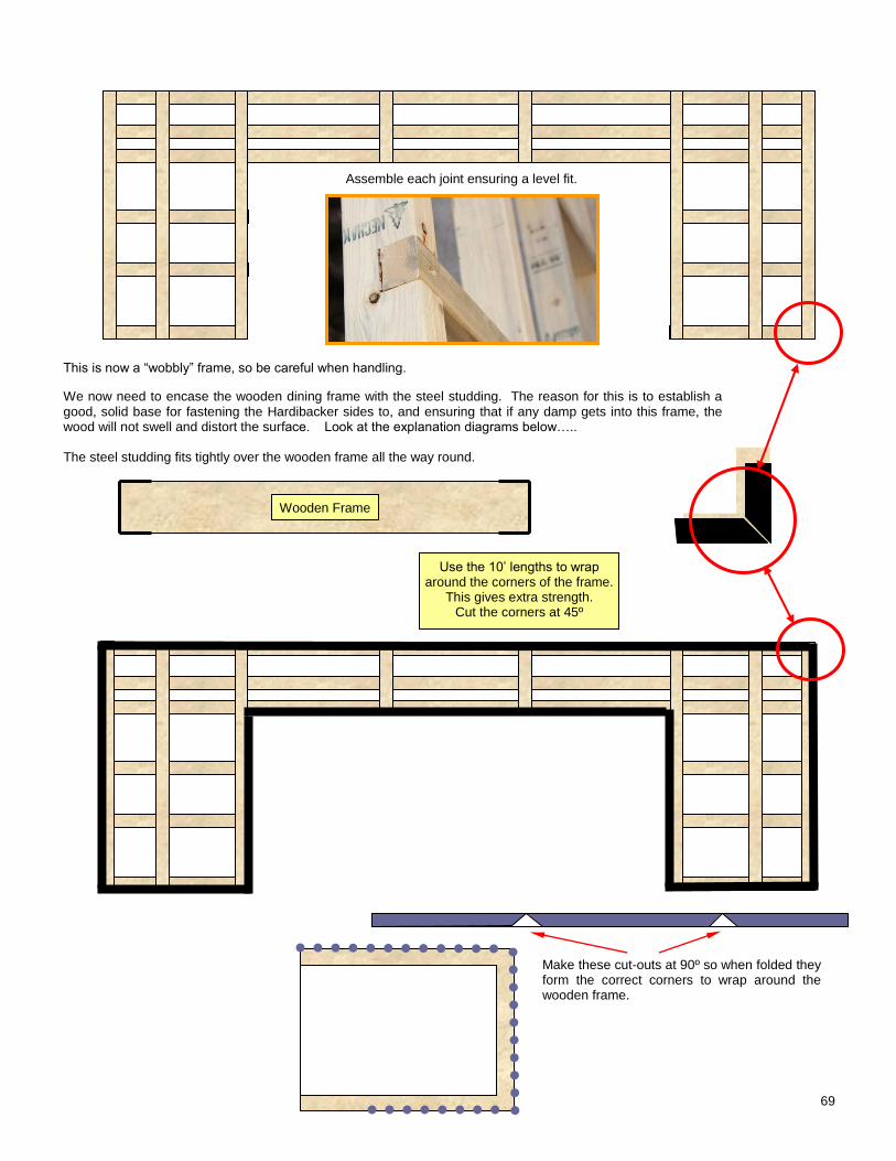
69
Assemble each joint ensuring a level fit.
This is now a “wobbly” frame, so be careful when handling.
We now need to encase the wooden dining frame with the steel studding. The reason for this is to establish a good, solid base for fastening the Hardibacker sides to, and ensuring that if any damp gets into this frame, the wood will not swell and distort the surface. Look at the explanation diagrams below….. The steel studding fits tightly over the wooden frame all the way round.
Make these cut-outs at 90º so when folded they form the correct corners to wrap around the wooden frame.
Wooden Frame
Use the 10’ lengths to wrap around the corners of the frame.
This gives extra strength. Cut the corners at 45º
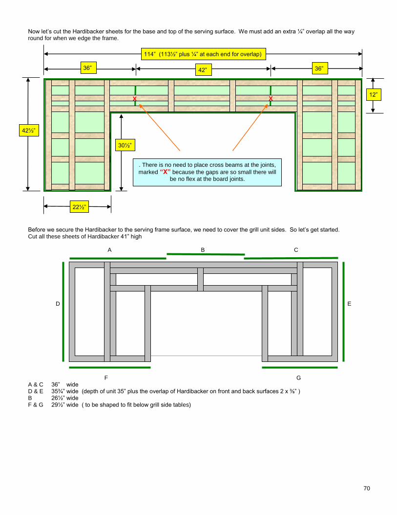
70
Now let’s cut the Hardibacker sheets for the base and top of the serving surface. We must add an extra ¼” overlap all the way round for when we edge the frame.
Before we secure the Hardibacker to the serving frame surface, we need to cover the grill unit sides. So let’s get started. Cut all these sheets of Hardibacker 41” high A B C D E F G A & C 36” wide D & E 35¾” wide (depth of unit 35” plus the overlap of Hardibacker on front and back surfaces 2 x ⅜” ) B 26½” wide F & G 29½” wide ( to be shaped to fit below grill side tables)
36” 36”
114” (113½” plus ¼” at each end for overlap)
42”
. There is no need to place cross beams at the joints,
marked “X” because the gaps are so small there will
be no flex at the board joints.
X X
42½”
12”
22½”
30½”
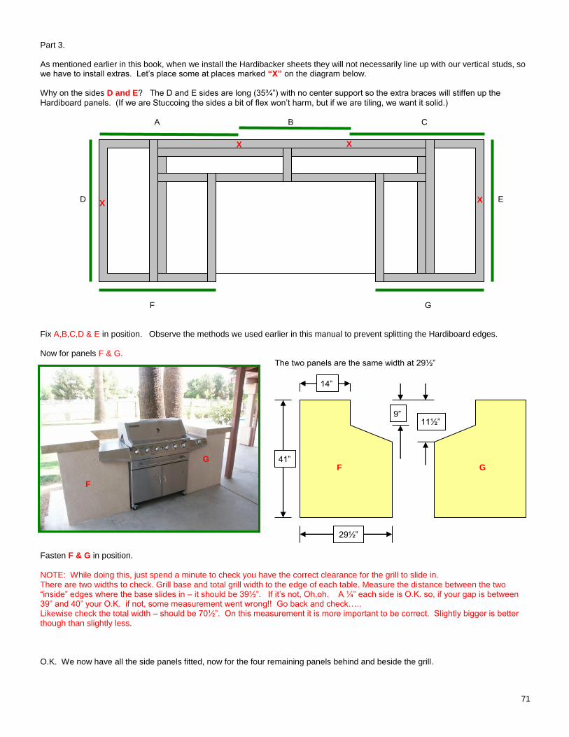
71
Part 3. As mentioned earlier in this book, when we install the Hardibacker sheets they will not necessarily line up with our vertical studs, so we have to install extras. Let’s place some at places marked “X” on the diagram below.
Why on the sides D and E? The D and E sides are long (35¾”) with no center support so the extra braces will stiffen up the
Hardiboard panels. (If we are Stuccoing the sides a bit of flex won’t harm, but if we are tiling, we want it solid.) A B C D E F G Fix A,B,C,D & E in position. Observe the methods we used earlier in this manual to prevent splitting the Hardiboard edges. Now for panels F & G.
The two panels are the same width at 29½”
Fasten F & G in position.
NOTE: While doing this, just spend a minute to check you have the correct clearance for the grill to slide in. There are two widths to check. Grill base and total grill width to the edge of each table. Measure the distance between the two “inside” edges where the base slides in – it should be 39½”. If it’s not, Oh,oh. A ¼” each side is O.K. so, if your gap is between 39” and 40” your O.K. if not, some measurement went wrong!! Go back and check….. Likewise check the total width – should be 70½”. On this measurement it is more important to be correct. Slightly bigger is better though than slightly less. O.K. We now have all the side panels fitted, now for the four remaining panels behind and beside the grill.
X X
X X
F
G
29½”
41”
9” 11½”
14”
F G
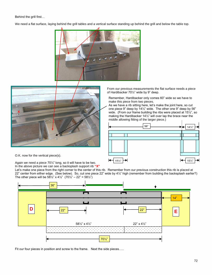
72
Behind the grill first… We need a flat surface, laying behind the grill tables and a vertical surface standing up behind the grill and below the table top.
From our previous measurements the flat surface needs a piece of Hardibacker 70½” wide by 9” deep.
Remember, Hardibacker only comes 60” wide so we have to make this piece from two pieces. As we have a rib sitting here, let’s make the joint here, so cut one piece 9” deep by 14½” wide. The other one 9” deep by 56” wide. (From our frame building the ribs were placed at 15½”, so making the Hardibacker 14½” will over lap the brace near the middle allowing fitting of the larger piece.)
O.K. now for the vertical piece(s). Again we need a piece 70½” long, so it will have to be two. In the above picture we can see a backsplash support rib “X”
Let’s make one piece from the right corner to the center of this rib. Remember from our previous construction this rib is placed at 22” center from either edge. (See below). So, cut one piece 22” wide by 4½” high (remember from building the backsplash earlier?) The other piece will be 58½” x 4½” (70½” – 22” = 58½”) 58½” x 4½” 22” x 4½” Fit our four pieces in position and screw to the frame. Next the side pieces…..
15½” 15½”
14½” 56”
X
14”
22” D E
36”
22”
70½”
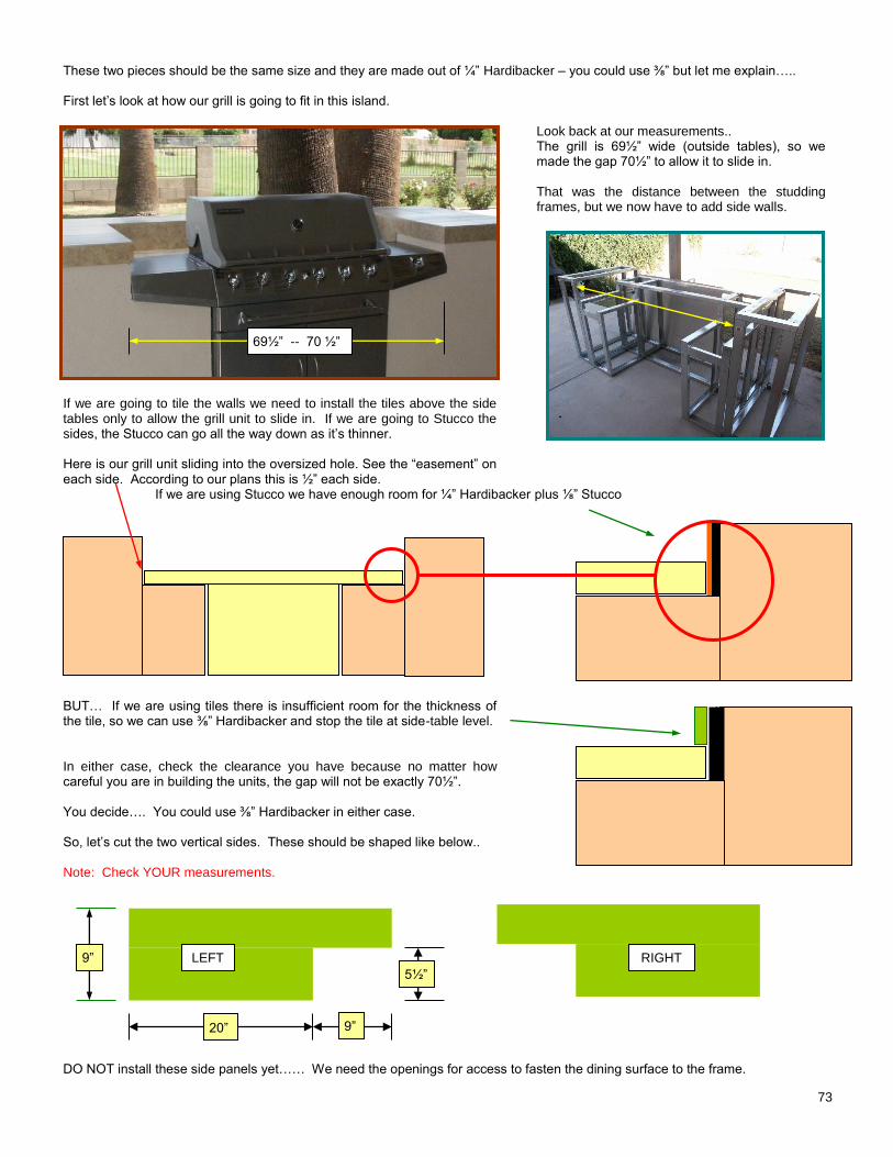
73
These two pieces should be the same size and they are made out of ¼” Hardibacker – you could use ⅜” but let me explain….. First let’s look at how our grill is going to fit in this island.
Look back at our measurements.. The grill is 69½” wide (outside tables), so we made the gap 70½” to allow it to slide in.
That was the distance between the studding frames, but we now have to add side walls.
If we are going to tile the walls we need to install the tiles above the side tables only to allow the grill unit to slide in. If we are going to Stucco the sides, the Stucco can go all the way down as it’s thinner. Here is our grill unit sliding into the oversized hole. See the “easement” on each side. According to our plans this is ½” each side.
If we are using Stucco we have enough room for ¼” Hardibacker plus ⅛” Stucco BUT… If we are using tiles there is insufficient room for the thickness of the tile, so we can use ⅜” Hardibacker and stop the tile at side-table level. In either case, check the clearance you have because no matter how careful you are in building the units, the gap will not be exactly 70½”. You decide…. You could use ⅜” Hardibacker in either case. So, let’s cut the two vertical sides. These should be shaped like below.. Note: Check YOUR measurements. DO NOT install these side panels yet…… We need the openings for access to fasten the dining surface to the frame.
69½” -- 70 ½”
LEFT RIGHT 9”
20”
5½”
9”
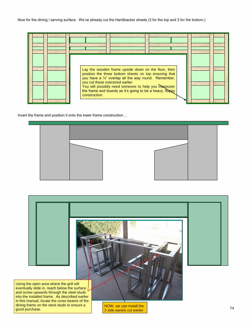
74
Now for the dining / serving surface. We’ve already cut the Hardibacker sheets (3 for the top and 3 for the bottom.)
Invert the frame and position it onto the lower frame construction…
Lay the wooden frame upside down on the floor, then position the three bottom sheets on top ensuring that you have a ¼” overlap all the way round. Remember, you cut these oversized earlier. You will possibly need someone to help you maneuver the frame and boards as it’s going to be a heavy, floppy construction.
Using the open area where the grill will eventually slide in, reach below the surface and screw upwards through the steel studs into the installed frame. As described earlier in this manual, locate the cross beams of the dining frame on the steel studs to ensure a good purchase.
NOW, we can install the 2 side panels cut earlier
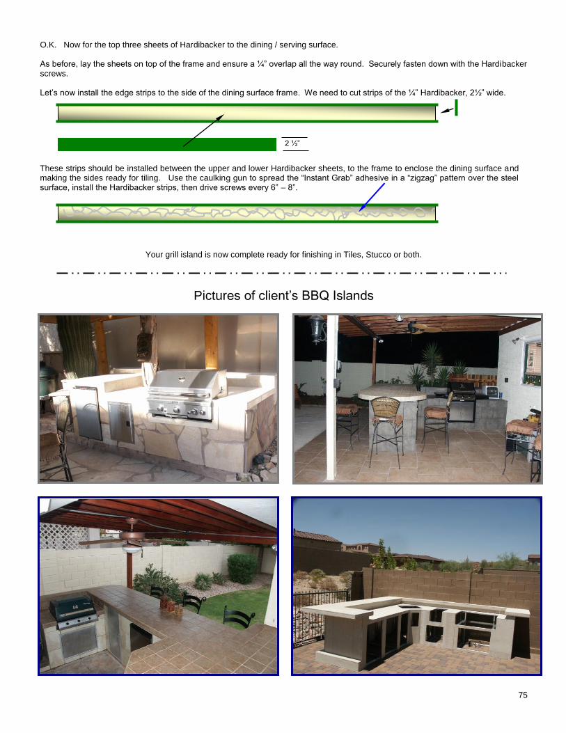
75
O.K. Now for the top three sheets of Hardibacker to the dining / serving surface. As before, lay the sheets on top of the frame and ensure a ¼” overlap all the way round. Securely fasten down with the Hardibacker screws. Let’s now install the edge strips to the side of the dining surface frame. We need to cut strips of the ¼” Hardibacker, 2½” wide.
These strips should be installed between the upper and lower Hardibacker sheets, to the frame to enclose the dining surface and making the sides ready for tiling. Use the caulking gun to spread the “Instant Grab” adhesive in a “zigzag” pattern over the steel surface, install the Hardibacker strips, then drive screws every 6” – 8”.
Your grill island is now complete ready for finishing in Tiles, Stucco or both.
Pictures of client’s BBQ Islands
2 ½”
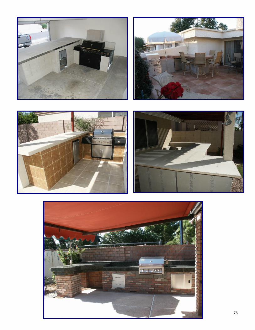
76
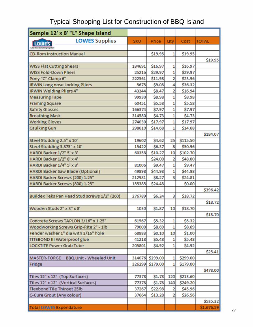
77
Typical Shopping List for Construction of BBQ Island
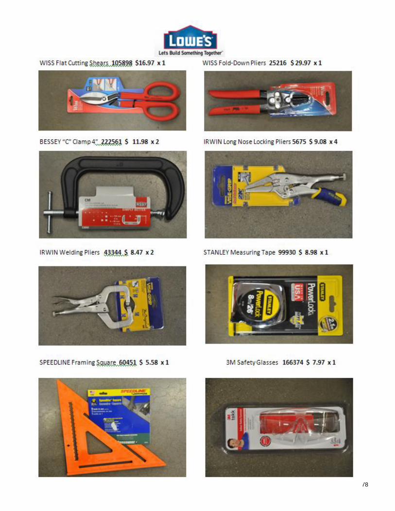
78
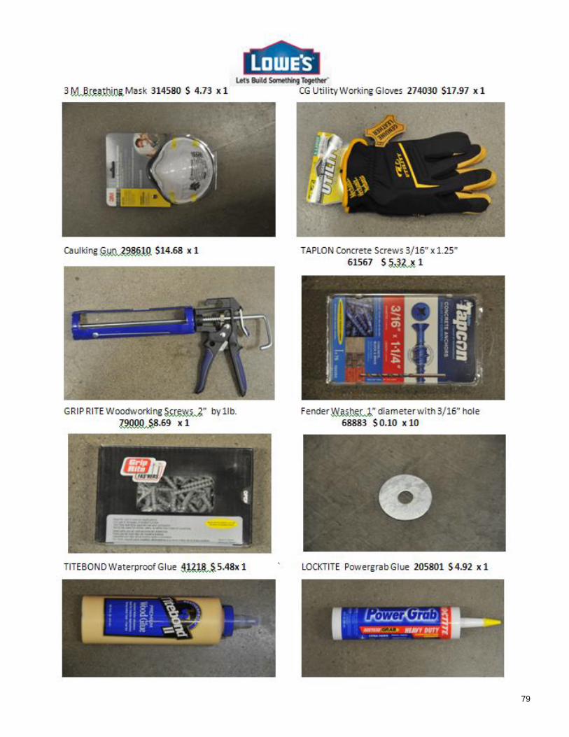
79
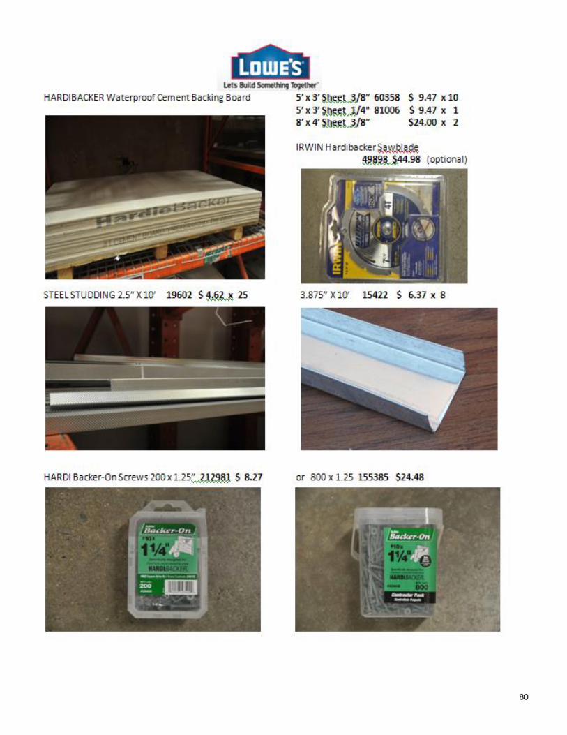
80
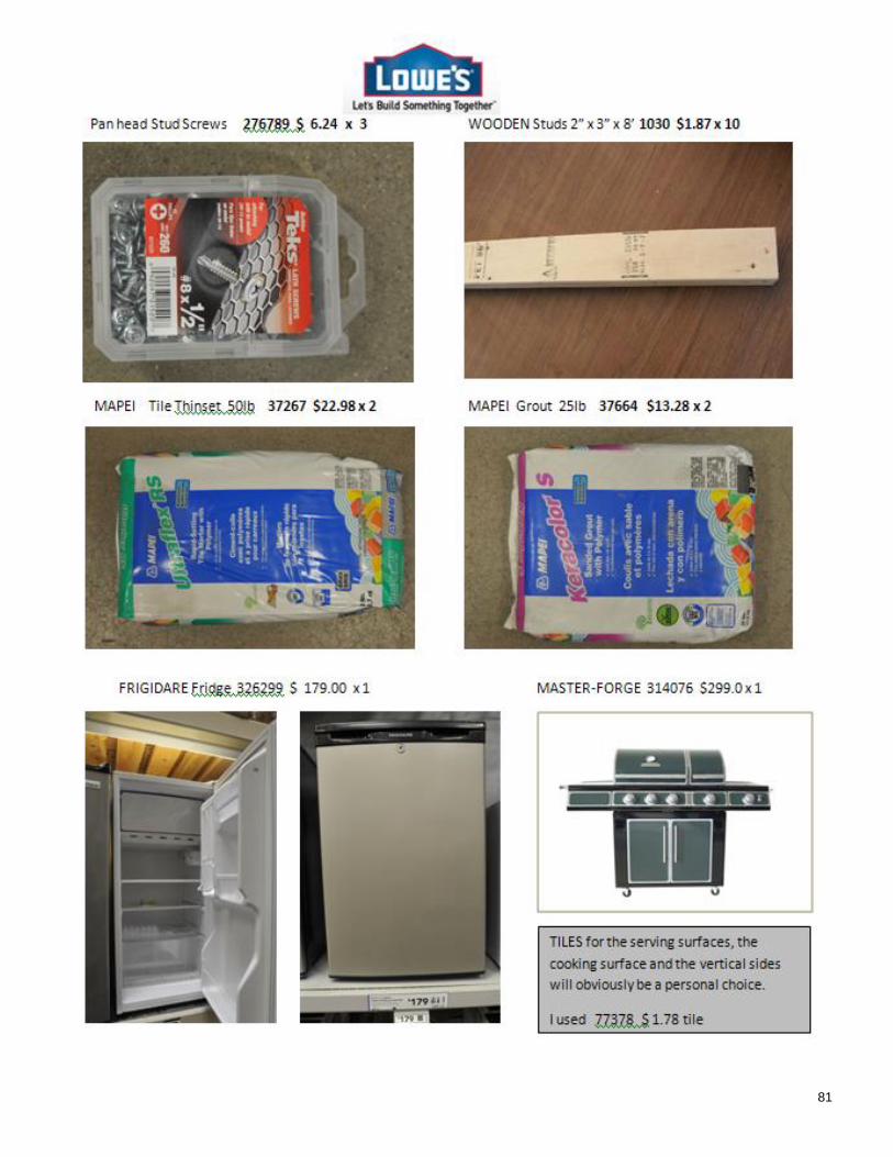
81