Embed Size (px)
Citation preview
Build Manual
Titan 1 (Ruby & Diamond Editions) Revision 1.2

Kudo3D Titan 1 - Build Manual Ver. 1.2
2 of 33
Copyright © 2014 by Kudo3D. This material may be distributed only subject to the terms and conditions set forth in the Creative Commons Attribution-NonCommercial-NoDerivatives 4.0 International License or later. The latest version is presently available at http://creativecommons.org/licenses/by-nc-nd/4.0/.
Kudo3D Titan 1 - Build Manual Ver. 1.2
3 of 33
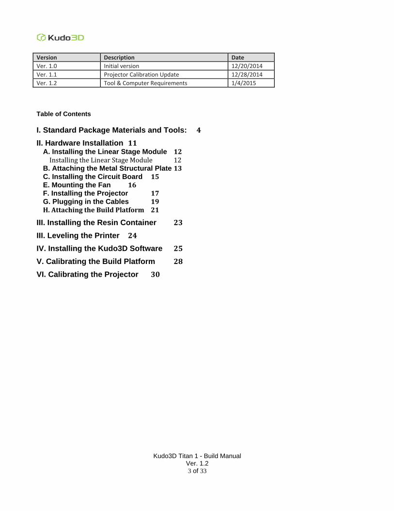
Version Description Date
Ver. 1.0 Initial version 12/20/2014
Ver. 1.1 Projector Calibration Update 12/28/2014
Ver. 1.2 Tool & Computer Requirements 1/4/2015
Table of Contents
I. Standard Package Materials and Tools: 4
II. Hardware Installation 11 A. Installing the Linear Stage Module 12
Installing the Linear Stage Module 12 B. Attaching the Metal Structural Plate 13 C. Installing the Circuit Board 15 E. Mounting the Fan 16 F. Installing the Projector 17 G. Plugging in the Cables 19 H. Attaching the Build Platform 21
III. Installing the Resin Container 23
III. Leveling the Printer 24
IV. Installing the Kudo3D Software 25
V. Calibrating the Build Platform 28
VI. Calibrating the Projector 30
Kudo3D Titan 1 - Build Manual Ver. 1.2
4 of 33
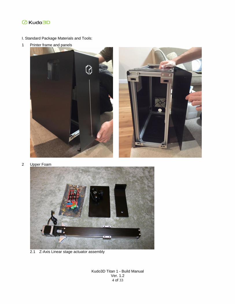
I. Standard Package Materials and Tools:
1 Printer frame and panels
2 Upper Foam
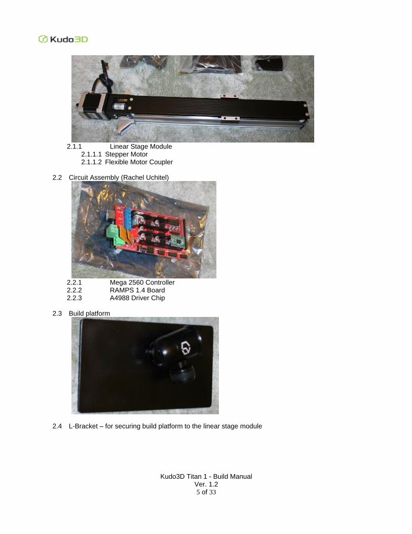
2.1 Z-Axis Linear stage actuator assembly
Kudo3D Titan 1 - Build Manual Ver. 1.2
5 of 33
2.1.1 Linear Stage Module
2.1.1.1 Stepper Motor 2.1.1.2 Flexible Motor Coupler
2.2 Circuit Assembly (Rachel Uchitel)
2.2.1 Mega 2560 Controller 2.2.2 RAMPS 1.4 Board 2.2.3 A4988 Driver Chip
2.3 Build platform
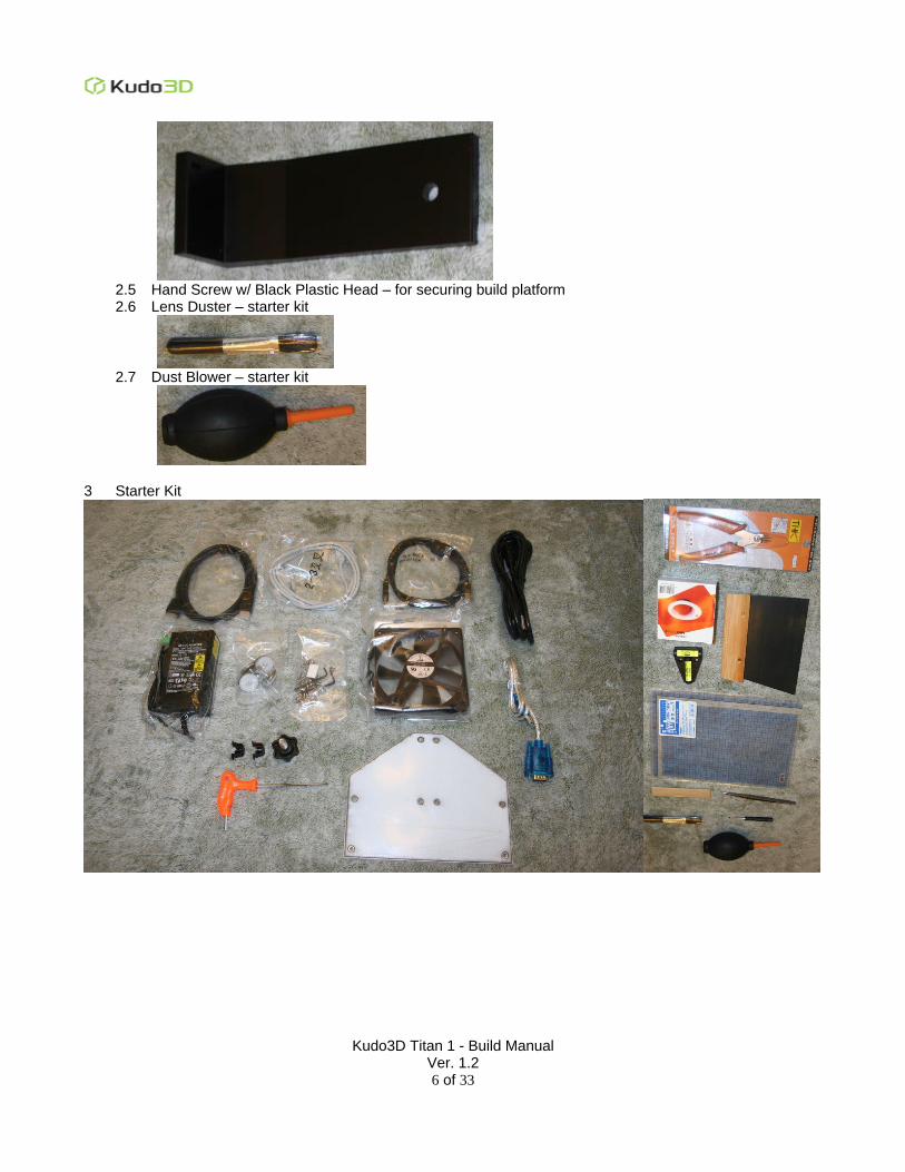
2.4 L-Bracket – for securing build platform to the linear stage module
Kudo3D Titan 1 - Build Manual Ver. 1.2
6 of 33
2.5 Hand Screw w/ Black Plastic Head – for securing build platform 2.6 Lens Duster – starter kit
2.7 Dust Blower – starter kit
3 Starter Kit
Kudo3D Titan 1 - Build Manual Ver. 1.2
7 of 33
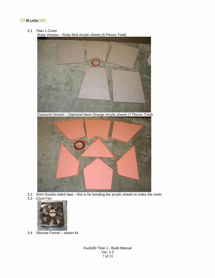
3.1 Titan 1 Cover Ruby Version – Ruby Red Acrylic sheets (5 Pieces Total)
Diamond Version – Diamond Neon Orange Acrylic sheets (7 Pieces Total)
3.2 3mm Double-sided tape – this is for bonding the acrylic sheets to make the cover 3.3 12cm Fan
3.4 Silicone Funnel – starter kit
Kudo3D Titan 1 - Build Manual Ver. 1.2
8 of 33
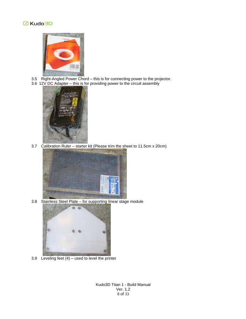
3.5 Right-Angled Power Chord – this is for connecting power to the projector. 3.6 12V DC Adapter – this is for providing power to the circuit assembly
3.7 Calibration Ruler – starter kit (Please trim the sheet to 11.5cm x 20cm)
3.8 Stainless Steel Plate – for supporting linear stage module
3.9 Leveling feet (4) – used to level the printer
Kudo3D Titan 1 - Build Manual Ver. 1.2
9 of 33
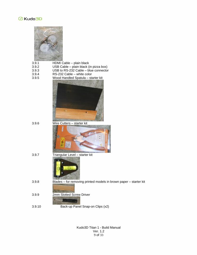
3.9.1 HDMI Cable – plain black 3.9.2 USB Cable – plain black (in pizza box) 3.9.3 USB to RS-232 Cable – blue connector 3.9.4 RS-232 Cable – white color 3.9.5 Wood Handled Spatula – starter kit
3.9.6 Wire Cutters – starter kit
3.9.7 Triangular Level – starter kit
3.9.8 Blades – for removing printed models in brown paper – starter kit
3.9.9 2mm Slotted Screw Driver
3.9.10 Back-up Panel Snap-on Clips (x2)
Kudo3D Titan 1 - Build Manual Ver. 1.2
10 of 33
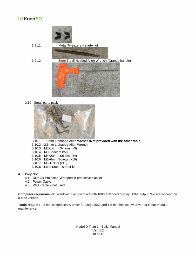
3.9.11 Metal Tweezers – starter kit
3.9.12 3mm T-ball Headed Allen Wrench (Orange handle)
3.10 Small parts pack
3.10.1 1.5mm L-shaped Allen Wrench (Not provided with the other tools) 3.10.2 2.5mm L-shaped Allen Wrench 3.10.3 M3x14mm Screws (x3) 3.10.4 M3 Spacers (x2) 3.10.5 M4x20mm Screws (x4) 3.10.6 M5x6mm Screws (x10) 3.10.7 M5 T-Nuts (x10) 3.10.8 Lens Stop – starter kit
4 Projector
4.1 DLP 3D Projector (Wrapped in protective plastic) 4.2 Power Cable 4.3 VGA Cable – not used
Computer requirements: Windows 7 or 8 with a 1920x1080 extended display HDMI output. We are working on a Mac version.
Tools required: 2 mm slotted screw driver for Mega2560 and 1.5 mm hex screw driver for linear module maintenance.
Kudo3D Titan 1 - Build Manual Ver. 1.2
11 of 33
II. Hardware Installation
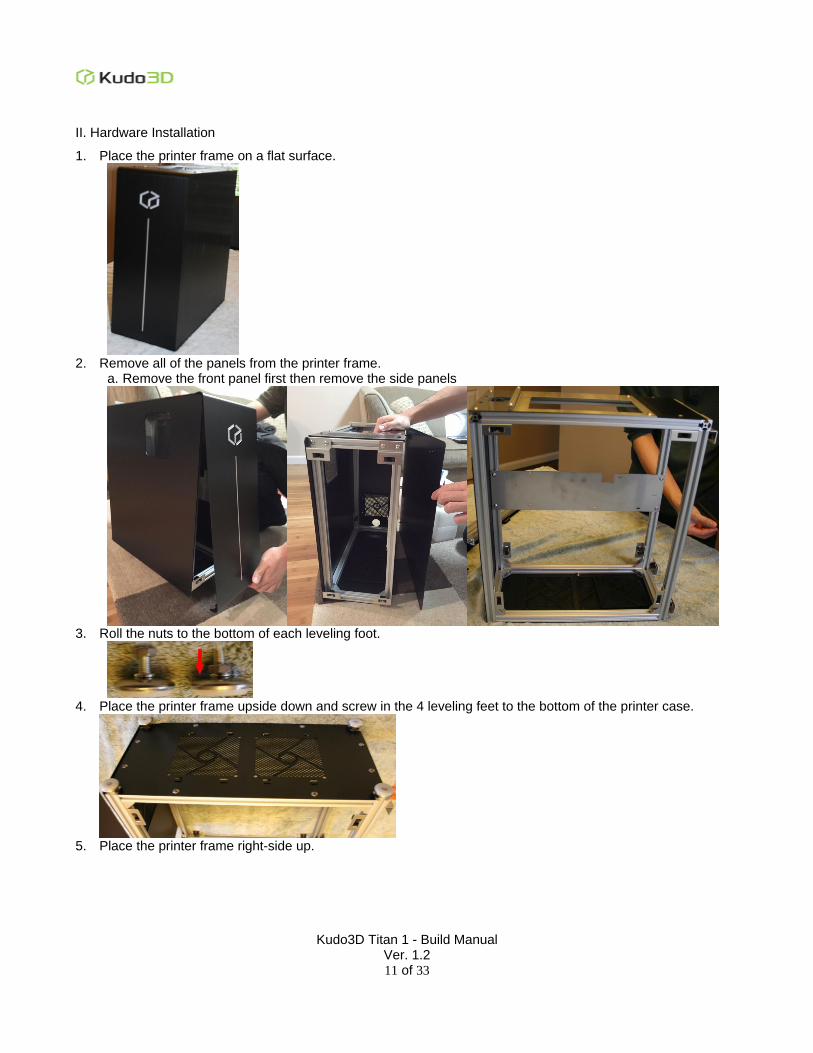
1. Place the printer frame on a flat surface.
2. Remove all of the panels from the printer frame.
a. Remove the front panel first then remove the side panels
3. Roll the nuts to the bottom of each leveling foot.
4. Place the printer frame upside down and screw in the 4 leveling feet to the bottom of the printer case.
5. Place the printer frame right-side up.
Kudo3D Titan 1 - Build Manual Ver. 1.2
12 of 33
A. Installing the Linear Stage Module
Installing the Linear Stage Module
1. Loosen the two T-nuts on the triangular corner brackets to the tip of the screws until the T-nuts are barely screwed on.
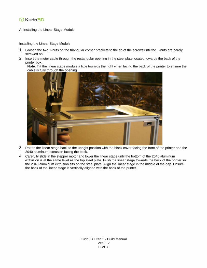
2. Insert the motor cable through the rectangular opening in the steel plate located towards the back of the printer box.
Note: Tilt the linear stage module a little towards the right when facing the back of the printer to ensure the cable is fully through the opening
3. Rotate the linear stage back to the upright position with the black cover facing the front of the printer and the
2040 aluminum extrusion facing the back.
4. Carefully slide in the stepper motor and lower the linear stage until the bottom of the 2040 aluminum extrusion is at the same level as the top steel plate. Push the linear stage towards the back of the printer so the 2040 aluminum extrusion sits on the steel plate. Align the linear stage in the middle of the gap. Ensure the back of the linear stage is vertically aligned with the back of the printer.
Kudo3D Titan 1 - Build Manual Ver. 1.2
13 of 33
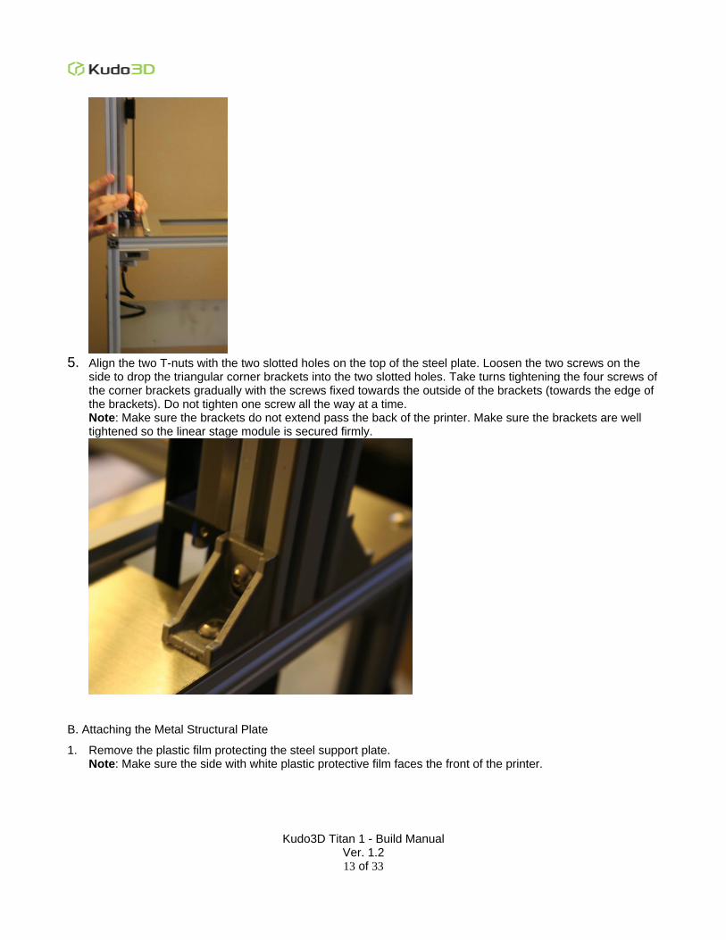
5. Align the two T-nuts with the two slotted holes on the top of the steel plate. Loosen the two screws on the
side to drop the triangular corner brackets into the two slotted holes. Take turns tightening the four screws of the corner brackets gradually with the screws fixed towards the outside of the brackets (towards the edge of the brackets). Do not tighten one screw all the way at a time. Note: Make sure the brackets do not extend pass the back of the printer. Make sure the brackets are well tightened so the linear stage module is secured firmly.
B. Attaching the Metal Structural Plate
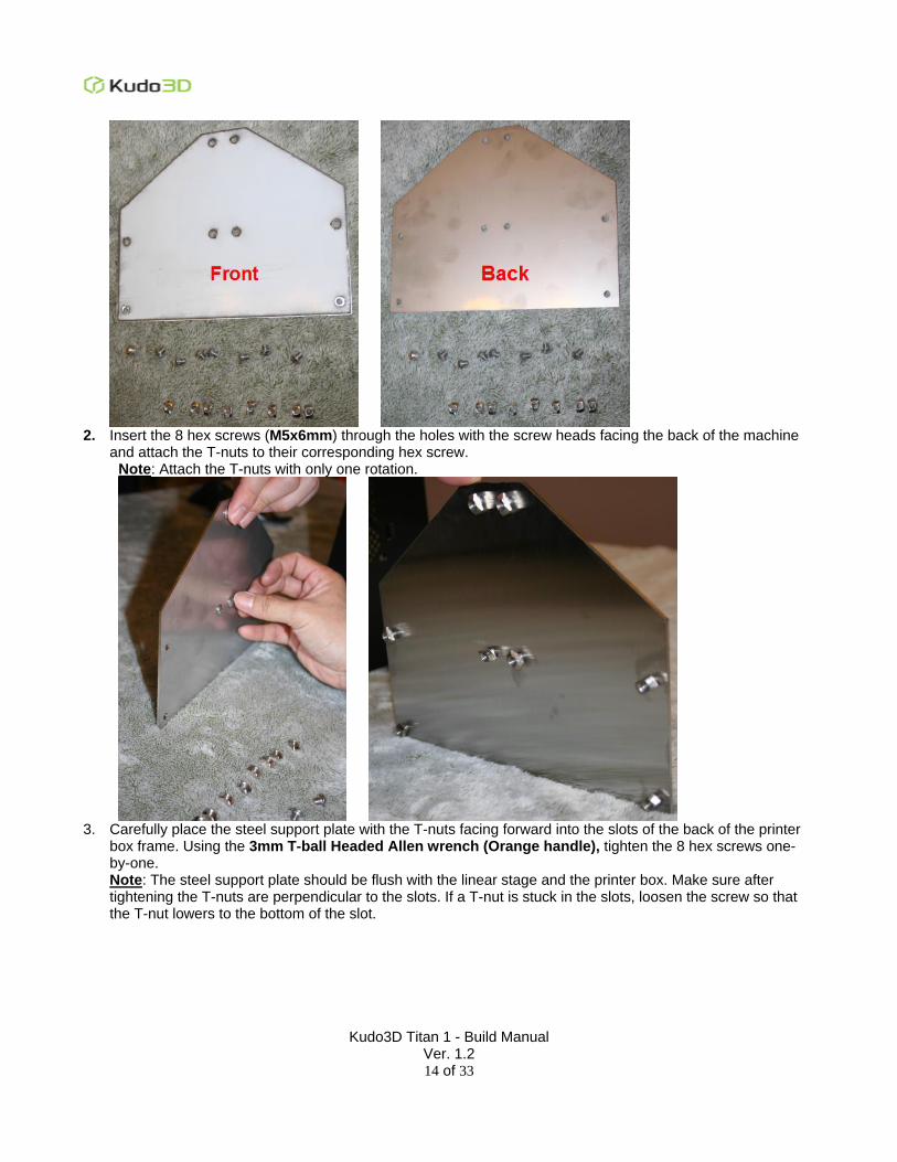
1. Remove the plastic film protecting the steel support plate. Note: Make sure the side with white plastic protective film faces the front of the printer.
Kudo3D Titan 1 - Build Manual Ver. 1.2
14 of 33
2. Insert the 8 hex screws (M5x6mm) through the holes with the screw heads facing the back of the machine
and attach the T-nuts to their corresponding hex screw. Note: Attach the T-nuts with only one rotation.
3. Carefully place the steel support plate with the T-nuts facing forward into the slots of the back of the printer
box frame. Using the 3mm T-ball Headed Allen wrench (Orange handle), tighten the 8 hex screws one-by-one. Note: The steel support plate should be flush with the linear stage and the printer box. Make sure after tightening the T-nuts are perpendicular to the slots. If a T-nut is stuck in the slots, loosen the screw so that the T-nut lowers to the bottom of the slot.
Kudo3D Titan 1 - Build Manual Ver. 1.2
15 of 33
C. Installing the Circuit Board
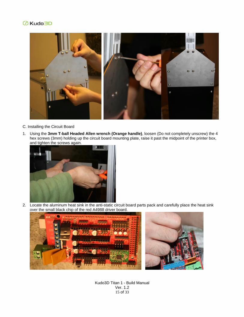
1. Using the 3mm T-ball Headed Allen wrench (Orange handle), loosen (Do not completely unscrew) the 4 hex screws (3mm) holding up the circuit board mounting plate, raise it past the midpoint of the printer box, and tighten the screws again.
2. Locate the aluminum heat sink in the anti-static circuit board parts pack and carefully place the heat sink
over the small black chip of the red A4988 driver board.
Kudo3D Titan 1 - Build Manual Ver. 1.2
16 of 33
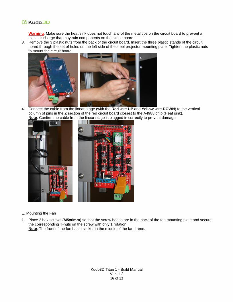
Warning: Make sure the heat sink does not touch any of the metal tips on the circuit board to prevent a static discharge that may ruin components on the circuit board.
3. Remove the 3 plastic nuts from the back of the circuit board. Insert the three plastic stands of the circuit board through the set of holes on the left side of the steel projector mounting plate. Tighten the plastic nuts to mount the circuit board.
4. Connect the cable from the linear stage (with the Red wire UP and Yellow wire DOWN) to the vertical
column of pins in the Z section of the red circuit board closest to the A4988 chip (Heat sink). Note: Confirm the cable from the linear stage is plugged in correctly to prevent damage.
E. Mounting the Fan
1. Place 2 hex screws (M5x6mm) so that the screw heads are in the back of the fan mounting plate and secure the corresponding T-nuts on the screw with only 1 rotation. Note: The front of the fan has a sticker in the middle of the fan frame.
Kudo3D Titan 1 - Build Manual Ver. 1.2
17 of 33
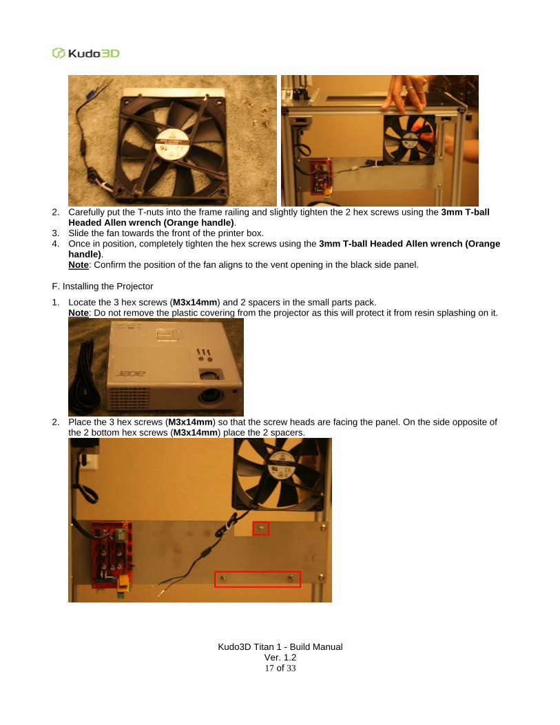
2. Carefully put the T-nuts into the frame railing and slightly tighten the 2 hex screws using the 3mm T-ball
Headed Allen wrench (Orange handle). 3. Slide the fan towards the front of the printer box. 4. Once in position, completely tighten the hex screws using the 3mm T-ball Headed Allen wrench (Orange
handle). Note: Confirm the position of the fan aligns to the vent opening in the black side panel.
F. Installing the Projector
1. Locate the 3 hex screws (M3x14mm) and 2 spacers in the small parts pack. Note: Do not remove the plastic covering from the projector as this will protect it from resin splashing on it.
2. Place the 3 hex screws (M3x14mm) so that the screw heads are facing the panel. On the side opposite of
the 2 bottom hex screws (M3x14mm) place the 2 spacers.
Kudo3D Titan 1 - Build Manual Ver. 1.2
18 of 33
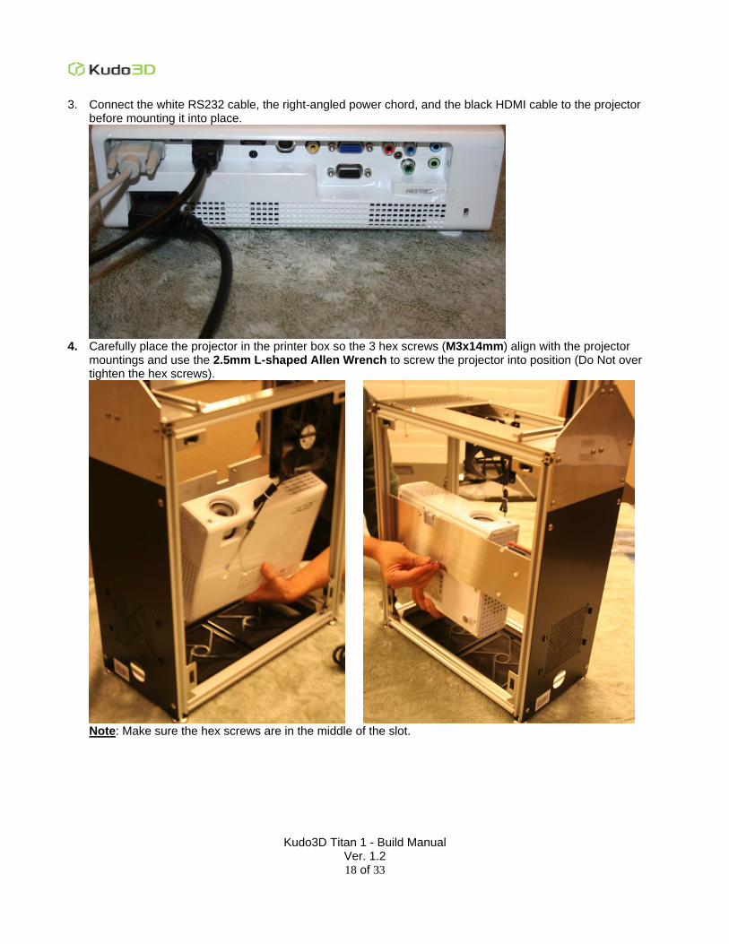
3. Connect the white RS232 cable, the right-angled power chord, and the black HDMI cable to the projector before mounting it into place.
4. Carefully place the projector in the printer box so the 3 hex screws (M3x14mm) align with the projector
mountings and use the 2.5mm L-shaped Allen Wrench to screw the projector into position (Do Not over tighten the hex screws).
Note: Make sure the hex screws are in the middle of the slot.
Kudo3D Titan 1 - Build Manual Ver. 1.2
19 of 33
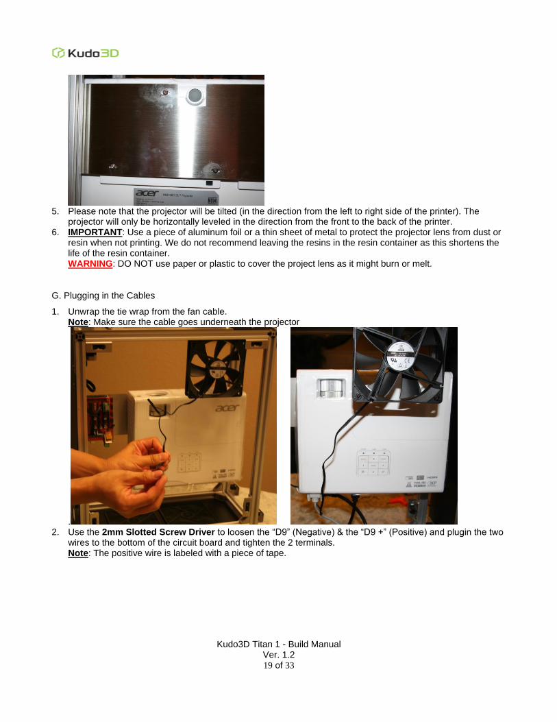
5. Please note that the projector will be tilted (in the direction from the left to right side of the printer). The
projector will only be horizontally leveled in the direction from the front to the back of the printer. 6. IMPORTANT: Use a piece of aluminum foil or a thin sheet of metal to protect the projector lens from dust or
resin when not printing. We do not recommend leaving the resins in the resin container as this shortens the life of the resin container. WARNING: DO NOT use paper or plastic to cover the project lens as it might burn or melt.
G. Plugging in the Cables
1. Unwrap the tie wrap from the fan cable. Note: Make sure the cable goes underneath the projector
. 2. Use the 2mm Slotted Screw Driver to loosen the “D9” (Negative) & the “D9 +” (Positive) and plugin the two
wires to the bottom of the circuit board and tighten the 2 terminals. Note: The positive wire is labeled with a piece of tape.
Kudo3D Titan 1 - Build Manual Ver. 1.2
20 of 33
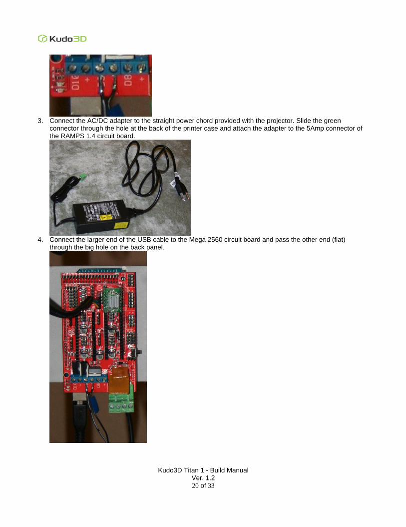
3. Connect the AC/DC adapter to the straight power chord provided with the projector. Slide the green
connector through the hole at the back of the printer case and attach the adapter to the 5Amp connector of the RAMPS 1.4 circuit board.
4. Connect the larger end of the USB cable to the Mega 2560 circuit board and pass the other end (flat)
through the big hole on the back panel.
Kudo3D Titan 1 - Build Manual Ver. 1.2
21 of 33
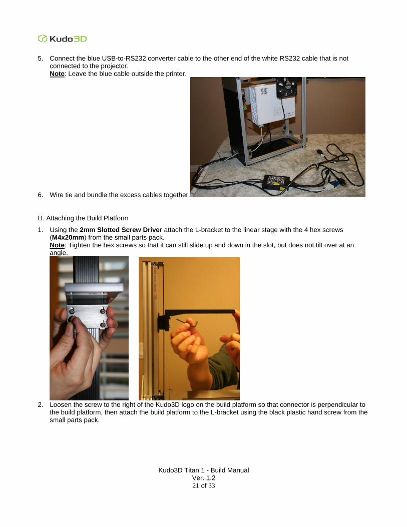
5. Connect the blue USB-to-RS232 converter cable to the other end of the white RS232 cable that is not connected to the projector. Note: Leave the blue cable outside the printer.
6. Wire tie and bundle the excess cables together.
H. Attaching the Build Platform
1. Using the 2mm Slotted Screw Driver attach the L-bracket to the linear stage with the 4 hex screws (M4x20mm) from the small parts pack. Note: Tighten the hex screws so that it can still slide up and down in the slot, but does not tilt over at an angle.
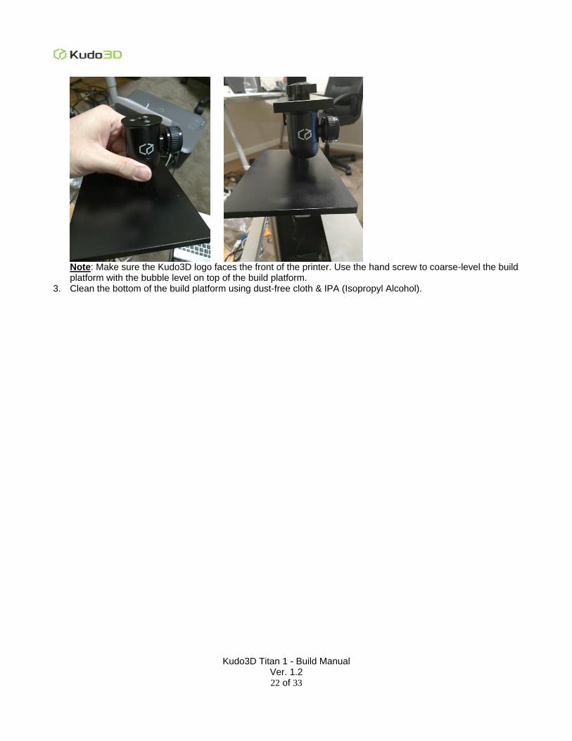
2. Loosen the screw to the right of the Kudo3D logo on the build platform so that connector is perpendicular to
the build platform, then attach the build platform to the L-bracket using the black plastic hand screw from the small parts pack.
Kudo3D Titan 1 - Build Manual Ver. 1.2
22 of 33
Note: Make sure the Kudo3D logo faces the front of the printer. Use the hand screw to coarse-level the build platform with the bubble level on top of the build platform.
3. Clean the bottom of the build platform using dust-free cloth & IPA (Isopropyl Alcohol).
Kudo3D Titan 1 - Build Manual Ver. 1.2
23 of 33
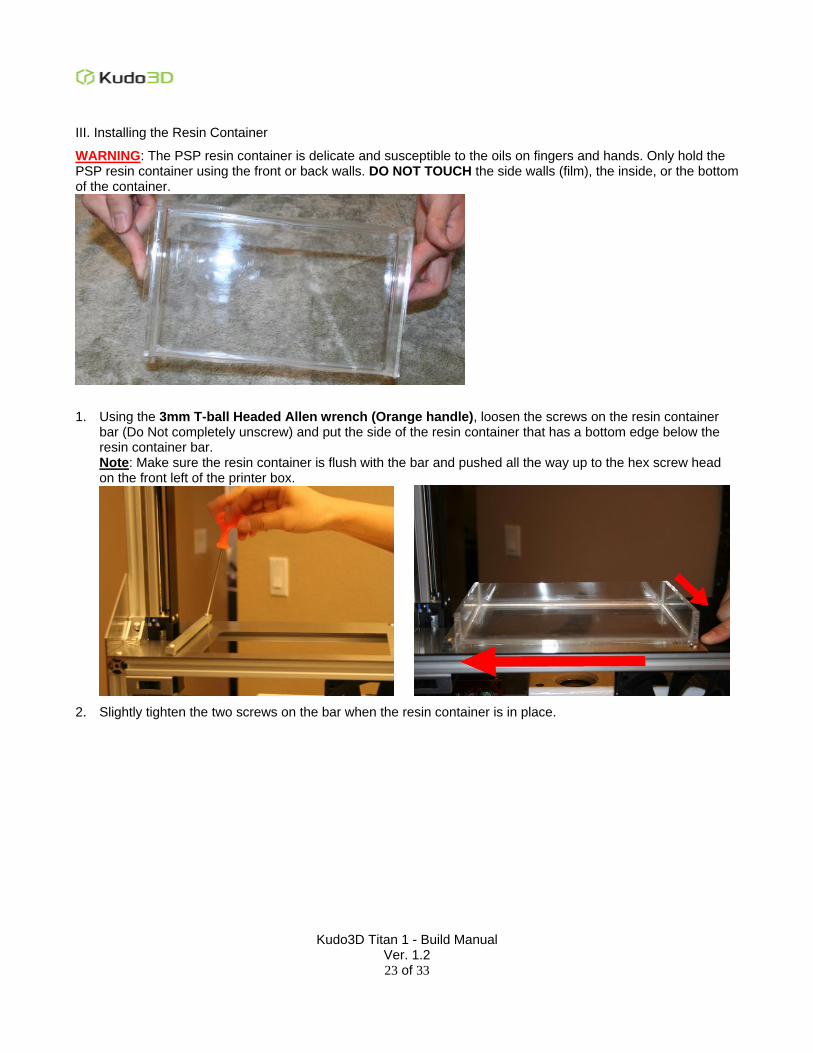
III. Installing the Resin Container
WARNING: The PSP resin container is delicate and susceptible to the oils on fingers and hands. Only hold the PSP resin container using the front or back walls. DO NOT TOUCH the side walls (film), the inside, or the bottom of the container.
1. Using the 3mm T-ball Headed Allen wrench (Orange handle), loosen the screws on the resin container bar (Do Not completely unscrew) and put the side of the resin container that has a bottom edge below the resin container bar. Note: Make sure the resin container is flush with the bar and pushed all the way up to the hex screw head on the front left of the printer box.
2. Slightly tighten the two screws on the bar when the resin container is in place.
Kudo3D Titan 1 - Build Manual Ver. 1.2
24 of 33
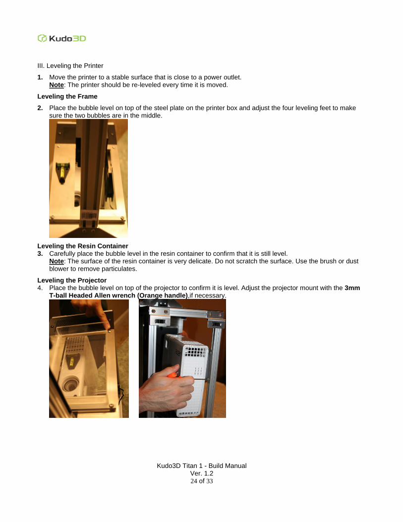
III. Leveling the Printer
1. Move the printer to a stable surface that is close to a power outlet. Note: The printer should be re-leveled every time it is moved.
Leveling the Frame
2. Place the bubble level on top of the steel plate on the printer box and adjust the four leveling feet to make sure the two bubbles are in the middle.
Leveling the Resin Container 3. Carefully place the bubble level in the resin container to confirm that it is still level.
Note: The surface of the resin container is very delicate. Do not scratch the surface. Use the brush or dust blower to remove particulates.
Leveling the Projector 4. Place the bubble level on top of the projector to confirm it is level. Adjust the projector mount with the 3mm
T-ball Headed Allen wrench (Orange handle),if necessary.
Kudo3D Titan 1 - Build Manual Ver. 1.2
25 of 33
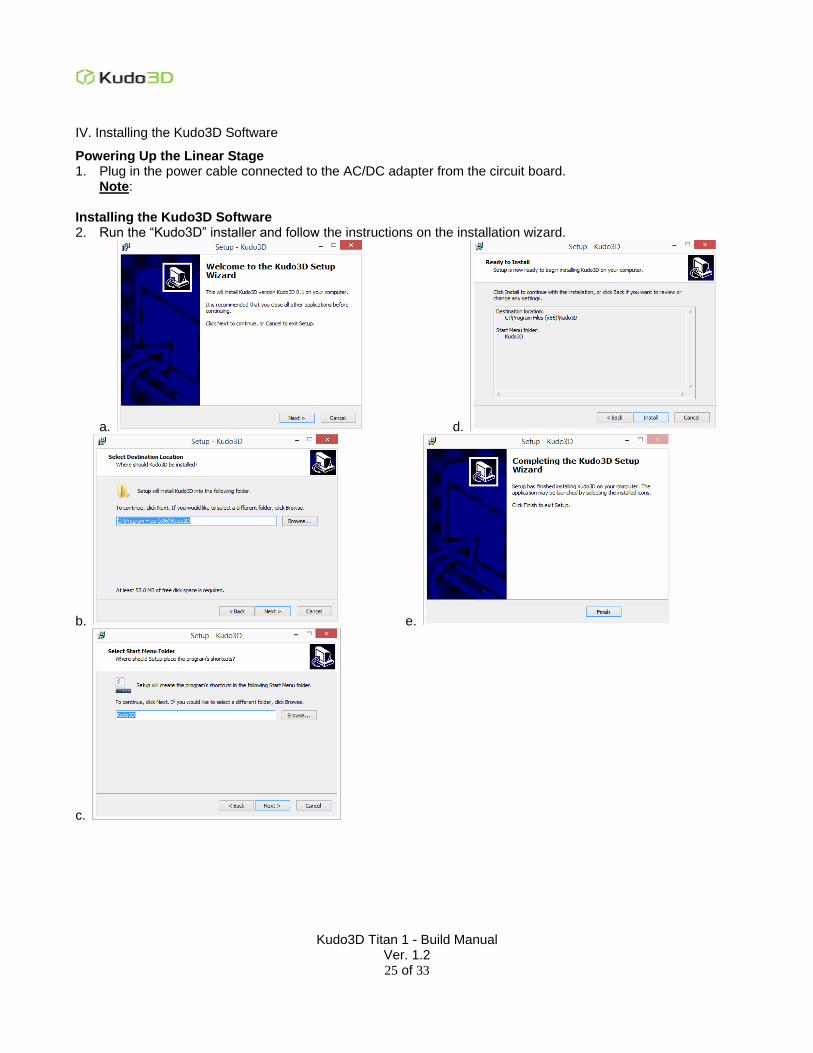
IV. Installing the Kudo3D Software
Powering Up the Linear Stage 1. Plug in the power cable connected to the AC/DC adapter from the circuit board.
Note: Installing the Kudo3D Software 2. Run the “Kudo3D” installer and follow the instructions on the installation wizard.
a. d.
b. e.
c.
Kudo3D Titan 1 - Build Manual Ver. 1.2
26 of 33
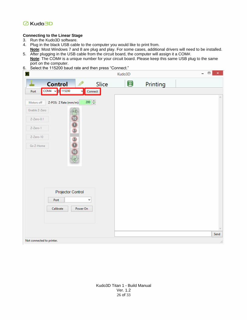
Connecting to the Linear Stage 3. Run the Kudo3D software. 4. Plug in the black USB cable to the computer you would like to print from.
Note: Most Windows 7 and 8 are plug and play. For some cases, additional drivers will need to be installed. 5. After plugging in the USB cable from the circuit board, the computer will assign it a COM#.
Note: The COM# is a unique number for your circuit board. Please keep this same USB plug to the same port on the computer.
6. Select the 115200 baud rate and then press “Connect.”

Kudo3D Titan 1 - Build Manual Ver. 1.2
27 of 33
7. Confirm the Kudo3D software is connected to the linear stage by pushing the +Z (10, 1, 0.1) and -Z (0.1, 1, 10) buttons, which will cause the build platform to move. Note: The number 0.1, 1, 10 represent the number of rotations the linear stage will move the build platform.
Kudo3D Titan 1 - Build Manual Ver. 1.2
28 of 33
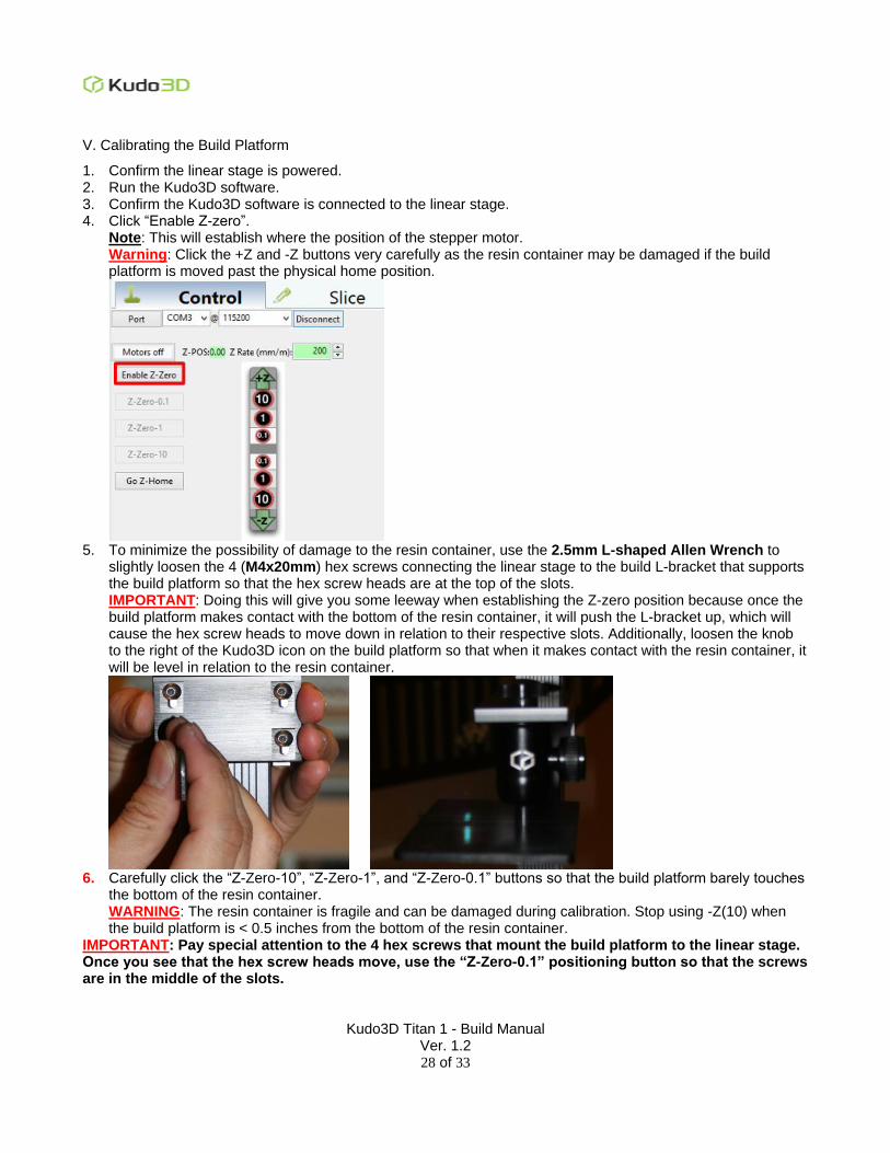
V. Calibrating the Build Platform
1. Confirm the linear stage is powered. 2. Run the Kudo3D software. 3. Confirm the Kudo3D software is connected to the linear stage. 4. Click “Enable Z-zero”.
Note: This will establish where the position of the stepper motor. Warning: Click the +Z and -Z buttons very carefully as the resin container may be damaged if the build platform is moved past the physical home position.
5. To minimize the possibility of damage to the resin container, use the 2.5mm L-shaped Allen Wrench to
slightly loosen the 4 (M4x20mm) hex screws connecting the linear stage to the build L-bracket that supports the build platform so that the hex screw heads are at the top of the slots. IMPORTANT: Doing this will give you some leeway when establishing the Z-zero position because once the build platform makes contact with the bottom of the resin container, it will push the L-bracket up, which will cause the hex screw heads to move down in relation to their respective slots. Additionally, loosen the knob to the right of the Kudo3D icon on the build platform so that when it makes contact with the resin container, it will be level in relation to the resin container.
6. Carefully click the “Z-Zero-10”, “Z-Zero-1”, and “Z-Zero-0.1” buttons so that the build platform barely touches
the bottom of the resin container. WARNING: The resin container is fragile and can be damaged during calibration. Stop using -Z(10) when the build platform is < 0.5 inches from the bottom of the resin container.
IMPORTANT: Pay special attention to the 4 hex screws that mount the build platform to the linear stage. Once you see that the hex screw heads move, use the “Z-Zero-0.1” positioning button so that the screws are in the middle of the slots.
Kudo3D Titan 1 - Build Manual Ver. 1.2
29 of 33
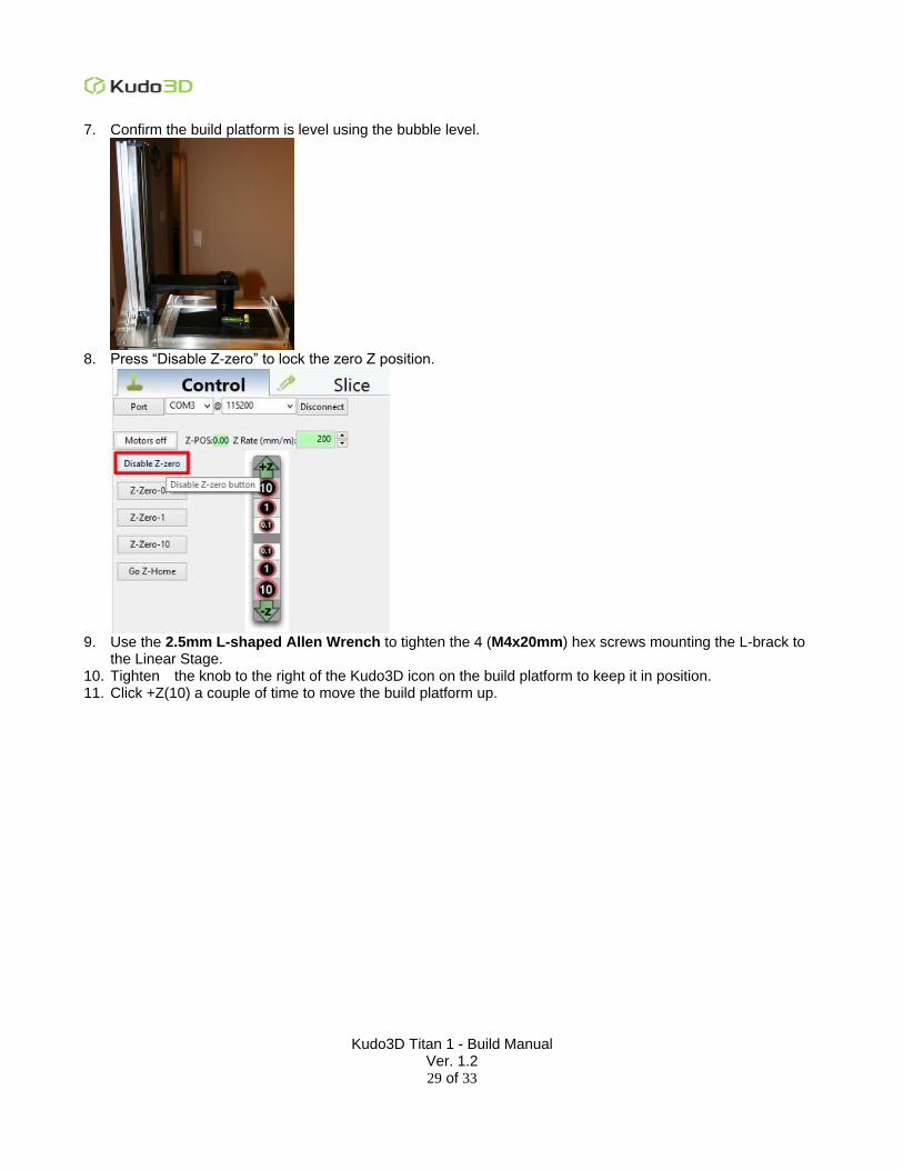
7. Confirm the build platform is level using the bubble level.
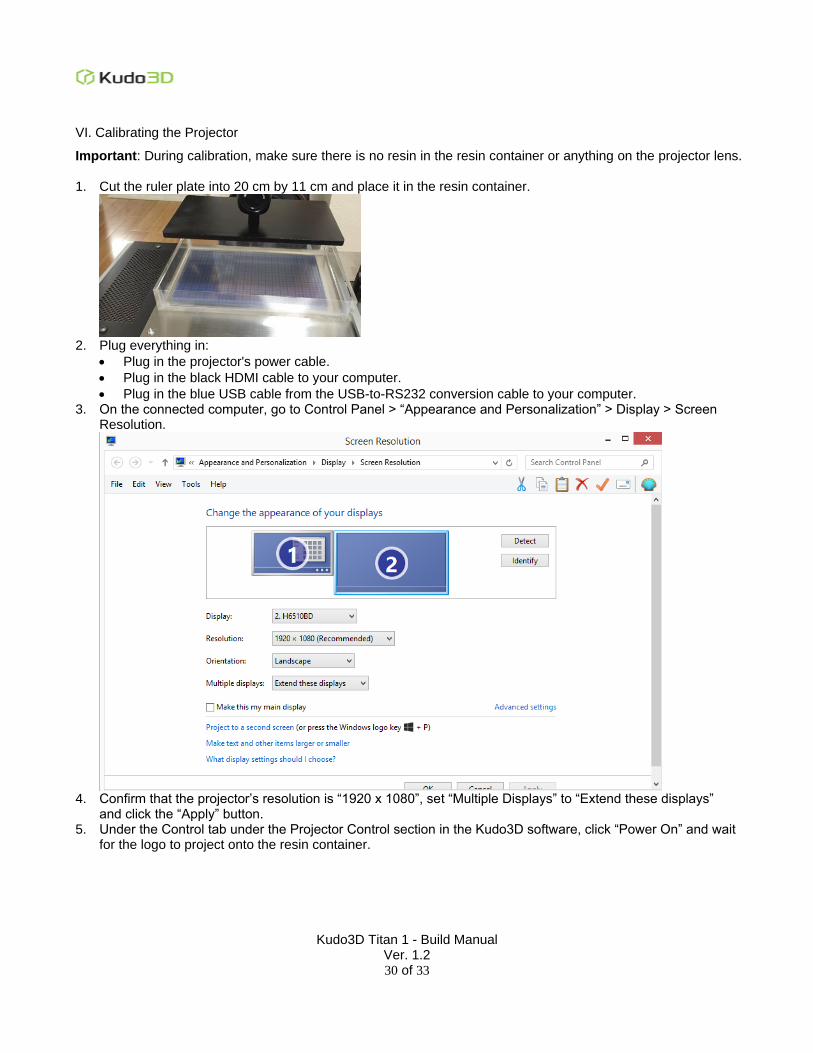
8. Press “Disable Z-zero” to lock the zero Z position.
9. Use the 2.5mm L-shaped Allen Wrench to tighten the 4 (M4x20mm) hex screws mounting the L-brack to
the Linear Stage. 10. Tighten the knob to the right of the Kudo3D icon on the build platform to keep it in position. 11. Click +Z(10) a couple of time to move the build platform up.
Kudo3D Titan 1 - Build Manual Ver. 1.2
30 of 33
VI. Calibrating the Projector
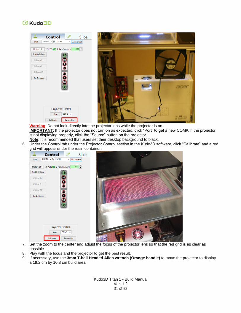
Important: During calibration, make sure there is no resin in the resin container or anything on the projector lens. 1. Cut the ruler plate into 20 cm by 11 cm and place it in the resin container.
2. Plug everything in:
Plug in the projector's power cable.
Plug in the black HDMI cable to your computer.
Plug in the blue USB cable from the USB-to-RS232 conversion cable to your computer. 3. On the connected computer, go to Control Panel > “Appearance and Personalization” > Display > Screen
Resolution.
4. Confirm that the projector’s resolution is “1920 x 1080”, set “Multiple Displays” to “Extend these displays”
and click the “Apply” button. 5. Under the Control tab under the Projector Control section in the Kudo3D software, click “Power On” and wait
for the logo to project onto the resin container.
Kudo3D Titan 1 - Build Manual Ver. 1.2
31 of 33
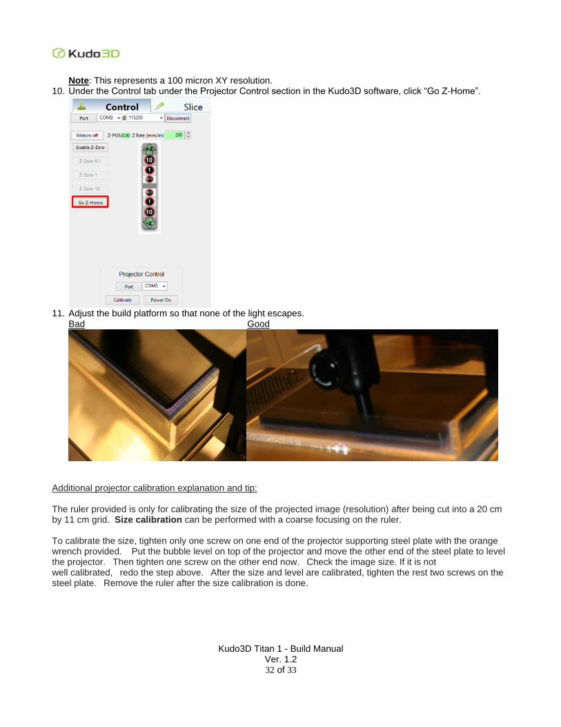
Warning: Do not look directly into the projector lens while the projector is on. IMPORTANT: If the projector does not turn on as expected, click “Port” to get a new COM#. If the projector is not displaying properly, click the “Source” button on the projector. Note: It is recommended that users set their desktop background to black.
6. Under the Control tab under the Projector Control section in the Kudo3D software, click “Calibrate” and a red grid will appear under the resin container.
7. Set the zoom to the center and adjust the focus of the projector lens so that the red grid is as clear as
possible. 8. Play with the focus and the projector to get the best result. 9. If necessary, use the 3mm T-ball Headed Allen wrench (Orange handle) to move the projector to display
a 19.2 cm by 10.8 cm build area.
Kudo3D Titan 1 - Build Manual Ver. 1.2
32 of 33
Note: This represents a 100 micron XY resolution. 10. Under the Control tab under the Projector Control section in the Kudo3D software, click “Go Z-Home”.
11. Adjust the build platform so that none of the light escapes.
Bad Good
Additional projector calibration explanation and tip: The ruler provided is only for calibrating the size of the projected image (resolution) after being cut into a 20 cm by 11 cm grid. Size calibration can be performed with a coarse focusing on the ruler. To calibrate the size, tighten only one screw on one end of the projector supporting steel plate with the orange wrench provided. Put the bubble level on top of the projector and move the other end of the steel plate to level the projector. Then tighten one screw on the other end now. Check the image size. If it is not well calibrated, redo the step above. After the size and level are calibrated, tighten the rest two screws on the steel plate. Remove the ruler after the size calibration is done.

Kudo3D Titan 1 - Build Manual Ver. 1.2
33 of 33
Now proceed to fine focus calibration. Please focus on the Teflon film surface on the resin container directly where the patterns are cured. Please use the "Calibrate" button in the software to generate the red grid image. Please look at the Teflon surface at an angle without staring directly at the projector lens. Adjust the focus of the grid lines as clear and uniform as possible in the central region. You will not get a nice focus for the four corners because of the spherical aberration of the lens module. After reaching a nice focus, please insert the lens stop provided. Make sure the focus maintains after the lens stop is inserted. If the lens does not extend all the way close to the top, you may not need the lens stop. To be safe, we recommend locking the lens with the stop to prevent defocusing during printing.